

Page 1
Manual
Installation
& Operation
/Chino
AB
REV. 0904
UPRIGHT MEAT DISPLAY CASE
AB
UPRIGHT MEAT DISPLAY CASE
P/N IGUP-AB-0904
INSTALLATION & OPERATION GUIDE
Page 2
Ta b l e of Contents
IGUP-AB-0904
General Instructions
THIS BOOKLET CONTAINS INFORMATION ON:
General Instructions ................................................. 2
Important Information ............................................. 3
Cut & Plan Views ....................................................... 4
NSF Installation Requirement ................................. 5
Installation ................................................................. 6
Plumbing .................................................................... 6
WASTE OUTLET AND P-TRAP .............................................................................. 6
Fractal Humidity System ......................................... 7
CONTROLLER SETTINGS ........................................................................................ 9
MODELS “SCH & SCHMS” - EMITTER NOZZLE CLEANING INSTRUCTiONS ........... 10
TROUBLE SHOOTING GUIDE ................................................................................ 11
MAJOR SYSTEM COMPONENTS .............................................................................. 11
Refrigeration ............................................................. 12
T-STAT LOCATION.................................................................................................. 12
Electrical .................................................................... 13
WIRING COLOR CODE ......................................................................................... 13
ASHRAE COLOR CODE .......................................................................................... 13
User Information ...................................................... 14
NON-GLARE GLASS ............................................................................................... 14
Maintenance .............................................................. 16
ELECTRICAL PRECAUTIONS ................................................................................... 16
REPLACING FLUORESCENT LAMPS ....................................................................... 16
Electrical and Refrigeration Specifications ............ 16
TIPS & TROUBLESHOOTING ................................................................................. 16
Electrical Schematics ............................................... 17
Appendices ................................................................ 22
Appendix A. – Temperature Guidelines Refrigerated ........................................ 22
Appendix B. – Application Recommendations Refrigerated .............................. 22
Appendix C. – Field Recommendations - Refrigerated ................................... 22
Appendix D. – Recommendations To User - Refrigerated ................................ 23
AB Upright Refrigerated Meat Display Case
SHIPPING DAMAGE
All equipment should be thoroughly examined for shipping damage before and during unloading.
This equipment has been carefully inspected at our factory and the carrier has assumed responsibility for safe
arrival. If damaged, either apparent or concealed, claim must
be made to the carrier.
APPARENT LOSS OR DAMAGE
If there is an obvious loss or damage, it must be noted on
the freight bill or express receipt and signed by the carrier’s
agent; otherwise, carrier may refuse claim. The carrier will
supply necessary claim forms.
CONCEALED LOSS OR DAMAGE
When loss or damage is not apparent until after equipment
is uncrated, a claim for concealed damage is made. Make
request in writing to carrier for inspection within 15 days,
and retain all packaging. The carrier will supply inspection
report and required claim forms.
SHORTAGES
Check your shipment for any possible shortages of material. If a shortage should exist and is found to be the responsibility of Hussmann Chino, notify Hussmann Chino. If
such a shortage involves the carrier, notify the carrier imme-
diately, and request an inspection. Hussmann Chino will
acknowledge shortages within ten days from receipt of
equipment.
HUSSMANN CHINO PRODUCT CONTROL
The serial number and shipping date of all equipment has
been recorded in Hussmann’s files for warranty and replacement part purposes. All correspondence pertaining
to warranty or parts ordering must include the serial number of each piece of equipment involved, in order to provide the customer with the correct parts.
Keep this booklet with the case at all times for future reference.
/Chino
A publication of
Hussmann® Chino
13770 Ramona Avenue • Chino, California 91710
(909) 628-8942 FAX
(909) 590-4910
(800) 395-9229
The Hussmann warranty is printed on the back
of this guide.
This equipment is to be installed
to comply with the applicable
NEC, Federal, State, and Local
Plumbing and Construction
Code having jurisdiction.
2
Page 3

Rev. 0904
Important Information
The AB Meat merchandisers are easy to work, attractive
merchandising display cases capable of maintaining superb
product quality, with the installation of the proper
controlling devices. These should be set according to the
manufacturer’s specifications and combined with a properly
maintained humidity system. Incorrect settings and failure
to maintain the humidity system will result in short product
life from dehydration, shrinkage and discoloration. Below
are a few guidelines to ensure optimum performance and
product life.
•Review the Case Specification in this book to verify
thermostat setting. Do not set temperature too
cold, as this causes product dehydration.
•Temperatures should be achieved by a t-stat and
suction solenoid at each case. Do not use EPR valves,
liquid line solenoids or electronic control devices of
any kind. These controls allow temperature
swings causing product dehydration and
excessive energy consumption.
• Defrost cycles should be set according to the Case
Specifications in this book
•Clean humidity system a minimum of every 90 days
for proper system operation.
•Work and rotate product – not to exceed a four (4)
hour period.
•At night turn off case lights and cover product with
moistened cheesecloth or fabric towels.
•Keep meat holding box at 32°.
•Keep meat prep room refrigerated at 55°.
• Meat bloom box (if applicable) should be at 36°.
• Meat must enter the case at 40° or below. Product
deterioration is very rapid above 40
°.
• Maintain sanitary conditions throughout the meat
holding, prep and working areas.
• Do not display product directly within the air
discharge.
• Turn and rotate the meat. The blood which
gives the pink color works down in time
which causes surface discoloration and
dehydration. When turned before this
condition occurs the other side is kept in
good color (bloom) condition. The meat can
even be turned (3) three and (4) four times.
• It is not required at night to remove the
product from the case. Turn the lights off at
night and cover the product. We recommend
you use a moistened cheesecloth or towels.
This helps slow down the product
dehydration process by taking the moisture
from the cloth and not from the product. This
is an old method that meat shops have used
for many years. It works and helps to gain
extended product life.
• Cold coils remove heat and moisture from
the case and deposit it as frost on the coil.
Thus a defrost is required to remove this
frost. Our humidity system adds moisture to
the case and helps slow down the dehydration
process. The only other moisture in the case
is in the product. A single level of meat in a
case will dry out much faster than a fully
loaded case with three to four levels of meat.
• The colder the case, the faster the product
loses its moisture and shelf life. It is very
important to maintain a constant even
product temperature (see Case
Specifications).
3
Page 4
WIRE RACK
IGUP-AB-0904
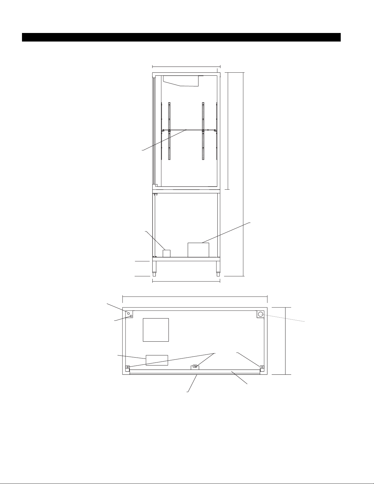
Cut & Plan Views
28 1/8"
1.2” Komacel walls
49"
85 5/16"
ELECTRICAL
WATER SUPPLY
TO HAND VALVE
BALLAST & TERMINAL
BLOCKS
BALLAST
6”
28"
60" (72")
HUMIDITY SYSTEM
BALLAST LOCATION
T5 LAMP
HUMIDITY SYSTEM
DRAIN
28 1/8"
SLIDING DBL-PANE
GLASS DOOR
44.5" X 54" (44.5" X 66")
4
Page 5
Rev. 0904
NSF Installation Requirement
PER NSF INSTALLATION REQUIREMENT
SEAL AROUND CASE TO BASE PERIMETER
WITH NSF APPROVED SEALANT
5
Page 6

Installation
LOCATION
The refrigerated merchandisers have been designed for
use only in air conditioned stores where temperature and
humidity are maintained at or below 75°F and 55% rela-
tive humidity. DO NOT allow air conditioning, electric fans,
ovens, open doors or windows (etc.) to create air currents around the merchandiser, as this will impair its correct operation.
Product temperature should always be maintained at a
constant and proper temperature. This means that from
the time the product is received, through storage, preparation and display, the temperature of the product must
be controlled to maximize life of the product.
Plumbing
IGUP-AB-0904
UNCRATING THE STAND
Place the fixture as close to its permanent position as
possible. Remove the top of the crate. Detach the walls
from each other and remove from the skid. Unbolt the
case from the skid. The fixture can now be lifted off the
crate skid. Lift only at base of stand!
EXTERIOR LOADING
These models have not been structurally designed to sup-
port excessive external loading. Do not walk on their
tops; This could cause serious personal injury and damage to the fixture.
DO NOT SEAL JOINT T RIM T O FLOOR!
WASTE OUTLET AND P-TRAP
The waste outlet is located off the center of the case on
one side allowing drip piping to be run lengthwise under
the fixture.
A P-trap must be installed to prevent air leakage and insect entrance into the fixture. (P-traps are not supplied
with these cases.)
NOTE: PVC-DWV solvent cement is recommended.
Follow the manufacturer’s instructions.
INSTALLING CONDENSATE DRAIN
Poorly or improperly installed condensate drains can seriously interfere with the operation of this refrigerator,
and result in costly maintenance and product losses. Please
follow the recommendations listed below when installing
condensate drains to insure a proper installation:
1. Never use pipe for condensate drains smaller than
the nominal diameter of the pipe or P-trap supplied
with the case.
2. When connecting condensate drains, the P-trap
must be used as part of the condensate drain to
prevent air leakage or insect entrance. Store plumbing system floor drains should be at least 14" off the
center of the case to allow use of the P-trap pipe
section. Never use two water seals in series in any
one line. Double P-traps in series will cause a lock
and prevent draining.
3. Always provide as much down hill slope (“fall”) as
possible; 1/8" per foot is the preferred minimum.
PVC pipe, when used, must be supported to maintain the 1/8" pitch and to prevent warping.
4. Avoid long runs of condensate drains. Long runs
make it impossible to provide the “fall” necessary for
good drainage.
5. Provide a suitable air break between the flood rim of
the floor drain and outlet of condensate drain. 1" is
ideal.
6. Prevent condensate drains from freezing:
a. Do not install condensate drains in contact with
non-insulated suction lines. Suction lines should be
insulated with a nonabsorbent insulation material
such as Armstrong’s Armaflex.
b. Where condensate drains are located in dead air
spaces (between refrigerators or between a
refrigerator and a wall), provide means to prevent
freezing. The water seal should be insulated to
prevent condensation.
6
Page 7

Rev. 0904
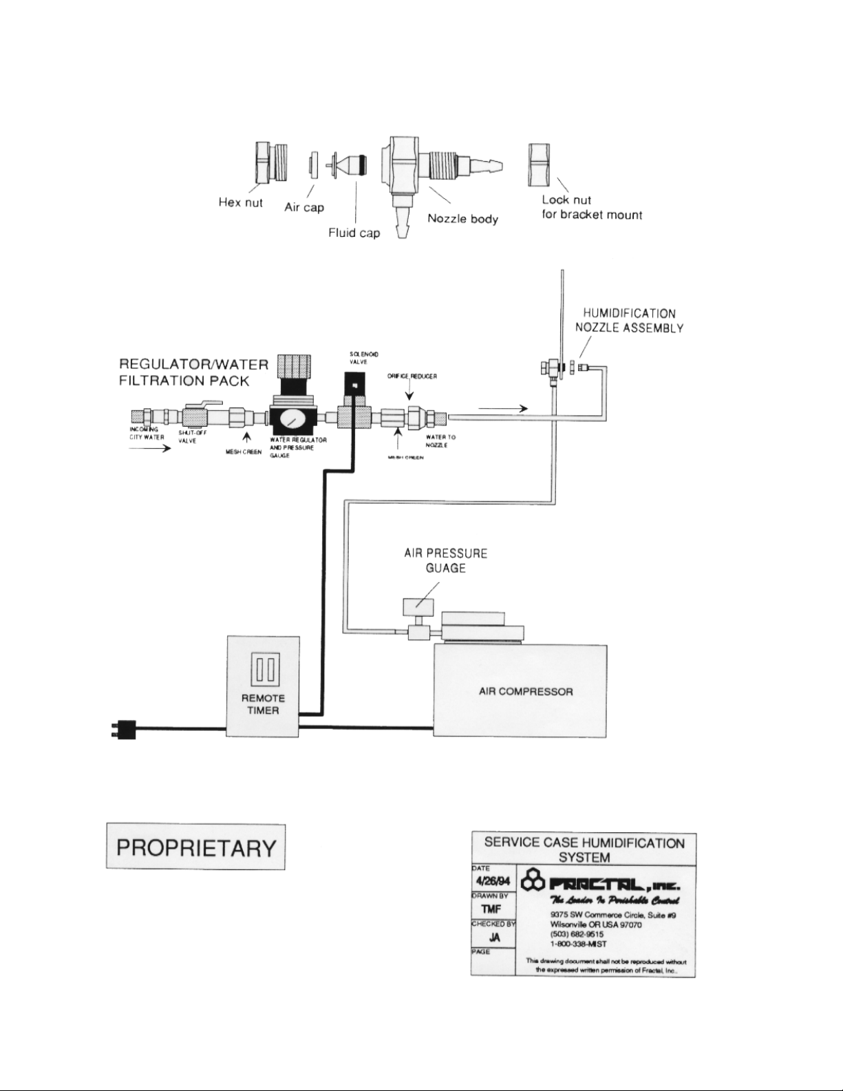
Fractal Humidity System
GENERAL INFORMATION
The Service Case Humidification system is an automatic
moisture maintenance system designed to raise humidity
levels in any new or existing service case counter or
refrigerated floral display. It delivers a damp fog into the
service case or floral display at selected intervals by using
a combination of air and water.
The system consists of a humidification nozzle assembly,
water filtration/regulator unit, remote timer, and air
compressor unit (see attached diagram).
PLEASE READ ALL INSTRUCTIONS BEFORE
BEGINNING INSTALLATION
1. Installation of Regulator Assembly and water hookup
Procedure a. Tie into the water supply line under or near the
service case or floral display by using either a
compression or sweat “Tee” fitting with a 1/2"
FPT. (In cases of new store construction, the
appropriate 1/2" FPT fitting may already be
stubbed up under the case).
b. Screw the provided 1/4" x 1/2" MPT gray plastic
push-in filing into the 1/2" FPT water fitting.
c. To connect tubing for water, push one end of the
1/4" black poly tubing into the plastic push-in
fitting at the Tee”. Measure and cut tubing to
length and insert the opposite end of tubing into
the 1/4" push-in fitting on the Regulator
Assembly marked “CITY WATER”.
d. Connect another length of black poly tubing to
the push-in fitting (or plastic push-in “Tee” for
SCH-2) labeled ‘WATER” on the Regulator
Assembly. Measure and cut this piece of tubing to
length and connect the opposite end to the
push-in elbow fitting on the back of the nozzle
assembly. It may be necessary to drill access
holes through the bottom of the case for the
tubing lines - if so, ensure these holes are sealed
with silicon or similar substance.
TECHNICAL PROCEDURES ARE NOW COMPLETE
2. Start-up, Testing and Adjustment Procedures
a. Turn water on. Pressure gauge on Regulator
Assemblies should read approximately 1-4 psi.
b. Set Timer at each station for a 60 second “On
Time” and I minute “Off Time” cycle. (SEE
ATTACHED CONTROLLER SETTING
INSTRUCTIONS!) This setting, is for testing, on]
and will allow enough time for the water to 1111
the line and reach the nozzle.
c. Plug in the Controller to the 115V outlet.
Compressor and solenoid valves will activate and
plumes from nozzles will independently appear
shortly thereafter.
d. If humidity plume is too light or too heavy. Adjust
the Regulator accordingly. Adjust water pressure
by lifting up the yellow locking cap on the top of
the Regulator and turn clockwise (to increase
pressure) or counter- clockwise (to decrease
pressure). Make Regulator adjustments ONLY
when system is running. Push down on cap to
relock the regulator on the desired pressure.
e. A desired setting would be a pressure that
provides a solid constant plume from the
nozzle(s), but shuts off cleanly when the cycle
ends. If the nozzle(s) continue to emit a stream
of water or drip at shut-off, the pressure should
be decreased.
f. On completion of testing/adjustment, reset
Controller to recommended “On/Off ’ settings
as per Owner’s Guide which is included in the
packing carton.
g. Carry out training on tip cleaning and Timer
settings with department manager and/or staff.
3.
Warranty Conditions -
The SCH system carries a 1 year limited Parts Only
warranty. Fractal Inc. will replace component parts that
are found to be defective through normal operation or
workmanship during manufacture.
b. Performance problems that are directly related
to poor water quality are not the responsibility
of the manufacturer.
THE MANUFACTURER WILL NOT BE RESPONSIBLE
FOR EQUIPMENT PERFORMANCE PROBLEMS
(DURING OR AFTER INSTALLATION). IF
INSTALLATION, ADJUSTMENT, AND TRAINING IS
NOT CARRIED OUT IN ACCORDANCE WITH THESE
INSTRUCTIONS. INSTALLING CONTRACTORS
SHOULD BE AWARE THAT 24 HOUR SERVICE
ASSISTANCE IS AVAILABLE BY CALLING THE
ABOVE TELEPHONE NUMBERS.
7
Page 8
IGUP-AB-0904
8
Page 9
Rev. 0904
Recommended operation times: You should adjust your
humidification time for your stores needs~ This is because
each service case and floral display differs in temperature,
humidity, case style and volume. See chart below for sample
timings,
APPLICATION OFF TIME ON TIME
Seafood 5 min 30 sec
Meat 5 min 30 sec.
Deli 10 min. 30 sec.
Floral 10 min. 60 sec
Humidification nozzle assembly:
The humidification nozzle assembly is typically located at
one end of the service case aimed towards the opposite
end. The humidification nozzle is specially designed to
precisely mix air and water providing the desired humidity
level.
System maintenance and cleaning: (See also
attached Cleaning Instructions) It is recommended
that you clean the humidification nozzle (tip) periodically,
especially in areas with water that contain a high content
of solids. Unscrew the hex nut and remove the air and
fluid caps from the main nozzle body, Soak the caps in a
hot water and Efferdent@ solution for approximately 20
minutes, rinse and replace.
Remote timer operation; (See also cdtached Timer
Setting Instructions) The remote timer has two dials
used for setting times. The dial labeled “T ON” represents
the amount of time the operating cycle is to remain on.
Each number equals one minute, The dial labeled “T OFF”
represents the delay between operating cycles. Each
number equals one minute. Example: If you want two
minutes of mist every ten minutes, set the dial labeled “T
ON” at 2 and set the dial labeled “T OFF” of 10.
Tr oubleshooting:
See attached drawings and helpful tips, however should any
further assistance be required, please call Fractal Inc, Service
Dept. at 1-800-338 6478.
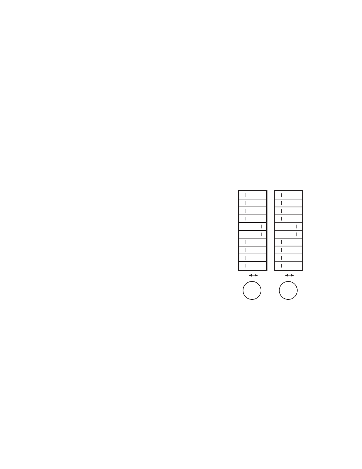
CONTROLLER SETTINGS
FOR SERVICE CASE HUMIDIFICATION SYSTEM
MODELS SCH1/SCH2 - SINGLE STATION
The SCH controller should be installed using the suggested
factory settings for the mist
“OnTime” and “Off Time” as outlined in the Owner’s Guide.
However, it is up to the department manager’s discretion to
adjust these settings to best suit each application. The left
column of switches controls “Off Time” in minutes and the
right column of switches controls “On Time” time in seconds.
2. To adjust mist “OFF TIME”: Set the desired
interval of Mist by sliding the appropriate numbered
switch to the right, or “On” position.
NOTES:
1. To delete previous settings, slide switches back to
the left or “Off” position.
2. Numbers can be combined for total time “On” or
“Off” by sliding more than one switch to the “On”
position. Power light should be illuminated at all
times when power is connected.
4. “On Cycle” light will illuminate only during Misting
cycle.
5. For manual operation or for testing, slide switch
marked “Test” to the “On” position and slide all
other switches to the “Off” position.
OFF TIME
IN MINUTES
TEST
ON TIME
IN MINUTES
1
2
4
1
3
5
10
21
48
85
OFF ON
POWER
WARNING: Controller must be properly
grounded to ensure proper operation. Electrical
power must be disconnected prior to hook-up or
service. Follow all applicable local electrical codes.
FOR SERVICE:
Call your local Authorized Service Agency or contact:
FRACTAL INC.
9375 SW Commerce Circle #9
Wilsonville, OR 97070
(503) 682-9515
(800) 338-MIST (6478)
OFF ON
POWER
8
16
32
64
128
256
512
1. To adjust mist “ON TIME”: Set the desired
length of Mist by sliding the appropriate numbered
switch to the right, or “On” position.
9
Page 10

IGUP-AB-0904
MODELS “SCH & SCHMS” - EMITTER NOZZLE CLEANING INSTRUCTIONS
If the nozzle appears plugged or seems to sputter, it may be that some particles or mineral buildup has occurred in the
fluid body of orifice. Follow these simple instructions to solve the problem. Also, depending on the quality of the local
water supply, regular cleaning should be carried out as a matter of course.
Step 1: Unplug the controller
Step 2: Bracing the nozzle body with one hand, carefully loosen the hex nut Cap on the front of the emitter nozzle,
and remove (be careful not to lose the Air Cap when you remove the Hex Nut).
Step 3. Remove the fluid Body from the nozzle body and look through it towards a light. If you cannot see daylight,
simply rinse under a hot water and blow through the orifice until the blockage is cleared. For more severe mineral
deposits, soak the Fluid Body in an Efferdent solution for approximately 15 minutes, rinsing afterwards. Do Not
insert needles or similar sharp points into the orifice as this will enlarge the size and affect spray performance.
Step 4: Replace the Fluid Body back into the main body (black “O” ring end in first).
Step 5 Making sure the Air Cap is sitting flush inside, screw on the Hex Nut and tighten
Step 6: Plug in controller
10
Page 11

Rev. 0904
Humidity System, Cont’d
TROUBLE SHOOTING GUIDE
Problem Possible Cause / Remedy
Compressor not running • Loss of power to controller.
Check 110V supply and in-store
breaker.
• Loss of power to compressor.
Check for loose wires on controller
module.
No Humidity Plume • Water turned off. Check main
water supply to regulator unit.
• Water tubing contacting ice/
frozen product. Thaw and insulate.
• Solenoid valve not opening.
Check 11OV power from controller.
• Water pressure too low. Adjust
regulator while system is running.
• Tubing lines blocked or kinked.
Check and repair.
• Air pressure escaping. Check air
line for leaks (air pressure should
be 25 PSI).
• No water getting to nozzle.
Remove and clean orifice reducing
plate in regulator assembly.
MAJOR SYSTEM COMPONENTS
PART # DESCRIPTION
10263 Air Compressor
10578 1/8” 110V Mini Solenoid Valve
10762 Timer Module ( Pin plug-in)
10264 8 Pin Base
10193 110V Relay
10024 1/4” Brass Shutoff Valve
10904/l/4/15lbs Pressure Gauge
10716 Water Regulator
SCHNOZSA Nozzle Sub-Assembly
SCHBRKTSA Bracket Mounted nozzzle Sub-
Assemblr
SCHVSA Valve / Regulator Sub-Asembly
(Water filtration Pack)
SCHTSA Complete Timer Sub assembly
Too much / Too Little • Adjust controller settings. Shorten
“Mist On” time or increase “Mist
Off” time.
Moisture • Adjust water pressure.
11
Page 12

Refrigeration
REFRIGERANT TYPE
The standard refrigerant will be R-22 unless otherwise
specified on the customer order. Check the serial plate
on the case for information.
REFRIGERATION LINES
LIQUID SUCTION
3/8" O.D. 5/8" O.D.
NOTE: The standard coil is piped at 5/8" (suction); however,
the store tie-in may vary depending on the number of
coils and the draw the case has. Depending on the case
setup, the connecting point in the store may be
5
/8", 7/8", or 11/8". Refer to the particular case you are
hooking up.
Refrigerant lines should be sized as shown on the refrigeration legend furnished by the store.
Install P-traps (oil traps) at the base of all suction line vertical risers.
Pressure drop can rob the system of capacity. To keep the
pressure drop to a minimum, keep refrigerant line run as
short as possible, using the minimum number of elbows.
Where elbows are required, use long radius elbows only.
CONTROL SETTINGS
See the “Case Specs” section of this guidebook for the
appropriate settings for your merchandiser. Maintain these
parameters to achieve near constant product temperatures. Product temperature should be measured first thing
in the morning, after having been refrigerated overnight.
For all multiplexing, defrost should be time terminated.
Loadmaster valves are not recommended. Defrost times
should as directed in the Case Specifications section of
this guide. The number of defrosts per day should never
change. The duration of the defrost cycle may be adjusted
to meet conditions present at your location.
ACCESS TO TX VALVES & DRAIN LINES
MECHANICAL - Remove product from end of case. Remove
product racks. Remove refrigeration and drain access panels
(labeled). TX valve (mechanical only) and drain are located
under each access panel at end of the case.
ELECTRONIC - The Electronic Expansion valve master and
slave cylinder(s) are located within the electrical access
panel(s).
ELECTRONIC EXPANSION VALVE (OPTIONAL)
A wide variety of electronic expansion valves and case
controllers can be utilized. Please refer to EEV and controller manufacturers information sheet. Sensors for electronic expansion valves will be installed on the coil inlet,
coil outlet, and in the discharge air. (Some supermarkets
require a 4th sensor in the return air). Case controllers
will be located in the electrical raceway or under the case
IGUP-AB-0904
THERMOSTATIC EXPANSION VALVE LOCATION
This device is located on the same side as the refrigeration stub. A Sporlan balanced port expansion valve model
is furnished as standard equipment, unless otherwise specified by customer.
EXPANSION VALVE ADJUSTMENT
Expansion valves must be adjusted to fully feed the evaporator. Before attempting any adjustments, make sure the
evaporator is either clear or very lightly covered with frost,
and that the fixture is within 10°F of its expected operat-
ing temperature.
MEASURING THE OPERATING SUPERHEAT
1. Determine the suction pressure with an accurate
pressure gauge at the evaporator outlet.
2. From a refrigerant pressure temperature chart,
determine the saturation temperature at the
observed suction pressure.
3. Measure the temperature of the suction gas at the
thermostatic remote bulb location.
4. Subtract the saturation temperature obtained in step
No. 2 from the temperature measured in step No. 3.
3. The difference is superheat.
5. Set the superheat for 5°F - 7°F.
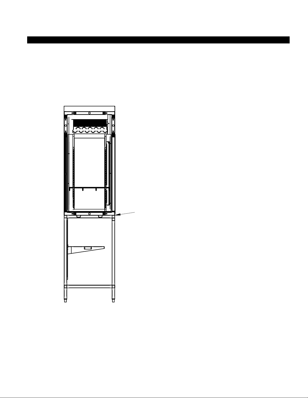
T-STAT LOCATION
T- Stats are located within the electrical raceway. Refer to
diagram below.
ELECTRICAL
WATER SUPPLY
TO HAND VALVE
BALLAST & TERMINAL
BLOCKS
HUMIDITY SYSTEM
BALLAST LOCATION
DRAIN
T5 LAMP
12
Page 13

Rev. 0904
Electrical
WIRING COLOR CODE
CODIGO DE COLORES DE LOS ALAMBRES PARA LAS VITRINAS ESTANDAR
Color Description Descripcion Descripcion
GROUND TIERRA MASA MASSE
ANTI-SWEAT ANTICONDENSCION ANTI-SUINTEMENT
LIGHTS LUCES ECLAIRAGE
RECEPTACLES ENCHUFER RECEPTACLE
T-STAT/SOLENOID 230 V THERMOSTATO / SOLENOID (230 VAC) SOUPAPE A SOLENOID (230 V)
T-STAT/SOLENOID 115 V THERMOSTATO / SOLENOID (115 VAC) SOUPAPE A SOLENOID (115 V)
FAN MOTORS VENTILADORES VENTILATEUR
STANDARD CASE WIRE COLOR CODE
CODE COULEUR POUR FILS DE BOITIER NORMALISE
430-01-0338 r9908
CASE MUST BE GROUNDED
NOTE: Refer to label illustrated above that is affixed to case to
determine the actual configuration as checked in the “TYPE
INSTALLED” boxes.
ELECTRICAL CIRCUIT IDENTIFICATION
Standard lighting for all models will be full length fluorescent lamps located within the case at the top.
The switch controlling the lights, the plug provided for
digital scale, and the thermometer are located at the rear
of the case mullion.
ELECTRICAL SERVICE RECEPTACLES
(WHEN APPLICABLE)
The receptacle that is provided on the exterior back of
these models is intended for computerized scales with a
fifteen amp maximum load, not for large motors or other
high wattage appliances. It should be wired to a dedicated
circuit.
BEFORE SERVICING
ALWAYS DISCONNECT ELECTRICAL
POWER AT THE MAIN DISCONNECT
WHEN SERVICING OR REPLACING ANY
ELECTRICAL COMPONENT.
This includes (but not limited to) Fans, Heat-
ers, Thermostats, and Lights.
less than specified. Field wiring from the refrigeration
control panel to the merchandisers is required for refrigeration thermostats. Most component amperes are
listed in the “Case Specs” section, but always check the
serial plate.
BALLAST LOCATION
Ballasts are located within the access panel that runs
the length of the rear of the case. Refer to diagram on
page 6.
WIRING & SERIAL PLATE AMPERAGE
Field Wiring must be sized for component amperes
stamped on the serial plate. Actual ampere draw may be
less than specified. Field wiring from the refrigeration con
trol panel to the merchandisers is required for refrigeration thermostats. Most component amperes are listed in
the "Case Specs" section, but always check the serial plate.
ASHRAE COLOR CODE
NOTE: All other manufacturers have no standard sensor codes.
Case Control Systems
Manufacturer ® > EIL CP
Location
Coil Inlet
Coil Outlet
Discharge Air
Return Air
Defrost Term.
Liquid Line
SENSOR COLOR
Color
Part#
Color
Part#
Color
Part#
Color
Part#
Color
Part#
Color
Part#
Blue Blue
225-01-1755 225-01-3255
Red Red
225-01-1757 225-01-3123
Green Green
225-01-1756 225-01-3260
Purple Green
225-01-1758 225-01-3260
White Orange
225-01-0650 225-01-3254
White Blue
225-01-0650 225-01-3255
FIELD WIRING & SERIAL PLATE AMPERAGE
Field Wiring must be sized for component amperes
printed on the serial plate. Actual ampere draw may be
13
Page 14

User Information
NON-GLARE GLASS
The high optical clarity of this glas is possible due to sepcial
coatings on the glass surface itself. To preserve this coating
and the optical clarity, keep the glass clean.
Windex
®
or Glass Plus® are the only solutions
recommended to be used to clean the non-glare glass.
The damage to the glass from improper, caustic solutions
is irrepairable.
In addition to cleaning the glass with the recommended
product, there are precautions that should be taken when
working and cleaning the inside of the case.
•When cleaning the inside of the cases, we recommend
that the glass be fully opened and covered to
prevent solutions from splashing onto the glass and
ruining the coating on the inside.
IGUP-AB-0904
14
Page 15

Rev. 0904
User Information, Cont’d
15
Page 16

Maintenance
ELECTRICAL PRECAUTIONS
BEFORE SERVICING – Always disconnect
electrical power at the main disconnect when
servicing or replacing any electrical component
This includes (but not limited to) Fans, Heaters,
Thermostats, and Lights.
REPLACING FLUORESCENT LAMPS
Fluorescent lamps are furnished with a shatterproof protective coating. The same type of lamp with protective
coating must be used if replaced.
This lamp has been treated to resist breakage and must be
replaced with a similarly treated lamp in order to maintain
compliance with NSF Standards. NSF CODE 4.28.1
Contact HUSSMANN Chino for replacement
1-800-395-9229 x 2131
IGUP-AB-0904
MOTOR.
COPPER COILS
The copper coils used in Hussmann merchandisers may
be repaired in the field. Materials are available from local
refrigeration wholesalers.
Hussmann recommends using #15 Sil-Fos for repairs.
TIPS & TROUBLESHOOTING
Before calling for service, check the following:
1. Check electrical power supply to the equipment for
connection.
2. Check fixture loading. Overstocking case will affect
its proper operation.
3. If frost is collecting on fixture and/or product, check
that Humidity Control is working properly, and that
no outside doors or windows are open—allowing
moisture to enter store.
T- 5 B U LBS
Please note: T-5 lights must be turned off and on after bulb
replacement.
EVAPORATOR FANS
The evaporator fans are located at the center front of
these merchandisers directly beneath the display pans.
Should fans or blades need servicing, always replace fan blades
be sure to have the Case Model and Serial
Number handy. This information is on a plate
FOR PROMPT SERVICE
When contacting the factory,
located on the case itself.
with the raised embossed side of the blade TOWARD THE
Electrical and Refrigeration Specifications
MODEL NUMBER
CASE LENGTH
BTU AVG AIR T-STAT/ TYPE & FREQ.
REQ’D EVAP PROD DISC VELOC CUT IN OF NUMBER & E E FANS STD. Humidity
PER FT. TMP TMP TMP @FPM SETTINGS COIL OF MOTORS DURATION (OPTIONAL) FANS WARMERS LIGHTS System
TEMPERATURE DISCHG. FAN SIZE DEFROST
115 V. ELECTRICAL CIRCUITS
AB
Blower Coil Humidity System
5’ 990 25 34 26 200 35 Forced 4" C-frame 36 min. - 2.5 - .58 3.6
Air ( 3 ) (4)
6' 990 25 34 26 200 35 Forced 4" C-frame 36 min. - 3.5 - .58 3.6
Air ( 5 ) (4)
Gravity Coil HumiditySystem (opt.)
5’ & 6' 360 25 35 25 - 35 Gravity - 90 - - - .58 3.6
(1)
16
Page 17

Rev. 0904
Date:
Project Title:
Drawing No.:
Drawn By:
Assembly: Drawing Title:
Date:
Hussmann Corporation, Int'l.
13770 Ramona Avenue, Chino, CA. 91710
(909)-590-4910 Lic.#: 644406
Revisions:
No. Description: Checked By:
By:
File Location:
Boris Kasrel
BJK
Sheet of
1
1
06.27.00
H:\WireSchematics\NewWiring...\
06.27.00
W0050001
Aged Beef Display Case
AB-5' Remote Wiring Diagram
WH3-120-L64
Ballast
black
~115V - 1.7A
white
Duplex
12GA black
~115V - 3.6A
Suction Solenoid Valve
~115V - .5A
Heatcraft 30
brown
gray
~115V - 2.5A
red
Condensate Evaporator
~115V-1500W-12.5A
MOTOR
yellow
red
F28T5/SPX35
S
T-Stat
WH3-120-L64
Ballast
red
yellow
red
F28T5/SPX35
WH3-120-L64
Ballast
red
yellow
red
F28T5/SPX35
Remote sensing bulb
Humidefier Air Pump
Float
Switch
T-Disk
black
Motor
Motor
Motor
~125V - 15A
1 Revised case lenght 07/11 AEC
Electrical Schematics
17
Page 18

IGUP-AB-0904
Date:
Project Title:
Drawing No.:Drawn By:
Assembly: Drawing Title:
Date:
Hussmann Corporation, Int'l.
13770 Ramona Avenue, Chino, CA. 91710
(909)-590-4910 Lic.#: 644406
Revisions:
No. Description: Checked By:
By:
File Location:
Boris Kasrel
BJK
Sheet of
1
1
06.27.00
H:\WireSchematics\NewWiring...\
06.27.00
W0050002
Aged Beef Display Case, humidified
AB-5' / AB-6' Remote Wiring Diagram
WH3-120-L64
Ballast
black
~115V - 1.7A
white
12GA AWG black
~115V - 3.6A
Suction Solenoid Valve
~115V - .5A
Heatcraft 43
brown
gray
~115V - 3.5A
red
Condensate Evaporator
~115V-1500W-12.5A
MOTOR
yellow
red
F28T5/SPX35
S
T-Stat
WH3-120-L64
Ballast
red
yellow
red
F28T5/SPX35
WH3-120-L64
Ballast
red
yellow
red
F28T5/SPX35
Remote sensing bulb
Humidifier Air Pump
Float
Switch
T-Disk
black
Duplex
Motor
~125V - 15A
Motor
Motor
18
Page 19

Rev. 0904
Date:
Project Title:
Drawing No.:
Drawn By:
Assembly:
Drawing Title:
Date:
Hussmann Corporation, Int'l.
13770 Ramona Avenue, Chino, CA. 91710
(909)-590-4910 Lic.#: 644406
Revisions:
No. Description: Checked By:
By:
File Location:
Boris Kasrel
BJK
Sheet of
07.13.00
H:\WireSchematics\NewWiring...
final
Aged Beef Display - Gravity Coil
W0050003
AB-G, Remote Gravity Coil Case Wiring, use on 4'-5'-6' cases
1
1
WH3-120-L
Ballast
black
~115V - 1.7A
~115V - .5A
gray
red
yellow
red
S
T-Stat
red
yellow
red
red
yellow
red
Remote sensing bulb
black
F28T5/830
Suction Solenoid Valve
white
Ballast
Ballast
Gravity Coil
Duplex - optional
black
~125V - 15A
yellow
F28T5/830
F28T5/830
WH3-120-L
WH3-120-L
19
Page 20

IGUP-AB-0904
Date:
Project Title:
Drawing No.:Drawn By:
Assembly: Drawing Title:
Date:
Hussmann Corporation, Int'l.
13770 Ramona Avenue, Chino, CA. 91710
(909)-590-4910 Lic.#: 644406
Revisions:
No. Description: Checked By:
By:
File Location:
Boris Kasrel
BJK
Sheet of
06.29.00
H:\WireSchematics\NewWiring...
final
Aged Beef Display
W0050004
AB-6' SC, Self Contained
1
1
WH3-120-L64
Ballast
black
~115V - 1.7A
12GA black
~115V - 3.6A
~115V - .5A
Heatcraft 43
brown
gray
~115V - 3.5A
red
MOTOR
yellow
red
S
T-Stat
red
yellow
red
red
yellow
red
Remote sensing bulb
Humidifier Air Pump
black
F28T5/SPX35
F28T5/SPX35
F28T5/SPX35
Suction Solenoid Valve
white
WH3-120-L64
Ballast
WH3-120-L64
Ballast
Duplex
Motor
~125V - 15A
Motor
Motor
20
Page 21

Rev. 0904
Date:
Project Title:
Drawing No.:Drawn By:
Assembly: Drawing Title:
Date:
Hussmann Corporation, Int'l.
13770 Ramona Avenue, Chino, CA. 91710
(909)-590-4910 Lic.#: 644406
Revisions:
No. Description: Checked By:
By:
File Location:
Boris Kasrel
BJK
Sheet of
06.29.00
H:\WireSchematics\NewWiring...
final
Aged Beef Display
W0050004
AB-6' SC, Self Contained
white
black
black
white
black
white
~115V - 9.2A
15A
"A"
Start Capacitor
M
1/4 HP-115V-9.2A
C
ompresso
r Motor
Condencer
Fan
Current Relay
5
2
6
41
T
X
4
N
3
1
2
Paragon Timer
8045-00
R
C
S
Pressure
Safety
T-stat
C
o
n
d
e
n
s
a
t
e
E
v
a
p
or
a
t
or
1000W~115V
Float
Switch
T-Disk
2
2
21
Page 22

Appendices
Appendix A. – Temperature Guidelines
Refrigerated
The refrigerators should be operated according to the
manufacturer’s published engineering specifications for
entering air temperatures for specific equipment applications. Table 1 shows the typical temperature of the air
entering the food zone one hour before the start of
defrost and one hour after defrost for various categories
of refrigerators. Refer to Appendix C for Field Evaluation
Guidelines.
TABLE 1
TYPE OF TYPICAL ENTERING
REFRIGERATOR AIR TEMPERATURE
I. OPEN DISPLAY
A. Non frozen:
1) Meat 28°F
2) Dairy/Deli 32°F
3) Produce
a. Processed 36°F
b. Unprocessed 45°F
B. Frozen 0°F
C. Ice Cream -5°F
II. CLOSED DISPLAY
A. Non frozen:
1) Meat 34°F
2) Dairy/Deli 34°F
3) Produce
a. Processed 36°F
b. Unprocessed 45°F
B. Frozen 0°F
C. Ice Cream -5°F
Single Deck Multi Deck Service Case Reach-In
I. Open Display Styles II. Closed Display Styles
Appendix B. – Application Recommendations
Refrigerated
1.0 Temperature performance is critical for controlling
bacteria growth. Therefore, the following recommendations are included in the standard. They are based
on confirmed field experience over many years.
1.1 The installer is responsible for following the installation instructions and recommendations provided by
the manufacturer for the installation of each individual
type refrigerator.
1.2 Refrigeration piping should be sized according to the
IGUP-AB-0904
equipment manufacturer’s recommendations and installed in accordance with normal refrigeration practices. Refrigeration piping should be insulated according to the manufacturer’s recommendations.
1.3 A clogged waste outlet blocks refrigeration. The
installer is responsible for the proper installation of
the system which dispenses condensate waste through
an air gap into the building indirect waste system.
1.4 The installer should perform a complete start-up
evaluation prior to the loading of food into the
refrigerator, which includes such items as:
a) Initial temperature performance, Coils should be
properly fed with a refrigerant according to
manufacturer’s recommendations.
b) Observation of outside influences such as drafts,
radiant heating from the ceiling and from lamps.
Such influence should be properly corrected or
compensated for.
c) At the same time, checks should be made of the
store dry-bulb and wet-bulb temperatures to
ascertain that they are within the limits prescribed by the manufacturer.
d) Complete start-up procedures should include
checking through a defrost to make certain of its
adequate frequency and length without substantially exceeding the actual needs. This should
include checking the electrical or refrigerant
circuits to make sure that defrosts are correctly
programmed for all the refrigerators connected
to each refrigeration system.
e) Recording instruments should be used to check
performance.
Appendix C. – Field Recommendations Refrigerated
Recommendations for field evaluating the performance
of retail food refrigerators and hot cases
1.0 The most consistent indicator of display refrigerator
performance is temperature of the air entering the
product zone (Refrigerated see Diagram 1, Appendix
A). In practical use, the precise determination of
return air temperature is extremely difficult. Readings of return air temperatures will be variable and
results will be inconsistent. The product temperature
alone is not an indicator of refrigerator performance.
NOTE: Public Health will use the temperature of the
product in determining if the refrigerator will be allowed
to display potentially hazardous food. For the purpose of
this evaluation, product temperature above the FDA
Food Code 1993 temperature for potentially hazardous
food will be the first indication that an evaluation should
be performed. It is expected that all refrigerators will
keep food at the FDA Food Code 1993 temperature for
potentially hazardous food.
1.1 The following recommendations are made for the
purpose of arriving at easily taken and understood
22
Page 23

Rev. 0904
data which, coupled with other observations, may be
used to determined whether a display refrigerator is
working as intended:
a) INSTRUMENT – A stainless steel stem-type ther-
mometer is recommended and it should have a
dial a minimum of 1 inch internal diameter. A test
thermometer scaled only in Celsius or dually
scaled in Celsius and Fahrenheit shall be accurate
to 1°C (1.8°F). Temperature measuring devices
that are scaled only in Fahrenheit shall be accu-
rate to 2°F. The thermometer should be checked
for proper calibration. (It should read 32°F when
the stem is immersed in an ice water bath).
b) LOCATION – The probe or sensing element of
the thermometer should be located in the airstream where the air first enters the display or
storage area, and not more than 1 inch away from
the surface and in the center of the discharge
opening.
c) READING – It should first be determined that the
refrigerator is refrigerating and has operated at
least one hour since the end of the last defrost
period. The thermometer reading should be made
only after it has been allowed to stabilize, i.e.,
maintain a constant reading.
d) OTHER OBSERVATIONS – Other observations
should be made which may indicate operating
problems, such as unsatisfactory product, feel/
appearance.
e) CONCLUSIONS – In the absence of any apparent
undesirable conditions, the refrigerator should be
judged to be operating properly. If it is determined
that such condition is undesirable, i.e., the product is above proper temperature, checks should
be made for the following:
1. Has the refrigerator been loaded with warm
product?
2. Is the product loaded beyond the “Safe Load
Line” markers?
3. Are the return air ducts blocked?
4. Are the entering air ducts blocked?
5. Is a dumped display causing turbulent air flow
and mixing with room air?
6. Are spotlights or other high intensity lighting
directed onto the product?
7. Are there unusual draft conditions (from
heating /air-conditioning ducts, open doors,
etc.)?
8. Is there exposure to direct sunlight?
9. Are display signs blocking or diverting airflow?
10. Are the coils of the refrigerator iced up?
11. Is the store ambient over 75°F, 55% RH as set
forth in ASHRAE Standard 72 and ASHRAE
Standard 117?
12. Are the shelf positions, number, and size
other than recommended by the manufac-
Appendices, Cont’d
turer?
13. Is there an improper application or control
system?
14. Is the evaporator fan motor/blade inoperative?
15. Is the defrost time excessive?
16. Is the defrost termination, thermostat (if used)
set too high?
17. Are the refrigerant controls incorrectly adjusted?
18. Is the air entering the condenser above design
conditions? Are the condenser fins clear of
dirt, dust, etc.?
19. Is there a shortage of refrigerant?
Appendix D. – Recommendations To User Refrigerated
1.0 The manufacturer should provide instructions and
recommendations for proper periodic cleaning. The
user will be responsible for such cleaning, including the
cleaning of low temperature equipment within the
compartment and the cooling coil area(s). Cleaning
practices, particularly with respect to proper refrigerator unloading and warm-up, must be in accordance
with applicable recommendations.
1.1 Cleaning of non frozen food equipment should include
a weekly cleaning of the food compartment as a
minimum to prevent bacteria growth from accumulating. Actual use and products may dictate more frequent cleaning. Circumstances of use and equipment
design must also dictate the frequency of cleaning the
display areas. Weekly washing down of the storage
compartment is also recommended, especially for
equipment subject to drippage of milk or other liquids,
or the collection of vegetable, meat, crumbs, etc. or
other debris or litter. Daily cleaning of the external
areas surrounding the storage or display compartments with detergent and water will keep the equipment presentable and prevent grime buildup.
1.2 Load levels as defined by the manufacturer must be
observed.
1.3 The best preservation is achieved by following these
rules:
a) Buy quality products.
b) Receive perishables from transit equipment at the
ideal temperature for the particular product.
c) Expedite perishables to the store’s storage equip-
ment to avoid unnecessary warm-up and prolonged temperature recovery. Food store refrigerators are not food chillers nor can they reclaim
quality lost through previous mishandling.
d) Care must be taken when cross merchandising
products to ensure that potentially hazardous
vegetable products are not placed in non refrigerated areas.
e) Display and storage equipment doors should be
kept closed during periods of inactivity.
23
Page 24

f) Minimize the transfer time of perishables from
storage to display.
g) Keep meat under refrigeration in meat cutting and
processing area except for the few moments it is
being handled in processing. When a cut or tray of
meat is not to be worked on immediately, the
procedure should call for returning it to refrigeration.
h) Keep tools clean and sanitized. Since mechanical
equipment is used for fresh meat processing, all
such equipment should be cleaned at least daily
and each time a different kind of meat product
comes in contact with the tool or equipment.
i) Make sure that all refrigeration equipment is
installed and adjusted in strict accordance with
the manufacturer’s recommendations.
j) See that all storage and refrigeration equipment is
kept in proper working order by routine maintenance.
\
IGUP-AB-0904
Appendices, Cont’d
24
Page 25

Rev. 0904
25
Page 26

IGUP-AB-0904
Limited Warranty
This warranty is made to the original user at the original installation site and is not transferable.
Hussmann merchandisers are warranted to be free from defect in material and workmanship under normal use and
service for a period of one (1) year from the date of original installation (not to exceed fifteen (15) months from the date of
shipment for the factory). Hussmann Impact
the above criteria. Hussmann’s obligation under this warranty shall be limited to repairing or exchanging any part or parts,
without charge F.O.B. factory or nearest authorized parts depot within said period and which is proven to the satisfaction of
the original manufacturing plant warranty group to be thus defective.
Hussmann covers the entire case or refrigeration product and all its components (except for lamps, driers, fuses, and
other maintenance type replacement parts) for the one (1) year warranty period.
Additionally, Hussmann warrants for a total period of three (3) years all sealed, multi-glass assemblies except those
used in sliding doors on closed meat display cases. If within three (3) years from the date of installation (not to exceed thirtynine (39) months from the date of shipment from factory), it shall be proven to the satisfaction of the originating factory
warranty group that there is impaired visibility through the multi-glass assemblies thereof caused by moisture between the
glasses, the multi-glass assembly will be replaced free of charge, F.O.B. factory. This additional warranty excludes accident,
misuse, or glass breakage.
On Hussmann manufactured self-contained display cases, Hussmann agrees to repair or exchange, at its option, the
original motor/compressor unit only with a motor/compressor of like or of similar design and capacity if it is shown to the
satisfaction of Hussmann that the motor/compressor is inoperative due to defects in factory workmanship or material under
normal use and service as outlined in Hussmann’s “Installation Instructions” which are shipped inside new Hussmann equipment. Hussmann’s sole obligation under this warranty shall be limited to a period not to exceed five years from date of
factory shipment.
On Hussmann refrigeration systems, an additional (4) year extended warranty for the motor/compressor assembly
is available, but must be purchased prior to shipment to be in effect. Hussmann reserves the right to inspect the job site,
installation and reason for failure.
The motor/compressor warranties listed above do not include replacement or repair of controls, relays, capacitors,
overload protectors, valve plates, oil pumps, gaskets or any external part on the motor/compressor replaceable in the field, or
any other part of the refrigeration system or self-contained display case.
THE WARRANTIES TO REPAIR OR REPLACE ABOVE RECITED ARE THE ONLY WARRANTIES, EXPRESS, IMPLIED OR STATUTORY, MADE BY HUSSMANN WITH RESPECT TO THE ABOVE MENTIONED EQUIPMENT, INCLUDING ANY IMPLIED WARRANTY OF MERCHANTABILITY OR FITNESS, AND HUSSMANN NEITHER ASSUMES NOR
AUTHORIZES ANY PERSON TO ASSUME FOR IT, ANY OTHER OBLIGATION OR LIABILITY IN CONNECTION WITH
THE SALE OF SAID EQUIPMENT OR ANY PART THEREOF.
THIS WARRANTY SHALL NOT APPLY TO LOSS OF FOOD OR CONTENTS OF THE EQUIPMENT DUE
TO FAILURE FOR ANY REASON. HUSSMANN SHALL NOT BE LIABLE:
•For payment of labor for any removal or installation of warranted parts;
•For any repair or replacements made without the written consent of Hussmann, or when the equipment is installed or
operated in a manner contrary to the printed instructions covering installation and service which accompanied such
equipment;
•For any damages, delays, or losses, direct or consequential which may arise in connection with such equipment or part
thereof;
•For damages caused by fire, flood, strikes, acts of God or circumstances beyond its control;
•When the equipment is subject to negligence, abuse, misuse or when the serial number of the equipment has been
removed, defaced, or altered;
•When the equipment is operated on low or improper voltages
•When the equipment is put to a use other than normally recommended by Hussmann (i.e. deli case used for fresh
meat);
•When operation of this equipment is impaired due to improper drain installation;
•For payment of refrigerant loss for any reason;
•For costs related to shipping or handling of replacement parts.
Hussmann Corporation, Corporate Headquarters: Bridgeton, Missouri, U.S.A. 63044 August 1, 1998
Modular Coils are warranted for a total of five (5) years based upon
26
Page 27

Rev. 0904
Service Record
Last service date: By:
/Chino
Additional copies of this publication may be obtained by contacting:
Hussmann® Chino
13770 Ramona Avenue • Chino, California 91710
(909) 628-8942 FAX
(909) 590-4910
(800) 395-9229
The MODEL NAME and SERIAL NUMBER is required in order to provide you
with the correct parts and information for your particular unit.
They can be found on a small metal plate on the unit.
Please note them below for future reference.
MODEL:
SERIAL NUMBER:
27
 Loading...