

Page 1
Manual
Installation
& Operation
/Chino
ASCS
REV.0303
DELI, MEAT, FISH SERVICE CASE
ASCS
DELI, MEAT, FISH
SERVICE CASE
P/N IGSV-ASCS-0303
INSTALLATION & OPERATION GUIDE
Page 2

Ta b l e of Contents
IGSV-ASCS-0303
General Instructions
THIS BOOKLET CONTAINS INFORMATION ON:
General Instructions ................................................. 2
Cut & Plan Views ....................................................... 3
Installation ................................................................. 3
LEVELING.............................................................................................................. 4
Plumbing .................................................................... 6
WASTE OUTLET AND P-TRAP .............................................................................. 6
Manifold Flush System ............................................. 7
Humidity System ...................................................... 9
Refrigeration ............................................................. 10
T-STAT LOCATION.................................................................................................. 11
Electrical .................................................................... 12
WIRING COLOR CODE ......................................................................................... 12
ASHRAE COLOR CODE .......................................................................................... 12
Finishing Touches ...................................................... 13
JOINT TRIM........................................................................................................... 13
User Information ...................................................... 14
STOCKING.............................................................................................................. 14
CASE CLEANING.................................................................................................... 14
NON-GLARE GLASS ............................................................................................... 15
PLEXIGLASS and ACRYLIC CARE........................................................................... 15
REPLACING FLUORESCENT LAMPS ....................................................................... 16
Maintenance .............................................................. 16
TIPS and TROUBLESHOOTING .............................................................................. 16
LIFT UP GLASS ..................................................................................................... 17
Electrical and Refrigeration Specifications ............ 19
Electrical Schematics ............................................... 20
Appendices ................................................................ 35
APPENDIX A. – Temperature Guidelines ............................................................ 35
APPENDIX B. – Application Recommendations.................................................. 35
APPENDIX C. – Field Recommendations - ......................................................... 35
APPENDIX D. – Recommendations to user - .................................................... 36
ASCS refrigerated, service deli, meat, fish mechandiser
SHIPPING DAMAGE
All equipment should be thoroughly examined for shipping
damage before and during unloading.
This equipment has been carefully inspected at our factory
and the carrier has assumed responsibility for safe arrival.
If damaged, either apparent or concealed, claim must be
made to the carrier.
APPARENT LOSS OR DAMAGE
If there is an obvious loss or damage, it must be noted on
the freight bill or express receipt and signed by the carrier’s
agent; otherwise, carrier may refuse claim. The carrier will
supply necessary claim forms.
CONCEALED LOSS OR DAMAGE
When loss or damage is not apparent until after equipment
is uncrated, a claim for concealed damage is made. Make
request in writing to carrier for inspection within 15 days,
and retain all packaging. The carrier will supply inspection
report and required claim forms.
SHORTAGES
Check your shipment for any possible shortages of material.
If a shortage should exist and is found to be the
responsibility of Hussmann Chino, notify Hussmann Chino.
If such a shortage involves the carrier, notify the carrier
immediately, and request an inspection. Hussmann Chino
will acknowledge shortages within ten days from receipt
of equipment.
HUSSMANN CHINO PRODUCT CONTROL
The serial number and shipping date of all equipment has
been recorded in Hussmann’s files for warranty and
replacement part purposes. All correspondence pertaining
to warranty or parts ordering must include the serial
number of each piece of equipment involved, in order to
provide the customer with the correct parts.
Keep this booklet with the case at all times for future reference.
/Chino
A publication of
Hussmann® Chino
13770 Ramona Avenue • Chino, California 91710
(909) 628-8942 FAX
(909) 590-4910
(800) 395-9229
The Hussmann warranty is printed on the back
of this guide.
2
Page 3
Rev.0303
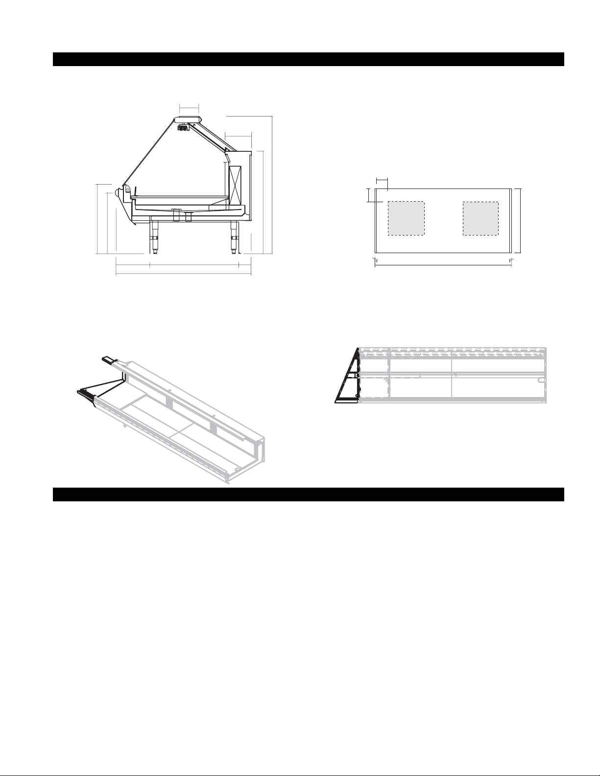
Cut & Plan Views
1
6
/4"
3
8
/4"
"
1
3
0
3
/4"
"
8
"
/
1
3
2
0
2
1
1
/2"
1
Single Deck Refrigerated Service
1
9
2
/2"
5
4
"
ASCS
Scale = 1/2"
1
"
8
/
5
"
5
4
4
3
4
"
11"
1"
8"
MECHANICAL
STUB UP AREA
19" X 19"
DRAIN
CASE FRONT
(VARIABLE LENGTHS)
ASCS
Plan View
Scale = 1/4"
8'-2"
WATER, ELEC.
& REFRIG.
MECHANICAL
STUB UP AREA
19" X 19"
45"
1"
ASC with
22 1/2º Wedge
ASC with 22 1/2º Wedge
Installation
LOCATION
The refrigerated merchandisers have been designed for
use only in air conditioned stores where temperature and
humidity are maintained at or below 75°F and 55% relative
humidity. DO NOT allow air conditioning, electric fans,
ovens, open doors or windows (etc.) to create air currents
around the merchandiser, as this will impair its correct
operation.
Product temperature should always be maintained at a
constant and proper temperature. This means that from
the time the product is received, through storage,
preparation and display, the temperature of the product
must be controlled to maximize life of the product.
UNCRATING THE STAND
Place the fixture as close to its permanent position as
possible. Keep in place, attached case until ready to set/
bolt to adjoining case.
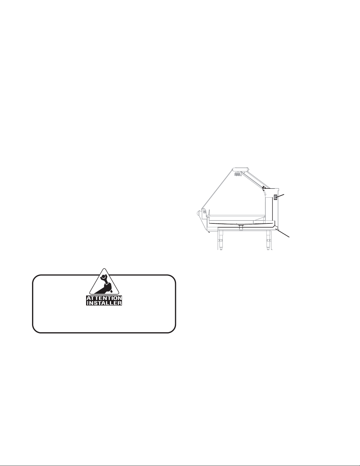
TIGHTEN GLASS SCREWS
Tighten screws along clamshell located on the underside
of glass before placing unit into operation.
EXTERIOR LOADING
These models have not been structurally designed to
support excessive external loading. Do not walk on their
tops. This could cause serious personal injury and damage
to the fixture.
SETTING AND JOINING
The sectional construction of these models enable them
to be joined in line to give the effect of one continuous
display. A joint trim kit is supplied with each joint.
3
Page 4
Installation (continued)
IGSV-ASCS-0303
LEVELING
Important! It is imperative that cases be
leveled from front to back and side to side
prior to joining. A level case is necessary to
insure proper operation, water drainage,
glass alignment, and operation of the hinges
supporting the glass. Leveling the case
correctly will solve all hinge operation and
glass alignment problems.
NOTE: A. To avoid removing concrete flooring, begin lineup
leveling from the highest point of the store floor.
B. When wedges are involved in a lineup, set them first.
All cases were leveled and joined prior to shipment to
insure the closest possible fit when cases are joined in the
field. When joining, use a carpenters level and adjust legs
accordingly. The legs on the ASCS are adjustable and do
not require shims. Simply screw the leg up or down to
adjust height.
1. Using case blueprints, measure off and mark on the
floor the exact dimensions of where the cases will sit.
Snap chalk line for front and back positions of base rail
or pedestal. Mark the location of each joint front and
back. Find the highest point throughout the lineup.
FLOORS ARE NORMALLY NOT LEVEL! Determine
the highest point of the floor; cases will be set off this
point. All cases in the entire lineup must be brought
up to the highest level of the case sitting at the highest
point in the lineup. This may be done a few different
ways. 1) Walk the floor looking for any mounds or dips.
2) Use a string level. 3) Use a transit. If a wedge is used
in the middle of a lineup, the wedge must be set on the
highest point on the floor FIRST, with the rest if the
lineup being leveled from it. The ASCS case has
adjustable legs to allow for leveling.
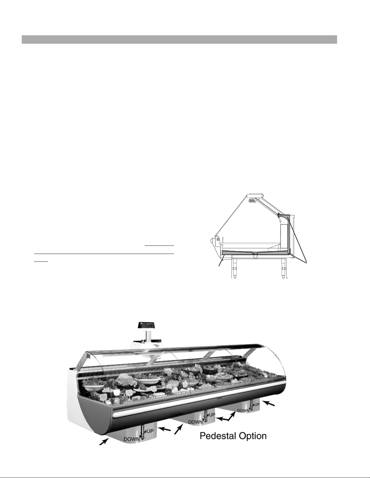
NOTE: The mock pedestal option supplies panels that
clamp on to adjustable legs.
2. Set first case over the highest part of the floor and
adjust legs so that case is level. Remove side and back
leg braces after case is set and joined.
3. Set second case within one foot (1’) of the first case,
and remove end shipping support. Keep the supports
along the length of the case and far end of case. Level
case to the first using the instructions in step one.
4. Apply masking tape 1/8" in from end of case on inside
and outside rear mullion on both cases to be joined.
5. Apply liberal bead of case joint sealant (butyl) to first
case. Sealant area is shown using a dotted line in
illustration in Step 8. Apply heavy amount to cover
entire shaded area.
DO NOT USE PERMAGUM
Butyl
ASCS
Butyl Locations
Butyl
4
Page 5
Rev.0303
Installation (continued)
It is the contractor's responsibility to install
case(s) according to local construction and
health codes.
6. Slide second case up to first case snugly. Then level
second case to the first case so glass front, bumper and
top are flush.
Do not use bolts to pull cases together!
7. To compress butyl at joint, use two Jurgenson wood
clamps. Make sure case is level from front to back and
side to side on inside bulkheads at joint.
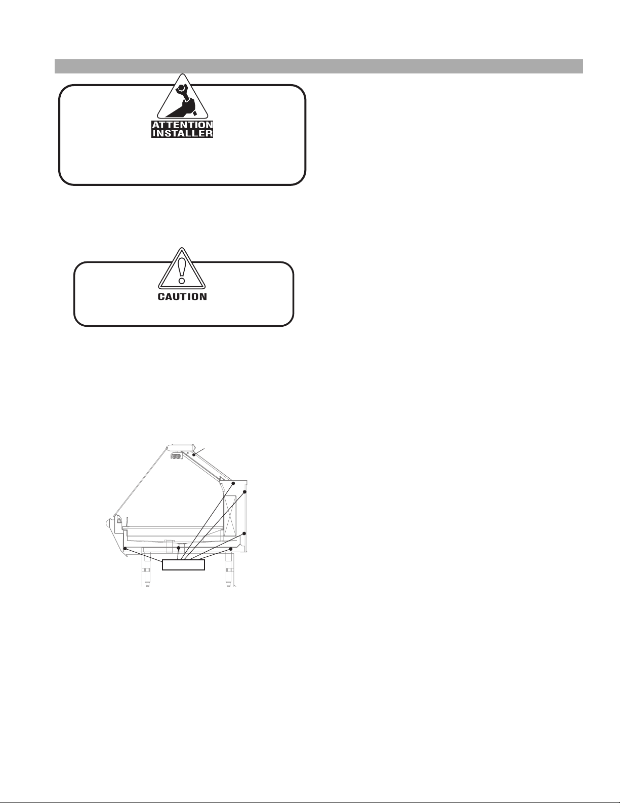
8. Attach sections together via the bolts pictured in the
illustration below.
1/4” Binding Post
5/16” Bolts
ASCS
Bolt Locations
9. Apply bead of butyl to top of bulkheads and slip on
stainless steel bulkhead cap. Also apply silicone to
seam between overhead light tubes.
10. Use finger to smooth silicone as thin as possible at
masking tape on inside and outside of rear mullion
(apply additional silicone if necessary). Remove tape
applied on line #4.
11. Remove front, back and end shipping braces.
INSIDE REFRIGERATED WEDGES
Line up taper pins with holes on adjoining case. Turn
camlock to lock in. Two camlocks are located at the rear
of the case behind the air discharge and behind the lower
electrical raceway access panel. Bolt the wedge into the
adjoining case in the front. If the adjoining case is
refrigerated, the bolt is located under the pans in the front.
When the adjoining case is a hot case, the cases are bolted
together by mans of a bracket located behind the front
panel. Remove the front panel by lifting it up and out..
COMMON END BETWEEN UNLIKE CASES
AND HOT CASES
Bolt the end onto the case using the bolts provided in
predrilled holes behind the front of the panel through the
bracket provided and in the rear behind the rear access
panel on the bottom Common ends between refrigerated
cases are also bolted together behind the air discharge
panel. Remove the discharge panel by lifting up and out.
Hot cases are only bolted in two places, in the rear of the
case, behind the access panel, and in the front of the case
behind the front panel.
OUTSIDE REFRIGERATED WEDGE:
Ta per pin and camlock locations are the same as a standard
case.
INSIDE DRY WEDGES
Bolt the wedge into the sides of the adjoining case. Use
the bolts provided
INSIDE PEDESTAL WEDGES
Set the wedge on adjoining case’s mounting brackets
located at the base of the unit, and bolt down. Drive screws
provided through the sides of the wedge (4 screws per
side), accessible through the back of the wedge.
1. Secure the joint backer located behind the cart
bumper support at the joints. To adjust the front panel.
Loosen the screws holding the bumper on the case on
either side the joint, and slide the extrusion to the
center of the joint.
2. Starting from a center case in a lineup or wedge, align
the front panels. Front panels can be loosened and
adjusted laterally by loosing the screws holding the
case bumper channel.
5
Page 6
ARM STRUT
GUSSET
IGSV-ASCS-0303
Installation (cont.)
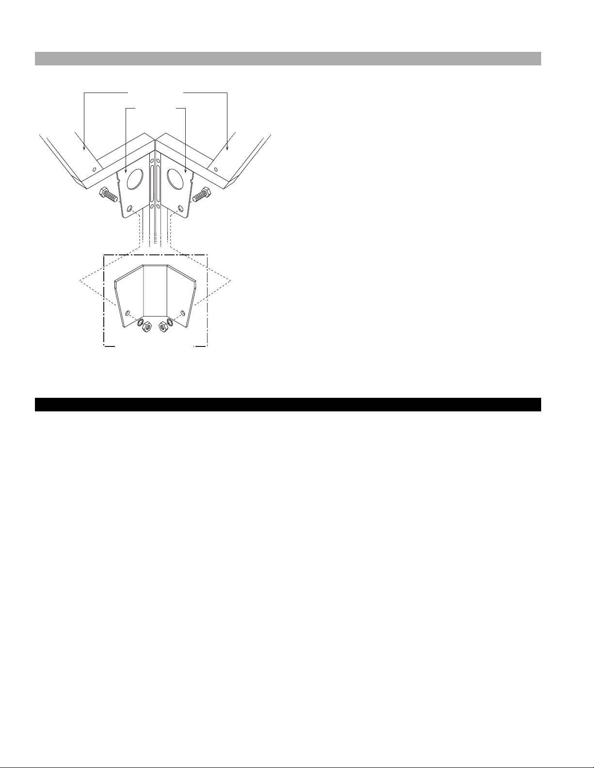
Corner wedges are attached via front and rear camlocks.
Use a 7mm Allen wrench to turn the locks. Do not
overtighten! Join the top by using a joint bracket (included
in joint kit) with 3/8" bolts.
WEDGE BRACKET
Plumbing
WASTE OUTLET AND P-TRAP
The waste outlet is located off the center of the case on
one side allowing drip piping to be run lengthwise under
the fixture.
A 1-1/2" P-trap and threaded adapter are supplied with
each fixture. The P-trap must be installed to prevent air
leakage and insect entrance into the fixture.
NOTE: PVC-DWV solvent cement is recommended.
Follow the Hussmann’s instructions.
INSTALLING CONDENSATE DRAIN
Poorly or improperly installed condensate drains can
seriously interfere with the operation of this refrigerator,
and result in costly maintenance and product losses. Please
follow the recommendations listed below when installing
condensate drains to insure a proper installation:
1. Never use pipe for condensate drains smaller than the
nominal diameter of the pipe or P-trap supplied with
the case.
2. When connecting condensate drains, the P-trap must
be used as part of the condensate drain to prevent air
leakage or insect entrance. Store plumbing system
floor drains should be at least 14" off the center of the
case to allow use of the P-trap pipe section. Never use
two water seals in series in any one line. Double Ptraps in series will cause a lock and prevent draining.
3. Always provide as much down hill slope (“fall”) as
possible; 1/8" per foot is the preferred minimum. PVC
pipe, when used, must be supported to maintain the
1/8" pitch and to prevent warping.
4. Avoid long runs of condensate drains. Long runs make
it impossible to provide the “fall” necessary for good
drainage.
5. Provide a suitable air break between the flood rim of
the floor drain and outlet of condensate drain. 1" is
ideal.
6. Prevent condensate drains from freezing:
a. Do not install condensate drains in contact with
non-insulated suction lines. Suction lines should be
insulated with a nonabsorbent insulation material
such as Armstrong’s Armaflex.
b. Where condensate drains are located in dead air
spaces (between refrigerators or between a
refrigerator and a wall), provide means to prevent
freezing. The water seal should be insulated to
prevent condensation.
6
Page 7
Rev.0303
Manifold Flush System
GENERAL DESCRIPTION
The flush system generates a high pressure water stream
meant to flush most residue buildup from the bottom of
the manifold chamber. This is the area that residue builds
and expands. Frequency of this periodic maintenance will
vary depending on water mineral content and sanitary
conditions.
MANUAL FLUSH SYSTEM
Water valve is located on the outside of the case, in the
rear, on the left hand side as viewed from the rear.
AUTOMATIC FLUSH SYSTEM
Electrical components are located within the electrical
raceway. Electrical components in this area are 115V AC.
Step-down transformer is located in the wireway, and is
controlled by pump switch. Water flow for flush system is
rated at 0.25 GPM at 60 PSI water pressure. Flush nozzle
located in the rear of the case.
BASIC SYSTEM OPERATION:
1. Filtered water is supplied to the 115V solenoid valve.
2. At a time of day determined by you, the 115V time
clock will energize the solenoid for two (2) minutes.
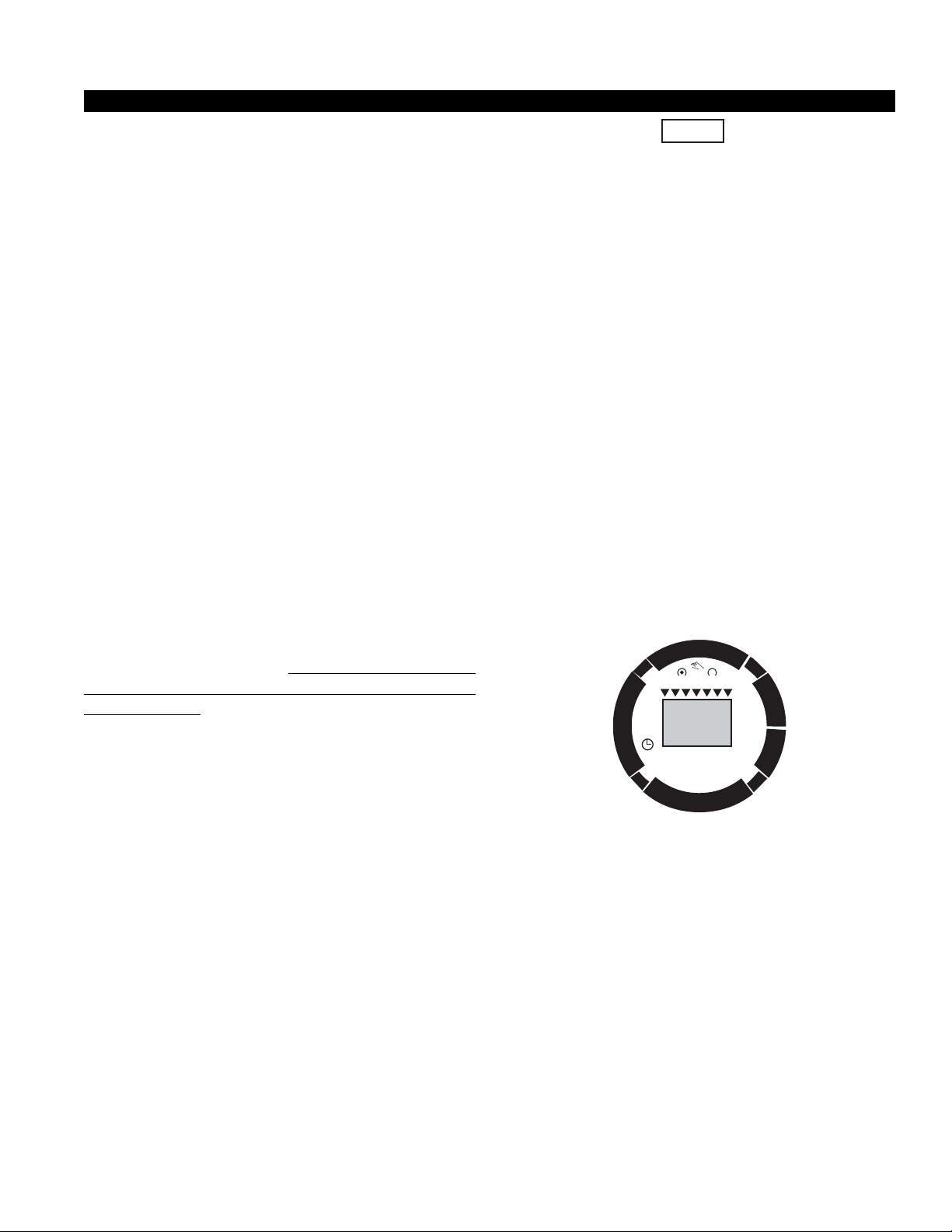
PROGRAMMING THE TIMER
The circular keypads are positioned to provide a sequential
[at for programming. Starting the Prog. button to select a
program clockwise to ON/OFF, h for hour, m for minute,
and finally Day to select the day for days of the week you
wish the flush to operate on. If one of these selections is
omitted, the control will flash when the clock or program
key is depressed. The missing entry must be completed
before the programming can resume.
•A program consists of
1. ON/OFF
2. Hour and minute
3. Day or multiple days on which it is to occur.
• Res. is the reset key and will erase the current
program.
• The ±h key adjusts the set clock time for daylight
savings time.
•Military time (24 hr clock) or 12 hour clock may be
selected by pressing and holding the h key while
depressing the ±h key.
•A flashing light indicated a missing selection in the
program or a low battery. Check to make sure the
timeclock’s program is complete (ON/OFF, time, and
days)
NOTE: If the h and m keys are held down longer than 2
seconds, the numbers will advance rapidly. Press and hold
the (2) day during the following: (If Daylight Savings Time is
In effect, press ±1h first).
1. Press the Prog. key.
1 2 4 5 6 7
AM– –:– –
will appear in display.
2. Press the key between ON/OFF. The word ON will
appear.
3. Press h to select hour for initial system startup.
4. Press m to select the minute the system starts up (30
for 10:30)
5. Select the days desired with the Day key.
1. If the program is to occur every day of the week,
ignore Day and press Prog. key to advance to next
program.
2. If specific, 7 day time control is desired, press Day
and 1-5 will appear for Mon. - Fri. Pressing Day
again will display 6,7 for Sat. and Sun.
6. Press the key between ON/OFF to select the cycle
termination time. The word OFF will appear.
7. Press h to select hour the system terminates.
8. Press m to select the minute the system terminates.
9. Repeat with the days.
10. Press Prog. key and repeat steps 2 thru 11 for
additional defrost schedules.
11. After programming press clock key to enter run
mode.
NOTE: If the days are flashing, it indicates the day of the week was not set
when setting the time. The timer cannot be programmed unless the day of
the week is entered.
±
1
Off
h
r
.
Sa
Su
Fr
h
m
.
g
o
r
P
Ref.
On
Mo Tu We
GRÄSSLIN
Th
Day
START UP:
1. Manually move time clock to initiate a flush cycle.
2. Observe that flush nozzle is spraying down center of
manifold chamber.
3. Set clock to correct time of day.
4. Set trip pins to the “time of day system is to flush”
(NOTE: Two [2] flushes per day!)
7
Page 8
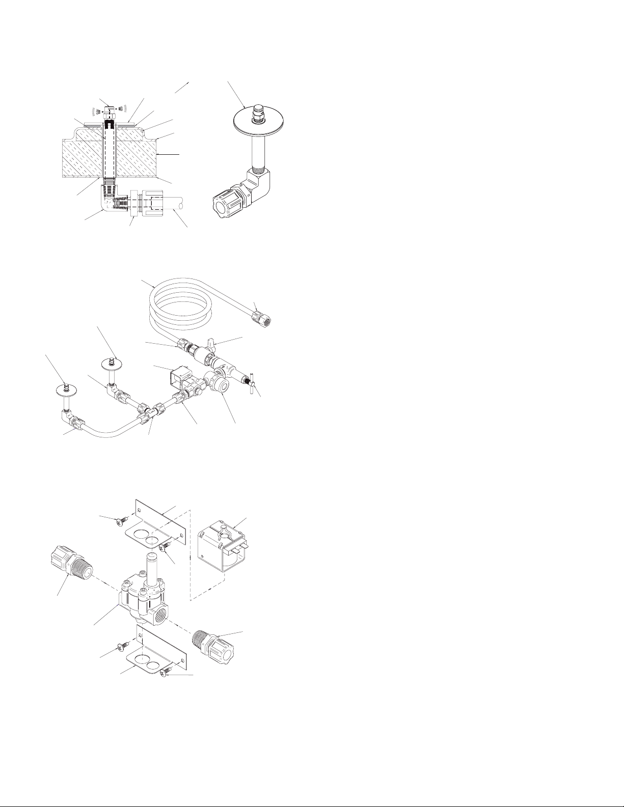
These two components
are now assembly
NOZZLE - MONARCH
Model #: H-545-R2-0.72-360 303SS
# 225-01-2004-SS
NIPPLE (1/2) 3" LONG
304 SS PIPE
# 225-01-0602
USE WASHERS
(IF REQUIRED)
ELBOW 90°
1/4" NPT x 1/4" NPT
# 225-01-0336
WASHER # 038222
PERMAGUM SEAL
COMPRESSION FITTING
PVC - 1/4" NPT x 1/2" OD
# 225-01-1323
part # 225-01-0603
(HOCKEY-POCK SPACER)
POLYURETHANE COAT
INSULATION @
CENTER OF CASE
(FRONT TO BACK)
CASE BOTTOM LINER
(16 GA. GALV)
1/2" OD POLY TUBING
# 225-01-0003
Nozzle and Components with Part Numbers
1/2" OD POLY TUBING
# 225-01-0003
LEAVE AT LEAST 10'
FOR FIELD CONNECTION
WASHER / PIPE ASSEMBLY
304 STAINLESS
# 225-01-0603
NOZZLE - MONARCH
Model #: H-545-R2-0.72-360
303SS
# 225-01-2004-SS
ELBOW 90°- BRASS
1/4" NPT x 1/4" NPT
# 225-01-0336
COMPRESSION FITTING
PVC - 1/2" OD x 1/2" NPT
# 225-01-1322
SOLENOID VALVE
ALCO 222CB- B- B-AMS
# 225-01-1340
COMPRESSION FITTING
PVC - 1/2" OD x 1/2" FPT
# 225-01-1327
(FIELD CONNECTION)
HAND BALL VALVE
PVC - 1/2" FPT - FULL
BORE - # 225-01-2122
IGSV-ASCS-0303
Nozzle count to change
according to case length.
COMPRESSION FITTING
PVC - 1/4" NPT x 1/2" OD
# 225-01-1323
Water Flush Fittings with Part Numbers
#5-32 SELF
TAP SCREW
COMPRESSION FITTING
PVC - 1/2" OD x 1/2" NPT
# 225-01-1322
SOLENOID VALVE BODY
ALCO 222CB- B# 225-01-1340
#5-32 SELF
TAP SCREW
UNION TEE COMPRESSION
PVC - 1/2" OD x 1/2" OD
# 225-01-1324
BRACKET
# 038244
COMPRESSION FITTING
PVC - 1/2" OD x 1/2" NPT
# 225-01-1322
BRACKET
# 038244
#5-32 SELF
TAP SCREW
#5-32 SELF
TAP SCREW
WATER PRESSURE
REGULATOR
SPRAY SYSTEMS CO. 6815-1/2
# 225-01-1403
IN-LINE STRAINER - CLEAR
BOWL - NYLON 1/2" MPT
TEEL 2P131 # 225-01-2133
SOLENOID COIL
ALCO- AMS
COMPRESSION FITTING
PVC - 1/2" OD x 1/2" NPT
# 225-01-1322
Solenoid Valve and Part Numbers
8
Page 9

Rev.0303
Humidity System
GENERAL DESCRIPTION
One contributor to the spoilage of fresh meats is
dehydration, which causes loss in weight and volume
(shrinkage) and product discoloration. As the refrigeration
system removes heat from the case, it also removes critical
moisture from the air, and any unwrapped products in the
case. The Humidity System replaces the moisture in the
air, in order to compensate for the moisture taken by the
refrigeration system, and disposed of down the drain line.
The system is built into the discharge plenum, and mixes
moisture laden air with refrigerated air before the air is
passed through - and around the product.
The system is constructed almost entirely of PVC pipe,
and uses air that is subcooled to approximately the same
temperature as the case. The sub-cooling of air inhibits
the formation of growth found to be a problem in other
humidification systems. Maintenance is almost unnecessary
if you follow a few simple rules:
1. Keep the case clean.
2.Keep the water filter clean, and change it every six
to twelve months or sooner, depending on the kind of
water found in your area.
3. Flush the header every six (6) months, by loosening
the connecting “L”, then removing it from the case, and
flushing with a hose.
**IMPORTANT INFORMATION**
The ASCS is capable of maintaining superb product quality
with the installation of the proper controlling devices. These
devices should be set according to the Hussmann’s
specifications. The humidity system should be properly
maintained. Incorrect settings and failure to maintain the
humidity system will result in short product life. Below
are a few guidelines for optimum performance and product
life:
• Set thermostat to cut in at the discharge temperature
designated in the case specifications section of the
appropriate installation guide or spec. sheet. Maintain
the recommended product temperature for Deli,
Meat, and Fish. DO NOT set temperature too cold, as
this causes product dehydration.
•Temperatures should be achieved by means of a T-Stat
and Suction Solenoid at each case. DO NOT use EPR
valves, Liquid Line Solenoids, or electronic control
devices of any kind. These controls allow temperature
swings that cause dehydration and excessive energy
consumption.
• Set defrost cycles as listed in the Case Specifications
Data for your particular case. The number of defrosts
per day should never change. The duration of the
defrost cycle may be adjusted to meet conditions
present at your location.
•Clean humidity system a minimum of every 90 days for
proper system operation.
•Work and rotate product - not to exceed a four (4)
hour period.
•At night, turn off case lights, and cover unwrapped
product with moistened cheesecloth or fabric towels.
•Keep meat holding box at 32°F.
•Keep meat prep room refrigerated at 55°F.
• Meat Bloom Box (if applicable) should be at 36°F.
• Meat must enter the case at 40°F or below. Product
deteriorates rapidly above 40°F.
•Clean, sanitary conditions are required throughout the
meat holding, prep, and work areas.
• Do not display product directly within the air
discharge
•Turn and rotate meat. The blood works down through
the meat over time, which causes the top surface to
discolor and dehydrate. Turn meat 3-4 times per day.
• It is not required to remove product from case
overnight. Turn off case lights, and cover product with
moistened cheesecloth or fabric towel. This helps slow
down product dehydration, by taking moisture from
the cloth and not the product. This is an old method
used by meat shops for many years, as it extends
product life.
• Cold coils remove heat and moisture from the case
and deposit this as frost onto the coil. Thus a defrost
is required to remove this frost. Our humidity system
induces moisture into the case, and helps slow down
the dehydration process. The only other moisture in
the case is that which is in the product. A single level
of meat will dry out faster than a fully loaded case with
3-4 levels of meat.
• The colder the case, the faster the product loses its
moisture and shelf life. It is very important to maintain
a constant, even, correct, product temperature.
HUMIDIFICATION SYSTEM HOOKUPS
Remove the raceway panel on the lower back of the case.
The pre-piped water shut-off valve and the water filter
are located on the left hand side of the case. The water
line (which is a 1/4" OD copper fitting) can be connected
to the ball shut-off valve, by means of a compression fitting
(supplied). The line should be one size larger than the supply
line. The line can then be run from one case to another
from within the raceway(s) using Tee connectors. Before
connecting the water to the humidity system, it is best to
9
Page 10
Humidity System (cont.)
purge the line to flush any debris that may clog the water
filter. If the water line requires purging after the cases are
hooked together, it is not necessary to check each one.
Simply shut ball valves to each humidity system, remove
the water line from the last case in the flow, and purge. By
doing this as a precautionary measure, you may avoid
problems and repeat servicing.
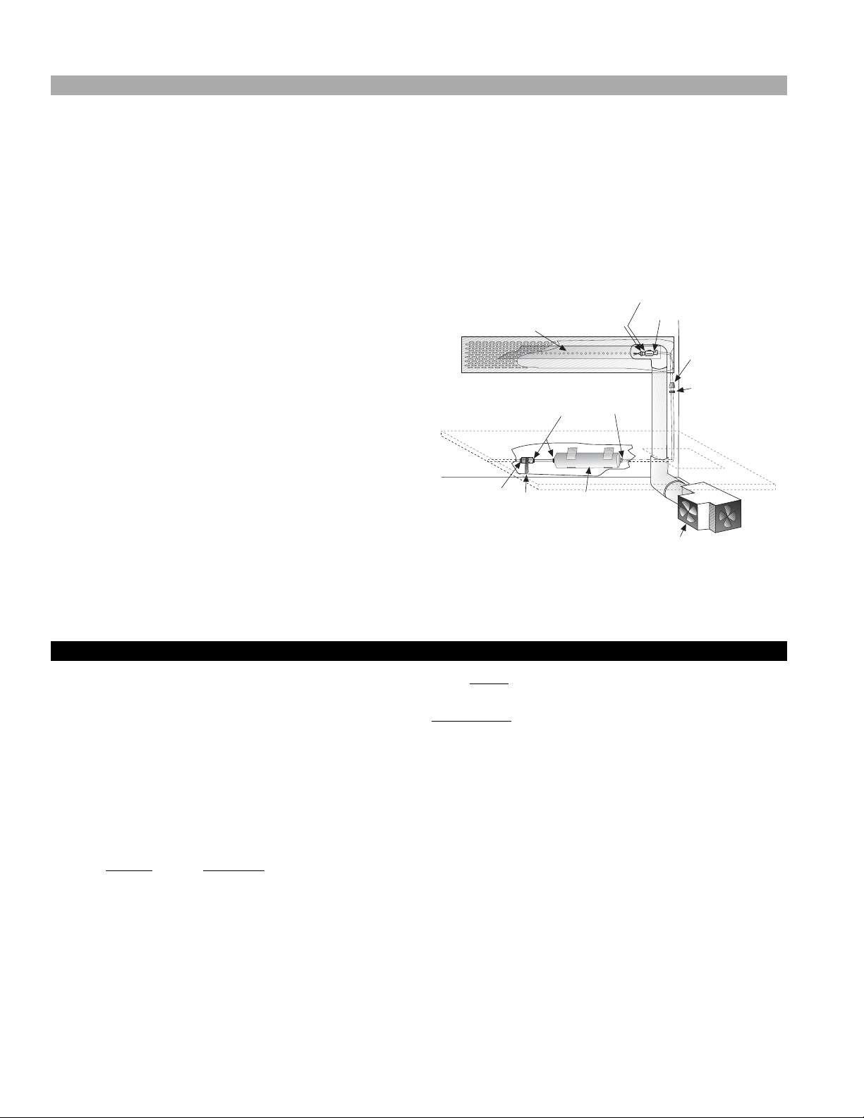
START-UP
Turn on the fan circuit. Check to see if the fan for the
humidity system is running. Remove the right hand bottom
pan (when facing the front of the case), then the TXV cover.
The fan is located up against the right hand side of the
case, as viewed from the front, under the fan plenum (see
diagram). View the blade, and make sure the fan rotation
agrees with the air flow arrows. Turn on the water, by
turning the ball valve in the direction of the flow (OFF is
at 90° to the direction of flow).
After a few minutes, check the spray header by sliding the
honeycomb to the left to expose the discharge tube located
on the right hand side of the case (when viewed from the
rear), by lifting the 4'-0" section of honeycomb with both
ends, until the bottom clears. Pull up and set aside. The
spray header will be exposed. Grasp the header and pull it
loose from the 90° “L” until you see the misting nozzle,
which should be spraying. If not, check the following:
1. Make sure the water is feeding the nozzle.
2. Remove the nozzle, and purge the water.
IGSV-ASCS-0303
3. Check strainer at entrance to nozzle.
Reinsert the header into the 90° “L”, making sure that the
nozzle is in the center of the pipe when totally inserted,
and the holes in the header are facing the front of the case
at a level angle.
The discharge tube can easily be pulled to service.
MAINTENANCE
•Clean humidity system a minimum of every 90 days for
proper system operation.
1/8" 100 X 1/8FPT
SW ADAPTER
225-01-3220
SPRAY HEADER
RUNS LENGTH OF CASE
REAR INTERIOR WALL OF CASE
VIEWED FROM FRONT
WATER
SUPPLY
1/4"MPT X 1/4" OD
COMP ADAPTER
225-01-1312
BALL VALVE
HAMMON
225-01-2026
HAGO-M1 NOZZLE
225-01-3221
1/4"MPT X 1/4" COMP PVC ADAPTER
225-01-2026
WATER FILTER
3 STAGE #00015
225-01-2026
HUMIDITY SYSTEM as viewed from the front.
Note: The axial fans included in the humidity system must be
replaced as a unit.
1/4" 100 X 1/8FPT
SW ADAPTER
225-01-2089A
2ND FAN USED
IN 12' CASE
1/4" OD X 1/8" FPT
SW ADAPTER
225-01-3059
1/8" MPT X 1/4" COMP
PVC ADAPTER
225-01-3059
PAN AND ACCESS PANEL
3" AXIAL FAN
225-01-2026
Refrigeration
REFRIGERANT TYPE
The standard refrigerant will be R-22 unless otherwise
specified on the customer order. Check the serial plate
on the case for information.
PIPING
The refrigerant line outlets are located under the case.
Locate first the electrical box, the outlets are then on the
same side of the case, but at the opposite end. Insulate
suction lines to prevent condensation drippage.
REFRIGERATION LINES
LIQUID SUCTION
1/2" O.D. 5/8" O.D.
NOTE: The standard coil is piped at 5/8" (suction); however,
the store tie-in may vary depending on the number of
coils and the draw the case has. Depending on the case
setup, the connecting point in the store may be
5
/8", 7/8", or 11/8". Refer to the particular case you are
hooking up.
Refrigerant lines should be sized as shown on the
refrigeration legend furnished by the store.
P-traps (oil traps) at the base of all suction line vertical
Install
risers.
Pressure drop can rob the system of capacity. To keep the
pressure drop to a minimum, keep refrigerant line run as
short as possible, using the minimum number of elbows.
Where elbows are required, use long radius elbows only.
CONTROL SETTINGS
See the “Case Specs” section of this guidebook for the
appropriate settings for your merchandiser. Maintain these
parameters to achieve near constant product
temperatures. Product temperature should first be
measured in the morning, after having been refrigerated
overnight. For all multiplexing, defrost should be time
terminated. Defrost length and frequency should as
directed in the Case Specifications section of this guide.
The number of defrosts per day should never change. The
duration of the defrost cycle may be adjusted to meet
conditions present at your location.
10
Page 11
Rev.0303
ACCESS TO TX VALVES AND DRAIN LINES
MECHANICAL - Remove product from case. Remove pans.
TX valve (mechanical only) and drain are located under the
pans within the case.
ELECTRONIC - The electronic expansion valve master and
slave cylinder(s) are located within the electrical access
panel(s) in the rear of case. Rear panels lift up and out.
NOTE: Duplex receptacles must be detached before
removing rear panels.
ELECTRONIC EXPANSION VALVE (OPTIONAL)
A wide variety of electronic expansion valves and case
controllers can be utilized. Please refer to EEV and
controller Hussmann’s information sheet. Sensors for
electronic expansion valves will be installed on the coil
inlet, coil outlet, and in the discharge air. (Some
supermarkets require a 4th sensor in the return air). Case
controllers will be located in the electrical raceway or
under the case.
THREE THERMOSTATIC EXPANSION VALVES
ALCO balanced port expansion valves are furnished as
standard equipment, unless otherwise specified by
customer.
EXPANSION VALVE ADJUSTMENT
Expansion valves must be adjusted to fully feed the
evaporator. Before attempting any adjustments, make sure
the evaporator is either clear or very lightly covered with
frost, and that the fixture is within 10°F of its expected
operating temperature.
pressure gauge at the evaporator outlet.
2. From a refrigerant pressure temperature chart,
determine the saturation temperature at the
observed suction pressure.
3. Measure the temperature of the suction gas at the
thermostatic remote bulb location.
4. Subtract the saturation temperature obtained in step No.
2 from the temperature measured in step No. 3.
3. The difference is superheat.
5. Set the superheat for 5°F - 7°F.
T-STAT LOCATION
T- Stats are located in the electrical section; behind the rear
panel, on the right-hand side of the case (facing the back of
the case).
T-Stat
Electrical Raceway
After case has been brought to
running temperature, tighten glass screws
along clamshell.
MEASURING THE OPERATING SUPERHEAT
1. Determine the suction pressure with an accurate
11
Page 12
Electrical
WIRING COLOR CODE
GREEN GROUND
PURPLE ANTI-SWEAT
ORANGE LIGHTS
YELLOW RECEPTACLE
RED / BLACK T-STAT /SOLENOID230V
BLACK / WHITET-STAT / SOLENOID 115V
BROWN FAN MOTORS
CASE MUST BE GROUNDED
NOTE: Refer to label affixed to case to determine the actual
configuration as checked in the “TYPE INSTALLED” boxes.
ELECTRICAL CIRCUIT IDENTIFICATION
Standard lighting for all models will be full length fluorescent
lamps located within the case at the top.
The switch controlling the lights, the plug provided for digital
scale, and the thermometer are located at the rear of the case
mullion.
The receptacle that is provided on the exterior back of these
models is intended for computerized scales with a five amp
maximum load, not for large motors or other high wattage
appliances. It should be wired to a dedicated circuit.
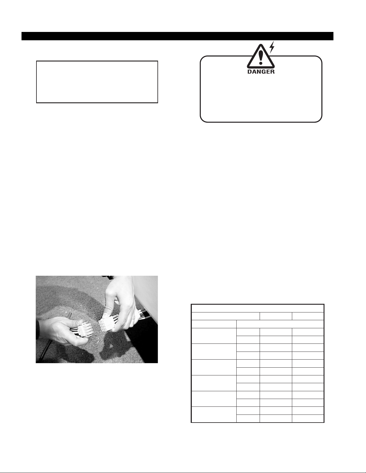
CASE-TO CASE CONNECTORS
HUSSMANN/CHINO now provides “CASE-TO-CASE”
locking electrical connector fittings on the ASCS service cases.
These connectors greatly simplify field installation thereby saving
time and electrical installation costs.
NOTE: The total case electrical draw must not exceed
30 Amps ampacity at 115V in one connected lineup.
IGSV-ASCS-0303
BEFORE SERVICING
Always Disconnect Electrical
Power at the Main Disconnect
when servicing or replacing any
electrical component.
This includes (but not limited to) Fans, Heaters,
Thermostats, and Lights.
FIELD WIRING AND SERIAL PLATE AMPERAGE
Field wiring must be sized for component amperes printed
on the serial plate. Actual ampere draw may be less than
specified. Field wiring from the refrigeration control panel
to the merchandisers is required for refrigeration
thermostats. Most component amperes are listed in the
“Case Specs” section, but always check the serial plate.
BALLAST LOCATION
Ballasts are located within the access panel that runs the
length of the rear of the case. Refer to diagram on page 6.
WIRING AND SERIAL PLATE AMPERAGE
Field wiring must be sized for component amperes stamped
on the serial plate. Actual ampere draw may be less than
specified. Field wiring from the refrigeration control panel to
the merchandisers is required for refrigeration thermostats.
Most component amperes are listed in the "Case Specs" section,
but always check the serial plate.
ELECTRICAL SERVICE RECEPTACLES
(WHEN APPLICABLE)
The receptacles located on the exterior of the
merchandiser are intended for scales and lighted displays.
They are not intended nor suitable for large motors or
other external appliances.
ASHRAE COLOR CODE
NOTE: All other manufacturers; no known sensor codes
Case Control Systems
Manufacturer ® > EIL CPC
Location
Coil Inlet
Coil Outlet
Discharge Air
Return Air
Defrost Term.
Liquid Line
SENSOR COLORS
Color
Part#
Color
Part#
Color
Part#
Color
Part#
Color
Part#
Color
Part#
Blue Blue
225-01-1755 225-01-3255
Red Red
225-01-1757 225-01-3123
Green Green
225-01-1756 225-01-3260
Purple Green
225-01-1758 225-01-3260
White Orange
225-01-0650 225-01-3254
White Blue
225-01-0650 225-01-3255
12
Page 13

Rev.0303
Finishing Touches
JOINT TRIM
After cases have been leveled and joined, and refrigeration,
electrical, and waste piping work completed, install the
splashguards. Fasten along the top edge, or center, with
#10 X 3/3" sheet metal screws.
Joint Trim
Joint Trim
ASCS
Butyl Locations
DO NOT SEAL JOINT T RIM T O FLOOR!
BUMPER INSTALLATION TIPS
1. Start to attach the bumper at one end of the lineup,
preferably on a straight case.
2. Push the end of the bumper into the bumper channel
firmly. This may be difficult if bumper is cold.
3. Bend the bumper backwards to open and guide it
forward onto the bumper channel.
4. An inside bumper miter must be cut on wedges.
5. Loose ends on miters must be anchored with screws
on the bottom edge.
6. The top and bottom edges of the bumper must be
firmly seated into the retainer by applying with a
rubber mallet (not by hand).
7. The bumper should be struck by the mallet at a slight
angle that forces the bumper back into itself to
prevent stretching. The installation can be made easier
by applying a paraffin block to the retainer grooves.
INSTALLING SPLASHGUARD
After merchandisers have been leveled and joined, and all
drip piping, electrical and refrigeration work has been
completed, install the splashguards. Splashguards may be
sealed to the floor using a vinyl cove base trim. The size of
trim needed will depend on how much the floor is out of
level. NOTE: The splashguard must be removable to allow
access to components behind it.
1. Remove all dirt, wax, debris, etc. from the area of the
splashguard to ensure a secure adhesion.
2. Apply a good contact cement to the trim, allowing a
proper dry time.
3. Install trim to the splashguard so that it is flush with
the floor.
13
Page 14

User Information
STOCKING
Improper temperature and lighting will cause serious
product loss. Discoloration, dehydration and spoilage can
be controlled with proper use of the equipment and
handling of product. Product temperature should always
be maintained at a constant and proper temperature. This
means that from the time the product is received, through
storage, preparation and display, the temperature of the
product must be controlled to maximize life of the product.
Hussmann cases were not designed to “heat up” or “cool
down” product—but rather to maintain an item’s proper
temperature for maximum shelf life. To achieve the
protection required always:
1. Minimize processing time to avoid damaging
temperature rise to the product. Product should be at
proper temperature.
2. Keep the air in and around the case area free of foreign
gasses and fumes or food will rapidly deteriorate.
3. Maintain the display merchandisers temperature
controls as outlined in the refrigerator section of this
manual.
4. Do not place any product into these refrigerators until
all controls have been adjusted and they are operating
at the proper temperature. Allow merchandiser to
operate a minimum of six (6) hours before stocking
with any product.
5. When stocking, never allow the product to extend
beyond the recommended load limit. Air discharge
and return air flue must be unobstructed at all
times to provide proper refrigeration.
6. There are vents located at the base of the front of the
glass, just above the front rail. These vents supply a
continuous, gentle flow of air across the front glass
which inhibits condensation. Do not place any
signs or other restrictive objects on the front of
the refrigerator that will block these vents.
7. Keep the service doors closed (when applicable).
Refrigeration performance will be seriously affected
if left open for a prolonged period of time.
8. Avoid the use of supplemental flood or spot lighting.
Display light intensity has been designed for maximum
visibility and product life at the factory. The use of
higher output fluorescent lamps (H.O. and V.H.O.), will
shorten the shelf life of the product.
9. In the Deli, Meat and Fish cases, completely cover the
product each night with a clean damp cloth or butcher
paper (never use plastic, as it does not allow for
proper circulation). Make sure the cloth or paper is in
direct contact with the product.
IGSV-ASCS-0303
10. Turn and rotate the meat fairly often. The blood which
gives the pink color works its way downward with
time.
11. Cold coils remove heat and moisture from the case
and deposit this as frost onto the coil. Thus, a defrost
is required. Our humidity system induces moisture
into the case and helps slow down the dehydration
process. The only other moisture within the case is
that in the product itself. A single level of meat will dry
out faster than a fully loaded case of 3–4 levels of meat.
IMPORTANT STEPS
1. Do not set temperature too cold, as this causes
product dehydration. Product Temperature: 33°–
35°! Set thermostat to cut in at 28° discharge air. Meat
holding box: 32°. Meat prep room: 55°. Meat bloom
box: 36°. Process the meat to enter case at 40° or
below. Product deterioration is very rapid above 40°.
2. Temperature control should be by means of a T-Stat
and Suction Stop Solenoid at each case. DO NOT use
EPR valves, Liquid line solenoids or electronic control
devices of any kind, as these allow temperature swings
causing dehydration and excessive energy
consumption.
3. Product should be worked and rotated on a regular
basis, not to exceed a 4 hour period.
4. At night, turn off case lights and cover the product
with a damp (not wet) cloth similar to cheese cloth
(etc.). This should be washed out in the morning and
kept in a walk-in box during the day—so that it is cool
and moist when covering the product.
5. Discharge air temperature should be approximately
26°F, with between 150-200 FPM air velocity. Do not
display product directly within the air discharge.
6. Clean humidity system a minimum of every 90 days for
proper system operation.
CASE CLEANING
Long life and satisfactory performance of any equipment
are dependent upon the care given to it. To insure long life,
proper sanitation and minimum maintenance costs, the
refrigerator should be thoroughly cleaned frequently. SHUT
OFF FAN DURING CLEANING PROCESS. It can be
unplugged within the case, or shut off entire case at the
source. The interior bottom may be cleaned with any
domestic soap or detergent based cleaners. Sanitizing
solutions will not harm the interior bottom, however, these
solutions should always be used according to the
Hussmann’s directions. It is essential to establish and
regulate cleaning procedures. This will minimize bacteria
causing discoloration which leads to degraded product
14
Page 15

Rev.0303
appearance and significantly shortening product shelf life.
Soap and hot water are not enough to kill this bacteria. A
sanitizing solution must be included with each cleaning process
to eliminate this bacteria.
1. Scrub thoroughly, cleaning all surfaces, with soap and
hot water.
2. Rinse with hot water, but do not flood.
3. Apply the sanitizing solution according to Hussmann’s
directions.
4. Rinse thoroughly.
5. Dry completely before resuming operation.
CLEANING GLASS AND MIRRORS
Only use a soft cloth and mild glass cleaner for cleaning
any glass or mirrored components. Be sure to rinse and/
or dry completely.
Never use hot water on cold glass surfaces! It
may shatter and cause serious injury! Allow glass
surfaces to warm first.
CLEANING PRECAUTIONS
WHEN CLEANING:
Do Not Use High Pressure Hoses
Do Not Introduce Water Faster than Waste
Outlet can Drain
Never Use a Cleaning or Sanitizing Solution
that has an OIL BASE (these will dissolve the
butyl sealants) or AMMONIA BASE
(this will corrode the copper components
of the case)
TO PRESERVE THE ATTRACTIVE FINISH:
Do Use Water and a Mild Detergent for
the Exterior Only!
Do Not Use Abrasives or Steel Wool Scouring Pads
(these will mar the finish)
and the optical clarity, keep the glass clean.
Windex
®
or Glass Plus® are the only solutions
recommended for use in cleaning non-glare glass. The
damage to the glass from improper, caustic solutions is
irreparable.
In addition to cleaning the glass with the recommended
product, there are precautions that should be taken when
working and cleaning the inside of the case.
•When cleaning the inside of the cases, we recommend
that the glass be fully opened and covered to prevent
solutions from splashing onto the glass and ruining the
coating on the inside.
PLEXIGLASS and ACRYLIC CARE
Improper cleaning not only accelerates the cleaning cycle
but also degrades the quality of this surface. Normal daily
buffing motions can generated static cling attracting dust
to the surface. Incorrect cleaning agents or cleaning cloths
can cause micro scratching of the surface, causing the plastic
to haze over time.
CLEANING
Hussmann recommends using a clean damp chamois, or a
paper towel marked as “dust and abrasive free” with 210
Plastic Cleaner and Polish available by calling Sumner
Labs at 1-800-542-8656. Hard, rough cloths or paper
towels will scratch the acrylic and should not be used.
ANTISTATIC COATINGS
The 210® has proven to be very effective in not only
cleaning and polishing the Plexiglass surface, but also
providing antistatic and anti-fog capabilities. This product
also seals pores and provides a protective coating.
®
NON-GLARE GLASS
The high optical clarity of this glass is possible due to special
coatings on the glass surface itself. To preserve this coating
15
Page 16

Maintenance
FOR PROMPT SERVICE
When Contacting the Factory
for support, Be sure to have the
Case MODEL and
SERIAL NUMBER Handy.
This Information is on a plate
located on the case itself.
BEFORE SERVICING
Always Disconnect Electrical
Power at the Main Disconnect
when servicing or replacing any
electrical component.
This includes (but not limited to) Fans, Heaters,
Thermostats, and Lights.
REPLACING FLUORESCENT LAMPS
Fluorescent lamps are furnished with a shatterproof
protective coating. The same type of lamp with protective
coating must be used if replaced.
IGSV-ASCS-0303
Hussmann recommends using #15 Sil-Fos for repairs.
TIPS and TROUBLESHOOTING
Before calling for service, check the following:
1.Check electrical power supply to the equipment for
connection.
2.Check fixture loading. Overstocking case will affect
its proper operation.
3.If frost is collecting on fixture and/or product, check
that Humidity Control is working properly, and that no
outside doors or windows are open—allowing
moisture to enter store.
CLEANING PRECAUTIONS
WHEN CLEANING:
Do Not Use High Pressure Hoses
Do Not Introduce Water Faster than Waste
Outlet can Drain
Never Use a Cleaning or Sanitizing Solution
that has an OIL BASE (these will dissolve the
butyl sealants) or AMMONIA BASE
(this will corrode the copper components
of the case)
TO PRESERVE THE ATTRACTIVE FINISH:
Do Use Water and a Mild Detergent for
the Exterior Only!
Do Not Use Abrasives or Steel Wool Scouring Pads
(these will mar the finish)
ENCAPSULITE
SHATTERPROOF COATING - SA 10645
R
Complies with FDA USDA
R
U
& OSHA Regulations
for replacement call:
1-800-395-9229
Turn switch off then on after replacing bulb
EVAPORATOR FANS
The evaporator fans are located at the center front of
these merchandisers directly beneath the display pans.
Should fans or blades need servicing, always replace fan blades
with the raised embossed side of the blade TOWARD THE
MOTOR.
COPPER COILS
The copper coils used in Hussmann merchandisers may
be repaired in the field. Materials are available from local
refrigeration wholesalers.
NSF
16
Page 17

Rev.0303
Maintenance (continued)
LIFT UP GLASS
IMPORTANT!
READ BEFORE RAISING FRONT GLASS :
HEX SCREWS ALONG CLAMSHELL MAY HAVE
LOOSENED DURING SHIPPING!! RETIGHTEN ALL
CLAMSHELL SCREWS BEFORE OPENING GLASS!
The top cylinders, which allow the raising and lowering of
the glass, have been carefully tested for proper tension.
However, during shipment, the lubricant inside may have
settled. This settling may cause excessive or uneven tension
on the glass - to the point of breakage.
After installing new cylinders, it is advisable to perform
these three easy steps before completely raising the front
glass.
1. Slowly raise and lower each glass section 6 times, to
a height of 6".
2. Increase the height to 12", and raise and lower the
glass 6 more times.
3. Finally, raise the glass to it's full extension. This should
release any settled lubricant in the cylinders, and
prevent any stress on the front glass. (1)(3)
RE-ADJUSTMENT After Initial STARTUP
In addition to verifying that the Allen screws on the lift-up
glass are tightened when the case is delivered, recheck
the Allen screws on the glass ONCE THE CASE IS
IN FULL OPERATION AND BROUGHT TO
TEMPERATURE.
Temperature changes can affect the size and shape of the
materials involved, and cas cause changes in the secure fit
of the glass and the clamp.
Important Glass Notifications
Glass is heavy and
can cause bodily
damage. Check
support cylinders
for periodic
maintenance
Once cylinders are
removed, front glass
will have NO support to
maintain a raised
position. Support the
front glass at all times
until cylinder is
replaced or the glass
is lowered.
CAUTION
Cylinders are a wear item.
They are designed:
•To support the glass
when fully open
•to allow the glass to
close slowly
Have your Service
Contractor replace the
cylinders when required.
17
Page 18

Maintenance (continued)
NOTE: Before making any of the recommended adjustments,
Verify that the case(s) have been leveled properly.
IGSV-ASCS-0303
Tech/glassadj/970602 tn
Adjust glass Up and Down
(vertically)
A
Adjust glass Side to Side
(horizontally)
B
1. Remove 2. Lift open 3. Loosen hex screw 4. Add or remove 5. Close glass panel(s)
top glass glass panel(s) (1/4" allen). shims as needed. and check alignment
and panel and relieve Remove chrome (see note on shims Retighten hex screw
enclosing tension on access cap in order below) and reinstall removed
mini-top hinge. to hold nut plate. components.
hardware.
NOTE: Standard shim thickness is 1/16"
RGSDS hardware shown
Inside
of Case
Chrome cap
for access to
nut plate
nut
plate
Back
of Case
CUT VIEW:
Mini T op
Hardware
1. Remove 2. Lift open 3. Loosen (4mm) 4. Move panel
top glass glass panel(s) screw slightly. as required
enclosing and relieve one at each hinge Retighten components
mini-top tension on
hardware. hinge.
Adjust glass Front to Back
C
1. Remove 2. Estimate 3. Lift open 4. Loosen hex screw 5. Slide the mini-top
top glass amount of glass panel(s) (1/4" allen) slightly. forward or backward
and panel adjustment and relieve Remove chrome to the mark in step 2.
enclosing and make tension on access plate in order Check alignment of
mini-top pencil mark hinge. to hold nut plate. glass.
hardware. on the mini-cam. Retighten components.
18
Page 19

Rev.0303
Electrical and Refrigeration Specifications
INED UNIT DATA / SEE CROSS
SELF CONTA
115 V. ELECTRICAL CIRCUITS
115 10.9
3
/
1
115 19.9
2
/
1
208/ 8.7
4
/
3
ASCS Wedges
o other controls are recommended or suported.
TEMPERATURE DISCHG. FAN SIZE DEFROST
BTU AVG AIR T-STAT/ TYPE TYPE FREQ. AIR SWEEP SELF CONTAINED
REQ’D EVAP PROD DISC VELOC CUT IN OF & NUMBER & FANS/WARMER STD. WARMERS HUMIDITY LOW PRESSURE
REF.
MODEL NUMBER
PER FT. TMP TMP TMP @FPM SETTINGS COIL USE OF MOTORS DURATION (OPTIONAL) FANS LIGHTS FANS CONTROL & SETTINGS H.P. VOLTS AMPACITY
CASE LENGTH
ASCS
" Axial 1 36 min. 0.18 0.36 .35 1.08 0.16 30# Out
2
/
1
4' Deli 650 20° 36° 28° 250 28° Forced Airsweep - 4
Meat/Fish 33° 26° 26° 26° Air Evap fans - 8” x 15° 1 (4) 1.68 50# In
" Axial 2 36 min. 0.36 0.72 .52 1.62 0.16 30# Out
2
" Axial 1
/
4
1
/
1
Humidity 3
6' Deli 650 20° 36° 28° 250 28° Forced Airsweep - 4
Meat/Fish 33° 26° 26° 26° Air Evap fans - 8” x 15° 2 (4) 1.68 50# In
" Axial 3 36 min. 0.54 0.72 .70 1.62 0.16 30# Out
2
" Axial 1
/
4
1
/
1
Humidity 3
8' Deli 650 20° 36° 28° 250 28° Forced Airsweep - 4
Meat/Fish 33° 26° 26° 26° Air Evap fans - 8” x 15° 2 (4) 2.24 50# In 230
" Axial 3 36 min. 0.54 1.08 .87 2.70 0.32 30# Out 1 208/ 13.0
2
" Axial 1
/
4
1
/
1
Humidity 3
10' Deli 650 20° 36° 28° 250 28° Forced Airsweep - 4
Meat/Fish 33° 26° 26° 26° Air Evap fans - 8” x 15° 3 (4) 2.80 50# In 230
" Axial 3 36 min. 0.54 1.08 1.04 2.70 0.32 30# Out 1 208/ 13.0
2
" Axial 2
/
4
1
/
1
Humidity 3
12' Deli 650 20° 36° 28° 250 28° Forced Airsweep - 4
Meat/Fish 33° 26° 26° 26° Air Evap fans - 8” x 15° 3 (4) 3.36 50# In 230
" Axial 1 36 min. 0.18 0.6 - 0.61
" Axial 1 36 min. 0.18 0.6 - 0.61
2
" Axial 2
4
/
1
Humidity 3
NOTE: Case temperature is controlled by a factory installed thermostat and suction solenoid (excluding self contained cases), n
The total case electrical draw must not exceed 30 Amps Ampacity @ 115 Volts in one connected lineup.
used for air circulation
used for air circulation
used for air circulation
ASCS for Bakery
4' - - - - - - - 8” x 15° 1 - - .6 - 1.22
6' - - - - - - - 8” x 15° 2 - - 1.2 - 1.83
8' - - - - - - - 8” x 15° 2 - - 1.2 - 1.83
10' - - - - - - - 8” x 15° 3 - - 1.8 - 3.05
used for air circulation
12' - - - - - - - 8” x 15° 3 - - 1.8 - 3.05
used for air circulation
ASCS Wedges
45° Inside Load on parent case
Outside Load on parent case
/
1
90° Inside - Deli 2670 20° 36° 28° 250 28° Forced Anti Sweat 4
1
Inside - Meat 34° 26° 26° 26° Air Evap fans - 8” x 15° 1 (4) 1.68
2
/
HUSSMANN CHINO CASE SPECIFICATIONS 0201
INQUIRIES? Technical (800) 395-9229 X2133 Service (800) 395-2320 Parts and Warranty Information (800) 395-9229 X2131
90° Outside - Deli 2670 20° 36° 28° 250 28° Forced Anti Sweat 4
Outside - Meat 34° 26° 26° 26° Air Evap fans - 8” x 15° 1 (4) 1.68
Note: These merchandisers are designed for use in stores where temperature and humidity do not exceed 75°F and 55% R.H. (We reserve the right to change or revisespecifications and product design in
connection with any features of our products. Such changes do not entitle the buyer to corresponding changes, improvements, additions, or replacement of equipment previously sold or shipped).
19
Page 20

DATE:
PROJECT TITLE: DWG #:DRAWN BY:
PRODUCTION ORDER #:
DRAWING TITLE:
DATE:
REVISIONS:
#: DESCRIPTION: CHECKED BY:BY:
FILE LOCATION:
ADRIAN E. CRISCI
AEC
PAGE OF
HUSSMANN CORPORATION
13770 RAMONA AVENUE
CHINO, CA.91710
(909) 590-4910 LIC.#: 644406
1
2
3
11
04/15/02
H:\WIRESCHEMATICS\NEW-WIRING
ASC / ASCS CASES
W0100020
2' CASE WIRING DIAGRAM
OVERHEAD CANOPY LIGHTS
(2) F17T8-SPX30
LIGHT SWITCH
125-04-0111
125-04-0112
125-01-0110
SUCTION SOLENOID
HUMIDITY FAN
125-04-0110
BALLAST
LH3-120-L
(1)125-04-0142
THERMOSTAT
DUPLEX RECEPTACLES
NOT USED
GFCI DEDICATED
LINE
125-04-0113
NOT USED
125-04-0113
NOT USED
125-04-0100
SINGLE CASE PIGTAIL
125-04-0101
CASE TO CASE HARNESS
125-04-0126
125-04-0115
LEDGE LIGHT (OPTIONAL)
SEE DWG W0100016
125-04-0119
125-04-0116
HEATER WIRE
(CASE REAR)
CAP
125-04-0147
EVAPORATOR FAN
125-04-0122
(OPTIONAL)
125-04-0123
(OPTIONAL)
TUBULAR HEATER ELEMENT
FRONT AIR SWEEP HEATER
(OPTIONAL)
HEATER SWITCH
(OPTIONAL)
AIR SWEEP / ANTI-SW EAT FAN
125-04-0115
Electrical Schematics
IGSV-ASCS-0303
20
Page 21

Rev.0303
DATE:
PROJECT TITLE: DWG #:DRAWN BY:
PRODUCTION ORDER #:
DRAWING TITLE:
DATE:
REVISIONS:
#: DESCRIPTION: CHECKED BY:BY:
FILE LOCATION:
ADRIAN E. CRISCI
AEC
PAGE OF
HUSSMANN CORPORATION
13770 RAMONA AVENUE
CHINO, CA.91710
(909) 590-4910 LIC.#: 644406
1
2
3
11
04/15/02
H:\WIRESCHEMATICS\NEW-WIRING
ASC / ASCS CASES
W0100021
4' CASE WIRING DIAGRAM
OVERHEAD CANOPY LIGHTS
(2) F32T8-SPX30
LIGHT SWITCH
125-04-0111
125-04-0112
125-01-0110
SUCTION SOLENOID
HUMIDITY FAN
125-04-0110
BALLAST
LH3-120-L
(2)125-04-0142
THERMOSTAT
DUPLEX RECEPTACLES
NOT USED
GFCI DEDICATED
LINE
125-04-0113
NOT USED
125-04-0113
NOT USED
125-04-0100
SINGLE CASE PIGTAIL
125-04-0101
CASE TO CASE HARNESS
125-04-0103
125-04-0115
LEDGE LIGHT (OPTIONAL)
SEE DWG W0100016
125-04-0119
125-04-0116
HEATER WIRE
(CASE REAR)
CAP
125-04-0147
EVAPORATOR FAN
125-04-0122
(OPTIONAL)
125-04-0123
(OPTIONAL)
TUBULAR HEATER ELEMENT
FRONT AIR SWEEP HEATER
(OPTIONAL)
HEATER SWITCH
(OPTIONAL)
AIR SWEEP / ANTI-SW EAT FAN
125-04-0115
125-04-0112
FRONT LIGHT
(1) F32T8-SPX30
Electrical Schematics Continued
21
Page 22

DATE:
PROJECT TITLE: DWG #:DRAWN BY:
PRODUCTION ORDER #:
DRAWING TITLE:
DATE:
REVISIONS:
#: DESCRIPTION: CHECKED BY:BY:
FILE LOCATION:
ADRIAN E. CRISCI
AEC
PAGE OF
HUSSMANN CORPORATION
13770 RAMONA AVENUE
CHINO, CA.91710
(909) 590-4910 LIC.#: 644406
1
2
3
11
04/15/02
H:\WIRESCHEMATICS\NEW-WIRING
ASC / ASCS CASES
W0100022
6' CASE WIRING DIAGRAM
125-04-0119
HEATER WIRE
(CASE REAR)
125-04-0147
125-04-0122
(OPTIONAL)
125-04-0123
(OPTIONAL)
TUBULAR HEATER ELEMENT
FRONT AIR SWEEP HEATER
(OPTIONAL)
HEATER SW ITCH
(OPTIONAL)
125-04-0115
125-04-0115
AIR SWEEP / ANTI-SW EAT FANS
125-04-0121
LEDGE LIGHT (OPTIONAL)
SEE DWG W 0100016
EVAPORATOR
FAN
PLENUM EXTENSION
125-04-0148
EVAPORATOR
FAN
CAP
BALLASTS
LH3-120-L
(3) 125-04-0142
125-04-0110
125-04-0110
HUMIDITY FAN
SUCTION SOLENOID
OVERHEAD CANOPY LIGHTS
(4) F257T8-SPX30
LIGHT SWITCH
125-04-0112
THERMOSTAT
DUPLEX RECEPTACLES
GFCI DEDICATED
LINE
125-04-0113
125-04-0100
SINGLE CASE PIGTAIL
125-04-0101
CASE TO CASE HARNESS
125-04-0104
BALLAST EXTENSION BOX
(SWITCHED POWER)
125-04-0113
125-04-0113
125-04-0111
125-04-0112
125-04-0112
CASE FRONT LIGHTS
(2) F25T8-SPX30
Electrical Schematics Continued
IGSV-ASCS-0303
22
Page 23

Rev.0303
DATE:
PROJECT TITLE: DWG #:DRAWN BY:
PRODUCTION ORDER #:
DRAWING TITLE:
DATE:
REVISIONS:
#: DESCRIPTION: CHECKED BY:BY:
FILE LOCATION:
ADRIAN E. CRISCI
AEC
PAGE OF
HUSSMANN CORPORATION
13770 RAMONA AVENUE
CHINO, CA.91710
(909) 590-4910 LIC.#: 644406
1
2
3
11
04/15/02
H:\WIRESCHEMATICS\NEW-WIRING
ASC / ASCS CASE
W0100023
8' CASE WIRING DIAGRAM
125-04-0119
HEATER WIRE
(CASE REAR)
125-04-0147
125-04-0122
(OPTIONAL)
125-04-0123
(OPTIONAL)
TUBULAR HEATER ELEMENT
FRONT AIR SWEEP HEATER
(OPTIONAL)
HEATER SW ITCH
(OPTIONAL)
125-04-0115
125-04-0115
AIR SWEEP / ANTI-SW EAT FANS
125-04-0121
LEDGE LIGHT (OPTIONAL)
SEE DWG W 0100016
EVAPORATOR
FAN
PLENUM EXTENSION
125-04-0148
EVAPORATOR
FAN
CAP
BALLASTS
LH3-120-L
(3) 125-04-0142
125-04-0110
125-04-0110
HUMIDITY FAN
SUCTION SOLENOID
OVERHEAD CANOPY LIGHTS
(4) F327T8-SPX30
LIGHT SWITCH
125-04-0112
THERMOSTAT
DUPLEX RECEPTACLES
GFCI DEDICATED
LINE
125-04-0113
125-04-0100
SINGLE CASE PIGTAIL
125-04-0101
CASE TO CASE HARNESS
125-04-0105
BALLAST EXTENSION BOX
(SWITCHED POWER)
125-04-0113
125-04-0113
125-04-0111
125-04-0112
125-04-0112
CASE FRONT LIGHTS
(2) F32T8-SPX30
Electrical Schematics Continued
23
Page 24

IGSV-ASCS-0303
DATE:
PROJECT TITLE: DWG #:DRAWN BY:
PRODUCTION ORDER #:
DRAWING TITLE:
DATE:
REVISIONS:
#: DESCRIPTION: CHECKED BY:BY:
FILE LOCATION:
ADRIAN E. CRISCI
AEC
PAGE OF
HUSSMANN CORPORATION
13770 RAMONA AVENUE
CHINO, CA.91710
(909) 590-4910 LIC.#: 644406
1
2
3
11
04/15/02
H:\WIRESCHEMATICS\NEW-WIRING
ASC / ASCS CASES
W0100024
10' CASE WIRING DIAGRAM
125-04-0119
HEATER WIRE
(CASE REAR)
125-04-0147
125-04-0122
(OPTIONAL)
125-04-0123
(OPTIONAL)
TUBULAR HEATER ELEMENT
FRONT AIR SWEEP HEATER
(OPTIONAL)
HEATER SW ITCH
(OPTIONAL)
125-04-0115
125-04-0115
AIR SWEEP / ANTI-SW EAT FANS
125-04-0121
LEDGE LIGHT (OPTIONAL)
SEE DWG W 0100016
EVAPORATOR
FAN
PLENUM EXTENSION
125-04-0148
EVAPORATOR
FAN
PLENUM EXTENSION
125-04-0148
EVAPORATOR
FAN
CAP
BALLASTS
LH3-120-L
(5) 125-04-0142
125-04-0110
125-04-0110
HUMIDITY FANS
SUCTION SOLENOID
OVERHEAD CANOPY LIGHTS
(4) F257T8-SPX30 + (2) F32T8-SPX30
LIGHT SWITCH
125-04-0112
THERMOSTAT
DUPLEX RECEPTACLES
GFCI DEDICATED
LINE
125-04-0113
125-04-0100
SINGLE CASE PIGTAIL
125-04-0101
CASE TO CASE HARNESS
125-04-0106
BALLAST EXTENSION BOX
(SWITCHED POWER)
125-04-0113
125-04-0113
125-04-0114
125-04-0111
125-04-0112
125-04-0112
125-04-0112
125-04-0112
CASE FRONT LIGHTS
(2) F25T8-SPX30 + (1) F32T8-SPX30
Electrical Schematics Continued
24
Page 25

Rev.0303
DATE:
PROJECT TITLE: DWG #:DRAWN BY:
PRODUCTION ORDER #:
DRAWING TITLE:
DATE:
REVISIONS:
#: DESCRIPTION: CHECKED BY:BY:
FILE LOCATION:
ADRIAN E. CRISCI
AEC
PAGE OF
HUSSMANN CORPORATION
13770 RAMONA AVENUE
CHINO, CA.91710
(909) 590-4910 LIC.#: 644406
1
2
3
11
04/15/02
H:\WIRESCHEMATICS\NEW-WIRING
ASC / ASCS CASES
W0100025
12' CASE WIRING DIAGRAM
125-04-0119
HEATER WIRE
(CASE REAR)
125-04-0147
125-04-0122
(OPTIONAL)
125-04-0123
(OPTIONAL)
TUBULAR HEATER ELEMENT
FRONT AIR SWEEP HEATER
(OPTIONAL)
HEATER SW ITCH
(OPTIONAL)
125-04-0115
125-04-0115
AIR SWEEP / ANTI-SW EAT FANS
125-04-0121
LEDGE LIGHT (OPTIONAL)
SEE DWG W 0100016
EVAPORATOR
FAN
PLENUM EXTENSION
125-04-0148
EVAPORATOR
FAN
PLENUM EXTENSION
125-04-0148
EVAPORATOR
FAN
CAP
BALLASTS
LH3-120-L
(5) 125-04-0142
125-04-0110
125-04-0110
HUMIDITY FANS
SUCTION SOLENOID
OVERHEAD CANOPY LIGHTS
(6) F327T8-SPX30
LIGHT SWITCH
125-04-0112
THERMOSTAT
DUPLEX RECEPTACLES
GFCI DEDICATED
LINE
125-04-0113
125-04-0100
SINGLE CASE PIGTAIL
125-04-0101
CASE TO CASE HARNESS
125-04-0107
BALLAST EXTENSION BOX
(SWITCHED POWER)
125-04-0113
125-04-0113
125-04-0114
125-04-0111
125-04-0112
125-04-0112
125-04-0112
125-04-0112
CASE FRONT LIGHTS
(3) F32T8-SPX30
Electrical Schematics Continued
25
Page 26

DATE:
PROJECT TITLE: DWG #:DRAWN BY:
PRODUCTION ORDER #:
DRAWING TITLE:
DATE:
REVISIONS:
#: DESCRIPTION: CHECKED BY:BY:
FILE LOCATION:
ADRIAN E. CRISCI
AEC
PAGE OF
HUSSMANN CORPORATION
13770 RAMONA AVENUE
CHINO, CA.91710
(909) 590-4910 LIC.#: 644406
1
2
3
11
04/15/02
H:\WIRESCHEMATICS\NEW-WIRING
ASC-UPP ADD ONS
W0100013
ASC-UPP SETUP FOR MITERED WEDGES
REDRAWN TO SPEC FROM 0916/99 BY AEC 04/15/02 AEC
INSTALL ¼" SPADE CONNECTORS
ON FAN LEADS FOR FIELD
REPLACEMENT
WRAP WITH INSULATION
TAPE FOR MOISTURE
CONTROL
1
2
3
4
5
1
5
4
3
2
CASE FRONT
MITER MITER
PLENUM
PLENUM
FAN
FAN
UPP PANEL
MITER WEDGE FAN
(3" AXIAL FAN)
WEDGE FAN HARNESS
125-04-0124
EVAPORATOR
FAN
PLENUM EXTENSION
125-04-0148
(IF REQUIRED)
EVAPORATOR
FAN
PRIMARY FAN HARNESS
125-04-0147
CABLE SPLITTER
125-04-0119
USE AIR-SWEEP HARNESS TO
EXTEND WIRING
125-04-0122
STANDARD ASC-UPP POWER
PANEL 125-04-0100
INSTALL ¼" SPADE CONNECTORS
ON FAN LEADS FOR FIELD
REPLACEMENT
MITER WEDGE FAN
(3" AXIAL FAN)
WRAP WITH INSULATION
TAPE FOR MOISTURE
CONTROL
NOTE:
CASE COMPONENT LAYOUT DEPENDS ON PARENT CASE DESIGN. (BALLOON
NUMBERS INDICATE CORRESPONDING MATCHING HARNESS)
¤ ALL COMPONENTS ARE ADDITIONAL TO EXISTING CASE HARNESSES ¤
FOR "RIGHT" MITER CASE USE ONLY:
(1) 125-04-0119 + (1) 125-04-0122
FOR "LEFT" MITER CASE USE ONLY:
(1) 125-04-0124
FOR "DOUBLE MITERED" CASES USE:
(1) 125-04-0119 + (1) 125-04-0122 + (1) 125-04-0124
Electrical Schematics Continued
IGSV-ASCS-0303
26
Page 27

Rev.0303
DATE:
PROJECT TITLE: DWG #:DRAWN BY:
PRODUCTION ORDER #:
DRAWING TITLE:
DATE:
REVISIONS:
#: DESCRIPTION: CHECKED BY:BY:
FILE LOCATION:
ADRIAN E. CRISCI
AEC
PAGE OF
HUSSMANN CORPORATION
13770 RAMONA AVENUE
CHINO, CA.91710
(909) 590-4910 LIC.#: 644406
1
2
3
11
04/15/02
H:\WIRESCHEMATICS\NEW-WIRING
WATER FLUSH
W0100014
TYPICAL CASE WATER FLUSH SYSTEM
REDRAWN TO SPEC FROM 10/21/99 BY AEC 04/15/02 AEC
M
5
4
3
2
1
12:00
54
3
2
1
GRÄSSLIN
TIME CLOCK
125-04-0100
125-04-0119
PRIMARY FAN HARNESS
EVAPORATOR FAN
125-04-0127A
SOLENOID VALVE
ALCO 222CD½B½B-AMS
225-01-1340
INDICATOR LIGHT
(GREEN COLOR)
175-01-1122
PART # 125-01-0713
5
4
3
2
1
GRÄSSLIN FM/1 DIGI 20 - 120
NOTE: THE WATER FLUSH SYSTEM IS CONNECTED TO THE ASC-UPP
MAIN POWER PANEL THROUGH THE EVAPORATOR SYSTEM.
(USE CABLE SPLITTER 125-04-0119 TO CONNECT)
Electrical Schematics Continued
27
Page 28

IGSV-ASCS-0303
DATE:
PROJECT TITLE: DWG #:DRAWN BY:
PRODUCTION ORDER #:
DRAWING TITLE:
DATE:
REVISIONS:
#: DESCRIPTION: CHECKED BY:BY:
FILE LOCATION:
ADRIAN E. CRISCI
AEC
PAGE OF
HUSSMANN CORPORATION
13770 RAMONA AVENUE
CHINO, CA.91710
(909) 590-4910 LIC.#: 644406
1
2
3
12
04/15/02
H:\WIRESCHEMATICS\NEW-WIRING
LEDGE / NOSE LIGHTS
W0100016
TYPICAL LEDGE LIGHT ASSEMBLIES
REDRAWN TO SPEC FROM 07/07/01 BY AEC 04/15/02 AEC
ADDED NOSE LIGHTS ON PAGE 2 OF 2 04/18/02 AEC
FP28T5 / 830 FP28T5 / 830 FP28T5 / 830
FP28T5 / 830 FP28T5 / 830
FP28T5 / 830
FP2IT5 / 830 FP2IT5 / 830
CAP UNUSED RED LEAD
CAP UNUSED RED LEAD
4' CASES
6' CASES
8' CASES
10' CASES
12' CASES
RED
YELLOW
YELLOW
RED
RED
YELLOW
RED
RED
125-04-0119
BALLAST FULHAM
LH4-120-L 125-04-0141
BALLAST FULHAM
LH4-120-L 125-04-0141
BALLAST FULHAM
LH4-120-L 125-04-0141
BALLAST FULHAM
LH4-120-L 125-04-0141
BALLAST FULHAM
LH4-120-L 125-04-0141
CAP UNUSED RED LEAD
YELLOW
RED
RED
YELLOW
RED
125-04-0119
BALLAST FULHAM
LH4-120-L 125-04-0141
BALLAST FULHAM
LH4-120-L 125-04-0141
FP21T5 / 830 FP28T5 / 830
FP21T5 / 830
YELLOW
RED
RED
YELLOW
RED
FP14T5 / 830
CAP UNUSED RED LEAD
2' CASES
RED
YELLOW
BALLAST FULHAM
LH4-120-L 125-04-0141
Electrical Schematics Continued
28
Page 29

Rev.0303
DATE:
PROJECT TITLE: DWG #:DRAWN BY:
PRODUCTION ORDER #:
DRAWING TITLE:
DATE:
REVISIONS:
#: DESCRIPTION: CHECKED BY:BY:
FILE LOCATION:
ADRIAN E. CRISCI
AEC
PAGE OF
HUSSMANN CORPORATION
13770 RAMONA AVENUE
CHINO, CA.91710
(909) 590-4910 LIC.#: 644406
1
2
3
11
04/15/02
H:\WIRESCHEMATICS\NEW-WIRING
CASE POWER PANEL
W0000001
ASC-UPP (UNIVERSAL POWER PANEL)
REDRAWN FROM 07/24/00 BY AEC 04/15/02 AEC
MAIN CONNECTOR BUNDLE COLOR & USE
LINE # COLOR USE
1 2 3 WHITE DEDICATED GFCI
4 5 6 YELLOW RECEPTACLES
7 10 ORANGE LIGHTS
8 11 PURPLE ANTI-SWEAT HTR + FAN
9 12 BROWN EVAP FANS + T-STAT
1
2
3
4
5
6
7
8
9
10
11
12
B
B
B
W
G
3
2
1
3
2
1
3
2
1
3
2
1
3
2
1
3 2 1
B B G
B W B WB WB WB W
B W B WB WB WB WB W
2 1
2 1 2 12 12 1
2 1 2 12 12 12 1
LIGHT SWITCH
BALLAST POWER CONNECTORS
LEDGE
LIGHTS
(SWITCHED)
AIR-SWEEP
FANS
ANTI-SWEAT
HEATER
HUMIDITY
FANS
EVAP.
FANS
SUCTION
SOLENOID
MAIN POWER PANEL
CONNECTOR
(18"LONG)
T-STAT
CONNECTIONS
RECEPTACLES
RECEPTACLES
RECEPTACLES
GFCI DEDICATED
OUTLETS
BALLASTS
EXTENSION BOX
CASE GROUND
REFERENCE WIRE COLOR:
B = BLACK
W = WHITE
G = GREEN
2 1
POWER PANEL INTERNAL WIRING
Electrical Schematics Continued
29
Page 30

Electrical Schematics Continued
DATE:
PROJECT TITLE: DWG #:DRAWN BY:
PRODUCTION ORDER #:
DRAWING TITLE:
DATE:
REVISIONS:
#: DESCRIPTION: CHECKED BY:BY:
FILE LOCATION:
ADRIAN E. CRISCI
AEC
PAGE OF
HUSSMANN CORPORATION
13770 RAMONA AVENUE
CHINO, CA.91710
(909) 590-4910 LIC.#: 644406
1
2
3
11
04/15/02
H:\WIRESCHEMATICS\NEW-WIRING
CASE POWER PANEL
W0000001
ASC-UPP (UNIVERSAL POWER PANEL)
REDRAWN FROM 07/24/00 BY AEC 04/15/02 AEC
MAIN CONNECTOR BUNDLE COLOR & USE
LINE # COLOR USE
1 2 3 WHITE DEDICATED GFCI
4 5 6 YELLOW RECEPTACLES
7 10 ORANGE LIGHTS
8 11 PURPLE ANTI-SWEAT HTR + FAN
9 12 BROWN EVAP FANS + T-STAT
1
2
3
4
5
6
7
8
9
10
11
12
B
B
B
W
G
3
2
1
3
2
1
3
2
1
3
2
1
3
2
1
3 2 1
B B G
B W B WB WB WB W
B W B WB WB WB WB W
2 1
2 1 2 12 12 1
2 1 2 12 12 12 1
LIGHT SWITCH
BALLAST POWER CONNECTORS
LEDGE
LIGHTS
(SWITCHED)
AIR-SWEEP
FANS
ANTI-SWEAT
HEATER
HUMIDITY
FANS
EVAP.
FANS
SUCTION
SOLENOID
MAIN POWER PANEL
CONNECTOR
(18"LONG)
T-STAT
CONNECTIONS
RECEPTACLES
RECEPTACLES
RECEPTACLES
GFCI DEDICATED
OUTLETS
BALLASTS
EXTENSION BOX
CASE GROUND
REFERENCE WIRE COLOR:
B = BLACK
W = WHITE
G = GREEN
2 1
POWER PANEL INTERNAL WIRING
IGSV-ASCS-0303
30
Page 31

Rev.0303
Light Switch
Overhead Canopy Lights
Front Lights
Ledge Lights
(Optional)
Ballasts
WH3-120-164
(125-04-0118)
Thermostat
Suction Solenoid
Duplex Receptacles
Humidity Fan
GFCI Dedicated
Line
Ballast Extension Box
(Switched Power)
Evaporator Fans
Cap
Case to Case Harness
Single case Pigtail
F25T8-SPX30 (2)
F25T8-SPX30 (2)
F25T8-SPX30 (2)
Plenum extension
Evaporator Fans
125-04-0104
125-04-0101
125-04-0108
125-04-0110
125-04-0111
125-04-0113
12GA Copper Jumper
125-04-0112
125-04-0112
125-04-0113
125-04-0113
125-04-0112
125-04-0110
125-04-0100
(Not used)
(Not used)
125-04-0117
125-04-0115
Anti-sweat Fans
(Optional)
125-04-0115
125-04-0115
125-04-0119
Heater Wire
(case rear)
Tubular Heater Element
(Front air sweep heater)
(Optional)
125-04-0122
125-04-0123
Heater switch
(optional)
475-01-1421
(2) Anti-sweat Heater Rop 6' approx
Single Loop on Front extrusion
125-04-0109
Sheet ____ of ____
X
Date:
Project Title:
Drawing No.:
Drawn By:
Next Assembly:
Drawing Title:
Date:
Hussmann Corporation
13770 Ramona Avenue
Chino, CA. 91710
(909)-590-4910
Lic.#: 644406
Revisions:
No. Description:
Checked By:
By:
6' Case layout with T8 Lights
W0100002
11
ASC-UPP Universal Power Module
Adrian Crisci
05.02.2000
1 Added air sweep heater and harnesses 07/26/99 AEC
2 Updated front anti-sweat heater rope wire Installation 05.30.00 BK
31
Page 32

IGSV-ASCS-0303
Light Switch
Overhead Canopy Lights
Front Lights
Ledge Lights
(Optional)
Ballasts
WH3-120-164
(125-04-0118)
Thermostat
Suction Solenoid
Duplex Receptacles
Humidity Fan
GFCI Dedicated
Line
Ballast Extension Box
(Switched Power)
Evaporator Fans
Cap
Case to Case Harness
Single case Pigtail
F32T8-SPX30 (2)
F32T8-SPX30 (2)
F32T8-SPX30 (2)
Plenum extension
Evaporator Fans
125-04-0105
125-04-0101
125-04-0120
125-04-0108
125-04-0110
125-04-0111
125-04-0113
125-04-0109
125-04-0112
125-04-0112
125-04-0113
125-04-0113
125-04-0112
125-04-0110
125-04-0100
(Not used)
(Not used)
125-04-0115
Anti-sweat Fans
(Optional)
125-04-0115
125-04-0115
125-04-0119
Heater Wire
(case rear)
Tubular Heater Element
(Front air sweep heater)
(Optional)
475-01-1421
(2) Anti-sweat Heater Rope 8' approx
Single Loop on Front extrusion
125-04-0122
125-04-0123
Heater switch
(optional)
12GA Copper Jumper
Sheet ____ of ____
X
Date:
Project Title:
Drawing No.:
Drawn By:
Next Assembly:
Drawing Title:
Date:
Hussmann Corporation
13770 Ramona Avenue
Chino, CA. 91710
(909)-590-4910
Lic.#: 644406
Revisions:
No. Description:
Checked By:
By:
8' Case layout with T8 Lights
W0100003.dft
11
ASC-UPP Universal Power Module
Adrian Crisci
05.02.2000
1 Added air sweep he
ater and harnesses
07/26/99 AEC
2 Updated front anti-sweat heater rope wire installation 05.30.00 BK
32
Page 33

Rev.0303
Light Switch
Overhead Canopy Lights
Front Lights
Ledge Lights
Ballasts
WH3-120-164 (125-04-0118)
Thermostat
Suction Solenoid
Anti-sweat Fans
(Optional)
F32T8-SPX30 (1)
Duplex Receptacles
Humidity Fans
GFCI Dedicated
Line
Ballast Extension Box
(Switched Power)
Evaporator Fans
Cap
Case to Case Harness
Single case Pigtail
F25T8-SPX30 (2)
F32T8-SPX30 (2)
F25T8-SPX30 (2) F25T8-SPX30 (2)
Plenum extension
Evaporator Fans
Plenum extension
Evaporator Fans
125-04-0106
125-04-0101
125-04-0108
125-04-0109
125-04-0110
125-04-0112
125-04-0111
125-04-0114
125-04-0113
125-04-0109
125-04-0112
125-04-0112
125-04-0112
125-04-0113
125-04-0113
125-04-0112
125-04-0110
125-04-0100
125-04-0121
125-04-0115
125-04-0115
125-04-0115
125-04-0119
Heater Wire
(case rear)
Tubular Heater Element
(Front air sweep heater)
(Optional)
475-01-14212
(2) Anti-sweat Heater Rope approx 10'
Single Loop on Front extrusion
-Standard-
125-04-0122
125-04-0123
Heater switch
(optional)
12GA Copper Jumper
Sheet of
final
Date:
Project Title:
Drawing No.:
Drawn By:
Next Assembly:
Drawing Title:
Date:
Hussmann Corporation
13770 Ramona Avenue
Chino, CA. 91710
(909)-590-4910
Lic.#: 644406
Revisions:
No. Description:
Checked By:
By:
10' Case with T8 Lights
W0100004.dft
1
ASC-UPP Universal Power Module
Adrian Crisci
05.02.2000
1 Added air sweep heater
switch and harnesses
07/26/99 AEC
1
2 Updated front anti-sweat heater rope wire installation 05.24.00 BK
33
Page 34

Light Switch
Overhead Canopy Lights
Front Lights
Ledge Lights
(Optional)
Ballasts
WH3-120-164 (125-04-0118)
Thermostat
Suction Solenoid
F32T8-SPX30 (1)
Duplex Receptacles
Humidity Fans
GFCI Dedicated
Line
Ballast Extension Box
(Switched Power)
Evaporator Fans
Cap
Case to Case Harness
Single case Pigtail
F32T8-SPX30 (2)
F32T8-SPX30 (2)
F32T8-SPX30 (2)
F32T8-SPX30 (2)
Plenum extension
Evaporator Fans
Plenum extension
Evaporator Fans
125-04-0107
125-04-0101
125-04-0108
125-04-0109
125-04-0110
125-04-0112
125-04-0111
125-04-0114
125-04-0113
125-04-0112
125-04-0112
125-04-0112
125-04-0113
125-04-0113
125-04-0112
125-04-0110
125-04-0100
125-04-0115
Heater Wire
(case rear)
Anti-sweat Fans
(Optional)
125-04-0121
125-04-0115
Tubular Heater Element
(Front air sweep heater)
(Optional)
125-04-0115
475-01-1421
(2) Anti-sweat Heat Rope 12' approx
Parallel Run on Front extrusion
125-04-0119
125-04-0109
125-04-0122
125-04-0123
Heater switch
(optional)
Sheet of
final
Date:
Project Title:
Drawing No.:
Drawn By:
Next Assembly:
Drawing Title:
Date:
Hussmann Corporation
13770 Ramona Avenue
Chino, CA. 91710
(909)-590-4910
Lic.#: 644406
Revisions:
No. Description:
Checked By:
By:
12' Case with T8 Lights
W0100005.dft
1
ASC-UPP Universal Power Module
Adrian Crisci
05.02.2000
1 Added air sweep heater
switch and harnesses
07/23/99 AEC
1
2 Updated front anti-sweat heater rope wire 05.24.00 BK
IGSV-ASCS-0303
34
Page 35

Rev.0303
Appendices
APPENDIX A. – Temperature Guidelines
Refrigerated
The refrigerators should be operated according to Hussmann’s published
engineering specifications for entering air temperatures for specific
equipment applications. Table 1 shows the typical temperature of the air
entering the food zone one hour before the start of defrost and one hour
after defrost for various categories of refrigerators. Refer to Appendix C for
Field Evaluation Guidelines.
TABLE 1
TYPE OF TYPICAL ENTERING
REFRIGERATOR AIR TEMPERATURE
I. OPEN DISPLAY
A. Non frozen:
1) Meat 28°F
2) Dairy/Deli 32°F
3) Produce
a. Processed 36°F
b. Unprocessed 45°F
B. Frozen 0°F
C. Ice Cream -5°F
II. CLOSED DISPLAY
A. Non frozen:
1) Meat 34°F
2) Dairy/Deli 34°F
3) Produce
a. Processed 36°F
b. Unprocessed 45°F
B. Frozen 0°F
C. Ice Cream -5°F
Single Deck Multi Deck Service Case Reach-In
I. Open Display Styles II. Closed Display Styles
APPENDIX B. – Application Recommendations
Refrigerated
1.0 Temperature performance is critical for controlling bacteria growth.
Therefore, the following recommendations are included in the standard.
They are based on confirmed field experience over many years.
1.1 The installer is responsible for following the installation instructions and
recommendations provided by Hussmann for the installation of each
individual type refrigerator.
1.2 Refrigeration piping should be sized according to Hussmann’s
equipment recommendations and installed in accordance with normal
refrigeration practices. Refrigeration piping should be insulated
according to Hussmann’s recommendations.
1.3 A clogged waste outlet blocks refrigeration. The installer is responsible
for the proper installation of the system which dispenses condensate
waste through an air gap into the building indirect waste system.
1.4 The installer should perform a complete start-up evaluation prior to
the loading of food into the refrigerator, which includes such items
as:
a) Initial temperature performance, coils should be properly fed with a
refrigerant according to Hussmann’s recommendations.
b) Observation of outside influences such as drafts, radiant heating
from the ceiling and from lamps. Such influence should be properly
corrected or compensated for.
c) At the same time, checks should be made of the store dry-bulb
and wet-bulb temperatures to ASCSertain that they are within the
limits prescribed by Hussmann.
d) Complete start-up procedures should include checking through a
defrost to make certain of its adequate frequency and length
without substantially exceeding the actual needs. This should
include checking the electrical or refrigerant circuits to make sure
that defrosts are correctly programmed for all the refrigerators
connected to each refrigeration system.
e) Recording instruments should be used to check performance.
APPENDIX C. – Field Recommendations Refrigerated
Recommendations for field evaluating the performance of retail
food refrigerators and hot cases
1.0 The most consistent indicator of display refrigerator performance is
temperature of the air entering the product zone (Refrigerated see
Diagram 1, Appendix A). In practical use, the precise determination of
return air temperature is extremely difficult. Readings of return air
temperatures will be variable and results will be inconsistent. The
product temperature alone is not an indicator of refrigerator
performance.
NOTE: Public Health will use the temperature of the product in
determining if the refrigerator will be allowed to display potentially
hazardous food. For the purpose of this evaluation, product temperature
above the FDA Food Code 1993 temperature for potentially hazardous food
will be the first indication that an evaluation should be performed. It is
expected that all refrigerators will keep food at the FDA Food Code 1993
temperature for potentially hazardous food.
1.1 The following recommendations are made for the purpose of arriving
at easily taken and understood data which, coupled with other
observations, may be used to determined whether a display refrigerator is working as intended:
a) INSTRUMENT – A stainless steel stem-type thermometer is
recommended and it should have a dial a minimum of 1 inch
internal diameter. A test thermometer scaled only in Celsius or
35
Page 36

IGSV-ASCS-0303
dually scaled in Celsius and Fahrenheit shall be accurate to 1°C
(1.8°F). Temperature measuring devices that are scaled only in
Fahrenheit shall be accurate to 2°F. The thermometer should be
checked for proper calibration. (It should read 32°F when the stem
is immersed in an ice water bath).
b) LOCATION – The probe or sensing element of the thermometer
should be located in the airstream where the air first enters the
display or storage area, and not more than 1 inch away from the
surface and in the center of the discharge opening.
c) READING – It should first be determined that the refrigerator is
refrigerating and has operated at least one hour since the end of
the last defrost period. The thermometer reading should be made
only after it has been allowed to stabilize, i.e., maintain a constant
reading.
d) OTHER OBSERVATIONS – Other observations should be made which
may indicate operating problems, such as unsatisfactory product,
feel/appearance.
e) CONCLUSIONS – In the absence of any apparent undesirable
conditions, the refrigerator should be judged to be operating
properly. If it is determined that such condition is undesirable, i.e.,
the product is above proper temperature, checks should be made
for the following:
1. Has the refrigerator been loaded with warm
product?
2. Is the product loaded beyond the “Safe Load Line”
markers?
3. Are the return air ducts blocked?
4. Are the entering air ducts blocked?
5. Is a dumped display causing turbulent air flow and
mixing with room air?
6. Are spotlights or other high intensity lighting
directed onto the product?
7. Are there unusual draft conditions (from heating /
air-conditioning ducts, open doors, etc.)?
8. Is there exposure to direct sunlight?
9. Are display signs blocking or diverting airflow?
10. Are the coils of the refrigerator iced up?
11. Is the store ambient over 75°F, 55% RH as set forth
in ASHRAE Standard 72 and ASHRAE Standard 117?
12. Are the shelf positions, number, and size other than
recommended by Hussmann?
13. Is there an improper application or control system?
14. Is the evaporator fan motor/blade inoperative?
15. Is the defrost time excessive?
16. Is the defrost termination, thermostat (if used) set
too high?
17. Are the refrigerant controls incorrectly adjusted?
18. Is the air entering the condenser above design
conditions? Are the condenser fins clear of dirt, dust,
etc.?
19. Is there a shortage of refrigerant?
20. Has the equipment been modified to use
replacements for CFC-12, CFC-502 or other
refrigerant? If so, have the modifications been made in
accordance with the recommendations of Hussmann
equipment? Is the refrigerator charged with the
proper refrigerant and lubricant? Does the system use
the recommended compressor?
APPENDIX D. – Recommendations to user Refrigerated
1.0 Hussmann should provide instructions and recommendations for proper
periodic cleaning. The user will be responsible for such cleaning, including
the cleaning of low temperature equipment within the compartment and
the cooling coil area(s). Cleaning practices, particularly with respect to
proper refrigerator unloading and warm-up, must be in accordance with
applicable recommendations.
1.1 Cleaning of non frozen food equipment should include a weekly cleaning
of the food compartment as a minimum to prevent bacteria growth from
accumulating. Actual use and products may dictate more frequent cleaning.
Circumstances of use and equipment design must also dictate the frequency
of cleaning the display areas. Weekly washing down of the storage
compartment is also recommended, especially for equipment subject to
drippage of milk or other liquids, or the collection of vegetable, meat,
crumbs, etc. or other debris or litter. Daily cleaning of the external areas
surrounding the storage or display compartments with detergent and water
will keep the equipment presentable and prevent grime buildup.
1.2 Load levels as defined by Hussmann must be observed.
1.3 The best preservation is achieved by following these rules:
a) Buy quality products.
b) Receive perishables from transit equipment at the ideal temperature
for the particular product.
c) Expedite perishables to the store’s storage equipment to avoid
unnecessary warm-up and prolonged temperature recovery. Food
store refrigerators are not food chillers nor can they reclaim quality
lost through previous mishandling.
d) Care must be taken when cross merchandising products to ensure
that potentially hazardous vegetable products are not placed in non
refrigerated areas.
e) Display and storage equipment doors should be kept closed during
periods of inactivity.
f) Minimize the transfer time of perishables from storage to display.
g) Keep meat under refrigeration in meat cutting and processing area
except for the few moments it is being handled in processing. When
a cut or tray of meat is not to be worked on immediately, the
procedure should call for returning it to refrigeration.
h) Keep tools clean and sanitized. Since mechanical equipment is used
for fresh meat processing, all such equipment should be cleaned at
36
Page 37

Rev.0303
least daily and each time a different kind of meat product comes
in contact with the tool or equipment.
i) Make sure that all refrigeration equipment is installed and adjusted
in strict accordance with Hussmann’s recommendations.
j) See that all storage and refrigeration equipment is kept in proper
working order by routine maintenance.
37
Page 38

IGSV-ASCS-0303
38
Page 39

Rev.0303
Limited Warranty
This warranty is made to the original user at the original installation site and is not transferable.
Hussmann merchandisers are warranted to be free from defect in material and workmanship under normal use and
service for a period of one (1) year from the date of original installation (not to exceed fifteen (15) months from the date of
shipment for the factory). Hussmann Impact
the above criteria. Hussmann’s obligation under this warranty shall be limited to repairing or exchanging any part or parts,
without charge F.O.B. factory or nearest authorized parts depot within said period and which is proven to the satisfaction of
the original manufacturing plant warranty group to be thus defective.
Hussmann covers the entire case or refrigeration product and all its components (except for lamps, driers, fuses, and
other maintenance type replacement parts) for the one (1) year warranty period.
Additionally, Hussmann warrants for a total period of three (3) years all sealed, multi-glass assemblies except those
used in sliding doors on closed meat display cases. If within three (3) years from the date of installation (not to exceed thirtynine (39) months from the date of shipment from factory), it shall be proven to the satisfaction of the originating factory
warranty group that there is impaired visibility through the multi-glass assemblies thereof caused by moisture between the
glasses, the multi-glass assembly will be replaced free of charge, F.O.B. factory. This additional warranty excludes accident,
misuse, or glass breakage.
On Hussmann manufactured self-contained display cases, Hussmann agrees to repair or exchange, at its option, the
original motor/compressor unit only with a motor/compressor of like or of similar design and capacity if it is shown to the
satisfaction of Hussmann that the motor/compressor is inoperative due to defects in factory workmanship or material under
normal use and service as outlined in Hussmann’s “Installation Instructions” which are shipped inside new Hussmann equipment.
Hussmann’s sole obligation under this warranty shall be limited to a period not to exceed five years from date of factory
shipment.
On Hussmann refrigeration systems, an additional (4) year extended warranty for the motor/compressor assembly
is available, but must be purchased prior to shipment to be in effect. Hussmann reserves the right to inspect the job site,
installation and reason for failure.
The motor/compressor warranties listed above do not include replacement or repair of controls, relays, capacitors,
overload protectors, valve plates, oil pumps, gaskets or any external part on the motor/compressor replaceable in the field, or
any other part of the refrigeration system or self-contained display case.
THE WARRANTIES TO REPAIR OR REPLACE ABOVE RECITED ARE THE ONLY WARRANTIES, EXPRESS, IMPLIED
OR STATUTORY, MADE BY HUSSMANN WITH RESPECT TO THE ABOVE MENTIONED EQUIPMENT, INCLUDING ANY
IMPLIED WARRANTY OF MERCHANTABILITY OR FITNESS, AND HUSSMANN NEITHER ASSUMES NOR AUTHORIZES
ANY PERSON TO ASSUME FOR IT, ANY OTHER OBLIGATION OR LIABILITY IN CONNECTION WITH THE SALE OF
SAID EQUIPMENT OR ANY PART THEREOF.
THIS WARRANTY SHALL NOT APPLY TO LOSS OF FOOD OR CONTENTS OF THE EQUIPMENT DUE
TO FAILURE FOR ANY REASON. HUSSMANN SHALL NOT BE LIABLE:
•For payment of labor for any removal or installation of warranted parts;
•For any repair or replacements made without the written consent of Hussmann, or when the equipment is installed or
operated in a manner contrary to the printed instructions covering installation and service which accompanied such
equipment;
•For any damages, delays, or losses, direct or consequential which may arise in connection with such equipment or part
thereof;
•For damages caused by fire, flood, strikes, acts of God or circumstances beyond its control;
•When the equipment is subject to negligence, abuse, misuse or when the serial number of the equipment has been removed,
defaced, or altered;
•When the equipment is operated on low or improper voltages
•When the equipment is put to a use other than normally recommended by Hussmann (i.e. deli case used for fresh meat);
•When operation of this equipment is impaired due to improper drain installation;
•For payment of refrigerant loss for any reason;
•For costs related to shipping or handling of replacement parts.
Hussmann Corporation, Corporate Headquarters: Bridgeton, Missouri, U.S.A. 63044 August 1, 1998
Modular Coils are warranted for a total of five (5) years based upon
39
Page 40

IGSV-ASCS-0303
Service Record
Last service date: By:
/Chino
Additional copies of this publication may be obtained by contacting:
Hussmann® Chino
13770 Ramona Avenue • Chino, California 91710
(909) 628-8942 FAX
(909) 590-4910
(800) 395-9229
The MODEL NAME and SERIAL NUMBER is required in order to provide you
with the correct parts and information for your particular unit.
They can be found on a small metal plate on the unit.
Please note them below for future reference.
MODEL:
SERIAL NUMBER:
40
 Loading...