

Page 1
Manual
Installation
& Operation
/Chino
ESH/ESHS Hot Food F amily
Rev. 0010
Single-Deck Service Hot Food Case
ESH Combo with pedestal option
ESH/ESHS Hot Food Family
Single-Deck Service Hot Food Case
p/n IGHT-ESH/ESHS-0010
INSTALLA TION & OPERATION GUIDE
Page 2

General Instructions
Table of Contents
General Instructions................................................. 2
Cut & Plan Views....................................................... 3
Installation ................................................................. 3
LEVELING..............................................................................................................4
FINISHING TOUCHES.............................................................................................5
Plumbing.................................................................... 5
WASTE OUTLET.................................................................................................... 5
WATER SUPPLY CONNECTION..............................................................................5
Electrical .................................................................... 6
User Information ...................................................... 6
Start-up................................................................................................................ 8
Shutdown..............................................................................................................8
CASE CLEANING....................................................................................................8
NON-GLARE GLASS............................................................................................... 9
PLEXIGLASS & ACRYLIC CARE .............................................................................. 9
Lift-up Glass............................................................... 10
Case Specifications ................................................... 16
Electrical Schematics ............................................... 18
APPENDICES ........................................................... 44
APPENDIX A. – Temperature Guidelines............................................................ 44
APPENDIX B.– Application Recommendations................................................... 44
APPENDIX C. – Field Recommendations............................................................ 44
APPENDIX D. – Recommendations to user ....................................................... 44
IGHT-ESH/ESHS-0010
THIS BOOKLET CONTAINS INFORMATION ON:
ESH / ESHS: Hot Food Cases
SHIPPING DAMAGE
All equipment should be thoroughly examined for shipping damage before and during unloading.
This equipment has been carefully inspected at our factory and the carrier has assumed responsibility for safe
arrival. If damaged, either appar ent or concealed, claim must
be made to the carrier.
APPARENT LOSS OR DAMAGE
If there is an obvious loss or damage, it must be noted on
the freight bill or express r eceipt and signed by the carrier’ s
agent; otherwise, carrier may refuse claim. The carrier
will supply necessary claim forms.
CONCEALED LOSS OR DAMAGE
When loss or damage is not apparent until after equipment
is uncrated, a claim for concealed damage is made. Make
request in writing to carrier for inspection within 15 da ys,
and retain all packaging. The carrier will suppl y inspection
report and required claim forms.
SHORTAGES
Check your shipment for any possible shortages of material. If a shortage should exist and is found to be the responsibility of Hussmann Chino, notify Hussmann Chino. If
such a shortage involves the carrier, notify the carrier imme-
diately, and request an inspection. Hussmann Chino will
acknowledge shortages within ten days from receipt of
equipment.
HUSSMANN CHINO PRODUCT CONTROL
The serial number and shipping date of all equipment has
been recorded in Hussmann’s files for warranty and replacement part purposes. All correspondence pertaining
to warranty or parts ordering must include the serial number of each piece of equipment involv ed, in order to provide the customer with the correct parts.
The Hussmann warranty is printed on the back
of this guide.
Keep this booklet with the case at all times for future reference.
/Chino
A publication of
Hussmann® Chino
13770 Ramona A venue • Chino , California 91710
(909) 628-8942 FAX
(909) 590-4910
(800) 395-9229
2
Page 3
Rev. 0010
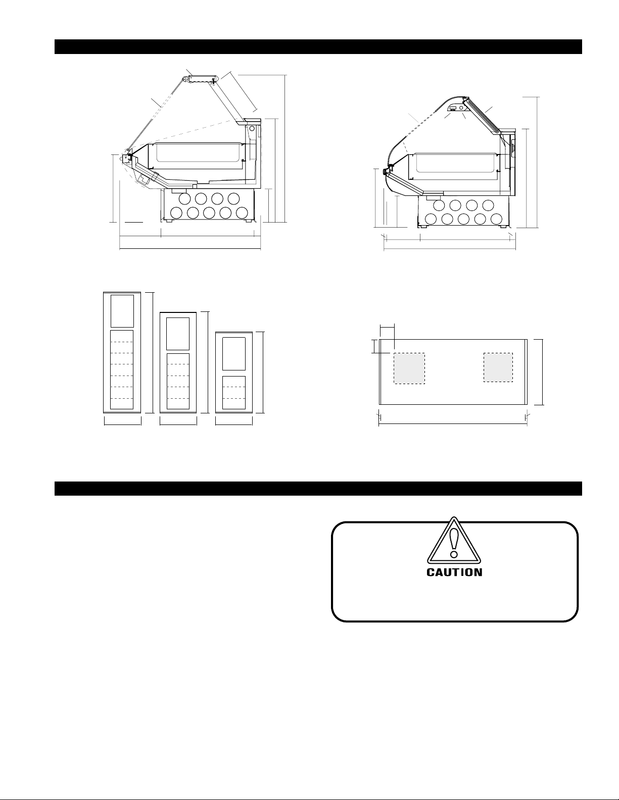
Self-Service Case Front Glass
Opening 281/2" Surface Warmer
replaces Hot Well NOTE: Non-
Glare Glass Coating on Service
Case Only
3
Cut & Plan Views
Glass
3
Top
8
/4"
15"
opening
11
5
/16"
"
2
/
1
Hot Well
"
8
/
20
3
2
5
13
/8"
15
/16"
30
3
46
/4"
8
4
"
4
/
1
34
"
8
/
1
11
/16"
ESHS
Service Hot
Self-Service Case Front
Glass Opening 28
Surface Warmer
Replaces Hot Well
"
8
/
"
7
8
/
7
20
10
7
/8"
3
11
/8"
1
/2"
Light
Food
Warmer
27"
Hot Well
1
30
11
43
/16"
ESH (-SS)
Hot Foods
/4"
Polycarbonate
Doors
21/16"
"
16
/
1
45
"
34
GRIDDLE
WARMING
WELLS
Variable
3
46
/4"
COMBO CASES
46 3/4"
Plan View
Variable
46
Variable
3
/4"
Installation
UNCRA TING THE ST AND
Place the fixture as close to its permanent position as
possible. Remove the top of the crate. Detach the walls
from each other and remove from the skid. Unbolt the
case from the skid. The fixture can now be lifted off the
crate skid. Lift only at base of stand!
EXTERIOR LOADING
These models have not been structurally designed to sup-
port excessive external loading. Do not walk on their
tops; This could cause serious personal injury and damage to the fixture.
SETTING AND JOINING
The sectional construction of these models enable them
to be joined in line to give the effect of one continuous
display. A joint trim kit is supplied with each joint.
8"
8"
DRAIN*
&
WATER*
STUB UP
19" X 19"
CASE FRONT
1" 1"
(VARIABLE LENGTHS)
Plan View
* WATER & DRAIN ON
HOT SERVICE CASE ONLY
ELEC.
MECH.
STUB UP
19" X 19"
11
"
16
/
43
Before Rasing the Glass retighten all
screws along clamshell!
3
Page 4
It is the contractor's responsibility to install
case(s) according to local construction and
health codes.
Installation cont.
LEVELING
IMPOR TANT! IT IS IMPERA TIVE THA T CASES
BE LEVELED FROM FRONT TO BACK AND
SIDE TO SIDE PRIOR TO JOINING. A LEVEL
CASE IS NECESSARY TO INSURE PROPER
OPERATION, WATER DRAINAGE, GLASS
ALIGNMENT, AND OPERATION OF THE
HINGES SUPPORTING THE GLASS.
LEVELING THE CASE CORRECTLY WILL
SOLVE MOST HINGE OPERATION
PROBLEMS.
NOTE: A. To avoid removing concrete flooring, begin
lineupleveling from the highest point of the
store floor.
B. When wedges are involved in a lineup, set them
first.
C. If there is a problem with the hinge operation,
first check if case is level. The mini top hardware
may have become loosened during shipping
(ESHS Only). If it does not look level, call
Hussmann Chino immediately for the shim kit
needed to level the mini top hardware, and
continue with the following instructions. (If
problem still persists, see "Clamshell Screw
Adjustment" section – ESH only).
All cases were leveled and joined prior to shipment to
insure the closest possible fit when cases are joined in the
field. When joining, use a carpenters level and shim legs
accordingly. Case must be raised correctly, under legs
where support is best, to prevent damage to case.
LEVELING/JOINING INSTRUCTIONS
1 . Check level of floor wher e cases are to be set.
Determine the highest point of the floor; cases will
be set off this point.
2 . Set first case, and adjust legs over the highest part of
the floor so that case is level. Prevent damage – case
must be raised under leg or by use of 2x6 or 2x4 leg
brace. Remove side and back leg braces after case is
set.
3 . Set second case as close as possible to the first case,
and level case to the first using the instructions in
step one.
4 . Apply masking tape 1/8" in from end of case on
inside and outside rear mullion on both cases to be
joined.
5 . Apply liberal bead of case joint sealant (butyl) to
dotted area shown in (Fig.2,#1) of first case. Apply
heavy amount to cov er entire shaded area.
DO NOT USE PERMA GUM!
IGHT-ESH/ESHS-0010
6. Slide second case up to first case snugly . Then lev el
second case to the first case so glass front, bumper
and top are flush.
7 . To compress buytl at joint, use tw o Jurgenson wood
clamps. Mak e sure case is level fr om front to back
and side to side on inside bulkheads at joint.
8 . Attach sections together via a 2 bolts located in the
base of the case. Secure the ov erhead structure by
bolting the bracket, located inside behind lights.
Do not use cam locks
to pull cases together!
9. Apply bead of buytl to top of bulkheads and slip on
stainless steel bulkhead cap. Also apply buytl to
seam between overhead light tubes.
10.VERY IMPOR TANT! Apply liberal amounts of
black buytl to area under interior low er legs and fill
all voids down to bulkhead.
11.Use finger to smooth buytl as thin as possible at
masking tape on inside and outside of rear mullion
(apply additional buytl if necessary). Remov e tape
applied on line #3.
CORNER WEDGES
Corner wedges are attached via fr ont and rear camlocks.
Use a 7mm allen wrench to turn the locks. Do not overtighten! Join the top by using a joint bracket (included in
joint kit) with 3/8" bolts.
COMMON END BETWEEN UNLIKE CASES AND HO T
CASES
Bolt end onto case using bolts provided in predrilled
holes behind front panel through brack et provided,
and in the rear behind the rear access panel on the
bottom. Hot case are only bolted in two places.
4
Page 5
Rev. 0010
Installation cont.
FINISHING TOUCHES
(PERFORM AFTER PLUMBING AND ELECTRICAL)
ACCESS PANELS
All electrical and drain access panels are clearly labeled
on the deck of the stand. .
INSTALLING SPLASHGUARD
After merchandisers ha ve been leveled and joined and all
electrical and plumbing work has been completed, install
the splashguards. After adjusting brackets flush with the
floor, position splashguard up behind the front panel
first—then position the lower portion over the pr eviously
adjusted brackets. Splashguar ds may be sealed to the floor
using a vinyl cove base trim. The size of trim needed will
depend on how much the floor is out of level.
NOTE: The splashguard must be removable to access compo-
nents behind it.
1. Remove all dirt and wax (etc.) from the area of the
splashguard to ensure a secur e adhesion.
2. Apply a good contact cement to the trim, allowing
for proper dry-time.
3. Install trim to the splashguard so that it is flush with
floor.
Do not seal trim to floor!
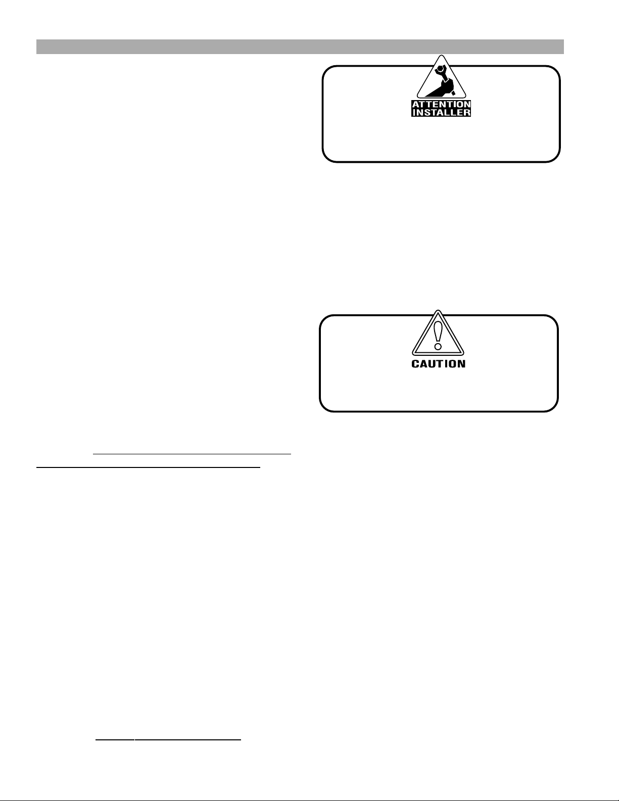
BOLT AND SEALANT LOCATIONS
WATER SUPPLY CONNECTION
The well fill water hose on these models will need to be
connected to a water supply. The water connection is 1/
2", and consists of a hand gate valve. If the water pr essure
exceeds 45 psi, a water pressure regulating valve should
be installed in the supply line, and set at 30-35 psi outlet
pressure. The pressure regulating valv e is not supplied by
Hussmann.
For a quick preheat time, the customer may want to
pipe in hot water. If hot water is piped into the case, temperature of water supply must not exceed 150°F(66°C).
In areas where water contains a hea vy mineral content, it
may be a good idea to install a cartridge-type water filtration system.
Proper water depth is 1". These cases come equipped
with an auto-fill system designed to slowly feed in water
to maintain the proper water level, and prevent damage
incurred when cold water is fed too fast into a hot well.
In common well configurations, the water level is regulated by adjusting the probe on the inside of the well. In
multi-well configurations, use the sliding plate at the rear
of the case to adjust the float level. The water lev el is maintained in direct relation to the vertical position of the
plate. The water feeds in slowly, so it is not necessary to
shut water off during cleaning. It is advisable to allow a
number of hours for the system to refill. If necessary, the
case may also be filled manually, with the use of buckets.
NOTE: Some local codes may require the installation of check
valves in the water supply.
APPLY SEALANT
JOINT BACKER
LOCATION CAMLOCK
CAMLOCK
LOCA TION
(BOLT BRACKET
IN WEDGES)
TO SHADED AREA
BOLT INSIDE
WEDGES
SEALAROUND PIPING
ACCESS HOLES
CAMLOCK
&
SEALANT
LOC ATIONS
LOCATIONS
Plumbing
WASTE OUTLET
The waste outlet is located under the hot wells and can
be accessed from the back.
Drain is 1" copper. A stub is provided for extending to
sink. Drain must be run in a material that will withstand a
150°F (66°C) (or more) temperature, such as copper.
Do not plumb below the sliding plate
on the side of the hot well!
Doing so may interfere with the
ability to adjust the water within the well!
Damage may occur if cold water is fed
into a preheated hot well too quickly!
5
Page 6
IGHT-ESH/ESHS-0010
Electrical
BEFORE SERVICING
Always Disconnect Electrical
Power at the Main Disconnect
when servicing or replacing any
electrical component.
This includes (but not limited to) Fans, Heaters,
Thermostats, and Lights.
WIRING COLOR CODE
L1 BLACK
L2 ORANGE
L3 BLUE
NEUTRAL WHITE
NOTE: High Leg Connection
Orange Only
CASE MUST BE GROUNDED
Replacing Tubular Heating Units
Undo wire clamps. Bend suppor ting clips out of the way
and remove rod.
Replacing Fluorescent Bulbs
Overhead Fluorescent lamps ar e designed to last through
many hours of use. Should there be a need to r eplace one,
it is as simple as replacing a standard fluorescent light bulb .
Tubular Heating Units
are EXTREMELY HOT!
Never touch until the case has
had ample time to cool down!
1. Turn light switch to OFF before replacing an y lighting
components.
2. Remove lamp by gently twisting / r otating it in a
froward or backwar d motion until the bulb slides
out of the track.
3. Insert new lamp by feeding the prongs into the track,
and twisitng it until you feel a "click" meaning that
the lamp is set.
6 . Turn switch on.
ELECTRICAL CIRCUIT IDENTIFICATION
Standard lighting for all models will be full length fluorescent lamps located within the case at the top.
The switch controlling the lights, the plug provided for
digital scale, and the thermometer ar e located at the r ear
of the case mullion.
ELECTRICAL SERVICE RECEPTACLES
(WHEN APPLICABLE)
The receptacles located on the exterior of the merchandiser are intended for scales and lighted displa ys. They
are not intended nor suitable for large motors or other
external appliances.
FIELD WIRING & SERIAL PLATE AMPERAGE
Field Wiring must be sized for component amperes
printed on the serial plate. Actual amper e draw ma y be
less than specified. Most component amperes ar e listed
in the “Case Specs” section, but always check the serial plate.
BALLAST LOCATION
Ballasts are located within the access panel that runs
the length of the rear of the case. Refer to diagram on
page 6.
User Information
FOOD HANDLING and HOT FOOD EQUIPMENT
These hot tables are for short-term holding and display of
precooked hot foods. They are not intended to cool or
reheat food. The temperature of the food should be
approximately 160°F when first put into the hot table.
These hot tables are best suited when used in a cafeteria
type application where the food is held and served rapidly ,
within a few hours. Any attempt to use the hot table to
display large amounts of food for long periods of time will
result in dehydrated, overcooked and unsafe food. The
quality of food will progressively worsen as the length of
time increases.
The deterioration of product quality is a function of time
and temperature. All products are affected even though
in a gravy or other liquid. They may appear to withstand
the temperature better than “dry” foods such as fried
chicken but this is not necessarily true. ALL foods will
continue to be affected by prolonged exposur e to elevated
temperatures.
The following guidelines are provided only as a general
6
Page 7

Rev. 0010
guide for the use of this equipment. The local health agency
for your area can provide specific temperature
requirements.
Critical attention must be given to the heat controls for
these hot tables. Both the upper and lower heat controls
must be adjusted to achieve proper food temperatures.
Hot foods should be held at a minimum temperature of at
least 140°F (60°C) according to 1995 FDA Food Code.
However, increasing the temperature too high will also
cause the food to over cook, dry out, lose its fla vor , texture
and color. Food held for prolonged periods at high
temperatures will also lose some of their nutritional value.
Different foods will r equire different contr ol settings. The
type of food, the quantities of f ood and length of time that
it is to remain in the hot table must be considered when
establishing control settings. Therefore, it must be the
user’ s responsibility to establish the correct contr ol settings
to maintain the food at the safest, tastiest and most saleable
condition.
Food temperatures can be accurately determined only through the use of food thermometers!
IMPORTANT OPERATION TIPS:
* Preheat case 30 minutes before loading product
using higher settings. Self Ser vice griddle type
merchandiser using Granite tiles require a longer
preheat period.
* Never place food directly into warmer. Always use
an inset and pan.
* Never pour water into a dry preheated warmer.
This may damage the unit. Always pour water into
warmer BEFORE preheating.
* Always use water in case wells, as it provides even
heat and humidity .
* Too much water or too much heat will cause
excessive condensation on the front glass,
decreasing visibility .
* Make sure all pans are in the w ell units no matter the
configuration.
Using thermometer, check product before
*
loading in case (150°-160°).
* Always use warmer in wet operation when warming
thick food items.
* Stir thick foods such as chili, fudge and chowders
often to keep foods uniformly heated and prevent
scorching.
* At start, set wells to "7", and overhead heat to "5".
After loading, recheck temperature every 1/2 hour
to see that unit is operating properly. Adjust the
thermostat (a higher number for hotter and a low er
number for cooler) to maintain product
+
temperature of 140°F
(60°C.) minimum. The setting
will depend on the type of product being displa y ed
and how much there is in the well. Be sure to test
product temperature with a thermometer
frequently for good pr oduct maintenance.
* Keep cov er(s) on insets to maintain food quality and
temperature.
* Food must always be placed into a displa y pan ov er
the well, ne ver directly into the w ell.
* Food should not be stacked above the top of the pan.
Food above the top of the pan will dry out rapidly .
* Food juice or gravy should be stirr ed frequently and
any meats should be basted with the gravy. Stir and
rotate foods as needed. Wipe up spills immediately
- for eye a ppeal now, and easier cleaning later .
* Food should be rotated periodically from the
bottom to top.
* If practical, the food should be cov ered during slow
sale periods to reduce dehydration.
* At end of the day , r emove product and let case cool.
Then clean with soap and water (use oven cleaner
on the difficult spots). Polish and clean glass with a
good glass cleaner .
All griddle type units are designed to maintain
termperatures above the FDA guideline of 140°F. This is
product temperature, not air or griddle temperatur e. Due
to the open design of these units, they must be loaded
with product for pr oper operation. When units are empty ,
they experience rapid rise of heated air from air outside
the case. This action gives empty units a false, lower than
desired, temperature reading. Loading the case traps the
air at the griddle, raising temperatures to the 165°F to
185°F range, keeping product well above the FDA
guidelines. Remember, these units must be loaded with
product to maintain safe product temperature.*
Food must be displayed in a single layer in direct contact
with the griddle at all times.
CONTROLS
The controls to regulate the temperature of the well
heaters, griddle, and the overhead heat ar e located at the
rear of the case.
OVERHEAD HEATING SYSTEM
Tubular heating units are located above each well to
provide top heat. To obtain the proper food temperatures, the well heaters, griddles, and heat lamps must be
adjusted. Maximum limits should be avoided to prevent
overcooking or drying out food.
WELL HEATING SYSTEM
The heating well is thermostatically controlled with an
indicator light showing when the heater has cycled on and
7
Page 8
is heating. The pilot lamp beside the control knob indi-
OVERHEAD HEAT LEFT
LO HI
6
543
2
OFF
OVERHEAD HEAT LEFT
LO HI
6
543
2
OFF
430-01-0365 9810
1
2
3
4567
8
9
10
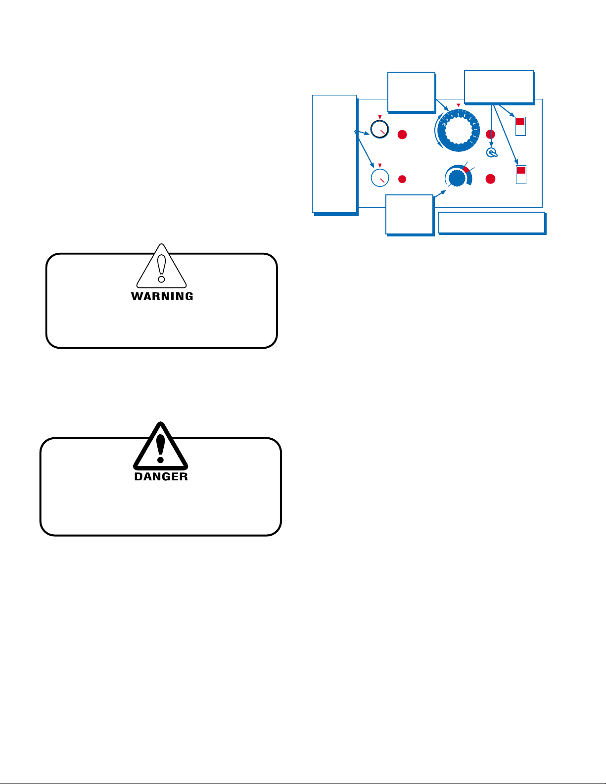
START-UP
(Control Panel on Rear of Case)
POWER
LIGHTS
DECREASE
INCREASE
WATER
FILL
O/H HEAT
LIGHT
TO/H HEA
LIGHT
Check to make sure all lights come
on at start-up. If they do not, contact
your Service Department.
HOT WELL
TEMP.
INITIAL
SETTING
"7"
TURN POWER,
LIGHTS AND
WATERFILL ON
FIRST
OVERHEAD
HEAT
INITIAL
SETTING
"5"
Depending
upon the length
of the case,
there may be
more than one
(1) group of
overhead heat
switches.
However, they
should all be
set at the same
setting.
GRIDDLE
TEMP.
INITIAL
SETTING
"7"
cates when the well heater is heating.
AUTO-FILL OPERATION
fill system that allows automatic filling of the heating pans.
The water level is pr eset and automatically regulated. The
proper water level is 1 inch.
START-UP
Hussmann hot cases are equipped with an internal auto
1. Close drain valve.
2 . Turn all black toggle switches (Water, Fill, Lights) on.
The well will begin to fill appro ximately 15 seconds
after the switch is turned on. Fill to 1" depth.
Damage may occur if cold water is fed
into a preheated hot well too quickly!
3. T urn all overhead heat to the "5" position.
4. After the w ell has begun to fill, turn the w ell heater
and griddle dial to the "7" position.
Do not turn on the well heater
if there is no water in the unit
or damage will occur!
5. Place empty pans in the case to help the case pr eheat
faster . The unit will take appr oximately 45 minutes to
preheat. It is also impor tant that the small pan
divider bars are installed properly betw een each pan.
These dividers provide a seal ar ound each individual
pan and are necessary to maintain the proper
temperature of the food products. Extra dividers
should be stored outside of the case.
IGHT-ESH/ESHS-0010
SHUTDOWN
1. Remove all usable food.
2. T urn off all heat and light controls.
3. T urn well heater contr ol to off.
4. Open water drain to drain water from the well. In its
open position, the valve handle will point in the same
direction as the drain pipe.
5. Thoroughly clean all stainless steel surfaces by
washing them down with a mild soapy solution with
a bacteria killing agent. NOTE: When cleaning hot
well area, pay special attention to the auto-fill sensor .
It should be kept clean or the water in the w ell could
possibly fill to capacity and overflow. Clean
occasionally with a mild cleaning solution. Wiping it
dry will help ensure that the sensor operates
properly.
6. Wipe down non-glass areas on the outside of the
case.
CASE CLEANING
Long life and satisfactory performance of any equipment
are dependent upon the care given to it. To insure long
life, proper sanitation and minimum maintenance costs,
the fixture should be thoroughly cleaned frequently. The
interior bottom may be cleaned with any domestic soap
or detergent based cleaners. Sanitizing solutions will not
harm the interior bottom, how ever , these solutions should
always be used accor ding to the manufacturer’ s directions.
It is essential to establish and regulate cleaning procedur es.
This will minimize bacteria causing discoloration which
leads to degraded product appearance and significantly
shortening product shelf life.
Soap and hot water are not enough to kill this bacteria. A
sanitizing solution must be included with each cleaning process to eliminate this bacteria.
8
Page 9
Rev. 0010
User Information cont.
1. Scrub thoroughly , cleaning all surfaces, with soap and
hot water .
2. Rinse with hot water, but do not flood.
3. Apply the sanitizing solution according to the
manufacturer’ s dir ections.
4. Rinse thoroughly.
5. Dry completely before resuming operation.
CLEANING GLASS & MIRRORS
Only use a soft cloth and mild glass cleaner for cleaning
any glass or mirrored components. Be sure to rinse
and/or dry completely.
NON-GLARE GLASS
The high optical clarity of this glass is possible due to
special coatings on the glass surface itself. To preserve
this coating and the optical clarity, keep the glass clean.
®
Windex
or Glass Plus® are the only solutions recommended to be used to clean the non-glare glass. The
damage to the glass from improper, caustic solutions is
irreparable.
to the surface. Incorrect cleaning agents or cleaning cloths
can cause micro scratching of the surface, causing the plastic
to haze over time.
CLEANING
Hussmann recommends using a clean damp chamois, , or a
paper towel marked as dust and abrasive free with 210
Plastic Cleaner and Polish available by calling Sumner
Labs at 1-800-542-8656. Hard, rough cloths or paper
towels will scratch the acrylic and should not be used.
ANTISTATIC COATINGS
The 210® has proven to be v ery effective in not only cleaning and polishing the Plexiglass surface, but also providing
anti-static and anti-fog capabilities. This pr oduct also seals
pores and provides a protective coating.
• DO NOT USE ABRASIVES OR STEEL WOOL SCOURING PADS
(these will mar the finish)
®
In addition to cleaning the glass with the recommended
product, there are precautions that should be taken when
working and cleaning the inside of the case.
• When cleaning the inside of the cases, we
recommend that the glass be fully opened and
covered to prevent solutions from splashing onto
the glass and ruining the coating on the inside.
CLEANING PRECAUTIONS
WHEN CLEANING:
Never Use a Cleaning or Sanitizing Solution
that has an OIL BASE (these will dissolve the
butyl sealants) or AMMONIA BASE
(this will corrode the copper components
of the case)
TO PRESERVE THE ATTRACTIVE FINISH:
Do Use Water and a Mild Detergent for
the Exterior Only!
Do Not Use Abrasives or Steel Wool Scouring Pads
(these will mar the finish)
PLEXIGLASS & ACRYLIC CARE
Improper cleaning not only accelerates the cleaning cycle
but also degrades the quality of this surface. Normal dail y
buffing motions can generated static cling attracting dust
9
Page 10
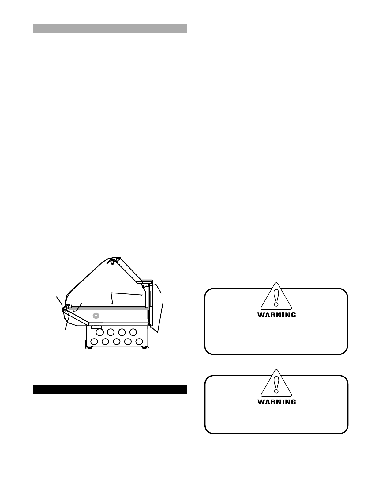
Lift-up Glass
IMPORTANT!
READ BEFORE RAISING FRONT GLASS :
The top cylinders, which allow the raising and lo wering
of the glass, have been carefully tested for proper tension. However, during shipment, the clamshell screws
can work themselves out and/or the lubricant inside ma y
have settled. This settling may cause excessive or uneven
tension on the glass - to the point of breakage.
Before Rasing the Glass retighten all
screws along clamshell!
After installing new cylinders, it is advisable to perf orm
these three easy steps before completely raising the fr ont
glass.
1 . Slowly raise and low er each glass section 6 times, to
a height of 6".
2 . Increase the height to 12", and raise and lower the
glass 6 more times.
3. Finally , raise the glass to it's full extension. This
should release any settled lubricant in the cylinders,
and prevent an y stress on the front glass. (1)(3)
ESH Curved Glass
Replacement
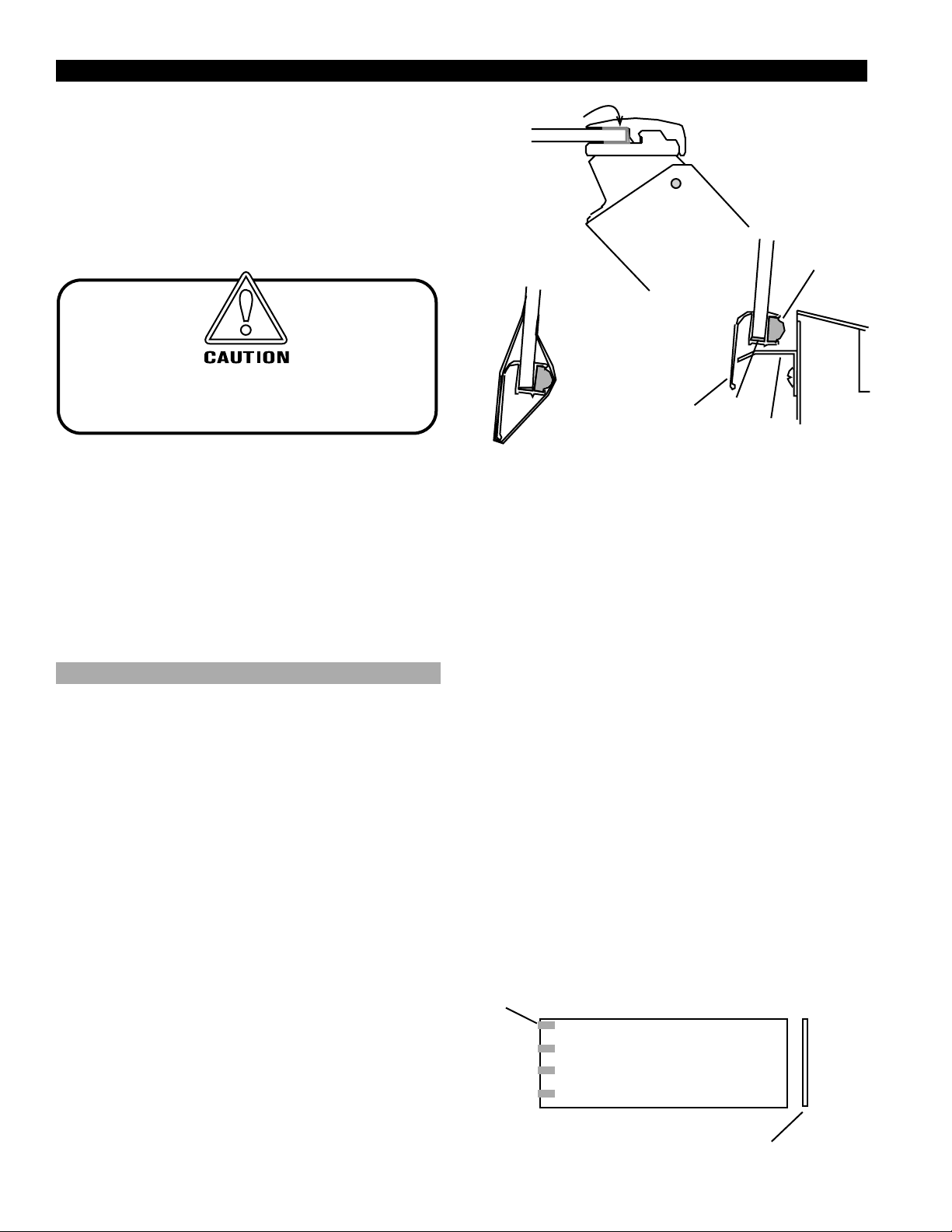
BROKEN GLASS REMOVAL
1. Loosen set screws along clamp .
2. Remove plastic PVC channel (1) betw een clamshell
and glass.
3. Use new plastic PVC channel. Lift off top of
clamshell, and clean off any particles. Replace
clamshell (Do Not Tighten).
NEW GLASS PREP
1. Centering rubber gasket (2) on handrail, slide all
but outer 3" of gasket into handrail.
2 . Apply 3/8" bead of buytl to outer 2" of handrail,
and insert remaining gasket. Trim to length of
handrail.
3 . Apply 3/8" bead of buytl to bottom of glass receiv er
(3) on handrail.
4 . Center handrail on glass. Firmly push onto bottom
edge of glass.
5 . Tape securely (4), and allow 12 hours to cur e.
NOTE: Do not tape where glass support angles are located on
case (approximately 11-13" from ends).
IGHT-ESH/ESHS-0010
CLAMSHELL ASSEMBLY
(1) PVC U-CHANNEL
(2) RUBBER SEALER
GASKET
SILICONE
(5) SUPPORT
ANGLE
(4) TAPE SECURELY
AROUND THE
WHOLE END
INSTALL GLASS
(3) HANDRAIL
1. Place PVC U-channel (1) on glass.
2. With one person holding each end of the glass, lift
up and place top of glass inside clamshell (glass will
be in fully open position.) Center glass within
clamshell.
3 . With one person holding the glass in the clamshell,
tighten the two set scre w on each end and two
equally spaced set screws in the center of the glass
to about 4 ft/lbs.
4. Open and close glass gently , checking to see that the
alignment can be corrected by r eleasing the set
screws enough to mov e the glass forward and
backward.
5. Glass should rest squarely on glass support angles
(5). If not, they can be adjusted by loosening the
screw that attaches them to the case.
6. After glass is aligned, tighten set scre ws.
7. Attach wipes to appropriate edge of glass filling gap
between adjacent pieces of glass. See “Installing
Glass Sweep” section for complete instructions.
8. Lea ve taped glass closed for 12 hours.
INSTALLING GLASS SWEEP
After installing new glass onto a case, it is important to
replace the glass sweep .
Masking Tape
Front Glass
10
Glass Sweep
Page 11
Rev. 0010
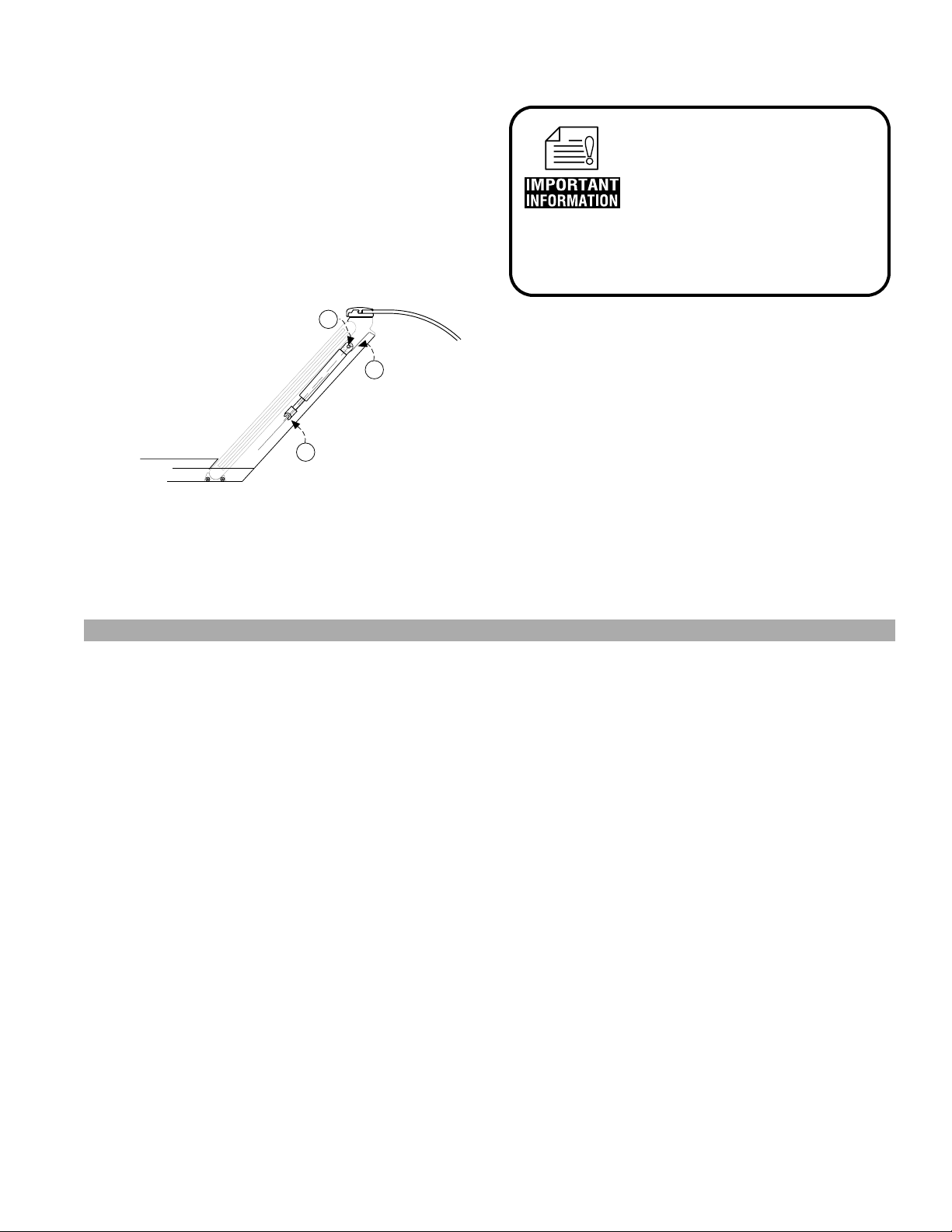
PISTON REPLACEMENT
1. OPEN GLASS. Glass must remain open throughout
procedure.
2. Loosen Allen set Scr ew (1).
3. While holding onto piston, remov e and sav e pin (2).
4. Slide piston out.
5. Slide new piston in making sur e the U-shaped end fits
around pin at bottom of arm (3).
6. Line up upper pin with arm, arm with strut, and
replace pin.
7. Replace Allen set screw .*
REAR OF CASE
M
R
A
2
N
1
O
T
S
I
P
3
FOR PROMPT SERVICE
When Contacting the Factory
regarding problems, Be sure
to have the Case MODEL and
SERIAL NUMBER Handy.
This Information is on a plate
located on the case itself.
*After installing either piston, prime them as outlined in
the "Read
Before Raising Glass" warning found in the "Installation
Instructions" section of this booklet.
ESHS Straight Glass
IF GLASS DOES NO T CLOSE/STA Y OPEN PROPERLY-
LEVEL MINI TOP HARDWARE
During shipping, it is possible that the mini top hardware
housing the pistons and armature has been jostled out of
position. This affects the opening angle of the glass.
1. Be sure mini top hardware is level front to back b y
placing a level along the top of the mini top housing
at each hinge location. If it is not, y ou will need
a shim kit before y ou can correct. Order fr om
Hussmann Chino.
2. Remove top glass and panel at top of hardware
housing.
3. Mark position of hardware (glass) in r elation to case
before loosening hex screw using masking tape
applied on mini top hardware and case, and pen. Hex
screw allows r ealignment of glass angle and position
front to back.
4. Raise glass and loosen hex screw . (See item/diagram
#6 on page 13.)
5. Shim to adjust until level using shims available from
Hussmann Chino (16 or 20 gauge stainless steel).
6. Check angle by using lev el placed on top of mini top
hardware. Note: a 6" level will fit perfectly within
access area.
1
7. Remove 1
/4" chrome cap at front of case arm
support. The r emoval of this cap allows finger access
to hold nut plate while tightening hex screw .
8. Hold nut plate and tighten hex screw.
9. If there is still a problem with glass sta ying open over level by adding an ad dition shim under front of case.
NOTE: BEFORE MAKING ANY OF THE
11
Page 12
RECOMMENDED ADJUSTMENTS,
VERIFY THAT THE CASE(S) HAVE BEEN LEVELED PROPERLY.TIPS & TROUBLESHOOTING
Before calling for service if something seems wrong, check the following:
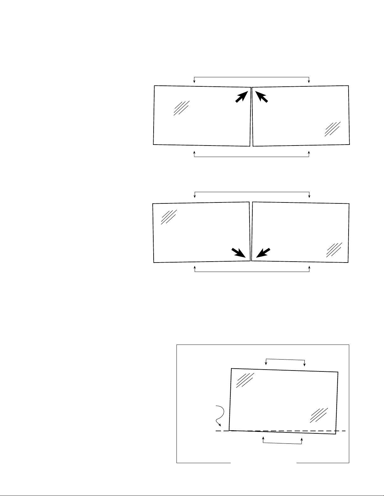
1. INSPECT THE GAP BETWEEN THE GLASS PANELS
A. If pinched at the top:
Back or Top edges of glass
Gap is more narro w at the top than at the bottom.
Then see Item 4 / Uneven Gap .
Front or Bottom edges of glass
B. If pinched at the bottom:
Gap is more narr ow at the bottom than at the top.
Then see Item 4 / Uneven Gap
Back or Top edges of glass (hinge side)
IGHT-ESH/ESHS-0010
C. If gap is even, but too narrow or too wide and conditions ar e satisfactory then:
Front or Bottom edges of glass
Item 6 / Front and Back Adjustment..
T ypical ga p = 3/16" to 1/4"
2. CHECK CLOSING ACTION OF THE GLASS PANEL
Test each panel by gently pushing it to close. Does the glass panel bounce or wobble as it closes?
A glass panel that does not close smoothly and neatly ,
most likely is misaligned with the front edge of the
glass and the surface or edge which it closes upon.
Refer to diagram at the right.
Rubber gasket or
(surface that glass
closes upon)
To correct problem
Go to Item 5.
Back
edge of glass (hinge side)
Front
edge of glass or grip rail (ESCS)
12
View: Top looking down
Page 13
Rev. 0010
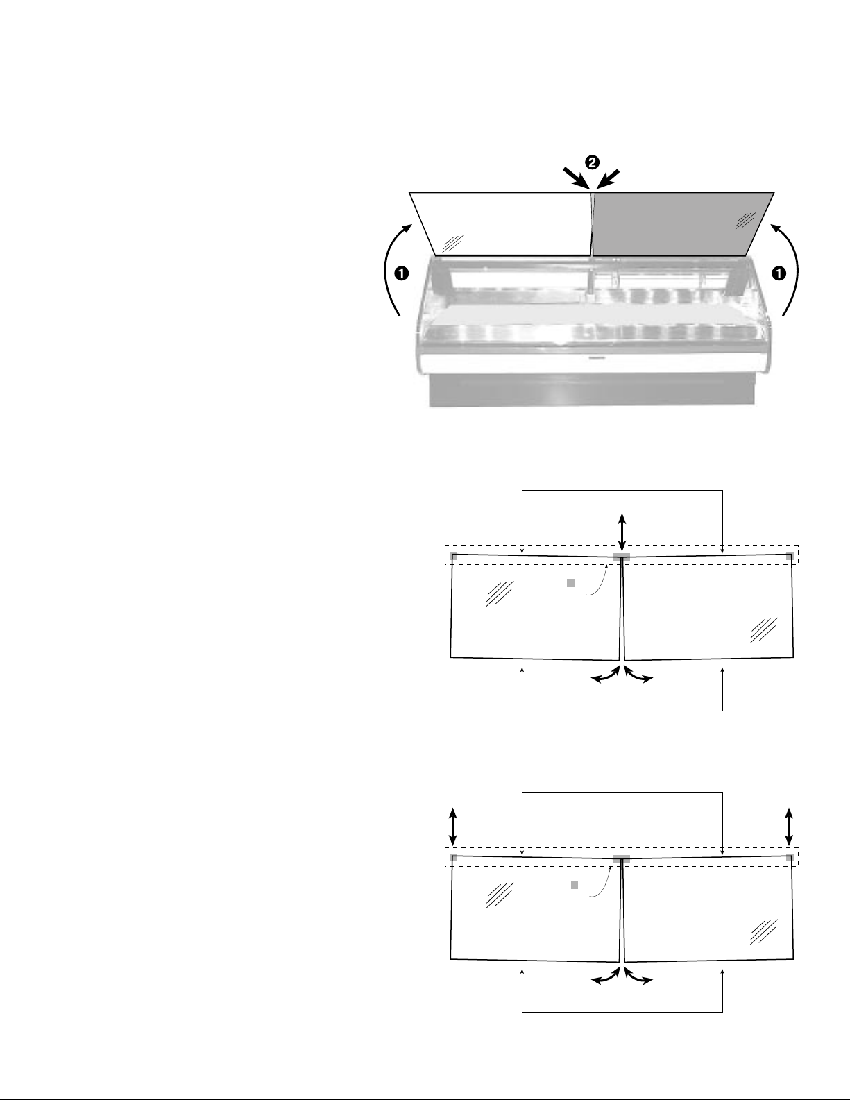
3. CHECK OPENING ACTION OF GLASS PANELS
A. Lift up adjacent glass panels at the same time
and note the following:
B. Do the corners of the glass maintain an ev en gap
throughout the tra vel of the panels? And do the
corners touch or overlap at any point?
To correct problem
Go to items 4 & 5.
4. STRATEGIES FOR CORRECTING UNEVEN GAP AND OPENING OVERLAP PROBLEMS
VER TICALL Y adjust the hinge(s) to ev en the gap
A. Adjust center hinge (Outer hinges
Top edges of glass (hinge side)
stationary)
As this diagram indicates, raising the middle
hinge draws the bottom edges closer together.
Whereas lowering the hinge widens the gap .
Hinge
Hardware
B. Adjust outside hinges (Center hinge
stationary)
This diagram indicates that raising the outside
hinges widens the gap at the bottom; wher eas,
Bottom edges of glass
lowering the outside hinges will dra w the
bottom edges closer together .
Top edges of glass (hinge side)
Which hinge(s) should I adjust first?
In most cases the center hinge is the first candidate,
but if it cannot be adusted because, either the
adjusment screw is max ed out or no additional shims
can be added or removed, then obviously the outer
hinges must be adjusted
For RGSMS/RGSD…/FS cases go to Item 5 /
Correcting Glass Bounce.
13
Hinge
Hardware
Bottom edges of glass
Page 14

5. STRATEGIES FOR CORRECTING GLASS BOUNCE
AND OPENING OVERLAP PROBLEMS
ADJUST HINGES FRONT – BACK.
A. Adjust center Hinge (Outer hinges
stationary)
As this diagram indicates, pulling the
middle hinge further back, pulls the inside
edges closer to the surface or edge which
the glass rests upon. And pushing the
middle hinge to the front, pushes the
inside edges further away fr om the
surface or edge which the glass rests
upon.
IGHT-ESH/ESHS-0010
B. Adjust outside hinges (Center hinge
stationary)
As this diagram indicates, pulling the
outside hinge further back, pulls the
outside edge closer to the surface or edge
which the glass rests upon. And pushing
the middle hinge to the front, pushes the
inside edges further away fr om the
surface or edge which the glass rests
upon.
Which hinge(s) should I adjust first?
In most cases the center hinge is the first candidate, but if the arm/mini-cam is at its maximum or minimum position,
then obviously the outer hinges must be used.
14
Page 15
Rev. 0010
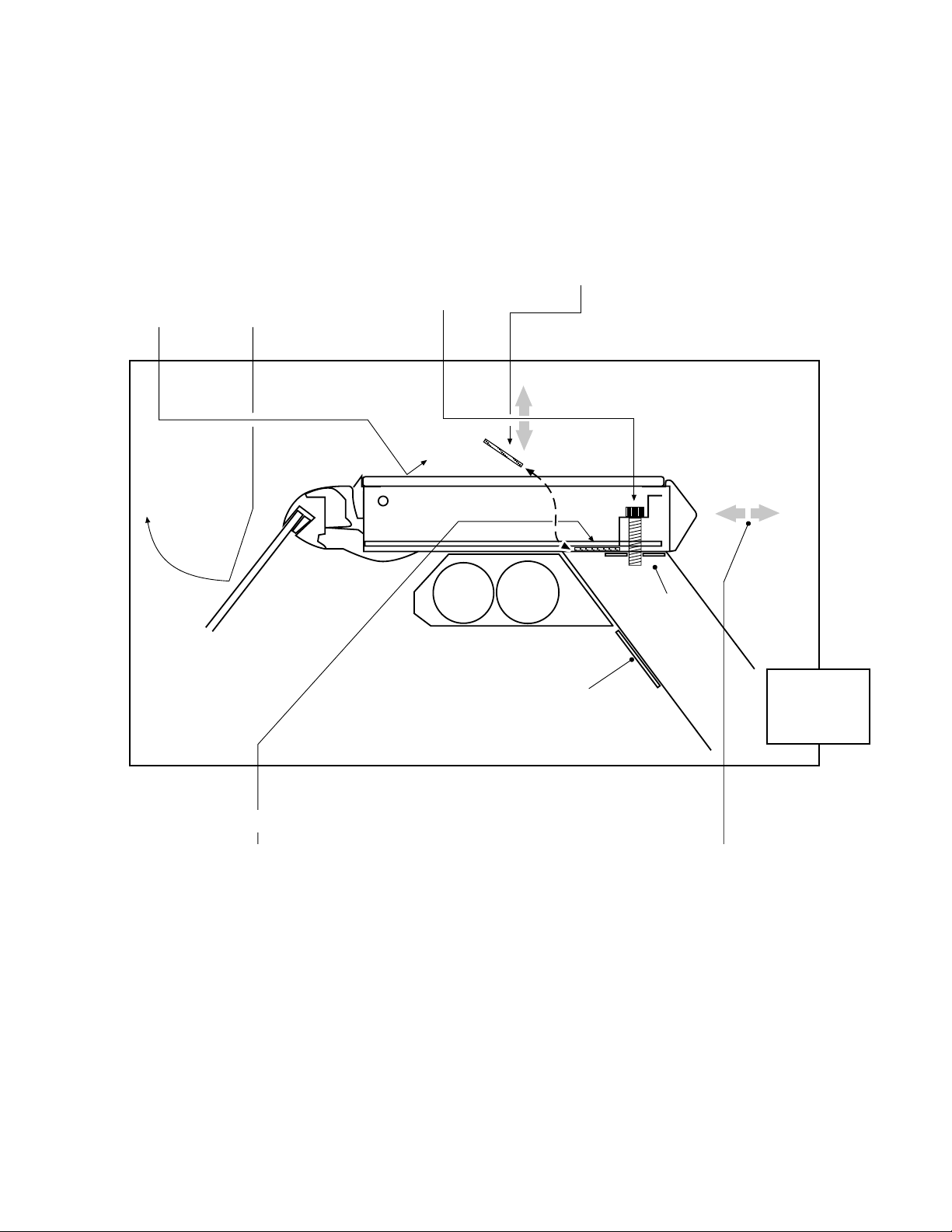
6. VERTICAL AND FRONT TO BACK ADJUSTMENT
AND OPENING OVERLAP PROBLEMS
• VERTICAL ADJUSTMENT
1. Remove 2. Lift open 3. Loosen hex screw 4. Add or remove 5. Close glass panel(s)
top glass glass panel(s) (1/4" allen). shims as needed. and check alignment
and panel and relieve Remove chrome (see note on shims Retighten hex screw
enclosing tension on access plate in order below) and reinstall removed
mini-top hinge. to hold nut plate. components.
hardware.
Inside
of Case
nut
plate
Chrome cap
for access to
nut plate
Back
of Case
CUT VIEW:
Mini Top
Hardware
• FRONT– BACK ADJUSTMENT
1. Remove 2. Estimate 3. Lift open 4. Loosen hex screw 5. Slide the mini-top
top glass amount of glass panel(s) (1/4" allen) slightly. forward or backward
and panel adjustment and relieve Remove chrome to the mark in step 2.
enclosing and make tension on access plate in order Check alignment of
mini-top pencil mark hinge. to hold nut plate. glass.
hardware. on the Retighten components.
NOTE: Standard shim thickness is 1/16"
15
Page 16
TIPS & TROUBLESHOOTING
Before calling for service if something seems
wrong, check the following:
1. Check electrical power supply to the equipment for
connection.
2. Check fixture loading. Ov erstocking case will affect
its proper operation.
IGHT-ESH/ESHS-0010
FOR PROMPT SERVICE
When Contacting the Factory
regarding problems, Be sure
to have the Case MODEL and
SERIAL NUMBER Handy.
This Information is on a plate
located on the case itself.
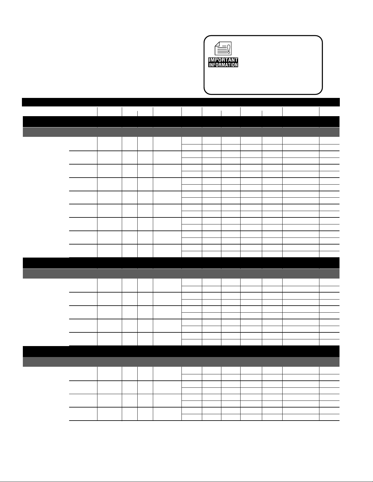
MODEL LENGTH PANS QTY. SIZE LEVELS VOLTS PHASE Loads PHASE Loads Diagram Number
SERIAL NUMBER HANDY.
WELLS GRIDDLES SHELF CIRCUIT 1 CIRCUIT 2 WIRING Remarks
Case Specifications
Common Well Service
ESH, ESHS
4' 3 208 3Ø 16 - W6000001
240 3Ø 18 - W6000001
5' 4 208 3Ø 19 - W6000002
240 3Ø 22 - W6000002
6' 5 208 3Ø 21 - W6000003
240 3Ø 25 - W6000003
7' 6 208 3Ø 21 1Ø 9 W6000004
240 3Ø 24 1Ø 10 W6000004
8' 7 208 3Ø 25 1Ø 11 W6000005
240 3Ø 28 1Ø 12 W6000005
9' 8 208 3Ø 28 1Ø 12 W6000006
240 3Ø 32 1Ø 14 W6000006
10' 9 208 3Ø 32 1Ø 13 W6000007
240 3Ø 36 1Ø 15 W6000007
11' 10 208 3Ø 35 1Ø 15 W6000008
240 3Ø 41 1Ø 17 W6000008
12' 11 208 3Ø 40 1Ø 17 W6000009
240 3Ø 45 1Ø 19 W6000009
Self Service
ESH-SS, ESHS-SS
4' 1 4' 208 1Ø 10 W6000010
240 1Ø 11 W6000010
5' 1 5' 208 1Ø 13 W6000011
240 1Ø 15 W6000011
6' 1 6' 208 1Ø 15 W6000012
240 1Ø 17 W6000012
8' 2 4' 208 1Ø 24 W6000032
240 1Ø 28 W6000032
12' 2 6' 208 3Ø 22 W6000015
240 3Ø 25 W6000015
Combination
ESH-Combo, ESHS-Combo
6' 3 1 2' 208 3Ø 19 W6000014
8' 3 1 4' 208 3Ø 23 W6000016
10' 5 1 4' 208 3Ø 18 3Ø 15 W6000017
12' 7 1 4' 208 3Ø 25 3Ø 14 W6000018
240 3Ø 22 W6000014
240 3Ø 26 W6000016
240 3Ø 20 3Ø 18 W6000017
240 3Ø 28 3Ø 16 W6000018
16
Page 17
Rev. 0010
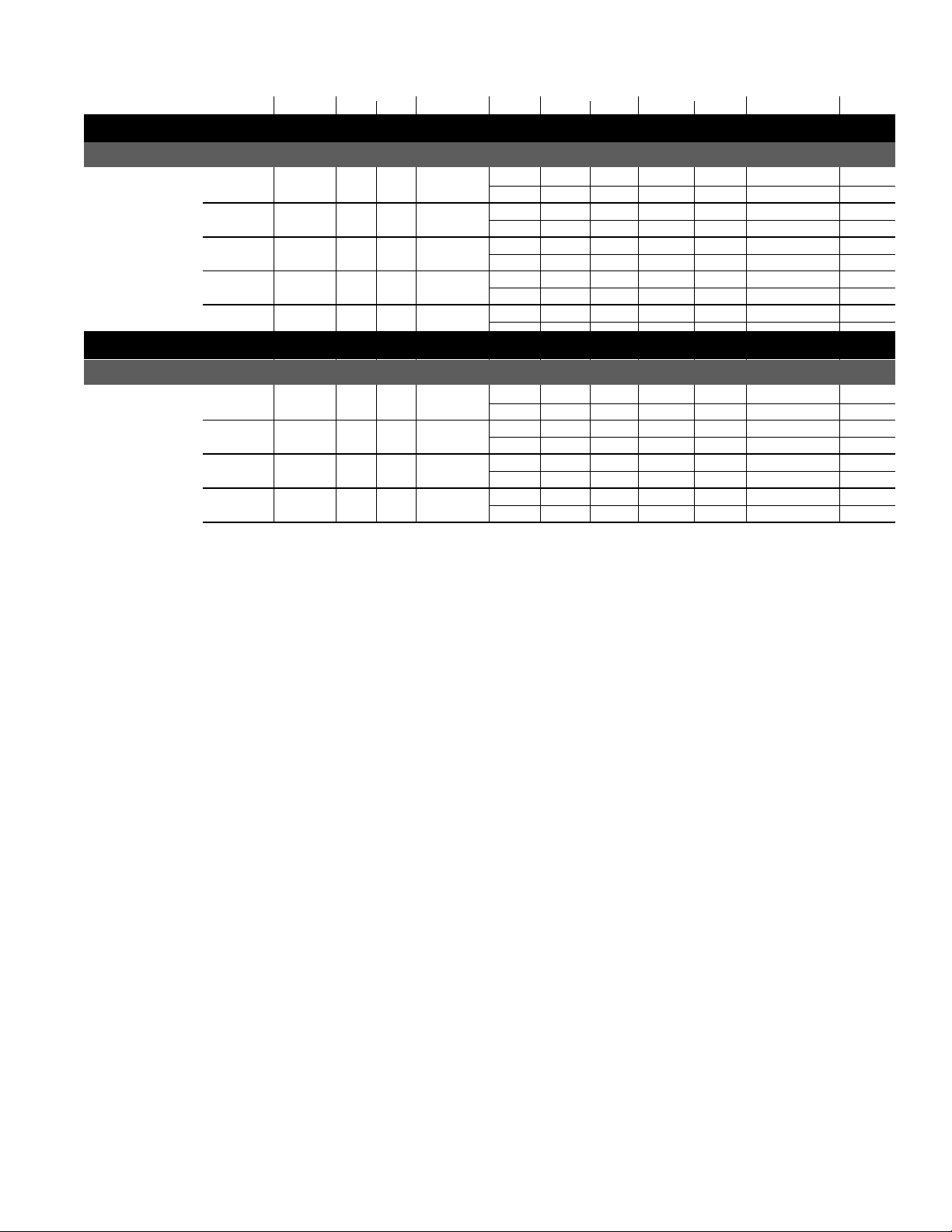
MODEL LENGTH PANS QTY. SIZE LEVELS VOLTS PHASE Loads PHASE Loads Diagram Number
WELLS GRIDDLES SHELF CIRCUIT 1 CIRCUIT 2 WIRING Remarks
Individual W ells Service
ESH, ESHS
4' 3 208 3Ø 17 W6000019
240 3Ø 19 W6000019
6' 5 208 3Ø 21 W6000021
240 3Ø 25 W6000021
8' 6 208 3Ø 30 W6000022
240 3Ø 35 W6000022
10' 8 208 3Ø 20 3Ø 20 W6000025
240 3Ø 24 3Ø 24 W6000025
12' 10 208 3Ø 23 3Ø 25 W6000027
240 3Ø 26 3Ø 27 W6000027
Combination
ESH-Combo, ESHS-Combo
6' 3 1 2' 208 3Ø 19 W6000028
240 3Ø 22 W6000028
8' 3 1 4' 208 3Ø 17 W6000029
240 3Ø 20 W6000029
10' 5 1 4' 208 3Ø 18 3Ø 13 W6000030
240 3Ø 20 3Ø 15 W6000030
12' 6 1 4' 208 3Ø 21 1Ø 20 W6000031
240 3Ø 24 1Ø 23 W6000031
17
Page 18
Sheet 1 of 1
final
BK
Boris Kasrel
Date:
Project Title:
Drawing No.:
Drawn By:
Next Assembly:
Drawing Title:
Date:
Hussmann Corporation
13770 Ramona Avenue
Chino, CA. 91710
(909)-590-4910
Lic.#: 644406
Revisions:
No. Description:
Checked By:
By:
10.21.99
Ballast
Power
#125-01-0311
LIGHTS
#125-01-0311
S
L1
L2
L3
N
G
Contactor 40A
#125-01-1001
L
Remote sensing
bulb
Level Controller
Water Solenoid
Valve
L1
G
L2
H
L
NC
C
NO
L3
L2
L1
G
S
black
orange
10 AWG
Term Block
black
white
Toggle-Well Control
(Water Level Control)
S
o
u
t
h
er
n
E
q
ui
p
m
e
n
t
12x27 Removable Pan Common Well
(3) 1200/1600~ 208/240V Htr's
Cal-Rod HE-01-46"
1400W/~240V
L
H1
L1
L2
H2
P
Overhead Installation
Optional Left
~
1
1
5
V
/
5
A
m
p'
s
~
1
1
5
V
/
5
A
m
p'
s
Optional Right
F28T5/TL830
WH3-120-164
Ballast
Level Controller
black
white
SS
white
~
2
0
8
/
2
4
0
V-
3
ø-6
0
Hz
black
10 AWG
15A
FUSE
F28T5/TL830
Water Level Sensor
T-Stat /
Infinite Control
orange
black
blue
10 AWG
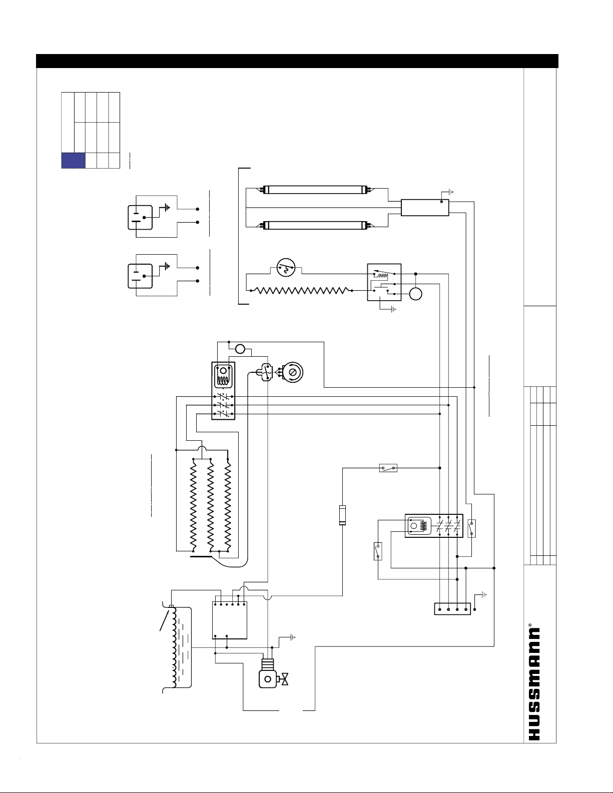
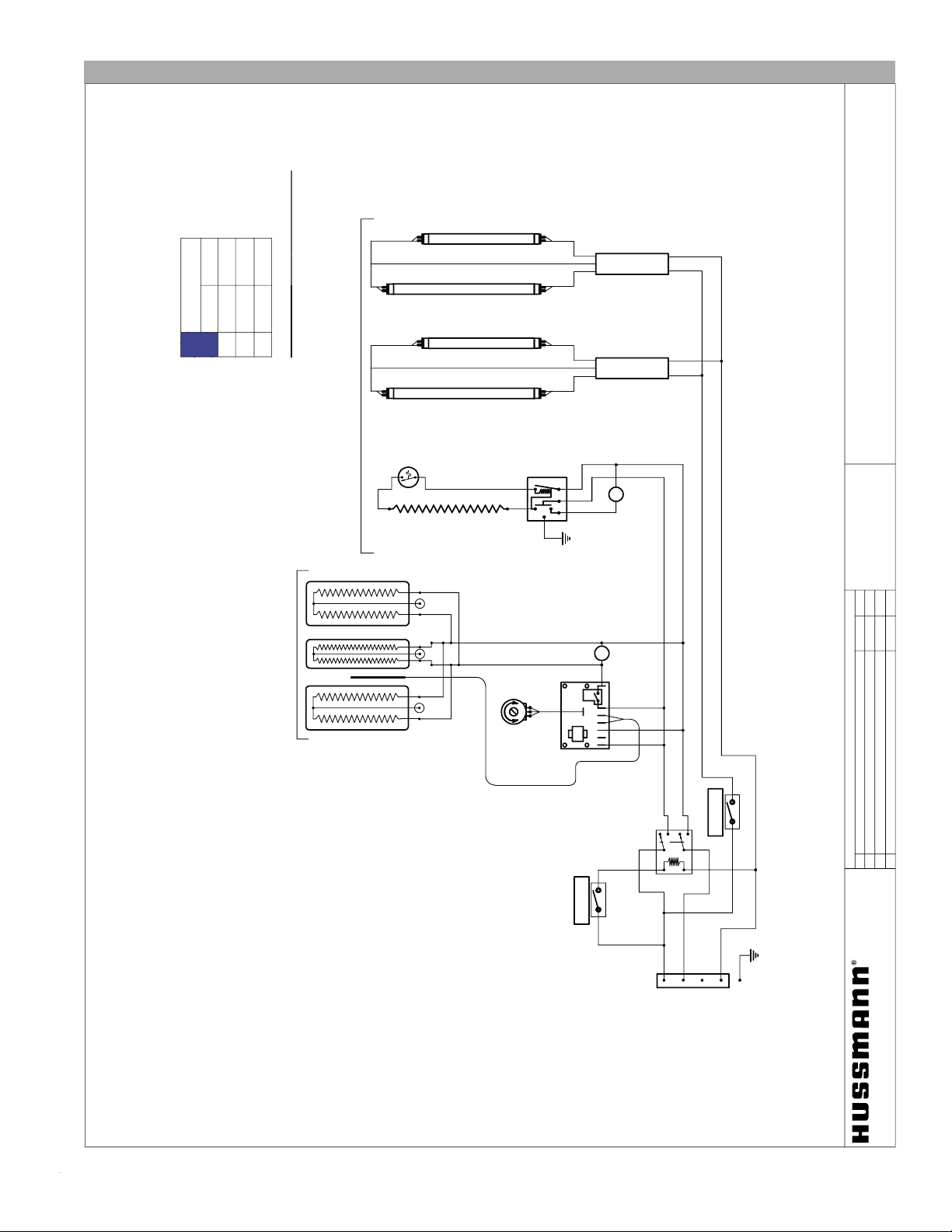
4'Lg Common Well 3 Removable Pans Wiring
W6000001
Loads, amp
~208V ~ 240V
L1
L2
L3
15.6 18.0
N
o
t
e
:
case must be grounded
15.6
18.0
ASH, ESH-S, RGSH-L/S, OSH Common Well,
Removable Pans Hot Food Service Counter
11.0
12.7
Electrical Schematics
IGHT-ESH/ESHS-0010
18
Page 19

Rev. 0010
ASH, ESH-S, RGSH-L/S, OSH
Sheet 1 of 1
final
BK
Boris Kasrel
Date:
Project Title:
Drawing No.:
Drawn By:
Next Assembly:
Drawing Title:
Date:
Hussmann Corporation
13770 Ramona Avenue
Chino, CA. 91710
(909)-590-4910
Lic.#: 644406
Revisions:
No. Description:
Checked By:
By:
10.21.99
WH2-120-135
Ballast
POWER
#125-01-0311
LIGHT
#125-01-0311
S
L1
L2
L3
N
G
Contactor 40A
#125-01-1001
S
L
Control Panel,
Thermostat Infinite
Controller
Remote sensing bulb
Water Level Switch
Level Controller
Water Solenoid
Valve
L1
G
L2
H
L
NC
C
NO
L2
G
black
~
2
0
8
/
2
4
0
V-
1
ø-6
0
Hz
S
black
orange
black
Term Block
black
white
Toggle-Well Control
(Water Level Control)
(2) Cal-Rod HE-02-34"
1050W/~240V
L
H1
L1
L2
H2
P
orange
black
white
blue
Overhead Installation
Optional Left
~
1
1
5
V
/
5
A
m
p'
s
~
1
1
5
V
/
5
A
m
p'
s
Optional Right
F21T5/TL830
S
Water Reservoir
L3
L1
black
4 Pan Common Well
(4) 1600 W /~ 240V Htr's
white
Cal-Rod HE-03-22"
1050W/~240V
F14T5/TL830
blue
10 AWG
10 AWG
10 AWG
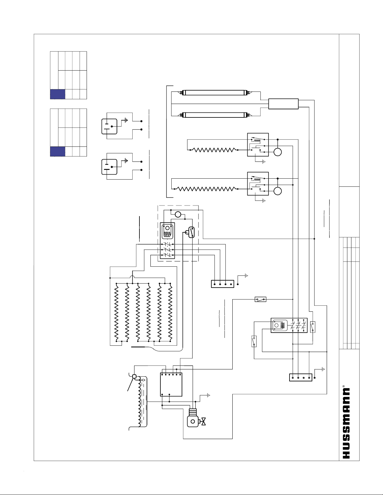
5' Common Well 5 Pan Hot Food Service Counter
W6000002
Note: case must be grounded
208 V 240 V
L1
L2
L3
14.0
16.2
Load, amps
19.0
22.0
19.3
22.3
19
Page 20

ASH, ESH-S, RGSH-L/S, OSH
Sheet 1 of 1
final
BK
Boris Kasrel
Date:
Project Title:
Drawing No.:
Drawn By:
Next Assembly:
Drawing Title:
Date:
Hussmann Corporation
13770 Ramona Avenue
Chino, CA. 91710
(909)-590-4910
Lic.#: 644406
Revisions:
No. Description:
Checked By:
By:
02.03.2000
WH3-120-164
Ballast
POWER
#125-01-0311
LIGHT
#125-01-0311
S
L1
L2
L3
N
G
Contactor 40A
#125-01-1001
S
L
Control Panel,
Thermostat,
Infinite Controller
Remote sensing bulb
Water Level Switch
Level Controller
Water Solenoid
Valve
L1
G
L2
H
L
NC
C
NO
L2
G
black
S
black
orange
10 AWG
Term Block
black
white
Toggle-Well Control
(Water Level Control)
Cal-Rod HE-05-67"
2100 W/~240V
L
H1
L1
L2
H2
P
white
Optional Left
~
1
1
5
V
/
5
A
m
p'
s
~
1
1
5
V
/
5
A
m
p'
s
Optional Right
(2) F21T5/TL830
S
L
Water Reservoir
L3
L1
black
5 Pan Common Well
(5) 1600 W /~ 240V Htr's
white
Overhead Installation
white
blue
~
2
0
8
/
2
4
0
V-
3
ø-6
0
Hz
* #225-01-330
Snap-On T-Stat
20N11T002-L250
ON:183°F
OFF: 210°F
black
10 AWG
10 AWG
6' Common Well 5 Pan Hot Food Service Counter
W6000003
N
o
t
e
:
c
a
s
e
m
u
st
b
e
gr
o
u
n
d
e
d
208 V 240 V
L1
L2
L3
17.5
20.3
Load, Amps
20.7
23.9
21.2
24.5
IGHT-ESH/ESHS-0010
Electrical Schematics
20
Page 21
Rev. 0010
ASH, ESH-S, RGSH-L/S, OSH Common Well
Removable Pans Hot Food Service Counter
Sheet 1 of 1
final
BK
Boris Kasrel
Date:
Project Title:
Drawing No.:
Drawn By:
Next Assembly:
Drawing Title:
Date:
Hussmann Corporation
13770 Ramona Avenue
Chino, CA. 91710
(909)-590-4910
Lic.#: 644406
Revisions:
No. Description:
Checked By:
By:
01.18.2000
WH3-120-164
Ballast
POWER
#125-01-0311
LIGHT
#125-01-0311
S
L1
L2
L3
N
G
Contactor 40A
#125-01-1001
S
L
C
o
n
tr
ol
P
a
n
el
Contactor
Thermostat,
Infinite Controller
Remote
sensing bulb
Water Level Switch
Level Controller
Water Solenoid
Valve
L1
G
L2
H
L
NC
C
NO
L2
G
black
Circ
ui
t
2
~
2
0
8
/
2
4
0
V-
1
ø-6
0
Hz
S
black
10 AWG orange
10 AWG black
Term Block
black
white
Toggle-Well Control
(Water Level Control)
Cal-Rod HE-00-43"
1300W/~240V
L
H1
L1
L2
H2
P
white
Optional Left
~
1
1
5
V
/
5
A
m
p'
s
~
1
1
5
V
/
5
A
m
p'
s
Optional Right
F28T5/TL830
S
Water Reservoir
L3
L1
black
6 Pan Common Well
(6) 1600 W /~ 240V Htr's
white
Overhead Installation
Cal-Rod HE-02-34"
1050W/~240V
L
H1
L1
L2
H2
P
F21T5/TL830
L1
L2
L3
N
G
Term Block
orange
black
blueblue
Circ
ui
t
1
~
2
0
8
/
2
4
0
V-
3
ø-6
0
Hz
7'Lg Common Well w/6 Removable Pans Wiring
W6000004
208 V 240 V
L1
L2
L3
9.0
10.3
8.5
9.8
Note: case must be grounded
Load, Amps
208 V 240 V
L1
L2
L3
21.0
24.3
Circuit 1: Hot Well
Load, Amps
Circuit 2:Top Htr's & Lghts
21.0
24.3
21.0
24.3
---
---
21
Page 22

ASH, ESH-S, RGSH-L/S, OSH
Hot Food Service Counters
Sheet 1 of 1
final
BK
Boris Kasrel
Date:
Project Title:
Drawing No.:
Drawn By:
Next Assembly:
Drawing Title:
Date:
Hussmann Corporation
13770 Ramona Avenue
Chino, CA. 91710
(909)-590-4910
Lic.#: 644406
Revisions:
No. Description:
Checked By:
By:
WH3-120-164
Ballast
POWER
#125-01-0311
LIGHT
#125-01-0311
S
L1
L2
L3
N
G
Contactor 40A
#125-01-1001
S
L
Remote sensing bulb
Water Level Sensor
Level Controller
Water Solenoid
Valve
L1
G
L2
H
L
NC
C
NO
L2
G
Circ
ui
t
2
:~
2
0
8
/
2
4
0
V-
1
ø-6
0
Hz
S
black
orange
black
black
white
Toggle-Well Control
(Water Level Control)
Cal-Rod HE-00-43"
1300W/~240V
L
H1
L1
L2
H2
P
white
Optional Left
~115V/5Amp's
~115V/5Amp's
Optional Right
(2) F28T5/TL830
S
L3
L1
black
white
Overhead Installation
C
a
l
-
R
o
d
H
E
-
0
0
-
4
3
"
1
3
0
0
W
/
~
2
4
0
V
L
H1
L1
L2
H2
P
Terminal
Block
white
Common Well w/ 7 Removable Pans
(7) 1200/1600W ~208/240V Htr's
15A
FUSE
W
H
3
-
1
2
0
-
1
6
4
B
a
l
l
a
s
t
L1
L2
L3
N
G
Terminal
Block
Circ
ui
t
1
:~
2
0
8
/
2
4
0
V-
3
ø-6
0
Hz
T-Stat
Infinite
Controller
8' Common Well, with 7 Removable Pans
W6000005
N
o
t
e
:
case must be grounded
208 V 240 V
L1
L2
L3
11.9
10.5
Loads, amp
10.8
9.4
03.20.2000
N
o
t
e
:
case must be grounded
208 V 240 V
L1
L2
L3
28.4
24.5
Loads, amp
24.5
22.6
19.6
28.4
---
---
Circuit 1 Circuit 2
IGHT-ESH/ESHS-0010
Electrical Schematics
22
Page 23

Rev. 0010
ASH, ESH-S, RGSH-L/S, OSH
Sheet 1 of 1
final
BK
Boris Kasrel
Date:
Project Title:
Drawing No .:
Drawn By:
Next Assembly:
Drawing Title:
Date:
Hussmann Corporation
13770 Ramona Avenue
Chino, CA. 91710
(909)-590-4910
Lic.#: 644406
Revisions:
No. Description:
Checked By:
By:
01.20.2000
WH2-120-135
Ballast
POWER
#125-01-0311
LIGHT
#125-01-0311
S
L
C
o
n
tr
ol
P
a
n
el
Contactor
Thermostat,
Infinite Controller
Remote
sensing bulb
Water Level Switch
Level Controller
Water Solenoid
Valve
L1
G
L2
H
L
NC
C
NO
L2
G
black
S
black
orange
black
black
white
Toggle-Well Control
(Water Level Control)
orange
black
white
blue
Optional Left
~
1
1
5
V
/
5
A
m
p'
s
~
1
1
5
V
/
5
A
m
p'
s
Optional Right
S
Water Reservoir
L3
L1
black
8 Pan Common Well
(7) 1600 W /~ 240V Htr's
blue
Overhead Installation
Cal-Rod HE-02-34"
1050W/~240V
L
H1
L1
L2
H2
P
F21T5/TL830
N
L3
L2
L1
Cal-Rod HE-02-34"
1050W/~240V
L
H1
L1
L2
H2
P
Cal-Rod HE-02-34"
1050W/~240V
L
H1
L1
L2
H2
P
F21T5/TL830
WH2-120-135
Ballast
Cap
Circuit 2
208/240V-1ø-60Hz
Contactor
#125-01-1001
N
L3
L2
L1
Term Block
#125-01-0295
G
G
Circuit 1
208/240V-3ø-60Hz
S
Term Block
#125-01-0295
white
white
9' Common Well 8 Pan Hot Food Service Counter
W6000006
LOADING
208 V 240 V
L1
L2
L3
11.4
13.1
11.9
13.6
Note: case must be grounded
Circuit 2
LOADING
208 V 240 V
L1
L2
L3
24.5
28.4
24.5
19.7
28.4
Circuit 1
22.7
---
---
Electrical Schematics
23
Page 24

Sheet 1 of 1
final
BK
Boris Kasrel
Date:
Project Title:
Drawing No.:
Drawn By:
Next Assembly:
Drawing Title:
Date:
Hussmann Corporation
13770 Ramona Avenue
Chino, CA. 91710
(909)-590-4910
Lic.#: 644406
Revisions:
No. Description:
Checked By:
By:
11.29.99
WH2-120-135
Ballast
POWER
#125-01-0311
LIGHT
#125-01-0311
S
L
Control Panel,
T-Stat Infinite Control
Remote sensing bulb
Water Level Switch
Level Controller
Water Solenoid
Valve
L1
G
L2
H
L
NC
C
NO
L2
G
S
black
orange
black
black
white
Toggle-Well Control
(Water Level Control)
orange
black
white
blue
Optional Left
~
1
1
5
V
/
5
A
m
p'
s
~
1
1
5
V
/
5
A
m
p'
s
Optional Right
S
L
Water Reservoir
L3
L1
black
9 Pan Common Well
(9) 1600 W /~ 240V Htr's
blue
Overhead Installation
Cal-Rod HE-00-43"
1050W/~240V
L
H1
L1
L2
H2
P
F21T5/TL830
N
L3
L2
L1
Cal-Rod HE-02-34"
1050W/~240V
L
H1
L1
L2
H2
P
Cal-Rod HE-02-34"
1050W/~240V
L
H1
L1
L2
H2
P
F28T5/TL830
WH2-120-135
Ballast
Cap
Contact Relay
#125-01-3182
N
L3
L2
L1
Dist Block
#125-01-0295
G
G
Circuit 1
208/240V-3ø-60Hz
F21T5/TL830
S
WH2-120-135
Ballast
F21T5/TL830
F28T5/TL830
WH2-120-135
Ballast
Cap
F21T5/TL830
Ledge Lights-optional
LIGHTS
Toggle #125-01-0307
10' Common Well w/9 R/Pan Wiring
W6000007
LOADING
208 V 240 V
L1
L2
L3
12.3
14.2
12.8
14.7
Note: case must be grounded
Circuit 2
LOADING
208 V 240 V
L1
L2
L3
31.5
36.4
31.5
31.5
36.4
Circuit 1
36.4
---
---
ASH, ESH-S, RGSH-L/S, OSH - Hot Food
Service Counter
IGHT-ESH/ESHS-0010
24
Page 25

ASH, ESH-S, RGSH-L/S, OSH
Sheet 1 of 1
final
BK
Boris Kasrel
Date:
Project Title:
Drawing No.:
Drawn By:
Next Assembly:
Drawing Title:
Date:
Hussmann Corporation
13770 Ramona Avenue
Chino, CA. 91710
(909)-590-4910
Lic.#: 644406
Revisions:
No. Description:
Checked By:
By:
01.20.2000
WH2-120-135
Ballast
POWER
#125-01-0311
LIGHT
#125-01-0311
S
L
C
o
n
tr
ol
P
a
n
el
Contactor,
Thermostat,
Infinite Controller
Water Level Switch
Level Controller
Water Solenoid
Valve
L1
G
L2
H
L
NC
C
NO
G
S
black
orange
black
black
white
Toggle-Well Control
(Water Level Control)
orange
black
blue
Optional Left
~
1
1
5
V
/
5
A
m
p'
s
~
1
1
5
V
/
5
A
m
p'
s
Optional Right
S
Water Reservoir
black
blue
Overhead Installation
Cal-Rod HE-00-43"
1300W/~240V
L
H1
L1
L2
H2
P
N
L3
L2
L1
L
H1
L1
L2
H2
P
L
H1
L1
L2
H2
P
(2) F28T5/TL830
WH3-120-164
Ballast
Cap
Circuit 2
208/240V-3ø-60Hz
Contact Relay
#125-01-3182
N
L3
L2
L1
Term Block
#125-01-0295
G
G
Circuit 1
208/240V-3ø-60Hz
F21T5/TL830
Cal-Rod HE-00-43"
1300W/~240V
Cal-Rod HE-00-43"
1300W/~240V
S
Remote sensing bulb
L2
L3
L1
10 Pan Common Well
(9) 1600 W /~ 240V Htr's
white
white
11' Common Well 10 Pan Hot Food Service Counter
W6000008
LOADING
208 V 240 V
L1
L2
L3
14.1
16.2
14.9
17.0
Note: case must be grounded
Circuit 2
LOADING
208 V 240 V
L1
L2
L3
31.5
36.4
Circuit 1
---
---
31.5
36.4
31.5
36.4
Rev. 0010
Electrical Schematics
25
Page 26

IGHT-ESH/ESHS-0010
ASH, ESH-S, RGSH-L/S, OSH
Sheet 1 of 1
final
BK
Boris Kasrel
Date:
Project Title:
Drawing No.:
Drawn By:
Next Assembly:
Drawing Title:
Date:
Hussmann Corporation
13770 Ramona Avenue
Chino, CA. 91710
(909)-590-4910
Lic.#: 644406
Revisions:
No. Description:
Checked By:
By:
06.29.00
WH3-120-164
Ballast
POWER
#125-01-0311
LIGHT
#125-01-0311
S
L1
L2
L3
N
G
Contactor
S
L
Water Level Sensor
Level Controller
Water Solenoid
Valve
L1
G
G
black
S
black
orange
black
Term Block
black
white
Toggle-Well Control
(Water Level Control)
Cal-Rod HE-01-46"
1400W/~240V
L
H1
L1
L2
H2
P
Optional Left
~
1
1
5
V
/
5
A
m
p'
s
~
1
1
5
V
/
5
A
m
p'
s
Optional Right
(2) F28T5/TL830
S
L
black
Circ
ui
t
2
~
2
0
8
/
2
4
0
V-
1
ø-6
0
Hz
white
Overhead Installation
L
H1
L1
L2
H2
P
L
H1
L1
L2
H2
P
Cal-Rod HE-01-46"
1400W/~240V
Cal-Rod HE-01-46"
1400W/~240V
Remote sensing bulb
Common Well
(11) 1600 W /~ 240V Htr's
T-Stat /
Infinite Control
15A
FUSE
white-Neutral
WH3-120-164
Ballast
(2) F28T5/TL830
WH3-120-164
Ballast
(2) F28T5/TL830
L2
H
L
C
NC1
NO
L3
L2
L1
11
10 9 8
7 6 5 4
1 2 3
* T-Stats have to be installed at each end of the case
next to outer gas spring hinge to protect O-Ring from overheating.
** *
Htr No.
Lines Distribution
Lines
1
L1 - L2
2
3
L2 - L3
L1 - L3
4
5
6
7
8
9
10
11
L2 - L3
L1 - L2
L1 - L3
L1 - L2
L2 - L3
L1 - L3
L1 - L3
L1 - L2
8Ga
Term Block
Circ
ui
t
1
~
2
0
8
/
2
4
0
V-
3
ø-6
0
Hz
8Ga
12' Common Well 11 Pan Hot Food Service Counter
W6000009
LOADING
208 V 240 V
L1
L2
L3
15.2
17.5
16.7
19.0
---
---
Loads, amp
208 V 240 V
L1
L2
L3
40.0
44.6
33.8
39.0
Note: case must be groundedNote: case must be grounded
Circuit 2
Circuit 1
33.8
39.0
26
Page 27
Rev. 0010
ASH, ESH, ESHS, RGSHL, RGSHS, OSH-SS
Sheet 1 of 1
final
BK
Date:
Project Title:
Drawing No.:
Drawn By:
Next Assembly:
Drawing Title:
Date:
Hussmann Corporation
13770 Ramona Avenue
Chino, CA. 91710
(909)-590-4910
Lic.#: 644406
Revisions:
No. Description:
Checked By:
By:
5' Plain Griddle Hot Food Self Service Counter
Boris Kasrel
7
3
P1
5
12
4
6
L
24"x60" Griddlle
Flexible Silicon Heaters
(2) 553W + 292W @~220V
Pilot Light
Electronic
T-Stat
Sensor
Temp
Control
WH2-120-135
Ballast
F
2
1
T
5
/
T
L
8
3
0
N
L2
L1
P
H2
L2
L1
H1
L
Heater
Control
Pilot Light
C
a
l
-
R
o
d
H
E
-
1
3
-
5
8
"
1
7
6
0
W
/
~
2
4
0
V
L3
POWER
Contact Relay
#125-01-3182
#125-01-0311
Overhead Installation
LIGHTS
#125-01-0311
G
F
1
4
T
5
/
T
L
8
3
0
W
H
2
-
1
2
0
-
1
3
5
B
a
l
l
a
s
t
F
2
1
T
5
/
T
L
8
3
0
F
1
4
T
5
/
T
L
8
3
0
LOADING
208 V 240 V
L1
L2
L3
12.3
14.2
12.6
14.5
---
---
N
ote:
case
must
be grounded
05.25.2000
W6000011
Electrical Schematics
27
Page 28

ASH, ESH, ESHS, RGSHL, RGSHS, OSH-SS
Sheet 1 of 1
final
BK
Boris Kasrel
Date:
Project Title:
Drawing No.:
Drawn By:
Next Assembly:
Drawing Title:
Date:
Hussmann Corporation
13770 Ramona Avenue
Chino, CA. 91710
(909)-590-4910
Lic.#: 644406
Revisions:
No. Description:
Checked By:
By:
6' Plain Griddle Hot Food Self-Service Counter
7
3
P1
5
12
4
6
L
24"x72" Griddlle Flexible Silicon Heaters
(3) 553W/~220V
Pilot Light
Electronic
T-Stat
Sensor
Temp Control
WH3-120-164
Ballast
(
2
)
F
2
1
T
5
/
T
L
8
3
0
P
H2
L2
L1
H1
L
Heater
Control
Pilot Light
C
a
l
-
R
o
d
H
E
-
0
6
-
7
0
"
2
2
0
0
W
/
~
2
4
0
V
Overhead Installation
~208
V/240V
- 1Ø - 60
H
z
N
L2
L1
L3
POWER
Contact Relay
#125-01-3182
#125-01-0311
LIGHTS
#125-01-0311
G
W
H
3
-
1
2
0
-
1
6
4
B
a
l
l
a
s
t
(
2
)
F
2
1
T
5
/
T
L
8
3
0
Loads,Amp
208 V 240 V
L1
L2
L3
14.7
17.0
15.0
17.3
---
---
N
ote:
case
must
be grounded
W6000012
05.25.2000
IGHT-ESH/ESHS-0010
28
Page 29

Rev. 0010
ASH, ESH, ESHS, RGSHL, RGSHS, OSH-SS
Sheet 1 of 1
final
BK
Boris Kasrel
Date:
Project Title:
Drawing No.:
Drawn By:
Next Assembly:
Drawing Title:
Date:
Hussmann Corporation
13770 Ramona Avenue
Chino, CA. 91710
(909)-590-4910
Lic.#: 644406
W6000013
Revisions:
No. Description:
Checked By:
By:
8' Plain Griddle Hot Food Self Service Counter
10.22.99
7
3
P1
5
12
4
6
L
24"x48" Griddlle
Flexible Silicon Heaters
(2) 553W/~220V
Pilot Light
Electronic
T-Stat
Sensor
Temp
Control
WH3-120-164
Ballast
N
L2
L1
P
H2
L2
L1
H1
L
Heater
Control
Pilot Light
Cal-Rod HE-19-46"
2000W/~240V
L3
Contactor#
125-01-1001
Overhead Installation
LIGHTS
#125-01-0311
G
P
H2
L2
L1
H1
L
Heater
Control
Pilot Light
73
P1
5
12
4
6
L
24"x48" Griddlle
Flexible Silicon Heaters
(2) 553W/~220V
Pilot Light
Electronic
T-Stat
Sensor
Temp
Control
S
#125-01-0311
POWER
Cal-Rod HE-19-46"
2000W/~240V
(
2
)
F
2
8
T
5
/
T
L
8
3
0
W
H
3
-
1
2
0
-
1
6
4
B
a
l
l
a
s
t
(
2
)
F
2
8
T
5
/
T
L
8
3
0
Loads, amp
208 V 240 V
L1
L2
L3
14.4
16.6
15.2
17.5
16.3
18.6
Note: case must be grounded
29
Page 30

IGHT-ESH/ESHS-0010
By:
Checked By:
No. Description:
Revisions:
W6000014
Hussmann Corporation
13770 Ramona Avenue
Chino, CA. 91710
(909)-590-4910
Lic.#: 644406
Date:
Drawing Title:
Next Assembly:
Drawn By:
Drawing No.:
Project Title:
Date:
Boris Kasrel
BK
01.25.2000
final
Sheet 1 of 1
ASH, ESH/S, RGSH-S/L, RGSHS
6' Combo, 3 Pan Well + 2' Griddle Service Counter
WH3-120-164
Ballast
POWER
#125-01-0311
LIGHT
#125-01-0311
S
L1
L2
L3
N
G
S
L
Remote
Sensing Bulb
Water Level Switch
Warrik Controller
Water Solenoid
Valve
24"x24" Griddle
570 W/~ 240V Flx Htr
L1
G
L2
H
L
NC
C
NO
L3
L2
L1
G
black
~208/240V-1Ø-
60
H
z
S
black
orange
black
Term Block
black
white
Toggle-Well Control
(Water Level Control)
6
4
21
5
P1
37
L
H1
L1
L2
H2
P
L
S
o
u
t
hr
e
n
W
ell
(3) w/Removable Pan
1200/1600W/~ 240V ea.
o/h HE-00-43"
1400W/~240V, wells
L
H1
L1
L2
H2
P
(2) F21T5/TL830
white
blue
Overhead Installation
Optional Left
~
1
1
5
V
/
5
A
m
p'
s
~
1
1
5
V
/
5
A
m
p'
s
Optional Right
Sensor
o
/
h
H
E
-
2
1
-
2
2
"
1
0
0
0
W
/
~
2
4
0
V
,
g
r
i
d
d
l
e
* #225-01-330
Snap-On T-Stat
20N11T002-L250
ON:183°F
OFF: 210°F
* T-Stats have to be installed at each end of the case
next to outer gas spring hinge to protect O-Ring from overheating.
orange
black
blue
T-Stat
Infinite
Controller
white
10AWG
10AWG
10AWG
40A
W
H
3
-
1
2
0
-
1
6
4
B
a
l
l
a
s
t
(
2
)
F
2
1
T
5
/
T
L
8
3
0
15A
FUSE
N
o
t
e
:
case must be grounded
208 V 240 V
L1
L2
L3
19.2
22.2
15.6
14.2
18.0
17.4
Loads, Amp
30
Page 31

Rev. 0010
ASH, ESH, ESHS, RGSHL, RGSHS, OSH-SS
Plain Griddle Self-Service Display
Sheet 1 of 1
final
BK
Boris Kasrel
Date:
Project Title:
Drawing No.:
Drawn By:
Next Assembly:
Drawing Title:
Date:
Hussmann Corporation
13770 Ramona Avenue
Chino, CA. 91710
(909)-590-4910
Lic.#: 644406
W6000015
Revisions:
No. Description:
Checked By:
By:
12'-2 x 6' Plain Griddle
02.17.2000
7
3
P1
5
12
4
6
L
24"x72" Griddlle Flexible Silicon Heaters
(3) 553W/~220V
Pilot Light
Electronic
T-Stat
Sensor
Temp Control
WH3-120-164
Ballast
(
2
)
F
2
1
T
5
/
T
L
8
3
0
N
L2
L1
L
Pilot Light
C
a
l
-
R
o
d
H
E
-
0
6
-
7
0
"
-
2
2
0
0
W
/
~
2
4
0
V
L3
POWER
Contactor
#125-01-1001
#125-01-0311
Overhead Installation
LIGHTS
#125-01-0311
G
7
3
P1
5
12
4
6
L
24"x72" Griddlle Flexible Silicon Heaters
(3) 553W/~220V
Pilot Light
Electronic
T-Stat
Sensor
Temp Control
S
Heater
Control
H1
L1
L2
H2
P
L
Pilot Light
H1
L1
L2
H2
P
W
H
3
-
1
2
0
-
1
6
4
B
a
l
l
a
s
t
(
2
)
F
2
1
T
5
/
T
L
8
3
0
C
a
l
-
R
o
d
H
E
-
0
6
-
7
0
"
-
2
2
0
0
W
/
~
2
4
0
V
Load,Amp
208 V 240 V
L1
L2
L3
21.6
24.9
21.6
24.9
16.1
18.8
N
ote:
case
must
be grounded
®
31
Page 32

IGHT-ESH/ESHS-0010
By:
Checked By:
No. Description:
Revisions:
W6000016
Hussmann Corporation
13770 Ramona Avenue
Chino, CA. 91710
(909)-590-4910
Lic.#: 644406
Date:
Drawing Title:
Next Assembly:
Drawn By:
Drawing No.:
Project Title:
Date:
Boris Kasrel
BK
04.14.2000
final
Sheet 1 of 1
ASH, ESH/S, RGSH-S/L, RGSHS
Hot Food Service/ Self -Service Combo
8' Combo, 3 Pan Well + 4' Griddle Wiring
WH3-120-164
Ballast
Power
#125-01-0311
Lights
#125-01-0311
S
L1
L2
L3
N
G
Contactor
#125-01-1001
S
L
Remote sensing bulb
Water Level Sensor
Level Controller
Water Solenoid
Valve
24"x48" Griddle
(2) 430W/~ 240V Flx Pad
L1
G
L2
H
L
NC
C
NO
L3
L2
L1
G
black
~208/240V-3Ø-
60
H
z
S
black
orange
black
Term Block
black
white
Toggle-Well Control
(Water Level Control)
6
4
21
5
P1
37
L
H1
L1
L2
H2
P
L
S
o
u
t
h
er
n
W
ell
12x27 Removable Pan
(3) 120/1600W ~ 208/240V
o/h Htr HE-19-46", gridddle
2000W/~240V
L
H1
L1
L2
H2
P
(2) F28T5/TL830
orange
black
white
blue
Overhead Installation
Optional Left
~
1
1
5
V
/
5
A
m
p'
s
~
1
1
5
V
/
5
A
m
p'
s
Optional Right
* #225-01-3301
Snap-On T-Stat
20N11T002-L250
ON:183°F
OFF: 210°F
white
blue
Fuse
15A
T-Stat
o/h Htr HE-00-43", wells
1400W/~240V
*
*
WH3-120-164
Ballast
(2) F28T5/TL830
Loads, amp
208 V 240 V
L1
L2
L3
22.9
26.4
20.9
19.8
24.1
22.7
N
o
t
e
: case must be grounded
32
Page 33

Rev. 0010
ASH, ESH/S, RGSH-L/S, RGSHS
Multipurpose Combo Counters
Sheet 1 of 1
final
BK
Boris Kasrel
Date:
Project Title:
Drawing No.:
Drawn By:
Next Assembly:
Drawing Title:
Date:
Hussmann Corporation
13770 Ramona Avenue
Chino, CA. 91710
(909)-590-4910
Lic.#: 644406
Revisions:
No. Description:
Checked By:
By:
02.25.2000
10' Combo, 5 Removable Pans + 4' Griddle
W6000017
WH2-120-135
Ballast
POWER
#125-01-0311
LIGHT
#125-01-0311
S
L
Control Panel,
Thermostat Infinite
Controller
Remote
sensing bulb
Water Level Sensor
Level Controller
Water Solenoid
Valve
L1
G
L2
H
L
NC
C
NO
L2
G
S
black
orange
black
black
white
Toggle-Well Control
(Water Level Control)
orange
black
white
blue
Optional Left
~
1
1
5
V
/
5
A
m
p'
s
~
1
1
5
V
/
5
A
m
p'
s
Optional Right
S
L3
L1
black
S
o
u
t
h
er
n
E
q
ui
p
m
e
n
t
W
ell
(5)12x27 Removable Pan
1200/1600W/~208/240V each
Overhead Installation
L
H1
L1
L2
H2
P
F21T5/TL830
N
L3
L2
L1
Cal-Rod HE-19-46"
2000W/~240V
L
H1
L1
L2
H2
P
F28T5/TL830
WH2-120-135
Ballast
Circuit 2
208/240V-3ø-60Hz
Contactor
#125-01-1001
N
L3
L2
L1
Term Block
G
G
Circuit 1
208/240V-3ø-60Hz
24"x48" Griddle
(2) 550 W ~ 240V Htr's
6
4
21
5
P1
37
L
S
* #225-01-330 Snap-On T-Stat
20N11T002-L250
ON:183°F / OFF: 210°F
Cal-Rod HE-06-70"
2200W/~240V
blue
WH2-120-135
Ballast
F21T5/TL830
*
*
F21T5/TL830
F21T5/TL830
F28T5/TL830
Loads, Amp
208 V 240 V
L1
L2
L3
15.2
17.5
9.5
11.0
N
o
t
e
:
c
a
s
e
m
u
st
b
e
gr
o
u
n
d
e
d
Circuit 2
208 V 240 V
L1
L2
L3
17.5
20.3
Circuit 1
10.4
11.8
13.1
15.1
13.1
15.1
Loads, Amp
33
Page 34

IGHT-ESH/ESHS-0010
ASH, ESH/S, RGSH-L/S, RGSHS
Multipurpose Combo Counters
Sheet 1 of 1
final
BK
Boris Kasrel
Date:
Project Title:
Drawing No.:
Drawn By:
Next Assembly:
Drawing Title:
Date:
Hussmann Corporation
13770 Ramona Avenue
Chino, CA. 91710
(909)-590-4910
Lic.#: 644406
Revisions:
No. Description:
Checked By:
By:
12' Combo, 7 Removable Pans + 4' Griddle
W6000018
WH3-120-164
Ballast
POWER
#125-01-0311
LIGHT
#125-01-0311
S
L
C
o
n
tr
ol
P
a
n
el
T-Stat/Infinite Controller
Remote
sensing bulb
Water Level Switch
Level Controller
Water Solenoid
Valve
L1
G
L2
H
L
NC
C
NO
L2
G
S
black
black
white
Toggle-Well Control
(Water Level Control)
10 orange
10 black
white
10 blue
Optional Left
~
1
1
5
V
/
5
A
m
p'
s
~
1
1
5
V
/
5
A
m
p'
s
Optional Right
S
L
L3
L1
black
Southern Common Well
(7) 1200/1600W/~208/240V
Overhead Installation
L
H1
L1
L2
H2
P
F28T5/TL830
N
L3
L2
L1
L
H1
L1
L2
H2
P
L
H1
L1
L2
H2
P
Circ
ui
t
2
208/240V-3ø-60Hz
Contactor
#125-01-1001
N
L3
L2
L1
Term Block
Circ
ui
t
1
208/240V-3ø-60Hz
2
4
"x
4
8
"
Gri
d
dl
e
(2) 390W/~240V Pad
6
4
21
5
P1
37
L
S
wells, (2) Cal-Rod HE-00-43"
1300W/~240V
griddle, Cal-Rod HE-19-46"
2000W/~240V
* #225-01-330 Snap-On T-Stat
ON:183/OFF: 210°F
10 orange
10 black
10 blue
15A
FUSE
WH3-120-164
Ballast
F28T5/TL830
WH3-120-164
Ballast
F28T5/TL830
Loads, Amp
208 V 240 V
L1
L2
L3
14.1
16.3
14.1
16.3
N
o
t
e
:
c
a
s
e
m
u
st
b
e
gr
o
u
n
d
e
d
Circuit 2
208 V 240 V
L1
L2
L3
28.4
24.5
Circuit 1
11.0
11.4
28.4
24.5
28.4
24.5
Loads, Amp
05.04.2000
34
Page 35

Rev. 0010
Date:
Project Title:
Drawing No.:Drawn By:
Assembly: Drawing Title:
Date:
Hussmann Corporation, Int'l.
13770 Ramona Avenue, Chino, CA. 91710
(909)-590-4910 Lic.#: 644406
Revisions:
No. Description: Checked By:
By:
File Location:
Adrián E. Crisci
AEC
Sheet of
1
1
06/07/00
LIGHT
#125-01-0311
orange
blue
black
white
Overhead Installation
Contactor
#125-01-1001
Term Block
POWER
#125-01-0311
N
L3
L2
L1
G
S
L
Sensor
1
L
Sensor
2
Individual Hot Food Well
1600W~240V
* #225-01-330 Snap-On T-Stat #20N11T002-L250
ON:183°F / OFF: 210°F
~208/240V-3Ø-60Hz
T-Stats have to be at each end of the case next to outer gas spring
hinge to protect O-Ring from overheating.
L
L
HE-01-46", 1400W~240V
(wells)
L
H1
L1
L2
H2
P
black
10 AWG
10 AWG
10 AWG
WH3-120-164
Ballast
(2) F28T5/TL830
L
Sensor
3
L
Loads, amp
208 V 240 V
L1
L2
L3
16.5
19.2
16.5
19.2
Note: case must be grounded
11.4
13.9
ASH, ESH/S, RGSH-L/S, RGSHS - Combo
W6000019
Hot Food Cases
4' Case / APW wells
H:\Wire Schematics\Newwiringdiagrams
®
35
Page 36

IGHT-ESH/ESHS-0010
6', (5) 12x27 Hot Food Well
ASH, ESH/S, RGSH-L/S, RGSHS
Individual Wells Hot Food Self-Service Counter
final
BK
Boris Kasrel
Date:
Project Title:
Drawing No.:
Drawn By:
Next Assembly:
Drawing Title:
Date:
Hussmann Corporation
13770 Ramona Avenue
Chino, CA. 91710
(909)-590-4910
Lic.#: 644406
Revisions:
No. Description:
Checked By:
By:
H1
H2
P
L1
L2
L
L
L
L
L1
L2
L3
N
L
L
L
L
L
L1
L2
L3
208 VAC 240VAC
Loads, Amps
19.8
27.1
G
Contactor 40A
#125-01-1001
12x27
IND
I
V
IDU
AL
A
P
W
HOT
FOO
D W
EL
L UN
I
T
(5) 1350/1800W~208/240V
s
14.8 25.8
19.3
22.7
10AWG
POWER
Toggle Switch
LIGHTS
#125-01-0311
Overhead Installation
12
3
4
T-Stat Bulb
T-Stat Bulb
T-Stat Bulb
T-Stat Bulb
~1
15
V/
5A
m
p's
WH2-120-135
Ballast
Controller
Infinite
Cal-Rod HE-02-34"
1050W/~240V # 125-01-3233
L
L
5
T-Stat Bulb
(2) F21T5/TL830
#125-03-1128
Optional Left
~1
15
V/
5A
m
p's
Optional Right
H1
H2
P
L1
L2
L
Controller
Infinite
Cal-Rod HE-02-34"
1050W/~240V #12 5-01-3233
Note:
case must be grounded
* #225-01-330
Snap-On T-Stat
20N11T002-L250
ON:183°F/OFF: 210°F
WH2-120-135
Ballast
(2) F21T5/TL830
#125-03-1128
Term Block
10AWG
10AWG
10
10
10
to Time Delay
see sht 2
W
at
er Fill
Toggle Switch
To Time Delay
see sht 2
To #2 Pin
on controller socket
see sht 2
B
A
05.12.2000
W6000021.dft
Sheet 1 of 3
®
36
Page 37

Rev. 0010
RGSHS8'-6 Individual Wells Wirin g Diagram
ASH, ESH/S-SS, RGSHS/L-SS
Hot Food Individual Wells Service Case
Sheet 1 of 1
final
BK
Boris Kasrel
Date:
Project Title:
Drawing No.:
Drawn By:
Next Assembly:
Drawing Title:
Date:
Hussmann Corporation
13770 Ramona Avenue
Chino, CA. 91710
(909)-590-4910
Lic.#: 644406
Revisions:
No. Description:
Checked By:
By:
06.01.2000
(2) F28T5/TL830
H1
H2
P
L1
L2
L
L
L
L1
L2
L3
N
L
L
L
L
L1
L2
L3
~208V ~240V
Loads, amps
35.0
G
Contactor 40A
125-01-1001
s
35.0
25.3
Term Block
POWER
Toggle 125-01-0307
LIGHTS
Toggle #125-01-0307
1
2
3
4
5
6
T-Stat Bulb
~20
8/
24
0V
AC-3 P
h-50/
60
Hz
WH3-120-L64
Ballast
Controller
Infinite
30.4
30.4
22.0
* (2) #225-01-330
Snap-On T-Stat
20N11T002-L250
ON:183°F
OFF: 210°F
Controller
Infinite
C
a
l
-
R
o
d
H
e
a
t
e
r
H
E
-
0
0
-
4
3
1
3
0
0
W
/
~
2
4
0
V
L
L
L
L
L
L
H1 H2
P
L1
L2
1
3
0
0
W
a
t
t
s
/
2
4
0
V
A
C
C
a
l
-
R
o
d
H
e
a
t
e
r
H
E
-
0
0
-
4
3
L
1200/1600W~208/240V
(
6
)
I
n
d
i
v
i
d
u
a
l
H
o
t
F
o
o
d
W
e
l
l
U
n
i
t
#
1
7
5
-
0
1
-
1
1
0
4
T-Stat Bulb
T-Stat Bulb
T-Stat Bulb
T-Stat Bulb
T-Stat Bulb
(
2
)
F
2
8
T
5
/
T
L
8
3
0
W
H
3
-
1
2
0
-
L
6
4
B
a
l
l
a
s
t
W6000022.dftW6000022.dftW6000022.dft
®
37
Page 38

IGHT-ESH/ESHS-0010
ESH/S-RGSHL/S 10'- 8 Individual Wells
Individual Wells Hot Food Self Service Counters
Sheet 1 of 1
final
Boris Kasrel
Date:
Project Title:
Drawing No.:
Drawn By:
Next Assembly:
Drawing Title:
Date:
Hussmann Corporation
13770 Ramona Avenue
Chino, CA. 91710
(909)-590-4910
Lic.#: 644406
W6000025
Revisions:
No. Description:
Checked By:
By:
BK
L
L
L
L
L
L
L1
L2
L3
N
L
L
L
L
L
L
L
L
CIRCU
I
T
1
G
Contactor 40A
#125-01-1001
Cal-Rod HE-13-58"
1760W/~240V
F35T5/T830
WH2-120-135
Ballast
L1
L2
L3
N
G
C
i
rc
u
i
t
1
:
~
2
0
8
/
2
4
0
V
-
3
P
h
-
6
0
Hz
Term Block
s
s
LIGHTS
#125-01-0307
POWER
125-01-0307
L
L
1234
5
6
7
8
CIRCU
I
T
2
C
i
rc
u
i
t
2
:
~
2
0
8
/
2
4
0
V
-
3
P
h
-
6
0
Hz
Contactor 40A
#125-01-1001
L
black
red
orange
blue
white
black
yellow
Cal-Rod HE-13-58"
1760W/~240V
H1
L1
L2
H2
P
L
Term Block
1200/1600W~208/240V
(
8
)
H
o
t
F
o
o
d
I
n
d
i
v
i
d
u
a
l
W
e
l
l
P
H2
L2
L1
H1
* #225-01-330
Snap-On T-Stat
20N11T002-L250
ON:183°F/OFF: 210°F
L1
L2
L3
~208V
~240V
20.4
23.5
Loads, Amps
14.0 16.1
15.6
18.0
black
white
black
L1
L2
L3
~208V
~240V
20.4
23.5
Loads, Amps
14.0 16.1
16.7
19.0
red
Cap
WH2-120-135
Ballast
red
yellow
red
Cap
WH2-120-135
Ballast
red
yellow
red
Cap
WH2-120-135
Ballast
red
yellow
red
Cap
F35T5/T830
F35T5/T830
F35T5/T830
04.26.2000
®
38
Page 39

final
BK
Boris Kasrel
Date:
Project Title:
Drawing No.:
Drawn By:
Next Assembly:
Drawing Title:
Date:
Hussmann Corporation
13770 Ramona Avenue
Chino, CA. 91710
(909)-590-4910
Lic.#: 644406
Revisions:
No. Description:
Checked By:
By:
L1
L2
L3
L1
L2
L3
~208V
~240V
LOADS, Amps
27.6
31.9
G
Contactor 1
#125-01-1001
s
24.8
28.6
18.2 21.0
Term Block
PO
W
ER
Toggle Switch
LIGHTS-Toggle
#125-01-0307
WH3-120-164
#125-01-3212
Ballast
(2) F28T5/TL830
T-Stat Bulb
1
L
L
T-Stat Bulb
2
L
L
T-Stat Bulb
3
L
L
T-Stat Bulb
4
L
L
T-Stat Bulb
5
L
L
L1
L2
L3
N
G
Contactor 2
#125-01-1001
s
Circuit I
Circuit II
T-Stat Bulb
6
L
L
N
T-Stat Bulb
7
L
L
T-Stat Bulb
8
L
L
T-Stat Bulb
9
L
L
T-Stat Bulb
10
L
L
T-Stat Bulb
L
L
Ballast
Ballast
H1
H2
P
L1
L2
L
Cal-Rod HE-00-43"
1400W/~240V # 125-01-0492
* T-Stat
WH3-120-164
#125-01-3212
WH3-120-164
#125-01-3212
(2) F28T5/TL830
(2) F28T5/TL830
(10) 12x20 A
P
W
HOT
FOO
D W
EL
L UN
I
T
#1
75-0
1-11
04
1200/1600W ~208/240VAC
C
i
rc
u
i
t
I
I
~
2
0
8
/
2
4
0
V
-
3
P
h
-
6
0
Hz
Term Block
C
i
rc
u
i
t
I
2
0
8
/
2
4
0
V
A
C-
3
P
h
-
5
0
/
6
0
Hz
W
at
er Fill
Toggle Switch
To Time Delay
see sht 2
To #2 Pin
on controller socket
see sht 2
B
A
N
o
t
e
: case must be grounded
See sheets 2 and 3 for water control wiring and calibration instructions.
H1
H2
P
L1
L2
L
Infite
Control
H1
H2
P
L1
L2
L
Infite
Control
* #225-01-3301
Snap-On T-Stat
20N11T002-L250
ON:183°F / OFF: 210°F
* T-Stat * T-Stat
L1
L2
L3
~208V
~240V
LOADS, Amps
18.2
21.0
22.6
26.1
14.6 16.8
Cal-Rod HE-00-43"
1400W/~240V #12 5-01-0492
Cal-Rod HE-00-43"
1400W/~240V #12 5-01-0492
W6000027
ASH-S/ESH-S-RGSH-L/S - 12', 10 Wells
Individual Wells Hot Food Self-Service Counters
04.14.2000
Sheet 1 of 3
®
Rev. 0010
39
Page 40

Sheet 1 of 1
final
BK
Boris Kasrel
Date:
Project Title:
Drawing No .:
Drawn By:
Next Assembly:
Drawing Title:
Date:
Hussmann Corporation
13770 Ramona Avenue
Chino, CA. 91710
(909)-590-4910
Lic.#: 644406
Revisions:
No. Description:
Checked By:
By:
LIGHT
#125-01-0311
orange
blue
black
white
Optional Left
~
1
1
5
V
/
5
A
m
p'
s
~
1
1
5
V
/
5
A
m
p'
s
Optional Right
Overhead Installation
HE-00-22",1000W~240V
(griddle)
L
H1
L1
L2
H2
P
(2) F14T5/TL830
WH2-120-135
Ballast
Contactor
#125-01-1001
Term Block
2
4
"x
2
8
"
Gri
d
dl
e
390W ~ 240V Htng Pad
6
4
21
5
P1
37
POWER
#125-01-0311
N
L3
L2
L1
G
S
L
Sensor
1
L
Sensor
2
Individua
l
H
ot Food
Well
1600W~240V
* #225-01-330 Snap-On T-Stat #20N11T002-L250
ON:183°F / OFF: 210°F
~208/240V
-3Ø
-60
H
z
T-Stats have to be installed at each end of the case
next to outer gas spring hinge to protect O-Ring from overheating.
L
L
H
E
-
0
1
-
4
6
"
,
1
4
0
0
W
~
2
4
0
V
(
w
e
l
l
s
)
L
H1
L1
L2
H2
P
black
10 AWG
10 AWG
10 AWG
W
H
3
-
1
2
0
-
1
6
4
B
a
l
l
a
s
t
(
2
)
F
2
8
T
5
/
T
L
8
3
0
L
L
S
e
n
s
o
r
3
L
Loads, amp
208 V 240 V
L1
L2
L3
19.2
22.2
15.6
18.0
N
o
t
e
:
c
a
s
e
m
u
st
b
e
gr
o
u
n
d
e
d
14.2
17.2
ASH, ESH/S, RGSH-L/S, RGSHS - Combo
Hot Food Service/Self-Service Counters
6' Combo: 3 Individual Wells + 2' Griddle
W6000028
04.19.2000
®
IGHT-ESH/ESHS-0010
40
Page 41
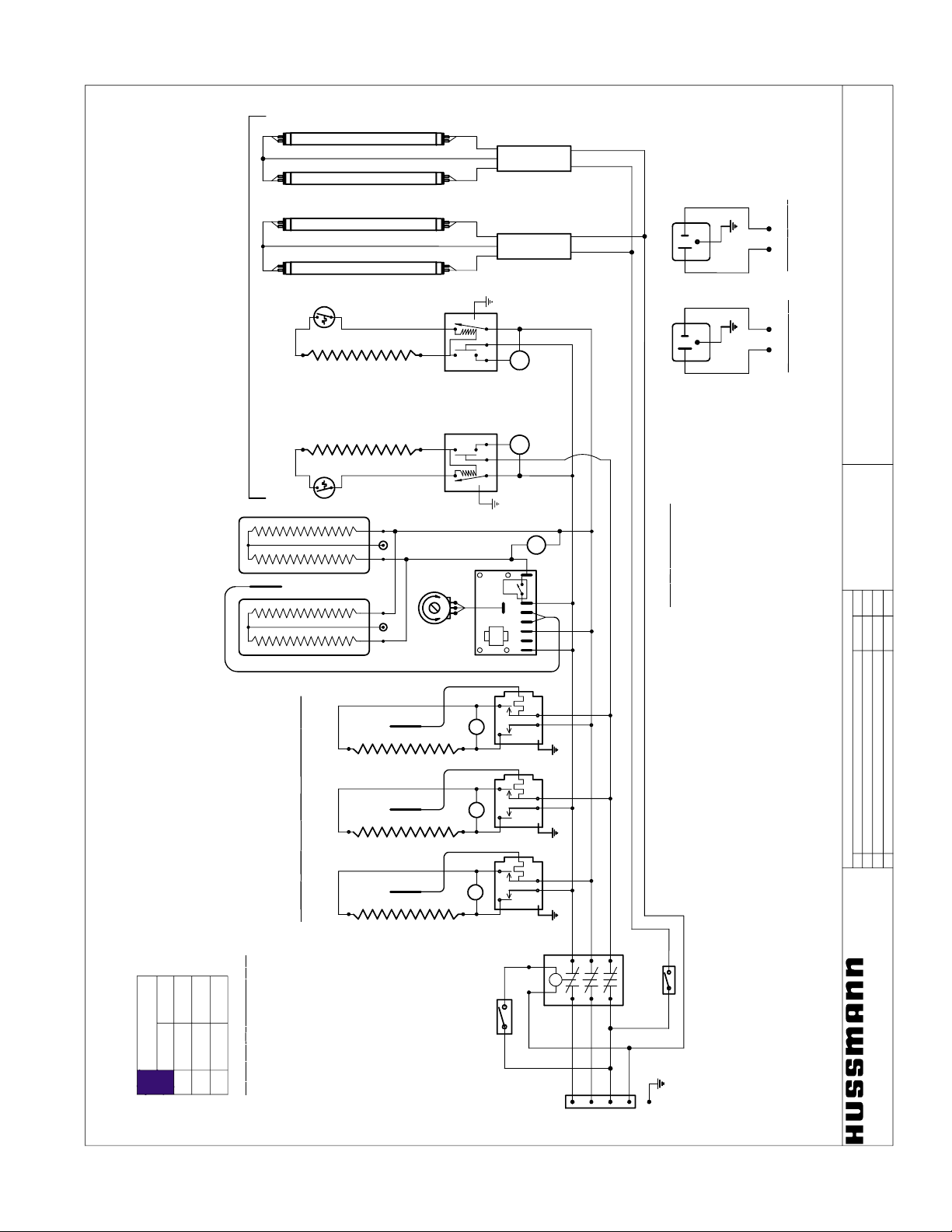
Rev. 0010
Sheet 1 of 1
final
BK
Boris Kasrel
Date:
Project Title:
Drawing No .:
Drawn By:
Next Assembly:
Drawing Title:
Date:
Hussmann Corporation
13770 Ramona Avenue
Chino, CA. 91710
(909)-590-4910
Lic.#: 644406
Revisions:
No. Description:
Checked By:
By:
01.24.2000
LIGHT
#125-01-0311
orange
blue
black
white
Optional Left
~
1
1
5
V
/
5
A
m
p'
s
~
1
1
5
V
/
5
A
m
p'
s
Optional Right
Overhead Installation
HE-19-46", 2000W/~240V
griddle
L
H1
L1
L2
H2
P
F28T5/TL830
WH3-120-164
Ballast
Contactor
#125-01-1001
Term Block
24"x48" Griddle
(2) 390W /~ 240V Htr's
6
4
2
1
5
P1
37
L
POWER
#125-01-0311
N
L3
L2
L1
G
S
L
L
Sensor
1
L
Sensor
Sensor
23
(3
) 12
x
27
Indiv
idua
l
H
ot Food
Well
1200/1600W ~208/240V
* #225-01-330 Snap-On T-Stat #20N11T002-L250
ON:183°F / OFF: 210°F
~
2
2
0
8
/
2
4
0
V-
3
Ø-
6
0
Hz
T-Stats have to be installed at each end of the case
next to outer gas spring hinge to protect O-Ring from overheating.
L
L
L
H
E
-
0
0
-
4
3
"
,
1
3
0
0
W
/
~
2
4
0
V
w
e
l
l
s
L
H1
L1
L2
H2
P
black
10 AWG
10 AWG
10 AWG
W
H
3
-
1
2
0
-
1
6
4
B
a
l
l
a
s
t
F
2
8
T
5
/
T
L
8
3
0
Loads, amp
208 V 240 V
L1
L2
L3
26.1
30.1
21.4
21.4
N
o
t
e
:
c
a
s
e
m
u
st
b
e
gr
o
u
n
d
e
d
15.3
18.7
ASH, ESH/S, OSH, RGSH-S/L
Combo Hot Food Self-Service Counters
8' Combo: 3 Individual Wells + 4' Griddle
W6000029.dft
®
41
Page 42

ASH, ESH/S, RGSH-L/S, RGSHS
Combo Hot Food Self-Service Counters
Sheet 1 of 1
final
BK
Boris Kasrel
Date:
Project Title:
Drawing No .:
Drawn By:
Next Assembly:
Drawing Title:
Date:
Hussmann Corporation
13770 Ramona Avenue
Chino, CA. 91710
(909)-590-4910
Lic.#: 644406
Revisions:
No. Description:
Checked By:
By:
01.24.2000
10' Combo: 5 Individual Wells + 4' Griddle
W6000030.dft
WH3-120-164
Ballast
LIGHT
#125-01-0311
orange
black
black
white
Optional Left
~
1
1
5
V
/
5
A
m
p'
s
~
1
1
5
V
/
5
A
m
p'
s
Optional Right
Overhead Installation
L
H1
L1
L2
H2
P
F21T5/TL830
griddle, Cal-Rod HE-19-46"
2000W/~240V
L
H1
L1
L2
H2
P
F28T5/TL830
WH3-120-164
Ballast
Cap
Circ
ui
t
2
:~
2
2
0
8
/
2
4
0
V-
1
Ø-
6
0
Hz
Contactor
N
L3
L2
L1
Term Block
G
24"x48" Griddle
(2) 390W /~208/240V
6
4
21
5
P1
37
L
S
C
a
l
-
R
o
d
H
E
-
0
6
-
7
0
"
2
2
0
0
W
/
~
2
4
0
V
POWER
#125-01-0311
N
L3
L2
L1
G
S
L
L
L
L
L
L
S
e
n
s
o
r
1
L
S
e
n
s
o
r
S
e
n
s
o
r
S
e
n
s
o
r
S
e
n
s
o
r
L
L
2345
Individua
l
H
ot Food
Well
(5) 1200/1600W/~208/240V
* #225-01-330
Snap-On T-Stat
20N11T002-L250
ON:183°F
OFF: 210°F
Circ
ui
t
1
:~
2
2
0
8
/
2
4
0
V-
3
Ø-
6
0
Hz
T-Stats have to be installed at each end of the case
next to outer gas spring hinge to protect O-Ring from 0
Overhead
W
H
3
-
1
2
0
-
1
6
4
B
a
l
l
a
s
t
F
2
1
T
5
/
T
L
8
3
0
black
orange
black
black
Loads, Amp
208 V 240 V
L1
L2
L3
13.0
15.0
10.7
12.4
N
o
t
e
:
c
a
s
e
m
u
st
b
e
gr
o
u
n
d
e
d
Circuit 2
Loads, Amp
208 V 240 V
L1
L2
L3
20.3
17.5
Circui
t
1
9.5
10.7
15.2
13.1
15.2
13.1
®
IGHT-ESH/ESHS-0010
42
Page 43
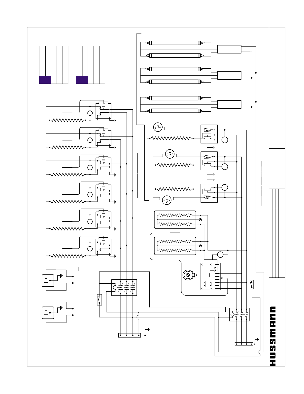
Rev. 0010
ASH, ESH/S, RGSH-L/S,RGSHS
Combo Hot Food Self-Service Counter
Sheet 2 of 2
final
BK
Boris Kasrel
Date:
Project Title:
Drawing No .:
Drawn By:
Next Assembly:
Drawing Title:
Date:
Hussmann Corporation
13770 Ramona Avenue
Chino, CA. 91710
(909)-590-4910
Lic.#: 64440
6
Revisions:
No. Description:
Checked By:
By:
12' Combo, 6 Individuale Wells + 4' Griddle
W6000031.dft
1. Update as shown.
05.03.00
BK
WH3-120-164
Ballast
LIGHT
#125-01-0311
black
white
Optional Left
~
1
1
5
V
/
5
A
m
p'
s
~
1
1
5
V
/
5
A
m
p'
s
Optional Right
Overhead Installation
L
H1
L1
L2
H2
P
F28T5/TL830
L
H1
L1
L2
H2
P
L
H1
L1
L2
H2
P
Circ
ui
t
2
-
2
0
8
/
2
4
0
V-
3
ø-6
0
Hz
40A Contactor
N
L3
L2
L1
Term Block
G
2
4
"x
4
8
"
Gri
d
dl
e
(2) 553W/~ 240V Htr's
6
4
21
5
P1
37
L
S
wells (2) Cal-Rod HE-00-43"
1300W/~240V
Cal-Rod HE-19-46"
2000W/~240V, griddle
POWER
#125-01-0311
N
L3
L2
L1
G
S
L
L
L
L
L
L
L
L
Sensor
1
L
Sensor
Sensor
Sensor
Sensor
Sensor
L
L
23456
(6
) Indiv
idua
l
H
ot Food
Well
1200/1600W ~208/240V
WH3-120-164
Ballast
F28T5/TL830
WH3-120-164
Ballast
F28T5/TL830
Term Block
Circ
ui
t
1
-
2
0
8
/
2
4
0
V-
3
ø-6
0
Hz
orange 10
black 10
blue 10
40A Contactor
L
black
white
black
white
black 10
blue 10
orange 10
black
208 V 240 V
L1
L2
L3
16.6
19.2
12.2
14.1
Note: case must be grounded
Circuit 2
Loads, amp
208 V 240 V
L1
L2
L3
24.3
21.0
Circuit 1
10.1
11.6
24.3
21.0
25.9
22.6
05.03.2000
Loads, amp
®
43
Page 44

APPENDICES
APPENDIX A. – Temperature Guidelines
1.0 Hot cases are tested to maintain all hot food at 140° - 150°.
These cases are not designed to heat up or cook food. It is the
user’s responsibility to stock the hot food cases immediately after
the cooking of the food with a pulp temperature of at least 150°
to 160°.
APPENDIX B.– Application Recommendations
1.0
The installer should perform a complete start-up evaluation prior to the
loading of food into the hot food case, which includes such items as:
a) Initial temperature performance, Griddles and Hot Wells.
b)Observation of outside influences such as drafts, radiant heating
from the ceiling and from lamps. Such influence should be
properly corrected or compensated for.
c) Complete start-up procedures should include :
1. Heat / display lamps are lighting
2. Indicator lamps on control panel(s) are working
3. Auto-fill is functioning properly (Service cases)
4. Hot Griddles are functioning.
APPENDIX C. – Field Recommendations
1.0 The most consistent indicator of display hot case performance is
temperature of the product itself.
NOTE: Public Health will use the temperature of the product in
determining if the hot case will be allowed to display potentially
hazardous food. For the purpose of this evaluation, product
temperature above the FDA Food Code 1995 temperature for
potentially hazardous food will be the first indication that an evaluation
should be performed. It is expected that all hot cases will keep food
at the FDA Food Code 1995 temperature to prevent the sale of
potentially hazardous food.
1.1 The following recommendations are made for the purpose of
arriving at easily taken and understood data which, coupled with
other observations, may be used to determined whether a display
fixture is working as intended:
a) INSTRUMENT – A stainless steel stem-type thermometer is
recommended and it should have a dial a minimum of 1 inch
internal diameter. A test thermometer scaled only in Celsius or
dually scaled in Celsius and Fahrenheit shall be accurate to 1°C
(1.8°F). Temperature measuring devices that are scaled only in
Fahrenheit shall be accurate to 2°F. The thermometer should
be checked for proper calibration. (It should read 32°F when
the stem is immersed in an ice water bath).
b) LOCATION – The thermometer must be inserted into the food
itself to acquire proper food pulp temperature.
c) READING – The thermometer reading should be made only
after it has been allowed to stabilize, i.e., maintain a constant
reading.
Loading Product: Cases should be allowed to heat up for one
hour before product is loaded.
Temperature adjustments: Allow 1 hour after adjustment has
been made before testing pulp temperature of product.
IGHT-ESH/ESHS-0010
d) OTHER OBSERVATIONS – Other observations should be made
which may indicate operating problems, such as unsatisfactory
product, feel/appearance.
APPENDIX D. – Recommendations to user
1.0 Hussmann has instructions and recommendations for proper periodic
cleaning. The user will be responsible for such cleaning, including the
cleaning of equipment within the compartment and the hot area(s).
Cleaning practices, particularly with respect to proper fixture
unloading and warm-up, must be in accordance with applicable
recommendations.
1. Allow the case to preheat for one hour prior to loading.
2. Hot foods should enter the case directly after cooking or no
lower than 150° - 160°F. The Hot Cases are not designed to
heat up or cook food.
3. Self Service - be sure to display product in single layer in
direct contact with heating surface and/or wire rack.
4. All griddle type units are designed to maintain temperatures above
the FDA guideline of 140°F. This is product temperature, not air or
griddle temperature. Due to the open design of these units, they
must be loaded with product for proper operation. When units are
empty, they experience rapid rise of heated air from air outside the
case. This action gives empty units a false, lower than desired,
temperature reading. Loading the case traps the air at the griddle,
raising temperatures to the 165°F to 185°F range, keeping product
well above the FDA guidelines. Remember, these units must be
loaded with product to maintain safe product temperature.
5. Check the food pulp temperature frequently with a thermometer to make sure it is at the proper holding temperature. Hot
foods should be at 140°. The thermometer must be inserted
into the food itself for the proper temperature.
6. Do not display more food than will be sold within a 4 hour
period.
7. When restocking, bring older food to the front.
8. Clean spills as soon as they happen.
9. Fingerprints and food splatter will drastically shorten bulb life.
Clean splatter off the bulbs immediately with a soft cloth.
When handling bulbs, wear cotton gloves or use a cotton rag /
towel.
10. When “freshening” foods such as macaroni and cheese with
added water, heat the water in a clean container until it is
10° to 20°F above the desired holding temperature of the
food. This will keep the food at a safe serving temperature.
Depending on the amount of water, the temperature can drop
10° to 20° in as little as five minutes.
11. When transferring hot foods in the heated merchandiser to
clean pans, preheat the clean pan. Transferring hot foods to
room temperature pans can cause the temperature of the food
to drop 20° or more thus causing food to be at an unsafe
serving temperature.
12. Clean spills as they happen simply by wiping with a cloth. Be
sure to use a dry cloth on very hot surfaces to prevent steam
burns.
44
Page 45

Rev. 0010
13.Turn the equipment off and allow to cool before cleaning.
14.To remove “baked-on” splatter from Stainless Steel, the
following may be used
Grade F Italian Pumice Scour or rub with a damp cloth
Liquid Nusteel Scour with a small amount of a dry
cloth
Paste NuSteel
Household Cleaners Rub with a damp cloth
Coopers Stainless Steel Cleaner
Allen Stainless Steel Polish
45
Page 46

IGHT-ESH/ESHS-0010
Limited Warranty
This warranty is made to the original user at the original installation site and is not transferable.
Hussmann merchandisers are warranted to be fr ee fr om defect in material and w orkmanship under normal use and
service for a period of one (1) year from the date of original installation (not to exceed fifteen (15) months from the date of
shipment for the factory). Hussmann Impact
the abov e criteria. Hussmann’s obligation under this warranty shall be limited to repairing or exchanging any part or parts,
without charge F.O.B. factory or nearest authorized parts depot within said period and which is proven to the satisfaction of
the original manufacturing plant warranty group to be thus defective.
Hussmann covers the entire case or r efrigeration product and all its components (except for lamps, driers, fuses, and
other maintenance type replacement parts) for the one (1) year warranty period.
Additionally, Hussmann warrants for a total period of three (3) years all sealed, multi-glass assemblies except those
used in sliding doors on closed meat display cases. If within three (3) years from the date of installation (not to exceed thirtynine (39) months from the date of shipment from factory), it shall be proven to the satisfaction of the originating factory
warranty group that there is impaired visibility through the multi-glass assemblies thereof caused by moisture between the
glasses, the multi-glass assembly will be replaced free of charge, F.O.B. factor y. This additional warranty excludes accident,
misuse, or glass breakage.
On Hussmann manufactured self-contained display cases, Hussmann agrees to repair or exchange, at its option, the
original motor/compressor unit only with a motor/compressor of like or of similar design and capacity if it is shown to the
satisfaction of Hussmann that the motor/compressor is inoperative due to defects in factory workmanship or material under
normal use and service as outlined in Hussmann’s “Installation Instructions” which are shipped inside new Hussmann equipment. Hussmann’s sole obligation under this warranty shall be limited to a period not to exceed five years from date of
factory shipment.
On Hussmann refrigeration systems, an additional (4) year extended warranty for the motor/compressor assembly
is available, but must be purchased prior to shipment to be in effect. Hussmann reserves the right to inspect the job site,
installation and reason for failure.
The motor/compressor warranties listed above do not include r eplacement or r epair of controls, relays, capacitors,
overload protectors, valve plates, oil pumps, gaskets or any external part on the motor/compressor replaceable in the field, or
any other part of the refrigeration system or self-contained display case.
THE WARRANTIES TO REPAIR OR REPLACE ABOVE RECITED ARE THE ONLY WARRANTIES, EXPRESS, IMPLIED OR STATUTORY, MADE BY HUSSMANN WITH RESPECT TO THE ABOVE MENTIONED EQUIPMENT, INCLUDING ANY IMPLIED WARRANTY OF MERCHANTABILITY OR FITNESS, AND HUSSMANN NEITHER ASSUMES NOR
AUTHORIZES ANY PERSON TO ASSUME FOR IT, ANY OTHER OBLIGATION OR LIABILITY IN CONNECTION WITH
THE SALE OF SAID EQUIPMENT OR ANY PART THEREOF.
THIS WARRANTY SHALL NOT APPLY TO LOSS OF FOOD OR CONTENTS OF THE EQUIPMENT
DUE TO FAILURE FOR ANY REASON. HUSSMANN SHALL NOT BE LIABLE:
• For payment of labor f or any removal or installation of war ranted parts;
• For any repair or r eplacements made without the written consent of Hussmann, or when the equipment is installed or
operated in a manner contrary to the printed instructions covering installation and service which accompanied such
equipment;
• For any damages, delays, or losses, direct or consequential which may arise in connection with such equipment or part
thereof;
• For damages caused by fire, flood, strikes, acts of God or cir cumstances beyond its contr ol;
• When the equipment is subject to negligence, abuse, misuse or when the serial number of the equipment has been
removed, defaced, or altered;
• When the equipment is operated on low or improper v oltages
• When the equipment is put to a use other than normally recommended by Hussmann (i.e. deli case used f or fresh
meat);
• When operation of this equipment is impaired due to improper drain installation;
• For payment of r efrigerant loss for any r eason;
• For costs related to shipping or handling of replacement parts.
Hussmann Corporation, Corporate Headquarters: Bridgeton, Missouri, U.S.A. 63044 August 1, 1998
Modular Coils are warranted for a total of five (5) y ears based upon
46
Page 47

Rev. 0010
Service Record
Last service date: By:
/Chino
Additional copies of this publication may be obtained by contacting:
Hussmann® Chino
13770 Ramona Avenue • Chino, California 91710
(909) 628-8942 FAX
(909) 590-4910
(800) 395-9229
The MODEL NAME and SERIAL NUMBER is required in order to provide y ou
with the correct parts and information for your particular unit.
They can be found on a small metal plate on the unit.
Please note them below for future reference.
MODEL:
SERIAL NUMBER:
47
 Loading...