

Page 1
MODEL: GSVM – Self Contained Medium
Temperature Cases for Dairy,
Beverages, and Deli Products
OII - GSVM
January 2005
Operating and Installation
Instructions
Page 2

TABLE OF CONTENTS
Page
Introduction 4
Inspection 4
Location and Clearance 4
Skid 4
Leveling 5
Sealing 5
Access Panel Removal 5
Legs 5
Serial Plate 5
Air distribution and Product Loading 6
Power Requirements 6
Electrical Box 6
Power Switch 6
Defrost Time Clock 6 & 7
Connections 7
Drains 7 & 10
Dimensions 8
Electrical 8
BTU Capacity 8
Shelving Maximum Weight Capacities 8 & 9
Temperature Control 9
Condensing Unit 10
Shelves 10
Thermometer 10
Lighting 10
Light Switches 10
Ballasts 11
Cleaning Exterior, Interior, Stainless Steel Surfaces 11
2
Page 3

TABLE OF CONTENTS CON’T
Page
Refrigeration 11
Leak Testing 12
Evacuation 12
Temperature Control 13
Evaporator Fan Motors 13
Trouble Shooting Charts 14 – 16
GSVM Accessories 16 – 17
Warranty and Parts Information 17
Wiring Diagrams 18 – 21
This GSVM case was manufactured in Gloversville, New York. Our phone #’s are (518)
725-0644 for New York State residents and our toll free #800-753-7790 for outside New
York – should you have further questions.
3
Page 4

y
INTRODUCTION –
The Hussmann Model GSVM open
vertical merchandiser offers versatility in
the display of medium temperature (3541ºF) products such as diary products,
prepared salads, pizza and fresh entrees
that are pre-chilled in a cooler.
So that you can realize maximum
benefit from this fine piece of equipment
we urge both you and your installer to
carefully read and follow this brief set of
instructions prior to installation of the
equipment.
INSPECTION –
The equipment has been skidded
and crated prior to shipment from the
factory. It is the carrier’s responsibility to
deliver it to you in good condition until
such time as you sign for it.
Upon receipt of the cabinet,
examine the packaging for damage. If the
packaging is damaged, make specific
notation on the delivery ticket as to the
location and extent of damage prior to
signing for the piece.
Carefully remove packaging and
examine the cabinet for damage. If
damage is found, contact the delivering
carrier immediately and request that his
agent prepare an inspection report for the
purpose of filing a claim. THIS IS YOUR
RESPONSIBILITY, NOT THE
FACTORY’S.
Save all packaging materials and
move the cabinet as little as possible prior
to inspection.
LOCATION and CLEARANCE –
It is important that careful
consideration be given to locating the
cabinet away from an area where direct
sunlight would shine into the fixture, or
where drafts from air conditioning grilles,
fans, and open doors could affect its
operation.
The GSVM4060 and 4072 have
front condenser air intake and discharge.
A minimum distance of two feet must be
left open in front of the case so that air
discharge and intake to the condensing
unit is not obstructed.
The GSVM5272 model requires a
5" minimum clearance behind the case
and clear above the case since it has
straight through condenser air flow.
Brackets are provided for field
attachment to obtain the 5" spacing.
–
SKID
The skid should be left on the
cabinet until it is near its final location.
The skid provides protection for both case
and floor.
The skid is removed b
raising one
end of the case approx. 6", block securely
and remove the 2 skid bolts on the raised
end – then screw back into the holes 2 leg
levelers.
4
Page 5
The procedure is repeated on the opposite end. When the leg levelers are in
place, the case may be slid off the skid and
placed in its final location.
LEVELING
–
The cabinet must be leveled pr operly
to insure full drai nage of condensate water
from the evaporator coil. Level the case
fr om front to rear and end to end. Standard levelers, packed inside the case, or optiona l legs can be provided for this purpose.
SEALING
–
Once the case is properly leveled, the
cas e should be sealed to the flo or as s hown
in the follow ing drawing, using an NSF approved material such as General Electric
RTV-102 sil icone s eal er or equivalent .
Silicone Sealant
Floor
ACCESS PANEL REMOVAL
–
The louvered access panel on the
lowe r fr ont of the c ase pro vid es access to
the condensing unit, electrical box and condensate pan. Remove panel by removing
screw at bottom and lift ing up and pulling
forward.
DRAINS –
R em ote draining is not re quired in
self-contained models. The condensate
water from the evaporator drains out
through the bottom of the cabinet,
through a copper trap atta ch ed to the underside a nd into the condensing unit compartment to a heated condensate pan.
Until this trap gets filled with water fr o m th e ini t i al d e fros t, there may b e a
small frost buildup in the coil area on
startup, whi ch shoul d disappear after the
first defrost. The pan uses a thermistor to
sense the presence of water in the pa n and
adjusts the a mount o f heat required to
evaporate the wa ter.
LEGS (OPTIONAL)
-
If required by Health Inspectors
the levelers can be removed and replaced
with NSF Approved legs to raise the cas e 6
inche s for cl ea ning purpos es. An opti onal
skirt kit can be provided to cl ip on to the
legs.
SE RIAL PLATE
–
The seria l plate is lo cated on the interior top wall of the cabinet towards the
left end. It contains all pert i ne nt information su ch as m odel , cabi net seri al number,
am pera ge rating, refrigera nt type and
charge , etc. This i nforma ti on wi ll b e
needed to install, service, or order parts
for this piece of equipment.
5
Page 6
AIR DISTRIBUTION and PRODUCT
LOADING –
This cabinet has a forced-air
circulation system. Air flows through the
back wall over the product on the shelves,
as well as out the honeycomb diffuser
located above the product, across the face
of the product (air curtain) and into the
return air grill.
Do not load product so that it
extends over the shelf edges or over the
return air grille.
POWER REQUIREMENTS –
The GSVM Models are equipped
for operation on a 115/60/1 power supply.
See chart in specifications for
requirements.
It is very important for the safety of
both you and your customer to have each
circuit properly grounded. A qualified
electrician should perform all wiring in
accordance with the National Electrical
Code and/or all local codes. Separate
circuits are recommended for each case in
order to prevent product loss due to
overloading or malfunction of other
equipment on the same circuit. For proper
operation of equipment, voltage as
measured at the compressor must not vary
more than 5% from the cabinet serial plate
rating. If either a high or low voltage
condition exists, contact your electrician,
local power company, or equipment
manufacturer.
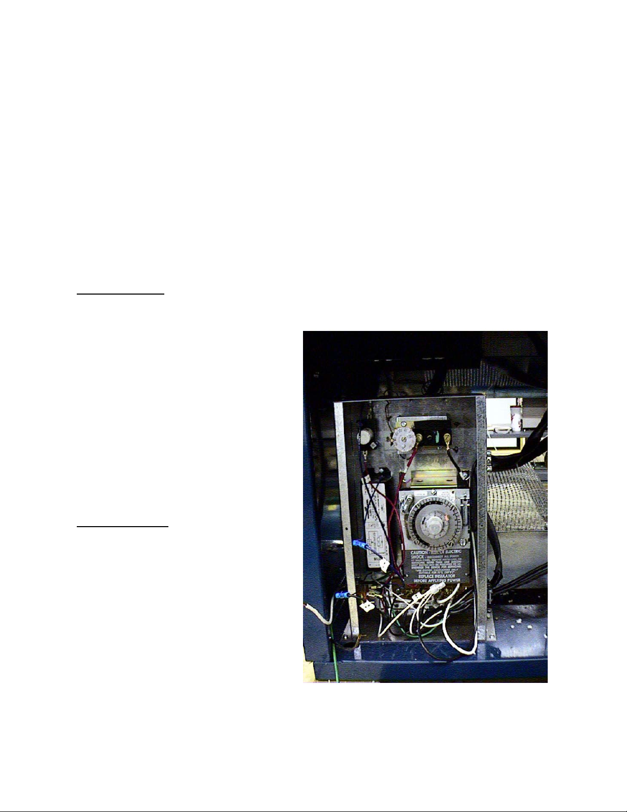
ELECTRICAL BOX –
The electrical box is located behind
the louvered access panel. The box is
capable of sliding out for service after the
hold down screw is removed.
The box contains the power switch
and defrost time clock.
POWER SWITCH –
The main power switch is located
behind the front louvered access panel on
the side of the electrical box. This power
switch controls all power to the case. THE
CABINET POWER SWITCH MUST BE
IN THE OFF POSITION BEFORE
STARTING ANY CLEANING OR
SERVICE WORK ON THE
EQUIPMENT.
DEFROST TIME CLOCK –
The time clock, located in the
electrical box, provides a definite off-time
so that the evaporator will clear itself of
frost.
The clock is provided with pins to
initiate defrost. The failsafe setting sets
the length of defrost (from 2 minutes
minimum to 110 maximum).
The clock is factory pre-set for 3
defrosts (at 6 a.m. , 2 p.m. and 10 p.m.)
on the 4060 and 4072 at 20 minutes
6
Page 7
each. There are 4 defrost on the 5272 (2
a.m., 8 a.m., 2 p. m., and 8 p.m. ) at 30
minutes e ach
Additional defrost may be required for cases located in high humidit y
or high usage cases. If possible, avoid
setting a defrost during the day, or peak
usage periods. THE CLOCK TIME
PO IN TER SHOULD BE SET TO THE
CORRECT TIME OF DAY WHEN
THE CABINET IS REA DY TO BE
STARTED.
S e tting the ti me r
– Extra pins are pro-
vided with the timer.
♦
Put pin in ho le of dial face a t the time
yo u wi sh the cabin et to d efr ost. Note
that there is an AM and PM sect ion
on the dial face. Be sure the pin is
tight.
♦
Set the length of time for the defrost
(failsafe). Push down on the adjustment and slide it to the length of time.
Do not s et th e time longer than 60
minutes.
♦
Set t h e time point er to the prop er
time of day and start cabinet.
CONNECTIONS
-
a. C heck c abinet thoroughly for loose
nuts and bolts and electrical connections.
b. Inspect the refrigera tion lines for any
visible dama ge or chafing.
c. Replace electrical box cover.
d. Replace the louvered acce ss panel.
e. Star t the cabinet and a llow to pull
down to operating temperature befo re
loading.
7
Page 8

SPECIFICATIONS –
DIMENSIONS
Exterior
Model Length Width Height
GSVM-4060 40" 30 5/8" 60"
GSVM-4072 40" 30 5/8" 72"
GSVM-5272 52" 30 5/8" 72"
ELECTRICAL
MODEL NO. Volts/Hz/Phase REFRIGERANT RUN FUSE POWER
TYPE AMPS AMPS CORD
GSVM4060 115/60/1 R-134a 15 20 YES
GSVM4072 115/60/1 R-134a 17 25 NO
GSVM5272 115/60/1 R-134a 20 25 NO
GSVM5272 115/60/1 R-404A 17.25 25 NO **
** The GSVM-5272 changed to R404A in January 2000. Check the Serial Plate to verify
the correct refrigerant.
Note: Applies to the GSVM4072 & 5272 Models Only-Drain Plumbing hookup
recommended. Optional condensate is available if there is no access to drain plumbing.
Condensate pan must be field installed and requires a dedicated 15 amp, 120-volt circuit.
See page 15 for optional drain pan specifications.
BTU CAPACITY
RATING TEMPERATURE ºF
BTU/HR EVAP COND AMBIENT
GSVM-4060 6200 20 110 90
GSVM-4072 6250 20 110 90
GSVM-5272 6300 20 110 90
Cabinets use R-134A or R-404A
SHELVING MAXIMUM WEIGHT CAPACITY (LBS) -
The following is a tabulation of the maximum evenly distributed weights that can be
applied on the respective shelves. They greatly exceed most normal food products that
could be displayed in the case
8
Page 9

Flat 1 1/2
Upslope 17ºTilt 30ºTilt
Bottom Sheet Metal Area 250# N/A N/A
Stand. 13”/15” shelves 250# 250# 75#
Stand. 13”/15” shelves w/optional
upslope 6º adapters 125# N/A N/A
Optional Wire Baskets 200# 100# 30#
See SHELVES for the special
loading instructions. Air flows out of the
OPERATION and MAINTENANCE -
It is important that the two
previous sections of this installation
booklet have been read and followed
carefully before attempting to start up
the equipment.
A thorough inspection should be
made prior to start up to assure that
there are no loose nuts, bolts, electrical
connections or refrigeration lines
rubbing or chafing. Turn the power
switch to the ON position. ALLOW
system to reach normal operating
temp.prior to
loading any
product.
This cabinet
has a
forced-air
curtain that
flows over the
top of the
product.
honeycomb diffuser located above the
product, across the product, and into the
return duct. The honeycomb can be
removed for cleaning.
TEMPERATURE CONTROL –
Interior cabinet temperatures are
controlled through the use of a bulb and
capillary type temperature control. The
control is located in the electrical box.
The sensing bulb is mounted on the
top of the evaporator coil on the 4060 and
4072. On the 5272 it is located on the rear
wall behind the evaporator coil. Be sure
to disconnect power supply prior to any
service work on the control.
The control is factory pre-set
between 19º and 21ºF for the GSVM4060,
4072 and - 26º to 28ºF on the GSVM5272 to
maintain between 35º and 40ºF interior
cabinet average temperatures.
The differential is set at 8-10ºF or
alittle over halfway towards “MAX”.
Donot adjust lower or evap. icing will
occur. It can be adjusted to other desired
temperatures by turning the dial to the
corresponding dial face temperatures. The
indicated dial temperature will not directly
9
Page 10

correspond to the actual cabinet t emperature due to the bulb loca tion and depending on various conditions, a certain amount
of time lag wil l be noticed between the new
sett ing and the resulting temperature.
CO NDENSING UNIT
–
A regular program should be set up
f or cleaning the fin-and-tube condenser.
No rmally, this cleaning is required every 3
t o 4 months, but t he individual store appl ication may s horten or lengthen this time
perio d. Dust and dirt a c cumulation can
cause serious efficiency loss.
A c ce ss is gained to th e unit area b y
removing the louv ered gril le. Before attempting to slide ou t conden sing u n it you
must first remove the screws from the co ndenser unit baffles. The unit slides forward to facilitate cleaning and for service.
Care should be taken when pushing the
unit back in, to insure that the pullout coil
does not become kinke d or damaged in
some way . The baffle screws must be r eplaced after sliding the condensing unit
back into po sition. Double check to make
sure the drai n hose is in the drain pa n before putting the access grille back on. The
rear access panel is also removable if it is
necessar y to work at the back of the case.
SHELVES
–
The GSVM4060 cabinet is equipped
with 2 standard shelves for the display of
y our product . The 13” shelf should be located at the top and 15 ” shelf should be loca ted belo w it. The GSVM5272 and 4072
has an additional 13” shelf as standard
which should be located above the 15”
shelf also.
The shelve s should be positioned so
they do not protrude into the front (top to
bottom) air c urtain. Do not use deeper
shelves or allow product to protrude over
the shelves into the air curtai n.
THERMOMETER
–
A solar thermometer is pro vided
that re gi sters degrees ºF. Th e t he rmom eter is located i n the front center.
A solar powered thermometer is
equipped with each cabinet. The thermometer is located in the top front center
of the cabinet interior. Tempera t ure is displayed i n Fah renheit degrees as standar d.
Ce l sius d is pla y i s available as a n opt ion .
The thermo meter may be repla ced
by re mo vi n g the two s cre w s secur in g the
thermometer to is mounting bracket. Remove the sen sing element from the clip.
Install the new thermometer in reverse order.
To clean the sensing element o f the
thermometer, follow the same procedure
as replacement. Cleaning of the element is
accomplished by using water and mild detergent. Be sure to wipe the element clean
of any residues so proper temperatures are
displayed.
10
Page 11

–
–
–
LIGHTING
Interior lighting is provided by a
cool white fluorescent bulb under the top
header (standard), and additional lights
under each shelf. The tubes are sleeved to
maintain proper heat around the bulb for
maximum light intensity and to protect the
product in case of breakage.
The tubes can be replaced without
removing shelves or product. To replace
the bulb, twist th e bulb and slide the
prongs clear of the lampholder. When reinstalling this type of bulb, be sure the
prongs on the bulb twist and lock into
place.
LIGHT SWITCH (es)
-
The standard cas e has one upper
light with a switch located under the top
left end behind the honeycomb. Additionally, the lighting on each shelf has a sep arate switch located under the center of
each shelf.
BALLAST (s)
-
The ballast for the top standard
light is located in the e lectrical box. Access
is gained by removing the access panel.
Access to the shelving ballasts is gained by
removing the respective shelf (after u nplu g ging the harness), and removing the
three screws from the ballast cover.
CLEANING EXTERIOR
When cleaning the exterior of the
cabinet, use a soft cloth or sponges with
water and a mild detergent. Rinse and
wipe dry. Do not use an abrasive cleanser
on the painted surfaces as this will mar the
finish.
For plexiglass windows, use an a pproved plexiglass cleaner such as Craftics
20/20 Plasti -Cleaner.
CLEANING INTERIOR
For cleaning the interior of the
product compartment, remove the product,
disconnect the electrical power, and allow
cabinet to warm to room temperature. Use
a soft cloth or sponge with a mild detergent
to wash the interior.
The drainage area and drain should
be checked to insure that they have not become clogged. If the condensate drain hose
is removed from the electric condensate
pan for cleaning, it must be reinstalled
prior to operating the case. Do not use an
abrasive cleanser on the painted surfaces
GSVM-4060 only has Electric Condensate Pan as Standard
Wipe dry before restarting the cabinet. The time clock (see Defrost Time
Clock section) should be reset to the correct
time of day. Allow the cabinet to cool down
to proper temperature before reloading
product.
11
Page 12

CLEANING STA INLESS STEEL
SURFACES
–
Generally soap and water will be
sufficient for most cleanings when do ne often and regularly. When necessa ry, several cleaning agents can be used. Some of
thema re Comet, B ab -O , Liquid NuSteel ,
Cooper’s Stainle ss Steel Cleaner, and Allen’s Stainless Steel Cleaner.
REFRIGERATION
–
The GSVM models employ a refrigeration system using a hermetic compressor. The GSVM4060 and GSVM4072 sys tems employ a capillary tube for refrigerant flow control. The capillary tube is solder ed t o the suction line pull-out coil for
proper heat exchange. If the capillary
should become plug ged or damaged fo r
some reason it is best to replace the whole
heat exchanger with a new one. Consult
the factory for the proper replacement.
The GSVM-5272 employs a bleed
port type expansion valve for proper refrigerant co ntro l.
As stated previously, these cases are selfcontained with the conden sing unit
mounted at the bottom. They are
equipped with a hermetic compressor and
a capillary tube. The condenser is of fin
a nd tube const ruc tion and SHOULD BE
PERIODICALLY CLEANED TO MAINTAIN EFFICI ENT O PERA TION.
If for any reason the cabinet must
be recharged, consult the seria l plate found
insi de the cabinet f or the pro per refrigeran t charge an d we ight.
If it should become necessary to leak
test t he system, please adhere to the following no tice:
BECAUSE OF THE CFC ATMOSPHE RIC CON SIDERATIONS BEIN G
TAKEN TODAY, WE A SK THAT LEAK
TESTING BE DON E WITH REFRIGERANT 22 MIXED WITH NITROGEN
LEAK TESTING
–
The test gas cylinder must be
equipped with a pressure gauge and regulator so that system test pressures do no t
exceed maximum allowable limits. Do not
ever use anything other than a R-22/
Nitrogen mixture for leak testing.
Attach a refrigerant test gas cylinder to your service manifold and connect
the manifold to the charging port on the
li qu id li ne va lv e.
Charge an R-22/Nitrogen mixture
into the s yst em, raisi ng the pressure to the
unit’s nameplate for the low side and high
side pressures. U sing an e lectron ic detector, carefully check the entire system for
leaks. Take speci al care to inspect all
brazed and flare connections.
EVACUATION
–
After the system is proven leak
tight, thoroughly ev acu ate the system according to the following procedure:
a. Discharge the refrigerant-nitrogen mix-
ture, allowing it t o blow fro m the system as rapidly as possible , into an y
empty cylinder.
12
Page 13

Be sure that all service valves are open to allo w all of the mixture to be discharged.
b. Connect a deep-drain vacuum pump to
both the high and low side of the system.
Pul l a v acuum on the syst e m to at le a st
1 5 00 microns.
c. Break the vacuum by adding refrigerant
into the system until the pressure is above
0 psig. Always charge the refrigerant line
int o the system through a new drier in the
charging manifold line. A 16 cubic inch
drier is sufficient f or this purpos e.
d. Repeat steps 2 and 3 two more times, the
third time evacuating the system to 500
microns.
The follow ing pressu res are o ptimum
when the cas e in a 75º to 80ºF ambient and is
running fro m 35º to 40ºF c a bin et te mp er ature an d are for reference onl y:
MODEL NO. REFRIGERANT SUCTION PRESSURE HEAD PRESSURE
TYPE (psig) (psig)
GSVM4060 R-134a 12-15 130-150
GSVM4072 R-134a 12-15 130-150
GSVM5272 R-134a 14-18 130-150
GSVM5272 R-404A 40-50 310-320
Consult the serial plate for the correct refrigerant charge. This charge is critical and
should be weighed in.
TEMPERATURE CONTROL –
T he temperature contro l is located in
the electrical box. The sensing bulb is located o n the left h and end of the low er back
wall.
When replacing make sure the bulb
is in the proper location and that the hole in
the liner is properly sealed after the replacement has been made.
The control is adjus table from –3 0º to 50ºF
(di al face m arking ). The a ctual ca b inet temperature is approximately 6 to 9º warmer
than the control setting so this must be
taken into cons iderati o n.
The control also has an adjustable differential that determines the difference between
the cut-in and cut-out temperature. This is
adjus tab le from 5 to 20º. The fact ory s et ting is from 8-10º to insure proper off time
to keep the evapora tor from icing.
EVAPORATOR FAN MOTORS
–
To replace an evaporator fan motor,
the product must be removed from the
cabinet and the bottom shelf also removed.
Next, remove the plate covering the
fans by removing the 2 screws, and 4 bolts
holding this in place. T he fans a re now ac-
13
Page 14

TROUBLE SHOOTING CHARTS
TROUBLE PROBABLE CAUSE SOLUTION
Compressor will not start no
noise
1. Power disconnected 1. Check service cord or
wiring connection.
2. Blown fuse or breaker 2. Replace fuse or reset
breaker
3. Defective or broken
3. Repair or replace
wiring
4. Defective overload 4. Replace
5. Defective temperature
control
5. Replace
Compressor will not start,
cuts out on overload
1. Low voltage 1. Check voltage at cabinet,
should not be more than 5%
below rating.
2. Defective compressor 2. Replace
3. Defective relay 3. Replace
4. Restriction (pinched cap
4. Repair or replace
tube)
5. Restriction (moisture) 5. Leak check, replace drier
evacuate and recharge
6. Condenser blocked with
6. Clean condenser
dust and dirt
7. Defective condenser fan
7. Replace
motor
Warm storage temperature 1. Temperature control not
1. Reset control
set properly
2. Short of refrigerant 2. Leak check, replace drier
evacuate and recharge
3. Cabinet location too
warm
3. Move to cooler location or
correct excessive heat source.
14
Page 15

4. Refrigerant overcharge 4. Purge system, evacuate
and recharge.
5. Low voltage, compressor
cycling on overload
5. Check voltage at
compressor should not be
more than 5% below rating
Compressor runs
continuously. Product too
1. Short of refrigerant 1. Leak check, replace drier,
evacuate and recharge
warm
2. Inefficient compressor 2. Replace
Compressor runs
1. Defective control 1. Replace
continuously. Product too
cold
2. Control sensing element
2. Assure proper contact
not in positive contact
3. Short on refrigerant 3. Leak check, replace drier,
evacuate and recharge.
TROUBLE SHOOTING LIGHT CHART
PROBLEM SOLUTION
Lights won’t start 1. Check light switch
2. Check continuity to ballast
3. Check to see if bulbs inserted properly in sockets
4. Check voltage
Lights flicker 1. Allow lamps to warm up
2. Check lamp sleeve for cracks
3. Check sockets for moisture and proper contact
4. Bulb replacement may be necessary
5. Check voltage
6. New bulbs tend to flicker until used
15
Page 16

Ballast Hums 1. Check voltage
2. Replace ballast
GSVM ACCESSORIES
The following is a description of the various accessories available for the GSVM,
including sketches, where applicable of the many shelving/wire goods items available.
CASTER KIT – Consists of 5" braking casters, which screw in to the standard threaded
holes in the four corners under the case occupied by the standard leg levelers, which will
have to be removed. The kit will add 5 5/8" to the height of the case.
LEG KIT
– The legs also go into the same holes as the standard levelers, which will have to
be removed. The legs are adjustable and will add 5 5/16 to the height of the case. The skirt
kit requires the use of these legs.
4-SIDED SKIRT KIT
– As stated, this is a 4-sided skirt that will enclose the open area
under the case when the leg kit is used. It clamps onto the legs.
NIGHT COVER – This is a clear, 5 mil. thick, polyester shade type of cover that will cover
the face of the case. It will fasten to the top of the case and be drawn to a snap fastener in
the area above the front bumper. The cover, although loose fitting on the ends, will
conserve energy during periods when the store is not open. The cover is standard on the
GSVM5272 effective August ’96.
WRAP-AROUND BUMPER KIT – This bumper replaces the standard front bumper and
warps around both sides of the case at the standard height of 22" to the centerline of the 2
1/4" wide bumper.
COLORED ACCENT PANEL
– This panel can be (a) the top front panel over the product
or (b) the panel behind the bumper or (c) the access panel below the bumper panel, or any
combination of these.
SHELF END TRIM KIT – Consists of (4) painted steel ends for the standard 13" and 15"
shelves. This trim conceals and protects the exposed ends of the shelves, and attaches by
two snap fasteners supplied with each trim piece for the 4060. The 4072 and 5272 need 6.
HIGH HUMIDITY CONDENSATE PAN
– (For GSVM4072 & 5272) This is a 1,000 watt,9
amp pan with a 6ft-9 in 115v power cord attached. Dedicated circuit required.
16
Page 17

SHELF UPSLOPE ADAPTER KIT – This kit consists of (4) zinc coated wire adapters to
increase the two standard shelves’ upslope from 1 1/2º to 6º.
PRICE TAG MOLDING KIT
– This kit consists of aluminum price tag molding for the
standard shelves. This molding will hold both 1" and 1.235" standard price tags. (Note
that the standard shelves accept 1.235” tags).
WIRE PRODUCT STOP KIT
– This kit consists of a 2” high chrome plated open wire
stops for the standard shelf. This stop is mounted under tension and should not be
confused with the wire front in the partition kit.
WIRE PARTITION KIT – This is a free standing wire system, which attaches to the
standard shelves, and consists of a wire front (different from the Product Stop), two wire
sides, and two partitions from the front to back, all chrome plated and 3" high.
WIRE CROSS DIVIDER – This is a 3" high x 4" long divider that could be ordered to be
used with the Wire Partition Kit above, in whatever quantities are desired.
WIRE BASKET KITS – One kit is available to replace the top 13" shelf (s) and another is
available to replace the bottom 15" shelf. Each kit consists of a wire basket, (2) brackets,
and two dividers, which could also be used as ends. These parts are zinc plated. The
baskets have an 8" high back and a 4" sloped front.
WIRE BASKET DIVIDERS – These are additional dividers which can be used with the
Wire Basket Kit to obtain additional partitioned areas in the baskets.
ADDITIONAL LIGHTED SHELF – This consists of an additional 13" lighted shelf that
can be positioned between the two standard shelves. It is the same construction as the top
standard 13" shelf.
WARRANTY AND PARTS INFORMATION
IMPORTANT – Please read carefully to assure prompt and accurate service.
ORDERING PARTS REPLACEMENT –
Contact your nearest Hussmann Distributor.
Always specify model and serial number of cabinet.
If correct part number is not know, give a clear description of part itself and its function in the cabinet or
remote unit.
17
Page 18

WARRANTY PARTS PROCEDURE
Same as first three items in Ordering Replacement Parts Procedure.
Give original installation date of cabinet and, if possible, forward a copy of the original invoice or delivery
receipt.
All shipments of in-warranty replacement parts will be invoiced from the factory until such time as the
defective part is returned and proved to be defective by our Quality Control Department.
Contact your Hussmann Distributor for instructions on returning in-warranty parts.
Warranty parts must be returned to the factory within 30 days of date of failure to assure proper disposition.
Lack of any of the above information may result in the shipment of the wrong part, or a delay in shipment.
COMPRESSOR REPLACEMENT PROCEDURE –
Replacement compressors will not be shipped from the Hussmann factory. They may be
obtained from you nearest Copeland Wholesaler.
Your wholesaler will replace, free of charge, any compressor found to be defective within
twelve months of installation, not to exceed twenty months from the date of
manufacture – as determined by the compressor serial number on the compressor serial
plate.
For any defective compressor beyond the twelve or twenty month time period, a salvage
value credit will be given too partially offset the invoice for the replacement.
To obtain reimbursement forward to: Hussmann Corporation
140 East State Street
Gloversville, NY
12078
the following information:
The cabinet model and serial number
2. A copy of the wholesaler’s invoice, along with a copy of the salvage value credit.
18
Page 19

RED
LIGHT SWITCH
UPPER LIGHT
LAMP
RED
BLK
BLK
WIRE HARNESS
EVAP. FANS
LAMP
BALLAST
LAMP
BALLAST
LAMP
S
SHELF
RED
BLK
LIGHT
TEMP. CONTROL
TIME CLOCK
OPTIONAL
PROTECTOR
#1 RELAY
COMPRESSOR
C
1
2
COND.
FAN
T
LIGHT SWITCH
BLK
WHT
BLK
S
STD.
GRN
SHELF
RED
STARTER
S
BLU
BLU
2
4
N
BLK
1
3X
WHT
WHT
LIGHT
LIGHT SWITCH
BLK
WHT
S
STD.
WHT
WHT
BLK
BALLAST
11 12
9 10
25 26
23 24
ELEC-TRON
BLK
GRD
WHT
7 8
5 6
3 4
1 2
3-S-226
SHELF
LIGHT
BLK
CONDENSATE PAN
BALLAST
ONE LIGHTED SHELF
BLK
WHT
LIGHT SWITCH
115 V
60 Hz
1 Ph
REV.
POWER CORD
DATE
S3
POWER SWITCH
WHT
GRN
BLK
S1
GSVM 4060
TOLERANCES UNLESS
XXXX-XXXX
SHEET
SIZE
C
OTHERWISE SPECIFIED.
FRACTIONAL
0.031"DECIMAL
ANGULAR
1ü
HOLE LOCATION
SCALE:
FINISH
XXXXXXXXXX
1/32"
1/64"& SPACING
TITLE
WIRING DIAGRAM
DRAWN
TYPE
CODE
X
DATE
CHECKED
JWL
2/11/94
XXX
Gloversville, N.Y. 12078
DWG. NUMBER
M100-1938
MATERIAL:
XXXXXX-XX
SIZE
XXXXXXXXXX
DIE NO.
E.C.N.
BY
R
REV.
X
Page 20

LAMP
BALLAST
LAMP
BALLAST
UPPER LIGHT
LAMP
RED
S
SHELF
OPTIONAL
LIGHT SWITCH
RED
BLK
BLK
WIRE HARNESS
EVAP. FANS
LIGHT
COMPRESSOR
RED
LIGHT SWITCH
BLK
WHT
S
SHELF
LIGHT
BLK
GRN
LIGHT SWITCH
BLK
WHT
STD.
RED
STARTER
S
BLU
BLU
TEMP. CONTROL
TIME CLOCK
2
4
BLK
BLK
T
1XN
3
WHT
WHT
PROTECTOR
#1 RELAY
C
2
1
COND.
FAN
LAMP
BALLAST
LAMP
BALLAST
S
STD.
SHELF
WHT
WHT
LIGHT
LIGHT SWITCH
BLK
WHT
S
STD.
SHELF
WHT
BALLAST
BLK
115 V
60 Hz
1 Ph
WHT
1 2
3 4
7 8
9 10
5 6
3-S-226
S1
BLK
GRN
WHT
BLK
POWER SWITCH
11 12
23 24
25 26
ELEC-TRON
BLK
S3
OPTIONAL
CONDENSATE PAN
(1,000W,9A,120V)
LIGHT
GSVM 4072
R
REV.
BLK
WHT
LIGHT SWITCH
REV.
TOLERANCES UNLESS
XXXX-XXXX
SHEET
SIZE
C
OTHERWISE SPECIFIED.
FRACTIONAL
DECIMAL
ANGULAR
f
HOLE LOCATION
& SPACING
SCALE:
FINISH
XXXXXXXXXX
f
1/32"
TITLE
f
TYPE
CODE
X
DRAWN
DATE
CHECKED
Gloversville, N.Y. 12078
WIRING DIAGRAM
JWL
2/11/94
XXX
DWG. NUMBER
M100-1935-1
MATERIAL:
XXXXXX-XX
SIZE
A
11/7/95
JWL
DATE
-
E.C.N.
BY
XXXXXXXXXX
DIE NO.
Page 21

BLU
BLU
LAMP
BALLAST
LAMP
BALLAST
WHT
WHT
UPPER LIGHT
LAMP
RED
S
OPTIONAL
SHELF
RED
BLK
LIGHT SWITCH
BLK
WIRE HARNESS
EVAP. FANS
LIGHT
COND.
PROTECTOR
#1 RELAY
COMPRESSOR
C
1
WHT
BLK
LIGHT SWITCH
RED
TEMP. CONTROL
BLK
TIME CLOCK
T
S
STD.
SHELF
BLK
GRN
WHT
WHT
BLK
LIGHT
LIGHT SWITCH
RED
STARTER
S
BLU
BLU
1
N
2
4
3
X
BLK
WHT
WHT
FANS
2
BLU
BLU
LAMP
BALLAST
LAMP
BALLAST
WHT
WHT
BALLAST
11 12
9 10
23 24
3 4
7 8
5 6
WHT
1 2
3-S-226
BLK
POWER SWITCH
S1
S1
BLK
GRN
WHT
S
BLK
WHT
STD.
SHELF
LIGHT
LIGHT SWITCH
WHT
BLK
115 V
60 Hz
S
STD.
1 Ph
SHELF
25 26
ELEC-TRON
BLK
GRD
CONDENSATE PAN
S3
GSVM5272
LIGHT
FIELD WIRING
TOLERANCES UNLESS
SHEET
OTHERWISE SPECIFIED.
SIZE
FRACTIONAL
DECIMAL
C
ANGULAR
HOLE LOCATION
& SPACING
SCALE:
FINISH
1/32"
0.031"
1ü
1/64"
XXXXXXXXXX
TITLE
WIRING DIAGRAM
DRAWN
TYPE
CODE
E
DATE
CHECKED
JWL
3/2/94
XXX
Gloversville, N.Y. 12078
DWG. NUMBER
M100-1872
R
REV.
A
WHT
BLK
LIGHT SWITCH
USE COPPER CONDUCTORS ONLY
A
REV.
5/18/94
DATE
JWL
MATERIAL:
XXXXXX-XX
SIZE
-
E.C.N.
BY
XXXXXXXXXX
DIE NO.
XXXX-XXXX
Page 22

LAMP
UPPER LIGHT
LAMP
RED
S
SHELF
OPTIONAL
LIGHT SWITCH
RED
BLK
BLK
WIRE HARNESS
EVAP. FANS
LIGHT
COND.
COMPRESSOR
FANS
BALLAST
LAMP
BALLAST
LAMP
BALLAST
RED
LIGHT SWITCH
BLK
WHT
S
SHELF
LIGHT
STD.
BLK
GRN
LIGHT SWITCH
BLK
WHT
S
STD.
SHELF
WHT
WHT
LIGHT
LIGHT SWITCH
BLK
WHT
WHT
BLK
RED
STARTER
S
BALLAST
BLU
BLU
WHT
3-S-226
1 2
TEMP. CONTROL
TIME CLOCK
2
4
BLK
3 4
7 8
5 6
BLK
BLK
T
1XN
3
WHT
9 10
11 12
23 24
WHT
25 26
ELEC-TRON
R
C
1
BLK
LAMP
BALLAST
115 V
S
STD.
SHELF
60 Hz
1 Ph
BLK
GRN
WHT
S1
POWER SWITCH
S3
OPTIONAL
CONDENSATE PAN
(1,000W,9A,120V)
LIGHT
GSVM 52072 (R-404A)
R
REV.
BLK
WHT
LIGHT SWITCH
REV.
TOLERANCES UNLESS
XXXX-XXXX
SHEET
SIZE
C
OTHERWISE SPECIFIED.
FRACTIONAL
DECIMAL
ANGULAR
f
HOLE LOCATION
& SPACING
SCALE:
FINISH
XXXXXXXXXX
f
1/32"
TITLE
f
TYPE
CODE
X
DRAWN
DATE
CHECKED
Gloversville, N.Y. 12078
WIRING DIAGRAM
JJH
12/19/07
XXX
DWG. NUMBER
M100-2185-1
MATERIAL:
XXXXXX-XX
SIZE
A
11/7/95
JWL
DATE
-
E.C.N.
BY
XXXXXXXXXX
DIE NO.
 Loading...