

Page 1
Manual
Installation
& Operation
REV. 0708
/CHINO
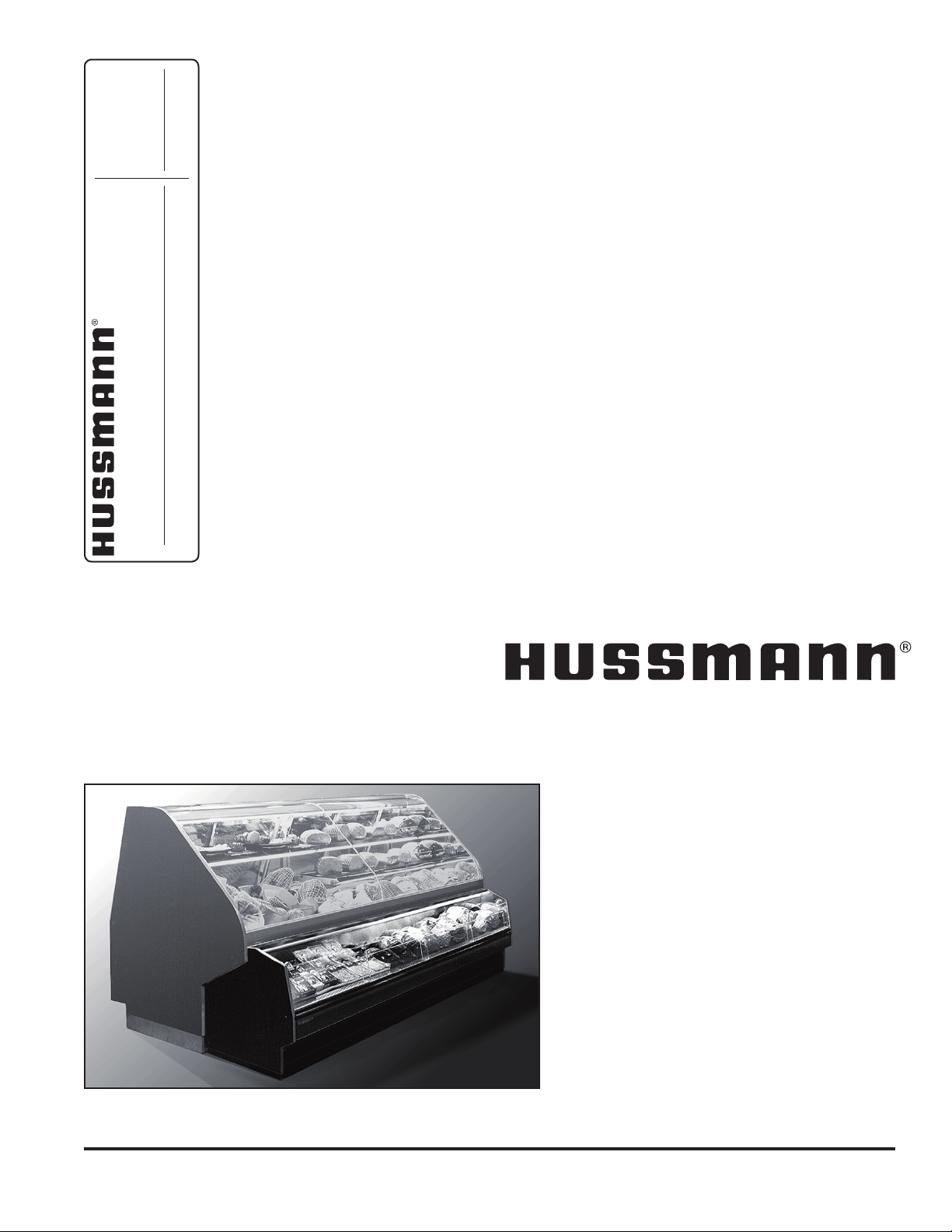
FMSS-L
CASE-FRONT SELF SERVICE
FMSS-L
CASE-FRONT SELF SERVICE REFRIGERATED MERCHANDISER
P/N IGSS-FMSS-L-0708
INSTALLATION & OPERATION GUIDE
Page 2
General Instructions
This equipment is to be installed
to comply with the applicable
NEC, Federal, State , and Local
Plumbing and Construction
Code h a v in g ju r i s diction.
Table of Contents
General Instructions.....................................................2
Cut and Plan Views ......................................................3
Installation .....................................................................3
Location ..................................................................................... 3
Uncrating the Stand ................................................................... 3
Exterior Loading ......................................................................... 3
Setting and Joining .................................................................... 3
Leveling .....................................................................................3
Joint Trim ................................................................................... 4
Bumper Installation Instructions................................................. 5
Plumbing .......................................................................9
Waste Outlet and P-TRAP ......................................................... 9
Installing Condensate Drain....................................................... 9
Refrigeration .................................................................9
Refrigerant Type ........................................................................ 9
Refrigeration Lines ..................................................................... 9
Control Settings - Remote ......................................................... 9
Control Settings - Self Contained .............................................. 9
Access to TX Valves and Drain Lines ........................................ 9
Electronic Expansion Valve (Optional) ....................................... 9
Thermostatic Expansion Valve Location .................................. 10
Measuring the Operating Superheat........................................ 10
T-STAT Location ...................................................................... 10
Ballast Location .......................................................................10
Electrical...................................................................... 11
Wiring Color Code ................................................................... 11
Electrical Circuit Identication .................................................. 11
Electrical Service Receptacles (When Applicable) .................. 11
Field Wiring and Serial Plate Amperage .................................. 11
Ballast Location ....................................................................... 11
User Information ......................................................... 11
Stocking ................................................................................... 11
Important Steps .......................................................................12
Case Cleaning ......................................................................... 12
Cleaning Glass and Mirrors ..................................................... 12
Plexiglass and Acrylic Care ..................................................... 12
Cleaning ................................................................................... 12
Antistatic Coatings ................................................................... 12
Maintenance ................................................................ 13
Replacing Fluorescent Lamps ................................................. 13
Evaporator Fans ...................................................................... 13
Copper Coils ............................................................................ 13
Tips and Troubleshooting ........................................................ 13
Stainless Steel Cleaning and Care .......................................... 13
Electrical Wiring Diagrams ........................................ 14
Wiring Diagrams .........................................................15
Appendices .................................................................22
Appendix A. - Temperature Guidelines .................................... 22
Appendix B. - Application Recommendations .......................... 22
Appendix C. - Field Recommendations ................................... 22
Appendix D. - Recommendations to User ............................... 23
Keep this booklet with the case at all times for future reference.
This Booklet Contains Information on:
FMSS-L, FMSS-L-L-Remote
The FMSS-L, FMSS-L-L is a single-deck, refrigerated,
self-service merchandiser, which offers additional related
display when positioned in front of a “Parent” service case.
The FMSS-L, FMSS-L-L only ts under Hussmann Chino
Style cases.
Shipping Damage
All equipment should be thoroughly examined for shipping
damage before and during unloading.
This equipment has been carefully inspected at our factory
and the carrier has assumed responsibility for safe arrival.
If damaged, either apparent or concealed, claim must be
made to the carrier.
Apparent Loss or Damage
If there is an obvious loss or damage, it must be noted on
the freight bill or express receipt and signed by the carrier’s
agent; otherwise, carrier may refuse claim. The carrier will
supply necessary claim forms.
Concealed Loss or Damage
When loss or damage is not apparent until after equipment
is uncrated, a claim for concealed damage is made. Make
request in writing to carrier for inspection within 15 days,
and retain all packaging. The carrier will supply inspection
report and required claim forms.
Shortages
Check your shipment for any possible shortages of
material. If a shortage should exist and is found to be the
responsibility of Hussmann Chino, notify Hussmann Chino.
If such a shortage involves the carrier, notify the carrier
immediately, and request an inspection. Hussmann Chino
will acknowledge shortages within ten days from receipt
of equipment.
Hussmann Chino Product Control
The serial number and shipping date of all equipment
has been recorded in Hussmann’s les for warranty and
replacement part purposes. All correspondence pertaining
to warranty or parts ordering must include the serial number
of each piece of equipment involved, in order to provide
the customer with the correct parts.
IGSS-FMSS-L-0708
/CHINO
A publication of HUSSMANN® Chino
13770 Ramona Avenue • Chino, California 91710
(909) 628-8942 FAX
(909) 590-4910
(800) 395-9229
2
Page 3
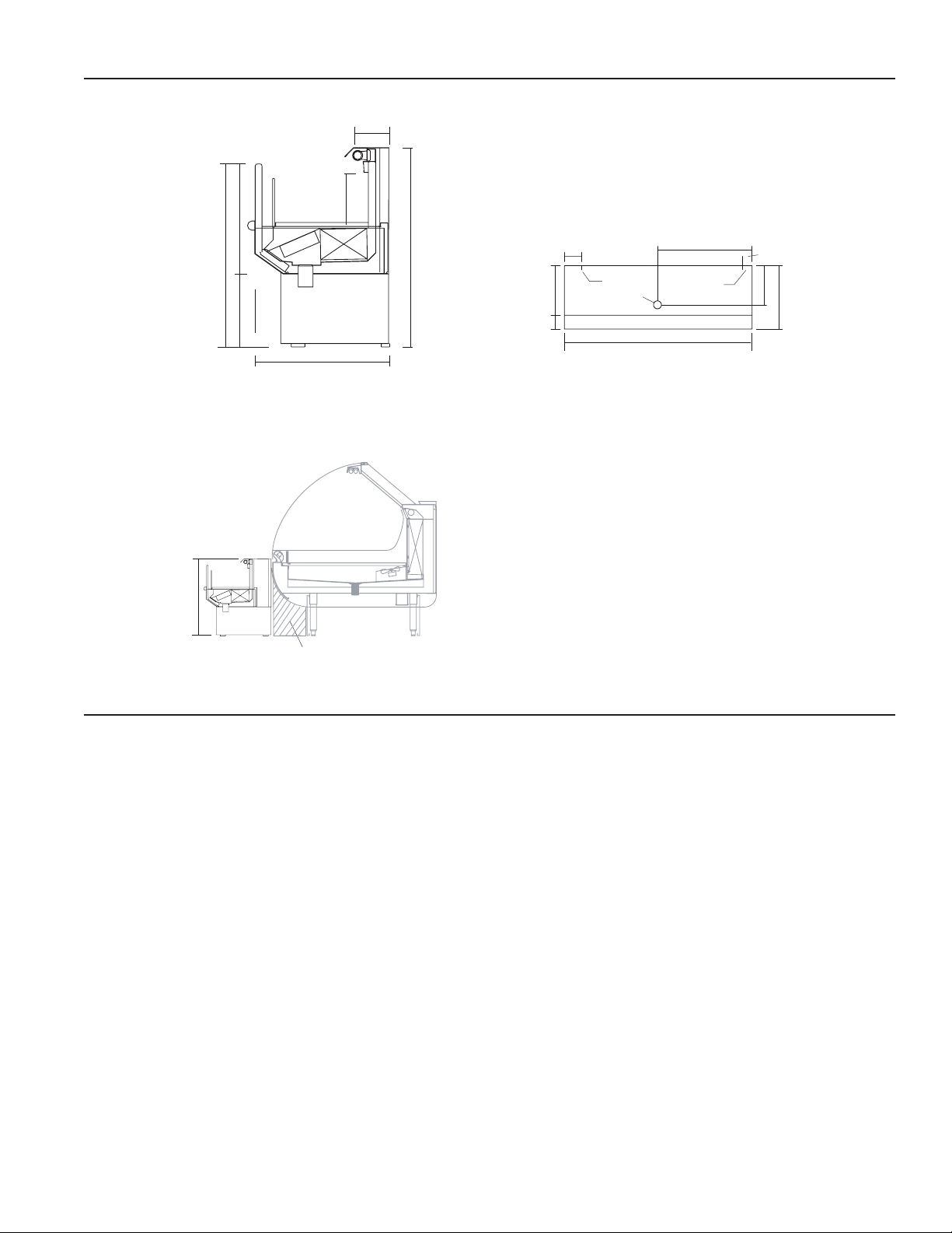
Rev. 0708
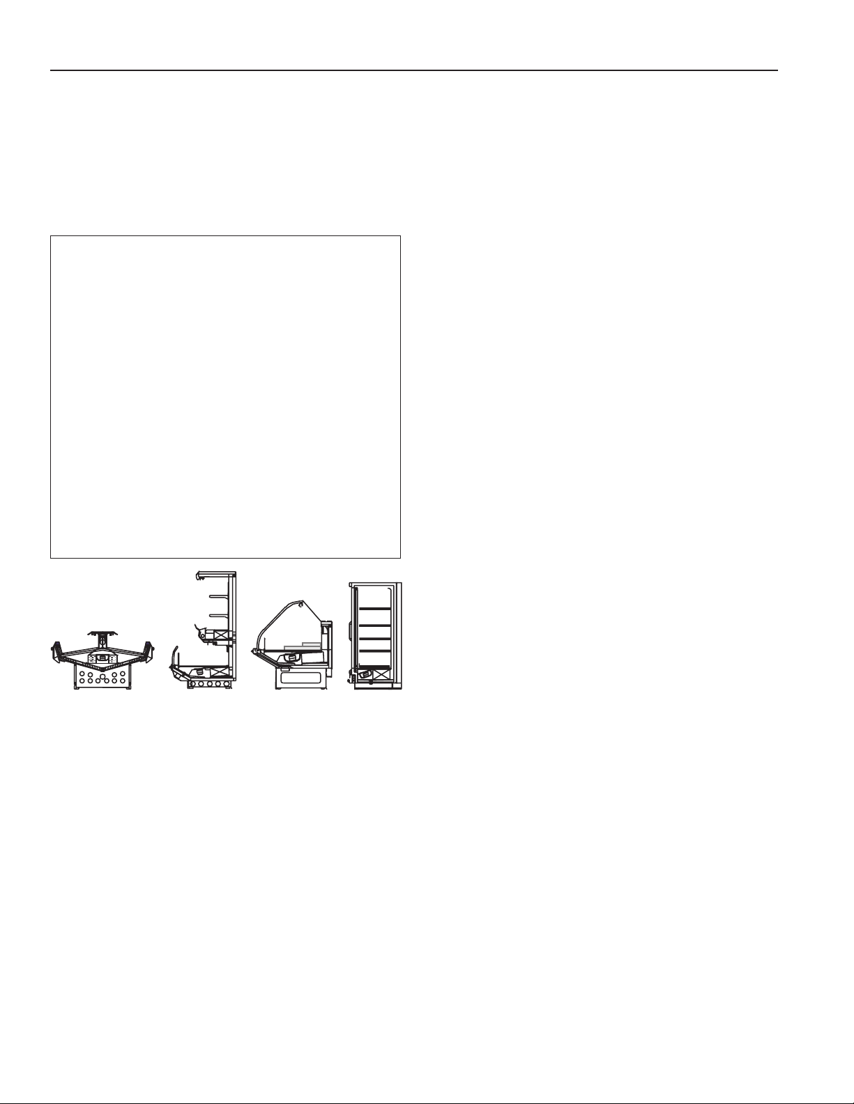
FMSS
Front-Mount Self-Service case. Can be ordered to mount in front
of ANY service case. Base height can be modified to match any
service case bumper height.
ASC
PARENT CASE
FMSS
Height Modified to
match the ASC case
20"
“Field” Close Off
FMSS-L
Self-Service
Remote (Self Contained)
Scale = 1"
16'' Remote
211/2" S.C.
*26
3
/
8
"
*Dimensions
adjust at theses
points to match
service case
height
13
1
/
2
"
113/4"
*10
1
/
2
"
6
1
/
8
"
26'' Remote
28
5
/
8
" S.C.
37/8" Remote
87/8" S.C.
F
a
n
4'
(VARIABLE LENGTHS)
3
1
/
2
"
41/2"
12
1
/
2
"
24"
9
7
/
8
"
16"
(21
1
/
2
"
S.C.)
25/8"
Ref. Drop In
Elec.
Drain
FMSS-L
Plan View
Scale = 1/2"
Cut and Plan Views
Location
The refrigerated merchandisers have been designed
for use only in air conditioned stores where temperature
and humidity are maintained at or below 75°F and 55%
relative humidity. DO NOT allow air conditioning, electric
fans, ovens, open doors or windows (etc.) to create air
currents around the merchandiser, as this will impair its
correct operation.
Product temperature should always be maintained at a
constant and proper temperature. This means that from the
time the product is received, through storage, preparation
and display, the temperature of the product must be
controlled to maximize life of the product.
Uncrating the Stand
Place the xture as close to its permanent position as
possible. Remove the top of the crate. Detach the walls
from each other and remove from the skid. Unbolt the case
from the skid. The xture can now be lifted off the crate
skid. Lift only at base of stand!
Installation
Exterior Loading
These models have not been structurally designed to
support excessive external loading. Do not walk on their
tops; This could cause serious personal injury and damage
to the xture.
Setting and Joining
The case that the FMSS-L connects to (the parent case)
through the rear of the case must be leveled and set prior to
installing the FMSS-L. The sectional construction of these
models enable them to be joined in line - to give the effect of
one continuous display. A joint Trim Kit is supplied with each
case line to cosmetically “mask” the sectional joints.
Leveling
IMPORTANT! IT IS IMPERATIVE THAT CASES BE
LEVELED FROM FRONT TO BACK AND SIDE TO SIDE
PRIOR TO JOINING. A LEVEL CASE IS NECESSARY
TO INSURE PROPER OPERATION, WATER DRAINAGE,
GLASS ALIGNMENT, AND OPERATION OF THE HINGES
SUPPORTING THE GLASS. LEVELING THE CASE
CORRECTLY WILL SOLVE MOST HINGE OPERATION
PROBLEMS.
3
Page 4
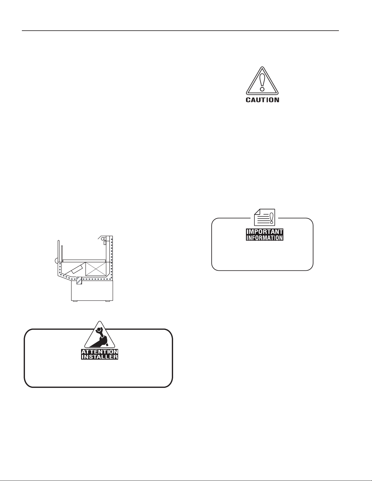
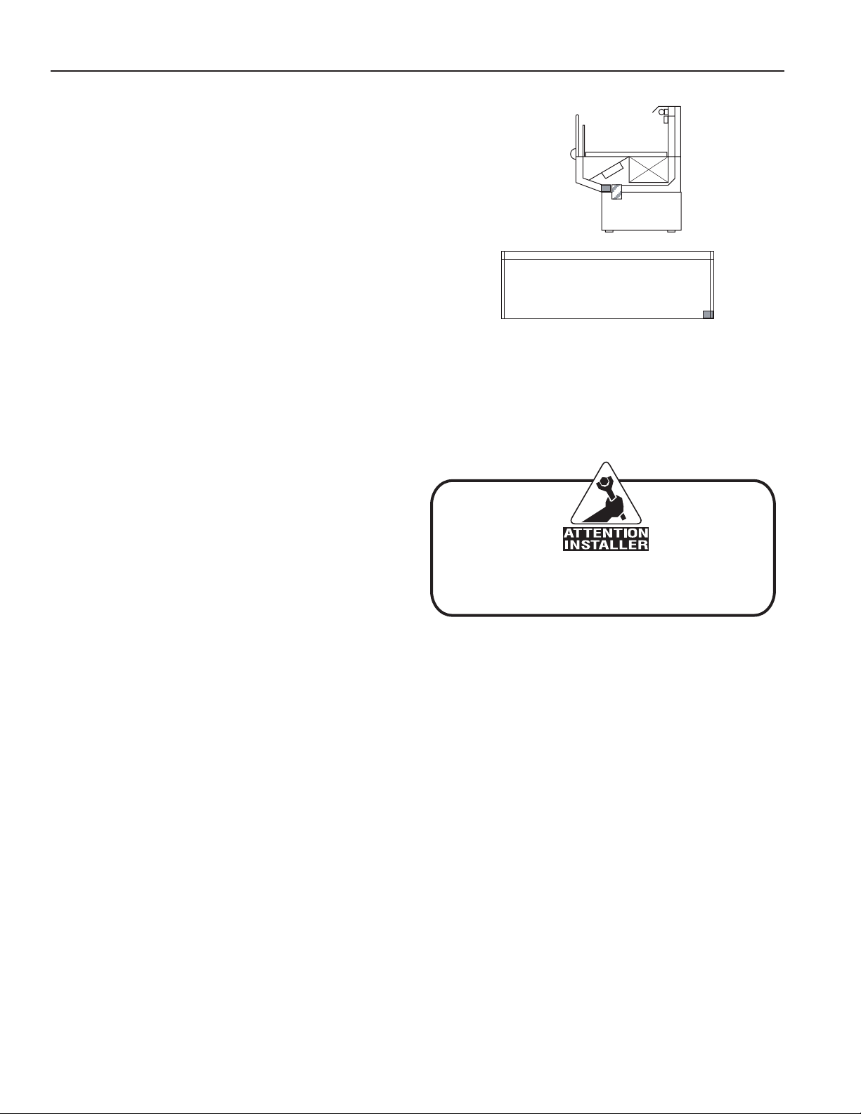
Fig. 2, #1
It is the contractor’s responsibility to install
case(s) according to local construction and
health codes.
Do not use the top bracket on the
rear mullion to pull the cases together.
Proper case-joint sealing is
extremely important to prevent
water leaks!
Installation (Cont'd)
NOTE: A. To avoid removing concrete ooring, begin lineup
leveling from the highest point of the store oor.
B. When wedges are involved in a lineup, set them rst.
All cases were leveled and joined prior to shipment to
insure the closest possible t when cases are joined in
the eld. When joining, use a carpenters level and shim
legs accordingly. Case must be raised correctly, under legs
where support is best, to prevent damage to case.
1. Check level of oor where cases are to be set.
Determine the highest point of the oor; cases will
be set off this point.
2. Level and set the rst case, carefully guiding the
electrical, refrigeration and drain lines through the
parent case. Case must be raised under legs where
support is best to prevent damage to case. Internal
bracing may be removed at this time.
3. Set second case as close as possible to the rst
case carefully guiding its electrical, refrigeration and
drain lines through the parent case, and level case
to the rst using the instructions in step one.
4. Apply masking tape 1/8” in from end of case on inside
and outside rear mullion on both cases to be joined.
5. Apply liberal bead of case joint sealant (butyl) to
(dotted area shown in gure) rst case. Apply heavy
amount to cover entire shaded area.
DO NOT USE PERMAGUM!
IGSS-FMSS-L-0708
6. Slide second case up to rst case snugly. Then level
second case to the rst case so glass front, bumper
and top are ush.
7. To compress silicone at joint, use two Jurgenson
wood clamps. Make sure case is level from front to
back and side to side on inside bulkheads at joint.
8. Attach sections together with the two 3/8” bolts
provided, below the deck at the mullion towards the
rear of the FMSS-L. Remove clamps.
9. Apply bead of silicone to top of bulkheads and slip
on stainless steel bulkhead cap. Also apply silicone
to seam between overhead light tubes.
10. VERY IMPORTANT! Apply liberal amounts of black
silicone to ll all voids down to bulkhead.
11. Use nger to smooth silicone as thin as possible at
masking tape on inside and outside of rear mullion
(apply additional silicone if necessary). Remove
tape applied on line #3.
Joint Trim
After cases have been leveled and joined, and refrigeration,
electrical, and wasted piping work completed, install the
splashguards. Fasten along the top edge, or center, with
#10 X 3/3” sheet metal screws.
DO NOT SEAL JOINT TRIM TO FLOOR!
4
Page 5
Rev. 0708
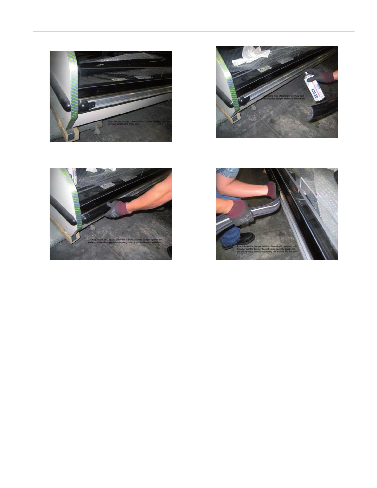
Bumper Installation Instructions
Installation (Cont'd)
Step 1: Make sure the aluminum channel and end caps
are installed.
Step 3: Starting on one end: while inserting the bumper,
push it up against the end cap to prevent
the bumper from shrinking after installation
(when it gets cold).
Step 2: Use silicone lubricant to help the
bumper slide into the channel.
Step 4: As you insert the bumper into the channel with
one hand, pull the bumper toward you with
the other to open the inside lips. Slowly
apply pressure by rolling the bumper into
the track.
5
Page 6
IGSS-FMSS-L-0708
Installation (Cont'd)
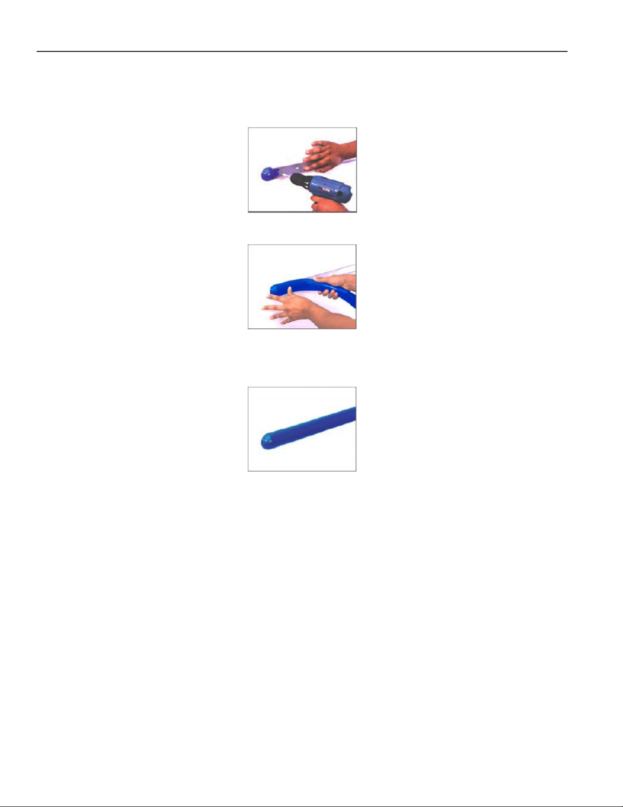
Boston Series 2000
NOTE: Flexible top: Over cut vinyl 1/8" for every 4' section for the exible top to ensure a proper t.
NOTE: Rigid Top: Do not over cut.
1. Attach the base and end/corner cap to the desired surface by inserting #8 pan head screws through the pre-slotted
holes in both the end cap and the base. Insert screws through the two holes of end cap and tighten.
2a. Flexible Top: Butt end of the vinyl top against end/corner cap. While applying pressure, bend back vinyl top so that
vinyl legs are positioned within the base grooves. Roll vinyl top over full length of base, then tap with rubber mallet
to ensure vinyl is securely locked into the base.
2b. Rigid Top: Snap the Rigid Top over the Rigid Base.
3. If necessary wipe clean with any household cleaning product.
Helpful Hints:
● For best results, before cutting, install a scrap piece of base into vinyl top to achieve a clean cut.
● Set the uncoiled flexible vinyl at room temperature 24 hours prior to installation.
● Lubricate the inside of the vinyl with soapy water or silicone before installing.
● Over cut the flexible vinyl and compression fit. Adding the additional materials will compensate for stretching which
occurs during installation.
6
Page 7
Rev. 0708
Installation (Cont'd)
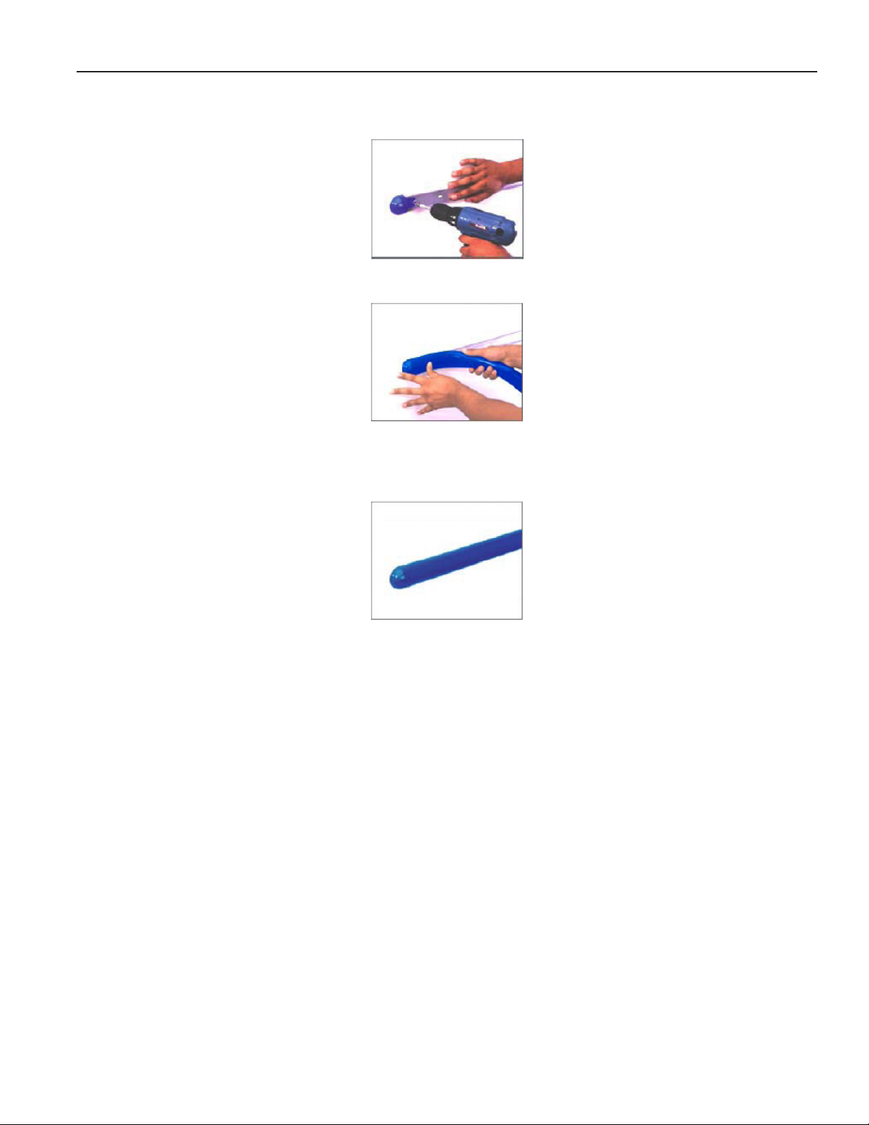
Boston 2000 Eco Series
1. Attach the base and end/corner cap to the desired surface by inserting #8 pan head screws through the pre-slotted
holes in both the end cap and the base. Insert screws through the two holes of end cap and tighten.
2a. Flexible Top: Butt end of the vinyl top against end/corner cap. While applying pressure, bend back vinyl top so that
vinyl legs are positioned within the base grooves. Roll vinyl top over full length of base, then tap with rubber mallet
to ensure vinyl is securely locked into the base.
2b. Rigid Top: Snap the Rigid Top over the Rigid Base.
3. If necessary wipe clean with any household cleaning product.
Helpful Hints:
● For best results, before cutting, install a scrap piece of base into vinyl top to achieve a clean cut.
● Set the uncoiled flexible vinyl at room temperature 24 hours prior to installation.
● Lubricate the inside of the vinyl with soapy water or silicone before installing.
● Over cut the flexible vinyl and compression fit. Adding the additional materials will compensate for stretching which
occurs during installation.
7
Page 8
IGSS-FMSS-L-0708
Installation (Cont'd)
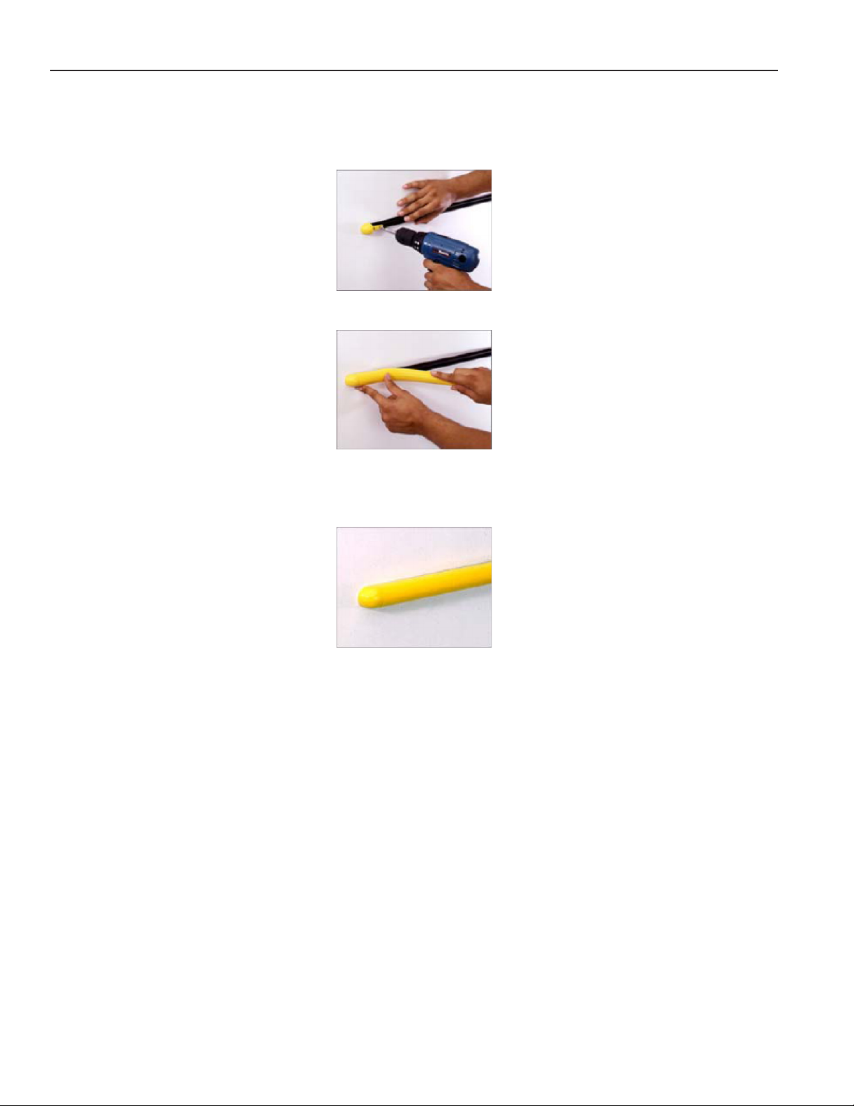
Boston 1000 Series
NOTE: Flexible top: Over cut vinyl 1/8" for every 4' section for the exible top to ensure a proper t.
NOTE: Rigid Top: Do not over cut.
Installation
1. Attach the base and end/corner cap to the desired surface by inserting #8 pan head screws through the pre-slotted
holes in both the end cap and the base. Insert screws through the two holes of end cap and tighten.
2a. Flexible Top: Butt end of the vinyl top against end/corner cap. While applying pressure, bend back vinyl top so that
vinyl legs are positioned within the base grooves. Roll vinyl top over full length of base, then tap with rubber mallet
to ensure vinyl is securely locked into the base.
2b. Rigid Top: Snap the Rigid Top over the Rigid Base.
3. If necessary wipe clean with any household cleaning product.
Helpful Hints:
● For best results, before cutting, install a scrap piece of base into vinyl top to achieve a clean cut.
● Set the uncoiled flexible vinyl at room temperature 24 hours prior to installation.
● Lubricate the inside of the vinyl with soapy water or silicone before installing.
● Over cut the flexible vinyl and compression fit. Adding the additional materials will compensate for stretching which
occurs during installation.
8
Page 9

Rev. 0708
Plumbing
Waste Outlet and P-TRAP
The waste outlet is located at the left hand end of these
xtures allowing drip piping to be run under the xture
lengthwise.
A 1” P-TRAP and threaded adapter are supplied with each
xture. The P-TRAP must be installed to prevent air leakage
and insect entrance into the xture.
Installing Condensate Drain
Poorly or improperly installed condensate drains can
seriously interfere with the operation of this refrigerator, and
result in costly maintenance and product losses. Please
follow the recommendations listed below when installing
condensate drains to insure a proper installation:
1. Never use pipe for condensate drains smaller
than the nominal diameter of the pipe or P-TRAP
supplied with the case.
2. When connecting condensate drains, the P-TRAP
must be used as part of the condensate drain
to prevent air leakage or insect entrance. Store
plumbing system oor drains should be at least 14”
off the center of the case to allow use of the P-TRAP
pipe section. Never use two water seals in series in
any one line. Double P-TRAPS in series will cause a
lock and prevent draining.
Refrigeration
Refrigerant Type
The standard refrigerant will be R-404 unless otherwise
specied on the customer order. Check the serial plate on
the case for information.
Piping for more than one case on a condensing unit is run
underground with either common suction and liquid lines
from the machine room or individual suction and liquid lines
joined together in the machine room.
Refrigeration Lines
Liquid Suction
3/8” O.D. 5/8” O.D.
NOTE: The standard coil is piped at 5/8” (suction); however,
the store tie-in may vary depending on the number of
coils and the draw the case has. Depending on the case
setup, the connecting point in the store may be 5/8”, 7/8”,
or 11/8”. Refer to the particular case you are hooking up.
Refrigerant lines should be sized as shown on the
refrigeration legend furnished by the store.
Install P-TRAPS (oil traps) at the base of all suction line
vertical risers.
Pressure drop can rob the system of capacity. To keep the
pressure drop to a minimum, keep refrigerant line run as
short as possible, using the minimum number of elbows.
Where elbows are required, use long radius elbows only.
For refrigerators with KOOLGAS defrost, suction, and
liquid lines should not contact each other and should
be insulated for a minimum of 30’ from the refrigerator.
Additional insulation for the balance of liquid and
suction lines is recommended and required wherever
condensation and dripping would be objectionable.
3. Always provide as much down hill slope (“fall”) as
possible; 1/8” per foot is the preferred minimum.
PVC pipe, when used, must be supported to
maintain the 1/8” pitch and to prevent warping.
4. Avoid long runs of condensate drains. Long runs
make it impossible to provide the “fall” necessary for
good drainage.
5. Provide a suitable air break between the ood rim of
the oor drain and outlet of condensate drain. 1” is
ideal.
6. Prevent condensate drains from freezing:
a. Do not install condensate drains in contact with
non-insulated suction lines. Suction lines should
be insulated with a non-absorbent insulation
material such as Armstrong’s Armaex.
b. Where condensate drains are located in dead
air spaces (between refrigerators or between a
refrigerator and a wall), provide means to prevent
freezing. The water seal should be insulated to
prevent condensation.
Control Settings - Remote
See FMSS-L technical data sheet for the appropriate
settings for your merchandiser. Maintain these parameters
to achieve near constant product temperatures. Product
temperature should be measured rst thing in the morning,
after having been refrigerated overnight. Defrost times
should be as directed in the FMSS-L technical data sheet.
The number of defrosts per day should never change.
The duration of the defrost cycle may be adjusted to meet
conditions present at your location.
Control Settings - Self Contained
On Self Contained cases all functions, defrost, fans,
temperature are controlled by Pagon ERC-2 controller. See
case specs for proper temperature and defrost settings.
Access to TX Valves and Drain Lines
Mechanical - Remove product from end of case. Remove
product racks. Remove refrigeration and drain access
panels (labeled). TX valve (mechanical only) and drain are
located under each access panel at end of the case.
Electronic - The Electronic Expansion valve master and
slave cylinder(s) are located within the electrical access
panel(s).
Electronic Expansion Valve (Optional)
A wide variety of electronic expansion valves and case
controllers can be utilized. Please refer to EEV and
controller manufacturers information sheet. Sensors for
electronic expansion valves will be installed on the coil inlet,
coil outlet, and in the discharge air. (Some supermarkets
require a 4th sensor in the return air). Case controllers will
be located in the electrical raceway or under the case.
9
Page 10
Front of Case
It is the contractor’s responsibility to install
case(s) according to local construction and
health codes.
Refrigeration (Cont'd)
Thermostatic Expansion Valve Location
This device is located on the same side as the refrigeration
stub. An Alco balanced port expansion valve model
is furnished as standard equipment, unless otherwise
specied by customer.
Expansion Valve Adjustment
Expansion valves must be adjusted to fully feed the
evaporator. Before attempting any adjustments, make
sure the evaporator is either clear or very lightly covered
with frost, and that the xture is within 10°F of its expected
operating temperature.
Measuring the Operating Superheat
1. Determine the suction pressure with an accurate
pressure gauge at the evaporator outlet.
2. From a refrigerant pressure temperature chart,
determine the saturation temperature at the
observed suction pressure.
3. Measure the temperature of the suction gas at the
thermostatic remote bulb location.
4. Subtract the saturation temperature obtained in step
No. 2 from the temperature measured in step No. 3.
5. The difference is superheat.
6. Set the superheat for 5°F - 7°F.
T-STAT Location
Thermostats are located within the electrical raceway.
The raceway location is dependent on the style of the
front panel and whether the case is going to be pushed
up against a wall.
IGSS-FMSS-L-0708
Ballast Location
Ballast and T-stat are located in the front right hand area
of the case, viewed from customer angle.
In all cases, the thermostat is located on the same side of
the case. If you are looking at the case from the front, it is
the right-hand side. If you are looking at the case from the
back, it is the left-hand side.
10
Page 11

Rev. 0708
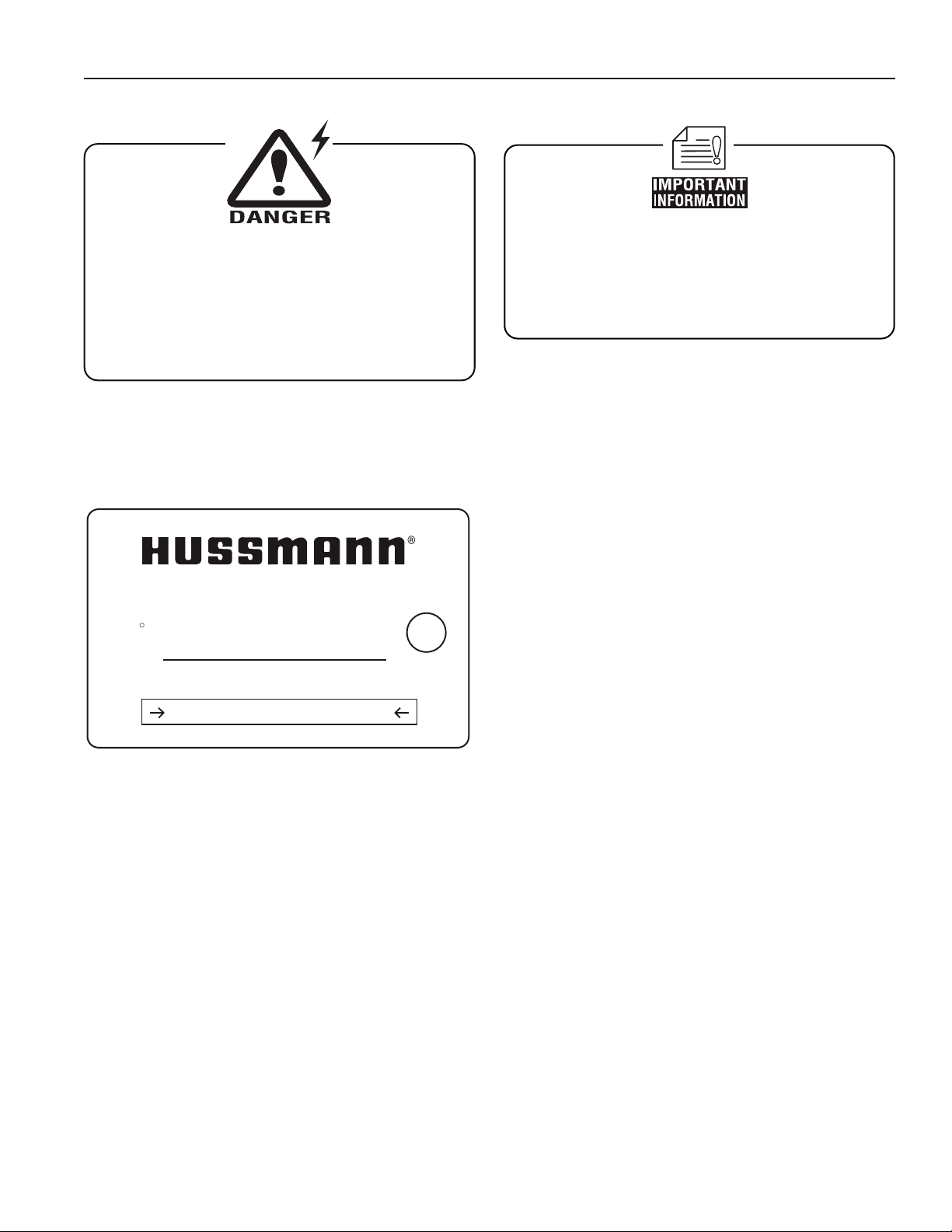
BEFORE SERVICING
ALWAYS DISCONNECT ELECTRICAL
POWER AT THE MAIN DISCONNECT
WHEN SERVICING OR REPLACING ANY
ELECTRICAL COMPONENT.
This includes (but not limited to) Fans, Heaters
Thermostats, and Lights.
Electrical
Wiring Color Code
CASE MUST BE GROUNDED
NOTE: Refer to label afxed to case to determine the actual
conguration as checked in the “TYPE INSTALLED”
boxes.
Electrical Circuit Identication
Standard lighting for all models will be full length uorescent
lamps located on the front of the parent case. The switch
controlling the lights is located on the parent case.
Electrical Service Receptacles (When Applicable)
The receptacles located on the exterior of the merchandiser
are intended for scales and lighted displays. They are not
intended nor suitable for large motors or other external
appliances.
User Information
Field Wiring and Serial Plate Amperage
Field Wiring must be sized for component amperes printed
on the serial plate. Actual ampere draw may be less than
specied. Field wiring from the refrigeration control panel to
the merchandisers is required for refrigeration thermostats.
Case amperes are listed on the wiring diagram, but always
check the serial plate.
Ballast Location
Ballasts are located within the access panel that runs the
length of the rear of the case. Refer to diagram on page 6.
Stocking
Improper temperature and lighting will cause serious
product loss. Discoloration, dehydration and spoilage
can be controlled with proper use of the equipment and
handling of product. Product temperature should always
be maintained at a constant and proper temperature.
This means that from the time the product is received,
through storage, preparation and display, the temperature
of the product must be controlled to maximize life of the
product. Hussmann cases were not designed to “heat up”
or “cool down” product - but rather to maintain an item’s
proper temperature for maximum shelf life. To achieve the
protection required always:
1. Minimize processing time to avoid damaging
temperature rise to the product. Product should be
at proper temperature.
2. Keep the air in and around the case area free
of foreign gasses and fumes or food will rapidly
deteriorate.
3. Maintain the display merchandisers temperature
controls as outlined in the refrigerator section of this
manual.
4. Do not place any product into these refrigerators
until all controls have been adjusted and they
are operating at the proper temperature. Allow
merchandiser to operate a minimum of 6 hours
before stocking with any product.
5. When stocking, never allow the product to extend
beyond the recommended load limit. Air discharge
and return air ow must be unobstructed at all
times to provide proper refrigeration.
6. There are vents located at the base of the front of the
glass, just above the front rail. These vents supply a
continuous, gentle ow of air across the front glass
which inhibits condensation. Do not place any
signs or other restrictive objects on the front of
the refrigerator that will block these vents.
7. Keep the service doors closed (when applicable).
Refrigeration performance will be seriously affected
if left open for a prolonged period of time.
11
Page 12
CLEANING PRECAUTIONS
When cleaning:
• Do not use high pressure water hoses
• Do not introduce water faster then waste outlet can drain
• NEVER INTRODUCE WATER ON SELF CONTAINED UNIT
WITH AN EVPORATOR PAN
• NEVER USE A CLEANING OR SANITIZING SOLUTION
THAT HAS AN OIL BASE (these will dissolve the butyl
sealants) or an AMMONA BASE (this will corrode the
copper components of the case)
• TO PRESERVE THE ATTRACTIVE FINISH:
• DO USE WATER AND A MILD DETERGENT FOR THE
EXTERIOR ONLY
• DO NOT USE A CHLORANITED CLAENER ON ANY
SURFACE
• DO NOT USE ABRASIVES OR STEEL WOOL SCOURING
PADS (these will mar the finish)
CAUTIO
N
User Information (Cont'd)
IGSS-FMSS-L-0708
8. Avoid the use of supplemental ood or spot lighting.
Display light intensity has been designed for
maximum visibility and product life at the factory.
The use of higher output uorescent lamps (H.O.
and V.H.O.), will shorten the shelf life of the product.
Important Steps
1. Do not set temperature too cold, as this causes
product dehydration. Product Temperature: 10°F!.
Set thermostat to cut in at -5°F discharge air.
2. Temperature control should be by means of a
T-STAT and Suction Stop Solenoid at each case. Do
not use EPR valves, Liquid Line Solenoids or
electronic control devices of any kind, as these
allow temperature swings causing dehydration and
excessive energy consumption.
Case Cleaning
Long life and satisfactory performance of any equipment
are dependent upon the care given to it. To insure long
life, proper sanitation and minimum maintenance costs,
the refrigerator should be thoroughly cleaned frequently.
SHUT OFF FAN DURING CLEANING PROCESS. It can be
unplugged within the case, or shut off case at the source.
The interior bottom may be cleaned with any domestic soap
or detergent based cleaners. Sanitizing solutions will not
harm the interior bottom, however, these solutions should
always be used according to the manufacturer’s directions.
It is essential to establish and regulate cleaning procedures.
This will minimize bacteria causing discoloration which
leads to degraded product appearance and signicantly
shortening product shelf life.
Soap and hot water are not enough to kill this bacteria. A
sanitizing solution must be included with each cleaning
process to eliminate this bacteria.
1. Scrub thoroughly, cleaning all surfaces, with soap
and hot water.
2. Rinse with hot water, but do not ood.
3. Apply the sanitizing solution according to
Hussmann’s directions.
4. Rinse thoroughly.
5. Dry completely before resuming operation.
Cleaning Glass and Mirrors
Only use a soft cloth and water for cleaning any glass
or mirrored components. Be sure to rinse and/or dry
completely.
Never use hot water on cold glass surfaces! It may
shatter and cause serious injury! Allow glass surfaces
to warm rst.
Plexiglass and Acrylic Care
Improper cleaning not only accelerates the cleaning cycle
but also degrades the quality of this surface. Normal daily
bufng motions can generate static cling attracting dust to
the surface. Incorrect cleaning agents or cleaning cloths
can cause micro scratching of the surface, causing the
plastic to haze over time.
Cleaning
Hussmann recommends using a clean damp chamois, or a
paper towel marketed as dust and abrasive free with 210®
Plastic Cleaner and Polish available by calling Sumner
Labs at 1-800-542-8656. Hard, rough cloths or paper towels
will scratch the acrylic and should not be used.
Antistatic Coatings
The 210® has proven to be very effective in not only
cleaning and polishing the Plexiglass surface, but also
providing anti-static and anti-fog capabilities. This product
also seals pores and provides a protective coating.
12
Page 13
Rev. 0708
BEFORE SERVICING
ALWAYS DISCONNECT ELECTRICAL
POWER AT THE MAIN DISCONNECT
WHEN SERVICING OR REPLACING ANY
ELECTRICAL COMPONENT.
This includes (but not limited to) Fans, Heaters
Thermostats, and Lights.
ENCAPSULITE
SHATTERPROOF COATING - SA 10645
Complies with FDA USDA
& OSHA Regulations
for replacement call:
1-800-395-9229
Turn switch off then on after replacing bulb
NSF
U
R
R
FOR PROMPT SERVICE
When contacting the factory,
be sure to have the Case Model and Serial
Number handy. This information is on a plate
located on the case itself.
Replacing Fluorescent Lamps
Fluorescent lamps are furnished with moisture resistant
lamp holders, shields and end caps. Whenever a orescent
lamp is replaced, be certain to reinstall the lamp shield and
end caps over the lamp. The lamps supplied are single
slim-line or bi-pin type with or without starters.
Evaporator Fans
The evaporator fans are located at the center front of these
merchandisers directly beneath the display pans.
Copper Coils
The copper coils used in Hussmann merchandisers may
be repaired in the eld. Materials are available from local
refrigeration wholesalers.
Hussmann recommends using #15 Sil-Fos for repairs.
Tips and Troubleshooting
Before calling for service, check the following:
1. Check electrical power supply to the equipment for
connection.
2. Check xture loading. Overstocking case will affect
its proper operation.
3. If frost is collecting on xture and/or product, check
that Humidity Control is working properly, and that
no outside doors or windows are open - allowing
moisture to enter store.
Maintenance
Stainless Steel Cleaning and Care
There are three basic things, which can break down your
stainless steel’s passivity layer and allow corrosion.
1. Mechanical Abrasion
Mechanical Abrasion means those things that
will scratch the steels surface. Steel Pads, wire
Brushes, and Scrapers are prime examples.
2. Water
Water comes out of our tap in varying degrees of
hardness. Depending on what part of the country
you live in, you may have hard or soft water. Hard
water may leave spots. Also, when heated, hard
water leaves deposits behind that if left to sit, will
break down the passive layer and rust your stainless
steel. Other deposits from food preparation and
service must be properly removed.
3. Chlorides
Chlorides are found nearly everywhere. They
are in water, food and table salt. One of the worst
perpetrators of chlorides can come from household
and industrial cleaners.
Don’t Despair! Here are a few steps that can help prevent
stainless steel rust.
1. Use the Proper Tools
When cleaning your stainless steel products, take
care to use non-abrasive tools. Soft Clothes and
plastic scouring pads will NOT harm the steel’s
passive layer. Stainless steel pads can also be
used but the scrubbing motion must be in the same
direction of the manufacturer’s polishing marks.
2. Clean With the Polish Lines
Some stainless steels come with visible polishing
lines or “grain”. When visible lines are present, you
should ALWAYS scrub in a motion that is parallel to
them. When the grain cannot be seen, play it safe
and use a soft cloth or plastic scouring pad.
13
Page 14

IGSS-FMSS-L-0708
3. Use Alkaline, Alkaline Chlorinated or
Non-chloride Containing Cleaners
While many traditional cleaners are loaded
with chlorides, the industry is providing an ever
increasing choice of non-chloride cleaners. If you
are not sure of your cleaner’s chloride content
contact your cleaner supplier. If they tell you that
your present cleaner contains chlorides, ask for
an alternative. Also, avoid cleaners containing
quaternary salts as they also can attack stainless
steel & cause pitting and rusting.
4. Treat your Water
Though this is not always practical, softening hard
water can do much to reduce deposits. There
are certain lters that can be installed to remove
distasteful and corrosive elements. Salts in a
properly maintained water softener are your friends.
If you are not sure of the proper water treatment, call
a treatment specialist.
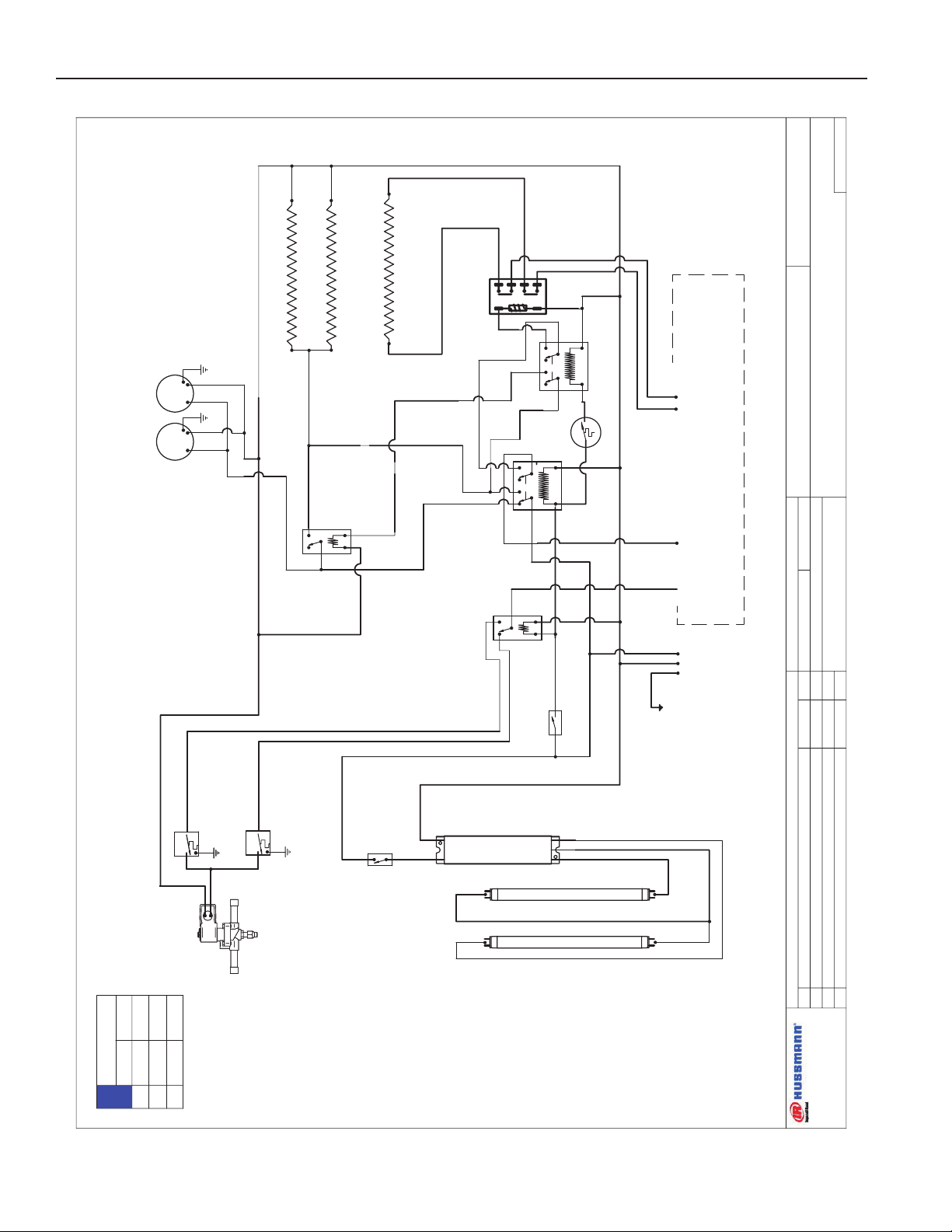
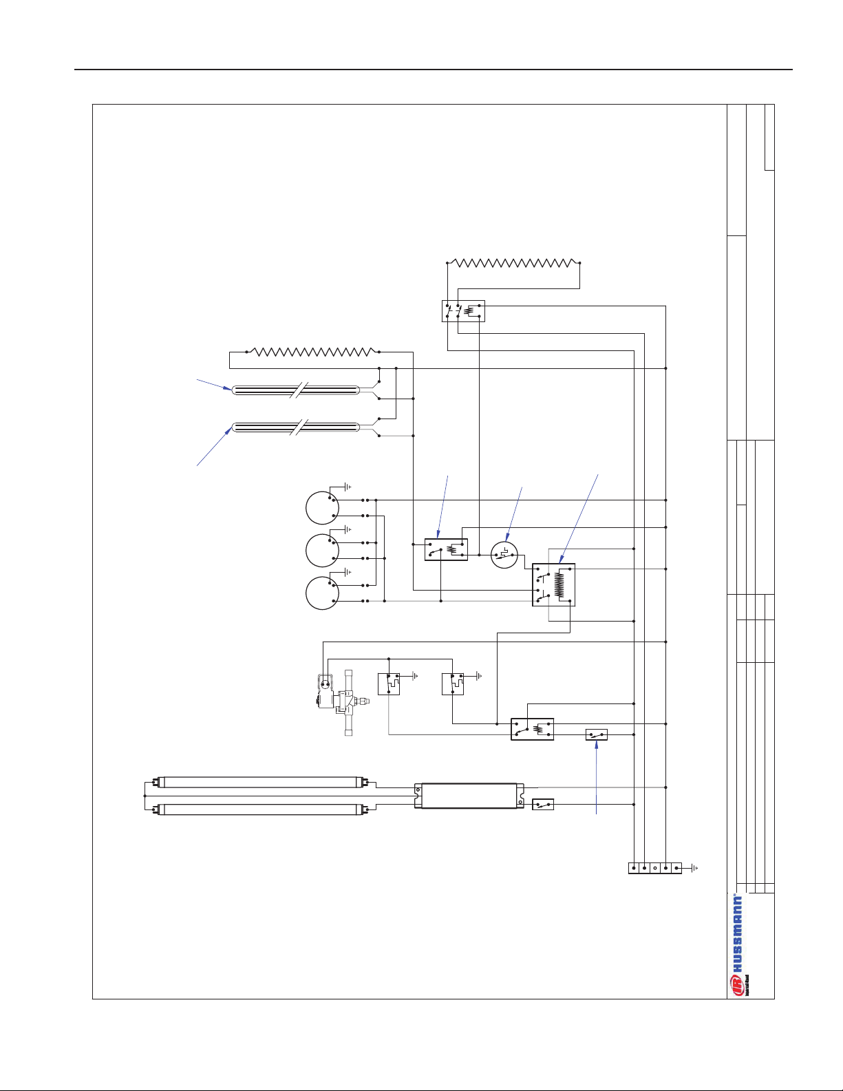
Electrical Wiring Diagrams
5. Keep your Food Equipment Clean
Use alkaline, alkaline chlorinated or non-chlorinated
cleaners at recommended strength. Clean
frequently to avoid build-up of hard, stubborn stains.
If you boil water in your stainless steel equipment,
remember the single most likely cause of damage is
chlorides in the water. Heating cleaners that contain
chlorides has a similar effect.
6. RINSE, RINSE, RINSE
If chlorinated cleaners are used you must rinse,
rinse, rinse and wipe dry immediately. The sooner
you wipe off standing water, especially when sit
contains cleaning agents, the better. After wiping the
equipment down, allow it to air dry for the oxygen
helps maintain the stainless steel’s passivity lm.
7. Never Use Hydrochloric Acid (Muriatic Acid) on
Stainless Steel
8. Regularly Restore/Passivate Stainless Steel
3’
W1400007
Low / Medium Temp
FMSS-L 4’ REM DUAL TEMP 4’
FMSS-L 8’ REM DUAL TEMP 8’
10’
11’
12’
8’
W1400009
W1400015
W1400012
W1400016
W1400017
W1400005
14
Page 15

Rev. 0708
DATE:
PROJECT TITLE:
DRAWING #:
DRAWN BY:
PRODUCTION ORDER #:
DRAWING TITLE:
DATE:
Hussmann Corporation, Int'l.
13770 Ramona Avenue
Chino, CA. 91710
(909)-590-4910 Lic.#: 644406
REVISIONS:
#: DESCRIPTION:
CHECKED BY:
BY:
FILE LOCATION:
M. KIMURA
PAGE OF1
1
05/12/04
A (2) 125-01-3234A was (1) 125-01-0493 9/5/07 JR
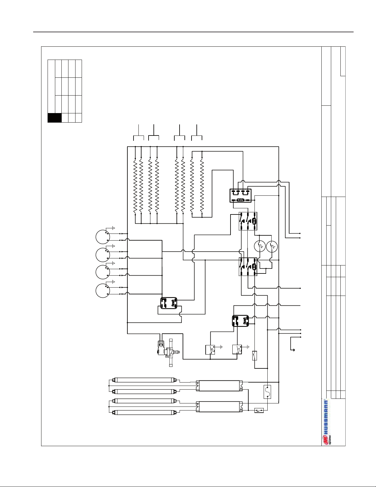
FMSS-L/M CASES
W1400007
3' CASE - ELECTRIC DEFROST
4
5
6 3
2
1
6
0
824
1
1
3
5
2
4
1
3
5
2
4
RELAY MARS 90341
COIL:~115V
PN:125-01-1343
RELAY OMRON
G7L-2A-TUBJ-CB-AC24D
125-01-3182A
RELAY MARS
90249Q
225-01-2045
BALLAST 125-01-3266
FULHAM LH3-120-L
G N L
L1 L2
~ 120VAC
60Hz.
~208/~240VAC - 60Hz.
D
Defrost
120 V
C
Refrig
120 V
KLIXON™ THERMODISK
20420L15-913-302
L20-1.5
00003382
RELAY MARS
90249Q
225-01-2045
4
5
6 3
2
1
TEMPERATURE
TOGGLE
SWITCH
LIGHT
TOGGLE
SWITCH
MEDIUM TEMP
THERMOSTAT
A19AGD-21
225-01-0707
LOW TEMP
THERMOSTAT
A19AGD-21
225-01-0707
EVAP FAN MOTORS
(1) 3 1/2" AXIAL FANS
EBM-PAPST 3306
00001212A
0.12 AMPS @ 120V
DEFROST HEATERS (18")
(2) 660W 2.75A @ 240VAC
125-01-3234A
CAP UNUSED RED LEAD
M
TO DEFROST CONTROL PANEL
CONDUCTIVE GLASS HEATER
20 W/FT @ 120VAC (60W 0.5A)
ANTI SWEAT HEATER
10 W/FT @ 120VAC (30W .25A)
125-01-0767
SOLENOID VALVE
225-01-3206
CANOPY LIGHTING
FP21T5/830
125-03-1128
BLK # 14
WHT # 14
GRN # 14
BLK # 14
BLK # 14
BLK # 14
RED # 14
LIGHT CIRCUIT= 0.2A 21W
CIRCUIT #1
L1
L2
LOADING
208 V 240 V
5.7
4.8
6.6
5.5
Wiring Diagrams
15
Page 16

DATE:
PROJECT TITLE:
DRAWING #:
DRAWN BY:
PRODUCTION ORDER #:
DRAWING TITLE:
DATE:
Hussmann Corporation, Int'l.
13770 Ramona Avenue
Chino, CA. 91710
(909)-590-4910 Lic.#: 644406
REVISIONS:
#: DESCRIPTION:
CHECKED BY:
BY:
FILE LOCATION:
D.QUAN
PAGE OF1 1
03/17/05
123
FMSS-L/M CASES
W1400009
8' CASE - ELECTRIC DEFROST-DUAL TEMP
4
5
6 3
2
1
6028 4
1
135 2
4
135 2
4
RELAY MARS 90341
COIL:~115V
PN:125-01-1343
RELAY OMRON
G7L-2A-TUBJ-CB-AC24D
125-01-3182A
RELAY MARS
90249Q
225-01-2045
M
G N L
L1 L2
~ 115VAC
50/60Hz.
~208/~240VAC - 1Ø - 50/60Hz.
D
Defrost
ON
115 V
C
Case
ON
115 V
RELAY MARS
90249Q
225-01-2045
4
5
6 3
2
1
TEMPERATURE
TOGGLE SWITCH
MEDIUM TEMP
THERMOSTAT
A19AGD-21 225-01-0707
SOLENOID VALVE
LOW TEMP
THERMOSTAT
A19AGD-21
225-01-0707
SOLENOID VALVE
DEFROST FINNED HEATERS
(1) 2250W @ 240VAC
00000262
LIGHT SWITCH
TOGGLE
125-01-0329
CANOPY LIGHTING
(2) FP28T5/830
EVAPORATOR MOTORS
EBM-PAPST™ MODEL 3306
(3) 3½" AXIAL / 0.12A @ 115V
00001212A
CONDUCTIVE GLASS
HEATER
0.64A @ ~115 VAC
150-01-7796
BALLAST 125-01-3266
FULHAM LH3-120-L
(2) 125-01-0767
RAYCHEM
10BUT-CR-10W
ANTI-SWEAT HEATER
(CASE LENGTH)
MM
RELAY MARS 90341
COIL:~115V
PN:125-01-1343
KLIXON™ THERMODISK
20420L15-913-302
L20-1.5
00003382
POWER:
~208/240 VAC - 1Ø - 50/60Hz. - 4W
NOTE:
CASE MUST BE GROUNDED
FM S S - L/ M - 8
R EM O TE
TOTAL AM PS = 3.3 @ 240 VAC
ELE C T R IC A L
EVAP FA NS 1 @
0.12 A MPS 115V
GLASS HEATERS
SOLENOID VA LV E
R EF R I GE R A T I ON
3 DEFROSTS DAILY
@ 26 M IN (ELECTRIC)
EVAP TEM P
-20 °F
CASE TEMP
-5°
115 V
L1 4.37L2L3
~
~
208 V
8.83
8.83
~
240 V
9.33
9.33
~
LOADING
NOTE:
CASE MUST BE GROUNDED
IGSS-FMSS-L-0708
Wiring Diagrams (Cont'd)
16
Page 17

Rev. 0708
DATE:
PROJECT TITLE:
DRAWING #:
DRAWN BY:
PRODUCTION ORDER #:
DRAWING TITLE:
DATE:
Hussmann Corporation, Int'l.
13770 Ramona Avenue
Chino, CA. 91710
(909)-590-4910 Lic.#: 644406
REVISIONS:
#: DESCRIPTION:
CHECKED BY:
BY:
FILE LOCATION:
D.QUAN
PAGE OF1 1
02/24/06
123
FMSS-L/M CASES
W1400015
10' CASE - ELECTRIC DEFROST-DUAL TEMP
4
5
6 3
2
1
6028 4
1
135
2
4
1
3
5
2
4
RELAY MARS 90341
COIL:~115V
PN:125-01-1343
RELAY OMRON
G7L-2A-TUBJ-CB-AC24D
125-01-3182A
RELAY MARS
90249Q
225-01-2045
M
G N L
L1 L2
~ 115VAC
50/60Hz.
~208/~240VAC - 1Ø - 50/60Hz.
D
Defrost
ON
115 V
C
Case
ON
115 V
RELAY MARS
90249Q
225-01-2045
4
5
6 3
2
1
TEMPERATURE TOGGLE
SWITCH
125-01-0329
MEDIUM TEMP
THERMOSTAT
A19AGD-21 225-01-0707
LOW TEMP
THERMOSTAT
A19AGD-21
225-01-0707
SOLENOID VALVE
225-01-3206
DEFROST HEATERS (FINNED HEATER)
(1) 00000259 (1200W 36" 240VAC )
(1) 00000258 (1200W 36" 240V AC)
LIGHT SWITCH
TOGGLE
125-01-0329
EVAPORATOR MOTORS
EBM-PAPST™ MODEL 3306
(4) 3½" AXIAL / 0.12A @ 115V
00001212A
CONDUCTIVE GLASS
HEATER
0.64A @ ~115 VAC
(1) 150-01-5421
(1) 150-01-5421
(2) 125-01-0767
RAYCHEM
10BUT-CR-10W
ANTI-SWEAT HEATER
(CASE LENGTH)
10W/FT
125-01-0767
M
M
RELAY MARS 90341
COIL:~115V
PN:125-01-1343
KLIXON™ THERMODISK
20420L15-913-302
L20-1.5
(2) 00003382
M
CANOPY LIGHTING
(2) FP35/T5/830
60"
125-03-1134
CAP OFF WIRE
NOTE: THIS A SPECIAL WIRING DIAGRAM FOR 5FT & 5FT TOGETHER
CAP OFF WIRE
15 AMP FUSE
125-01-3282
FUSE HOLDER
125-01-3283
BALLAST 125-01-3265
FULHAM LH2-120-L
BALLAST 125-01-3265
FULHAM LH2-120-L
POWER:
~208/240 VAC - 1Ø - 50/60Hz.
NOTE:
CASE MUST BE GROUNDED
115 V
L1 4.8
L2
L3
~
~
208 V
8.5
8.5
~
240 V
10.0
10.0
~
NOTE:
CASE MUST BE GROUNDED
LOADING
Wiring Diagrams (Cont'd)
17
Page 18

IGSS-FMSS-L-0708
DATE:
PROJECT TITLE:
DRAWING #:
DRAWN BY:
PRODUCTION ORDER #:
DRAWING TITLE:
DATE:
Hussmann Corporation, Int'l.
13770 Ramona Avenue
Chino, CA. 91710
(909)-590-4910 Lic.#: 644406
REVISIONS:
#: DESCRIPTION:
CHECKED BY:
BY:
FILE LOCATION:
D.QUAN
PAGE OF1 1
09/07/04
123
FMSS-L/M CASES
W1400012
11' CASE - ELECTRIC DEFROST-DUAL TEMP
4
5
6 3
2
1
6028 4
1
1
3
5
2
4
1
3
5
2
4
RELAY MARS 90341
COIL:~115V
PN:125-01-1343
RELAY OMRON
G7L-2A-TUBJ-CB-AC24D
125-01-3182A
RELAY MARS
90249Q
225-01-2045
M
G N L
L1 L2
~ 115VAC
50/60Hz.
~208/~240VAC - 1Ø - 50/60Hz.
D
Defrost
ON
115 V
C
Case
ON
115 V
RELAY MARS
90249Q
225-01-2045
4
5
6 3
2
1
TEMPERATURE
TOGGLE SWITCH
MEDIUM TEMP
THERMOSTAT
A19AGD-21 225-01-0707
SOLENOID VALVE
LOW TEMP
THERMOSTAT
A19AGD-21
225-01-0707
SOLENOID VALVE
DEFROST HEATERS (FINNED HEATER)
(1) 00000259 (1200W 36" 240VAC)
(1) 00000260 (2000W 54" 240VAC)
LIGHT SWITCH
TOGGLE
125-01-0329
CANOPY LIGHTING
(2) FP21/T5/830
125-03-1128
EVAPORATOR MOTORS
EBM-PAPST™ MODEL 3306
(4) 3½" AXIAL / 0.12A @ 115V
00001212A
CONDUCTIVE GLASS
HEATER
0.64A @ ~115 VAC
(1) 150-01-7797
(1) 150-01-5421
(2) 125-01-0767
RAYCHEM
10BUT-CR-10W
ANTI-SWEAT HEATER
(CASE LENGTH)
10W/FT
125-01-0767
MM
RELAY MARS 90341
COIL:~115V
PN:125-01-1343
KLIXON™ THERMODISK
20420L15-913-302
L20-1.5
(2) 00003382
M
CANOPY LIGHTING
(1) FP35/T5/830
125-03-1134
CAP OFF WIRE
NOTE: THIS A SPECIAL WIRING DIAGRAM FOR 6FT & 5FT TOGETHER
BALLAST 125-01-3267
FULHAM LH4-120-L
BALLAST 125-01-3265
FULHAM LH2-120-L
POWER:
~208/240 VAC - 1Ø - 50/60Hz.
NOTE:
CASE MUST BE GROUNDED
115 V
L1 3.6
L2
L3
~
~
208 V
11.3
11.3
~
240 V
13.3
13.3
~
NOTE:
CASE MUST BE GROUNDED
LOADING
Wiring Diagrams (Cont'd)
18
Page 19
Rev. 0708
DATE:
PROJECT TITLE:
DRAWING #:
DRAWN BY:
PRODUCTION ORDER #:
DRAWING TITLE:
DATE:
Hussmann Corporation, Int'l.
13770 Ramona Avenue
Chino, CA. 91710
(909)-590-4910 Lic.#: 644406
REVISIONS:
#: DESCRIPTION:
CHECKED BY:
BY:
FILE LOCATION:
D.QUAN
PAGE OF1 1
05/16/06
123
FMSS-L/M CASES
W1400016
12' CASE - ELECTRIC DEFROST-DUAL TEMP
4
5
6 3
2
1
6028 4
1
135
2
4
1
3
5
2
4
RELAY MARS 90341
COIL:~115V
PN:125-01-1343
RELAY OMRON
G7L-2A-TUBJ-CB-AC24D
125-01-3182A
RELAY MARS
90249Q
225-01-2045
M
G N L
L1 L2
~ 115VAC
50/60Hz.
~208/~240VAC - 1Ø - 50/60Hz.
D
Defrost
ON
115 V
C
Case
ON
115 V
RELAY MARS
90249Q
225-01-2045
4
5
6 3
2
1
TEMPERATURE TOGGLE
SWITCH
125-01-0329
MEDIUM TEMP
THERMOSTAT
A19AGD-21 225-01-0707
LOW TEMP
THERMOSTAT
A19AGD-21
225-01-0707
SOLENOID VALVE
225-01-3206
DEFROST HEATERS (FINNED HEATER)
(1) 00000260 (2000W 54" 240VAC )
(1) 00000260 (2000W 54" 240V AC)
LIGHT SWITCH
TOGGLE
125-01-0329
EVAPORATOR MOTORS
EBM-PAPST™ MODEL 3306
(4) 3½" AXIAL / 0.12A @ 115V
00001212A
CONDUCTIVE GLASS
HEATER
60W @ ~115 VAC
(1) 150-01-7797
(1) 150-01-7797
(2) 125-01-0767
RAYCHEM
10BUT-CR-10W
ANTI-SWEAT HEATER
(CASE LENGTH)
10W/FT
125-01-0767
M
M
RELAY MARS 90341
COIL:~115V
PN:125-01-1343
KLIXON™ THERMODISK
20420L15-913-302
L20-1.5
(2) 00003382
M
NOTE: THIS A SPECIAL WIRING DIAGRAM FOR 6FT & 6FT TOGETHER
15 AMP FUSE
125-01-3282
FUSE HOLDER
125-01-3283
F21T5-36"
125-03-1129
F21T5-36"
125-03-1129
F21T5-36"
125-03-1129
F21T5-36"
125-03-1129
BALLAST 125-01-3266
FULHAM LH3-120-L
BALLAST 125-01-3266
FULHAM LH3-120-L
POWER:
~208/240 VAC - 1Ø - 50/60Hz.
NOTE:
CASE MUST BE GROUNDED
115 V
L1 5.7
L2
L3
~
~
208 V
14.1
14.1
~
240 V
16.7
16.7
~
NOTE:
CASE MUST BE GROUNDED
LOADING
Wiring Diagrams (Cont'd)
19
Page 20
IGSS-FMSS-L-0708
DATE:
PROJECT TITLE:
DRAWING #:
DRAWN BY:
PRODUCTION ORDER #:
DRAWING TITLE:
DATE:
Hussmann Corporation, Int'l.
13770 Ramona Avenue
Chino, CA. 91710
(909)-590-4910 Lic.#: 644406
REVISIONS:
#: DESCRIPTION:
CHECKED BY:
BY:
FILE LOCATION:
JESSE RIOS
PAGE OF1
1
6/19/07
FMSS-L CASE
W1400017
4' DUAL TEMP FMSS-L CASE
CIRCUIT #1
L1
L2
L3
LOADING
208 V 240 V
11.4
9.6
12.9
11.1
G N L
L1 L2
~ 120VAC
50/60Hz.
~208/~240VAC -50/60Hz.
D
Defrost
120 V
C
Refrig
120 V
KLIXON™ THERMODISK
20420L15-913-302
L20-1.5
00003382
TEMPERATURE
TOGGLE
SWITCH
LIGHT
TOGGLE
SWITCH
MEDIUM TEMP
THERMOSTAT
A19AGD-21
225-01-0707
LOW TEMP
THERMOSTAT
A19AGD-21
225-01-0707
SOLENOID VALVE
225-01-3206
EVAP FAN MOTORS
(2) 3 1/2" AXIAL FANS
EBM-PAPST 3306
00001212A
0.12 AMPS @ 115V
DEFROST HEATERS (24" FINNED)
(1) 2000W 9.6A @ 208VAC
00000260
6
0
8
2
4
1
BALLAST 125-01-3266
FULHAM LH3-120-L
CANOPY LIGHTING
(2) FP28T5/830
125-03-1131
RELAY MARS
90249Q
225-01-2045
RELAY MARS
90249Q
225-01-2045
RELAY MARS 90341
COIL: ~110/120VAC
(2)125-01-1343
MM
RELAY OMRON
G7L-2A-TUBJ-CB-120A
125-01-3182
1
4
2
3
5
6
1
4
2
3
5
6
2
5
6
2
3
1
5
6
2
3
1
CONDUCTIVE GLASS HEATER
20 W/FT @ 120VAC (80W .67A)
ANTI SWEAT HEATER
10 W/FT @ 120VAC (40W .33A)
125-01-0767
TO DEFROST CONTROL PANEL
Wiring Diagrams (Cont'd)
20
Page 21
Rev. 0708
DATE:
PROJECT TITLE:
DWG #:DRAWN BY:
PRODUCTION ORDER #:
DRAWING TITLE:
DATE:
REVISIONS:
:YB DEKCE
H
C:NOITPIRCSED :#
BY:
FILE LOCATION:
ADRIAN E. CRISCI
AEC
PAGE OF
HUSSMANN® CORPORATION
13770 RAMONA AVENUE
CHINO, CA.91710
(909) 590-4910 LIC.#: 644406
1
2
3
1 1
11/07/02
H:\WIRESCHEMATICS\NEW-W IRING
FMSS-L CASES
W1400005
8' DUAL TEMP FMSS-L CASE
BALLAST 125-01-3266
FULHAM LH3-120-L
RELAY OMRON
G7L-2A-TUBJ-CB-120A
125-01-3182
RELAY MARS
90249Q
225-01-2045
LIGHT SWITCH
TOGGLE
125-01-0329
KLIXON™ THERMODISK
3NT-01F-D1460
F35-1.5
225-01-2046
RELAY MARS 90341
COIL: ~110/120VAC
125-01-1343
125-01-0767
RAYCHEM
10BUT-CR-10W
TEMPERATURE
SWITCH TOGGLE
125-01-0329
CANOPY LIGHTING
(2) FP28T5/830
LOW TEMP.
T-STAT
MEDIUM TEMP.
T-STAT
LIQUID LINE
SOLENOID
M M M
EVAPORATOR MOTORS
EBM-PAPST™ MODEL 3306
(3) 3½" AXIAL / 0.12A @ 115V
00001212A
RELAY MARS
90249Q
225-01-2045
ANTI-SWEAT HEATER
(CASE LENGTH)
CONDUCTIVE GLASS
HEATER
0.64A @ ~115 VAC
150-01-7796
DEFROST HEATER
(FINNED)
(1) 2250W@ ~208 VAC
00000262
L1
L2
N
G
POWER:
208 ~ 240 VAC - 1Ø - 50/60 HZ
125-01-0767
RAYCHEM
10BUT-CR-10W
ANTI-SWEAT HEATER
(CASE LENGTH)
Wiring Diagrams (Cont'd)
21
Page 22
Appendices
IGSS-FMSS-L-0708
Appendix A. - Temperature Guidelines
The refrigerators should be operated according to the
manufacturer’s published engineering specications for
entering air temperatures for specic equipment applications.
Table 1 shows the typical temperature of the air entering the
food zone one hour before the start of defrost and one hour
after defrost for various categories of refrigerators. Refer to
Appendix C for Field Evaluation Guidelines.
Table 1
Type of Refrigerator
I. OPEN DISPLAY
A. Non frozen:
1) Meat 28°F
2) Dairy/Deli 32°F
3) Produce
a. Processed 36°F
b. Unprocessed 45°F
B. Frozen 0°F
C. Ice Cream -5°F
II. CLOSED DISPLAY
A. Non frozen:
1) Meat 34°F
2) Dairy/Deli 34°F
3) Produce
a. Processed 36°F
b. Unprocessed 45°F
B. Frozen 0°F
C. Ice Cream -5°F
Single Deck Multi Deck Service Case Reach-In
I. Open Display Styles II. Closed Display Styles
Typical Entering
Air Temperature
Appendix B. - Application Recommendations
1.0 Temperature performance is critical for controlling
bacteria growth. Therefore, the following
recommendations are included in the standard.
They are based on conrmed eld experience
over many years.
1.1 The installer is responsible for following the
installation instructions and recommendations
provided by Hussmann for the installation
of each individual type refrigerator.
1.2
Refrigeration piping should be sized according to
the equipment manufacturer’s recommendations
and installed in accordance with normal
refrigeration practices. Refrigeration piping
should be insulated according to Hussmann’s
recommendations.
1.3 A clogged waste outlet blocks refrigeration. The
installer is responsible for the proper installation
of the system which dispenses condensate waste
through an air gap into the building indirect waste
system.
1.4 The installer should perform a complete start-up
evaluation prior to the loading of food into the
refrigerator, which includes such items as:
a) Initial temperature performance, Coils should
be properly fed with a refrigerant according to
manufacturer’s recommendations.
b) Observation of outside inuences such
as drafts, radiant heating from the ceiling
and from lamps. Such inuence should be
properly corrected or compensated for.
c) At the same time, checks should be made of
the store dry-bulb and wet-bulb temperatures
to ascertain that they are within the limits
prescribed by Hussmann.
d) Complete start-up procedures should include
checking through a defrost to make certain
of its adequate frequency and length without
substantially exceeding the actual needs.
This should include checking the electrical
or refrigerant circuits to make sure that
defrosts are correctly programmed for all the
refrigerators connected to each refrigeration
system.
e) Recording instruments should be used to
check performance.
Appendix C. - Field Recommendations
Recommendations for eld evaluating the
performance of retail food refrigerators
1.0 The most consistent indicator of display
refrigerator performance is temperature of the air
entering the product zone (see Appendix A). In
practical use, the precise determination of return
air temperature is extremely difcult. Readings of
return air temperatures will be variable and results
will be inconsistent. The product temperature
alone is not an indicator of refrigerator
performance.
NOTE: Public Health will use the temperature of the product in
determining if the refrigerator will be allowed to display
potentially hazardous food. For the purpose of this
evaluation, product temperature above the FDA Food
Code 1993 temperature for potentially hazardous food
will be the rst indication that an evaluation should
be performed. It is expected that all refrigerators will
keep food at the FDA Food Code 1993 temperature for
potentially hazardous food.
22
Page 23

Rev. 0708
Appendices (Cont'd)
1.1 The following recommendations are made
for the purpose of arriving at easily taken and
understood data which, coupled with other
observations, may be used to determine whether
a display refrigerator is working as intended:
a) INSTRUMENT - A stainless steel stem-type
thermometer is recommended and it should
have a dial a minimum of 1 inch internal
diameter. A test thermometer scaled only
in Celsius or dually scaled in Celsius and
Fahrenheit shall be accurate to 1°C (1.8°F).
Temperature measuring devices that are
scaled only in Fahrenheit shall be accurate to
2°F. The thermometer should be checked for
proper calibration. (It should read 32°F when
the stem is immersed in an ice water bath).
b) LOCATION - The probe or sensing element
of the thermometer should be located in
the airstream where the air rst enters the
display or storage area, and not more than
1 inch away from the surface and in the
center of the discharge opening.
c) READING - It should rst be determined
that the refrigerator is refrigerating and has
operated at least one hour since the end
of the last defrost period. The thermometer
reading should be made only after it has
been allowed to stabilize, i.e., maintain a
constant reading.
d) OTHER OBSERVATIONS - Other
observations should be made which may
indicate operating problems, such as
unsatisfactory product, feel/appearance.
e) CONCLUSIONS - In the absence of any
apparent undesirable conditions, the
refrigerator should be judged to be operating
properly. If it is determined that such
condition is undesirable, i.e., the product is
above proper temperature, checks should be
made for the following:
1. Has the refrigerator been loaded with
warm product?
2. Is the product loaded beyond the “Safe
Load Line” markers?
3. Are the return air ducts blocked?
4. Are the entering air ducts blocked?
5. Is a dumped display causing turbulent air
ow and mixing with room air?
6. Are spotlights or other high intensity
lighting directed onto the product?
7. Are there unusual draft conditions (from
heating/air-conditioning ducts, open
doors, etc.)?
8. Is there exposure to direct sunlight?
9. Are display signs blocking or diverting
airow?
10. Are the coils of the refrigerator iced up?
11. Is the store ambient over 75°F, 55% RH
as set forth in ASHRAE Standard 72 and
ASHRAE Standard 117?
12. Are the shelf positions, number, and size
other than recommended by Hussmann?
13. Is there an improper application or control
system?
14. Is the evaporator fan motor/blade
inoperative?
15. Is the defrost time excessive?
16. Is the defrost termination, thermostat
(if used) set too high?
17. Are the refrigerant controls incorrectly
adjusted?
18. Is the air entering the condenser above
design conditions? Are the condenser ns
clear of dirt, dust, etc.?
19. Is there a shortage of refrigerant?
20. Has the equipment been modied
to use replacements for CFC-12,
CFC-502 or other refrigerant? If so,
have the modications been made in
accordance with the recommendations
of the equipment manufacturer? Is the
refrigerator charged with the proper
refrigerant and lubricant? Does the system
use the recommended compressor?
Appendix D. - Recommendations to User
1.0 Hussmann Corporation provides instructions
and recommendations for proper periodic
cleaning. The user will be responsible for
such cleaning, including the cleaning of low
temperature equipment within the compartment
and the cooling coil area(s). Cleaning practices,
particularly with respect to proper refrigerator
unloading and warm-up, must be in accordance
with applicable recommendations.
23
Page 24

Appendices (Cont'd)
IGSS-FMSS-L-0708
1.1 Cleaning of non frozen food equipment
should include a weekly cleaning of the food
compartment as a minimum to prevent bacteria
growth from accumulating. Actual use and
products may dictate more frequent cleaning.
Circumstances of use and equipment design
must also dictate the frequency of cleaning the
display areas. Weekly washing down of the
storage compartment is also recommended,
especially for equipment subject to drippage
of milk or other liquids, or the collection of
vegetable, meat, crumbs, etc. or other debris
or litter. Daily cleaning of the external areas
surrounding the storage or display compartments
with detergent and water will keep the equipment
presentable and prevent grime buildup.
1.2 Load levels as dened by the manufacturer must
be observed.
1.3 The best preservation is achieved by following
these rules:
a) Buy quality products.
b) Receive perishables from transit equipment
at the ideal temperature for the particular
product.
c) Expedite perishables to the store’s storage
equipment to avoid unnecessary warm-up
and prolonged temperature recovery. Food
store refrigerators are not food chillers nor
can they reclaim quality lost through previous
mishandling.
d) Care must be taken when cross
merchandising products to ensure that
potentially hazardous vegetable products are
not placed in non refrigerated areas.
e) Display and storage equipment doors should
be kept closed during periods of inactivity.
f) Minimize the transfer time of perishables
from storage to display.
g) Keep meat under refrigeration in meat cutting
and processing area except for the few
moments it is being handled in processing.
When a cut or tray of meat is not to be
worked on immediately, the procedure should
call for returning it to refrigeration.
h) Keep tools clean and sanitized. Since
mechanical equipment is used for fresh
meat processing, all such equipment should
be cleaned atleast daily and each time a
different kind of meat product comes in
contact with the tool or equipment.
i) Make sure that all refrigeration equipment is
installed and adjusted in strict accordance
with the manufacturer’s recommendations.
j) See that all storage and refrigeration
equipment is kept in proper working order by
routine maintenance.
For further technical information, please log on to http://www.hussmann.com/products/FMSS-L.htm
24
Page 25

IGSS-FMSS-L-0708
Service Record
Last service date: By:
_______________ __________________________________________________________________________________________________
_______________ __________________________________________________________________________________________________
_______________ __________________________________________________________________________________________________
_______________ __________________________________________________________________________________________________
_______________ __________________________________________________________________________________________________
_______________ __________________________________________________________________________________________________
_______________ __________________________________________________________________________________________________
/Chino
Additional copies of this publication may be obtained by contacting:
Hussmann® Chino
13770 Ramona Avenue • Chino, California 91710
(909) 628-8942 FAX
(909) 590-4910
(800) 395-9229
The MODEL NAME and SERIAL NUMBER is required in order to provide
you with the correct parts and information for your particular unit.
They can be found on a small metal plate on the unit.
Please note them below for future reference.
MODEL:
SERIAL NUMBER:
 Loading...