

Page 1
Operators Manual Models:
968999252 / WHF4817
968999253 / WHF5219
Please read these instructions carefully and make
sure you understand them before using the machine.
MANUAL NO. 5391 10585 REV. IR (02/04/04)
Page 2

Thank you for buying a HUSQV ARNA! Before operating your new mower, read, underst and and
follow the important safety instructions and the other instructions contained in this manual.
Lawnmowers and all power equipment, can be potentially dangerous if used improperly . SAFETY
REQUIRES GOOD JUDGEMENT, CAREFUL USE IN ACCORDANCE WITH INSTRUCTIONS AND COMMON SENSE.
Congratulations on the purchase of your Husqvarna mower. This manual has been prepared
for the owners and operators of the floating deck walk-behind hydro commercial mowers. Read,
understand and follow the safety and operating instructions.
W ARNING
Failure to follow cautious operating practices can result in serious injury to the operator or other
persons. The owner must understand these instructions, and must allow only trained persons
who understand these instructions to operate the mower . Each person operating the mower
must be of sound mind and body and must not be under the influence of any mind altering substance.
CAUTION
1. Keep all shields, guards and safety devices in place and in proper working condition.
2. Stop engine and remove spark plug wires or remove key before adjusting, servicing, or performing maintenance.
TECHNICAL ASSISTANCE
If you have any questions pertaining to your mower contact your dealer . To locate the nearest
dealer please call 1-800-HUSKY -62.
For technical assistance please write: Husqvarna, 7349 S tatesville Road, Charlotte, NC, 28269
or call: 1-800-HUSKY -MD.
WARNING
!
THE ENGINE EXHAUST FROM
THIS PRODUCT CONTAINS
CHEMICALS KNOWN TO THE STATE
OF CALIFORNIA TO CAUSE
CANCER, BIRTH DEFECTS OR
OTHER REPRODUCTIVE HARM.
!
Continuous dedication to improve our products require that specifications and design are subject to change without notice.
2
Page 3
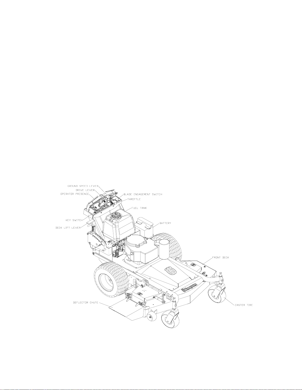
Table of Contents
SAFETY....................................................................................................................4
EQUIPMENT SETUP AND ADJUSTMENTS.............................................................5
CUTTING HEIGHT.....................................................................................................5
MOWER DECK LEVELING ...................................................................................... 5
MOTION CONTROL ADJUSTMENT.......................................................................... 6
BEL T ADJUSTMENTS..............................................................................................6
INTERLOCK SAFETY SYSTEM ...............................................................................6
NEUTRAL LOCK ADJUSTMENT..............................................................................7
GROUND SPEED NEUTRAL ADJUSTMENT...........................................................7
GROUND SPEED LEVER FRICTION....................................................................... 7
OPERA TING INSTRUCTIONS................................................................................... 8
MAINTENANCE INSTRUCTIONS .............................................................................9
MAINTENANCE CHART.......................................................................................... 12
TROUBLE SHOOTING.............................................................................................13
©2004 Husqvarna. All right reserved.
Beatrice, NE. Printed in U.S.A.
3
Page 4

TRAINING:
SAFETY
1. Read this manual carefully and question your
dealer if something is not clear.
2. Be thoroughly familiar with the controls and
proper use of the equipment.
3. Never allow children, teenagers, or people unfamiliar with these instructions to use the
mower.
4. Do not mow while people, particularly children,
or pets are nearby .
PREPARATION:
1. The use of personal protective equipment such
as (but not limited to) protection for the eyes,
ears, feet and head is recommended.
2. Never operate the mower without proper
guards, covers, safety switches and devices
in place and properly functioning. Inspect these
items daily for their condition and proper operation. If the condition or operation of any of
these devices is questionable they must be
replaced or repaired before using the mower .
3. Thoroughly inspect the area to be mowed and
remove all stones, sticks, wire and other debris that may be thrown by the mower. Also
note or mark other obstacles such as holes,
stumps, etc..
4. Do not operate the mower when barefoot or
wearing open shoes. Always wear subst antial
footwear and long pants.
5. Fill gas tank before starting mower. DO NOT
SMOKE near gasoline containers. Do not fill
gas tank indoors or when engine is hot or running. Clean off any spilled gasoline before starting the mower.
OPERATION:
1. Mow only in daylight or good artificial light.
2. Do not operate the mower in wet grass if possible.
3. Mow across slopes. Use extreme caution when
mowing or turning on slopes. Always turn to
the downhill side. Do not mow excessively
steep slopes ( mower may tip over and
cause injury or death ).
4. Use caution when backing up.
5. Stop the blades when crossing surfaces other
than grass; or when traveling to and from the
area to be mowed.
6. Never operate the mower with defective, broken or excessively worn parts. Keep all guards,
shields, and safety devices in place and in
proper working order.
7. Do not change the engine governor settings or
over speed the engine. Operating the engine
at excessive speeds will increase the hazard
of injury and can severely damage your machine.
8. Keep hands, feet and clothing away from rotating parts when operating mower.
9. Stop the blades and engine before leaving the
operators position for any reason.
10. Never make adjustments to the mower while
engine and/or blades are running.
1 1. After striking a foreign object, stop mower and
remove key. Inspect the mower for any damage and repair it immediately before continuing to mow.
12. Never operate this equipment in an enclosed
or confined area without proper ventilation of
the engine exhaust.
13. Do not allow any passengers to ride on the
mower. Keep others away from the mower
when in operation.
TRANSPORTATION:
Turn of f fuel valve and strap mower to trailer.
MAINTENANCE:
1. Keep all nuts, bolts and screws tight to keep
mower in safe operating condition.
2. Engine maintenance should comply with engine manufactures specifications. See the engine manual for specifications.
3. Never store the mower with gas in the tank inside a building where fumes can reach an open
flame or spark.
4. To reduce the risk of fire, keep the mower free
of grass, leaves and excessive grease or oil.
5. Have your mower inspected and serviced each
year by an authorized Husqvarna dealer.
6. Use only authentic Husqvarna replacement
parts to insure the safety and quality of your
mower is maintained.
7. Safety decals should be replaced if they are
missing or illegible. Decals can be purchased
from your Husqvarna dealer.
8. The hydraulic system including all hoses and
fittings should be checked frequently for wear
or leaks. Never check for leaks with your
hands, use a piece of cardboard or wood. Hydraulic oil under pressure could be injected into
your body and must be surgically removed
within a few hours.
4
Page 5
SETUP AND ADJUSTMENTS
1. Uncrate mower
2. Lift up on handles until mower is level.
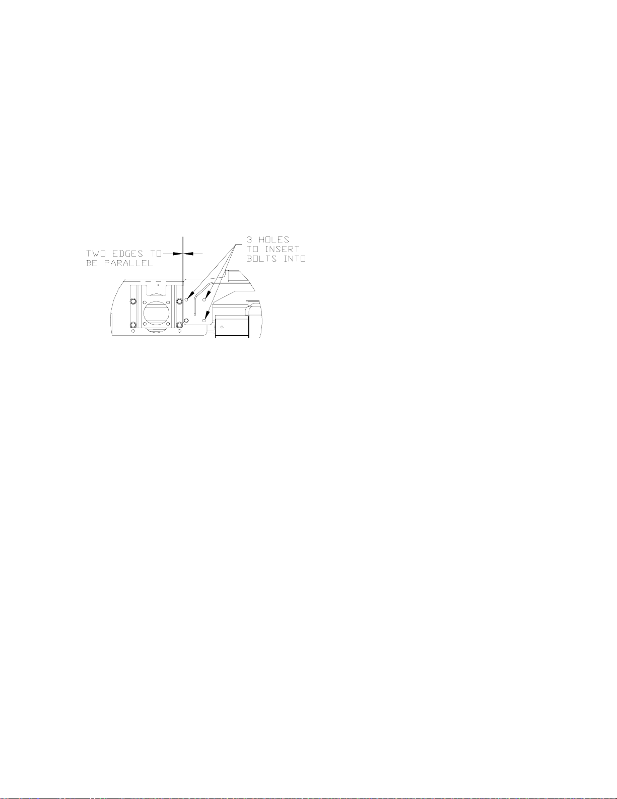
3. Using the hardware provided in the literature
package, insert 3 bolts per side into the frame
side where the front frame connects to the rear
deck. (See FIG 1) A pry bar can be used to
align the holes.
FIGURE 1
4. Line up the back edge of the front frame with
the front edge of the wheel motor mount so
they are parallel and tighten the hardware.
5. Remove the hood from the frame and install
the deck belt. Be sure the belt is still wrapped
around the clutch pulley under the rear
deck.(See FIG 2)
6. With the hood off, mount the muffler on the
engine using the provided hardware. Reinstall
hood.
7. Cut the plastic wire ties holding the operator
presence levers down.
8. Check tire pressure in all four tires. (rear tires
15 PSI, front tires 20-25 PSI)
9. Check engine oil with dipstick. Add if needed
per engine manufactures specifications. (See
engine manual)
10. Check hydraulic oil level. Should be an 1.0”
below the bottom of the fill tube.
11. Mount the discharge chute to the front deck
using the fasteners provided on the deck.
CUTTING HEIGHT:
1. Stop the mower and disengage the blades.
2. Raise the deck height lever to the transport position.
3. Remove the height adjustment pin and place it
in the desired cutting height hole. Move deck
height lever down onto the pin and mow.
NOTE: anti-scalp rollers must be in the proper
position for maximum deck floatation. See the
decal on the front deck.
MOWER DECK LEVELING:
1. Position mower on a flat surface and stop engine.
2. Check the tire pressure of all four tires. Inflation should be 15 psi.
3. Place two 2x4’s on edge under the cutting deck
from front to rear and lower the deck down onto
the 2x4’s.
4. Adjust the four upper chain bolts “H” to the center of the slot in the deck lift arms. NOTE: make
sure deck lift blocks are tightly bolted to the
frame .
5. Check chains for equal tension. If unequal,
adjust upper chain bolt in slot.
6. Place deck in the 5" cutting height and measure from the cutting edge of the blade to a flat
surface to check deck cutting height.
5
Page 6

SETUP AND ADJUSTMENTS
FRONT DECK BELT ROUTING:
FIGURE 2
PUMP BELT
1. Before performing adjustments on pump belt,
turn the mower off and disconnect spark plug
wire or wires.
2. Check tension on the belt. If it feels loose adjustment will need to be made.
3. Loosen the nut on the bottom of the idler pulley .
4. Slide the idler pulley against the belt, retighten
the nut while applying pressure to the idler pulley .
INTERLOCK SAFETY SYSTEM
The interlock safety system is to prevent the engine form starting if the blade switch is engaged or
the neutral lock bails is unlocked. It also causes
engine shutdown if the operator falls from, or attempts to leave the operator position while the
blades are engaged or the neutral lock bail is unlocked. After the engine starts, the operator must
hold either the left or right O.P. lever down before
engaging the blades or unlocking the neutral lock
bail. If neither O.P . lever is held the engine will stop.
Check the function of the safety electrical system
on a regular basis.
1. Engine must kill if blades are engaged without
at least one O.P. lever held down.
2. Engine must kill if the neutral lock bail is unlocked from the drive levers without holding
down at least one O.P. lever .
3. Engine must not start unless blades are off
and the neutral lock bail is locked in the drive
levers.
4. Do not operate the mower if the interlock safety
system allows operation or starting in any unsafe condition.
NEUTRAL LOCK ADJUSTMENT
Jack up the rear of the unit until the rear wheels
are off of the ground. Secure with jack stands.
Move the ground speed lever to the fast position. St art the mower, with the neutral lock bail
locked in the drive levers, check for tire rotation. Using two 9/16” open-end wrenches,
loosen the jam nut on the bottom of the turnbuckle on the motion control linkage. Turn the
turnbuckle until the tire stops turning. Holding
down the O.P . lever , release the neutral lock bail
from the drive levers. This will cause the tires to
rotate in full forward. Squeeze the drive levers
back and re-lock the neutral lock bail. Verify that
the tire is not turning. Retighten the 9/16” jam
nut. Repeat on other side if necessary .
GROUND SPEED NEUTRAL ADJUSTMENT
Jack up the rear of the unit until the rear wheels
are off of the ground. Secure with jack stands.
Verify that the neutral lock bail locked in the drive
levers. (See Neutral Lock Adjustments to adjust if necessary). Loosen the jam nut on the
ground speed stop bolt on the front of the console and back it out a little. Move the ground
speed lever to the rear position. If the tires do
not stop, adjustment of the tracking knob and
tracking bolt may be required. Loosen the jam
nut on the tracking bolt and turn it until the bolt
just contacts the drive left drive lever . T urn the
tracking knob until the threaded portion just contacts the right drive lever . Holding down the O.P .
lever, unlock the neutral lock bail. If the tires rotate, then the tracking
6
Page 7

SETUP AND ADJUSTMENTS
bolt and tracking knob will need to be turned in
the appropriate direction until the tires stop.
Move ground speed lever to the fast position
and back to stop. Verify that the tires stop. Adjust if necessary . Tighten jam nut on the tracking bolt. With the ground speed lever to the rear ,
turn the ground speed stop bolt until it just contacts the bottom of the ground speed lever . See
Figure 3. Tighten jam nut on ground speed stop
bolt. Reverify that all the tires stop with the ground
speed lever and the neutral lock bail.
FRICTION
PLATE
GROUND
SPEED
LEVER
GROUND
SPEED
ADJUSTMENT
BOLT
FIGURE 3
GROUND SPEED LEVER FRICTION
The ground speed lever has friction washers to
adjust the tension of the lever. To adjust, use
two 9/16” wrenches and tighten or loosen the
bolt and nut on each side of the friction plates.
See Figure 4.
TRACKING
BOL T
TRACKING
KNOB
GROUND
SPEED
ADJUSTMENT
BOLT
FIGURE 4
7
Page 8

OPERATION
CONTROLS:
1. Be thoroughly familiar with all controls their
function and how to operate them before operating the mower.
Drive levers: Located on each side of the handle
2.
control direction of movement. The left lever
controls the flow of oil from the left hydro pump
to the left wheel motor . The right lever controls
the flow of oil from the right hydro pump to the
right wheel motor.
3.
Ground speed lever: Located in the center of
the console. Controls the forward speed of the
mower. Push the lever forward if you want to
go faster, pull it back to go slower or pull it all
the way back to the neutral or stop position.
NOTE: To begin motion the operator must move
the ground speed lever forward before disengaging the neutral lock bail. After you release
the neutral lock bail allow the drive levers to
move forward at the same time. The mower
will move in a straight line in that direction.
Movement of the right drive lever forward will
cause the right wheel to rotate in a forward direction. Movement of the left drive lever forward will cause the left wheel to rotate in a forward direction. To stop forward travel, pull levers back into the stop position.
To turn right while moving in a forward direction pull the right drive lever back towards the
stop position, this will slow the right wheel and
cause the mower to turn in that direction.
To turn left while moving in forward direction
pull the left drive lever back towards the stop
position, this will slow the left wheel and cause
the mower to turn in that direction.
4. Blade engagement switch: Located on the left
side of the console. To engage the blades pull
up on the switch. Push down on the switch to
disengage the blades.
5. Throttle control: Located on the right side of
the console. Use the throttle to control the
engine RPM.
6.
Tracking knob: Located on the front side of the
ground speed lever. If the mower will not travel
in a straight line on a smooth surface, turn the
tracking knob the proper direction until it straightens out.
7.
Key switch: Located on the console. The key
switch must be turned on, blades disengaged,
and neutral lock bail locked in drive levers before starting.
8. Fuel shut off valve: Located under the tank support in the fuel line.
Pump release valves: Located at the back side
9.
of the pumps. Used to release the system so
unit may be moved by hand when not running.
NOTE: Only rotate about a 1/4 to 1/2 of a turn
to release system.
10.
Operator presence levers: Located on the
handle. One or both levers must be pressed
against the handle for the mower to remain running, when the blades are engaged or the
ground speed lever is not in the neutral position.
11. Choke control: Use when starting cold engine
do not run choke when engine is warm.
ST ARTING AND OPERA TION:
1. Making sure the blades are disengaged, the
neutral lock bail locked, and the fuel valve on.
2. Adjust choke (if needed) turn key to on posi-
tion.
3. Start the engine. Once the engine is running
adjust the throttle.
4. Holding down at least one of the operator pres-
ence levers, engage blades and set RPM to
maximum. NOTE: Be sure all persons are
clear of area before engaging the blades. To
prolong spindle bearing and belt life engage
and disengage blades at approximately 1\2
throttle.
5. Set the ground speed lever to the desired po-
sition.
6. Release the neutral lock bail.
8
Page 9

MAINTENANCE
1.
Engine oil level: Check daily with engine cold
and on a flat surface. Remove the dipstick and
wipe clean. Reinsert the dipstick all the way,
but do not screw down. Remove the dipstick
and check oil level. If oil level is low add oil.
Use engine manufacturers specs for type of
oil.
2. Pump drive belt: Stop engine and remove key .
Check the tension on the belt.
3. Mower blades: Stop engine and remove key.
Inspect blades and sharpen or replace as
needed. Check daily or more often if needed.
The machine requires more power with dull
blades and gives a poor cut. If blades get bent,
replace them. Blades shouldn’t have any
notches from hitting objects. The air foil on
top of the blade should be sufficient to raise
the grass for cutting. If blades are in good condition, sharpen at an angle of 22 to 28 degrees
about 2-1/2 inches in from the tips. Note: After
sharpening, check blades for proper balance,
if needed correct balance to prevent excessive vibration.
of clean oil on the filter gasket before installing. Fill engine with oil using manufacturers
specs, see Kawasaki owner’s manual. Start
engine and idle slowly to allow the oil to recoat
the interior of the engine and then inspect for
leaks.
8. Hydraulic oil: Check daily. Thoroughly clean
around cap. Remove cap. Oil level should be
1” below the bottom of the fill tube. If not, add oil.
NOTE: Use only synthetic 15W - 50 Mobil 1.
9. Tire pressure: Check every 25 to 50 hours.
Rear tires require 15 psi and caster tires 20
psi
10. Belts: Check every 25 hours. S top engine and
remove key . Check the condition of all belt s.
12. Lubrication (every 25 hours): Caster tires and
front caster pivots
(Clean grease zerk thoroughly before greasing)
13. Fuel filter: Replace annually or as needed.
4. Safety interlock system: Check daily and never
operate the mower if this system is not functioning properly .
Hardware: Stop engine and remove key thor-
5.
oughly inspect the entire machine for any missing or loose hardware. Check daily .
6. Air cleaner: Stop engine and remove key. Remove plastic cover and loosen wingnut on the
air cleaner. Remove the foam pre-cleaner and
wash or replace if needed. Inspect paper filter
and replace if dirty . Check every 25 hours, daily
if in very dirty conditions. Fuel efficiency, engine RPM, and available power goes down rapidly if the air filter is dirty. Prolonged effects
could damage the engine.
7. Engine oil: Change oil to manufacturers specifications. Stop engine and remove key. Drain
oil when engine is warm. Thoroughly clean
around cap before removing. Remove oil
drain cap from the right side of engine block
and replace drain cap. Remove oil filter and
replace. Put a light coat
14. Hydraulic filter and oil: Change every 500 hours
or yearly . Stop engine and remove key . Clean
around the filter and the drain plug on the bottom side of the tank. Remove the filter and allow any oil to drain from the filter head. Then
replace with new filter. Use only Husqvarna
p/n 102606, filter which has a bypass valve
and the correct micron filter. Remove one of
the hydraulic lines from the bottom of the tank
and allow the tank to drain, reinstall the hydraulic line. Fill tank with synthetic 15W - 50
Mobil 1. 1” below the fill tube and replace cap.
Block up the rear of unit until wheels will rotate
freely and start engine at a slow idle, move
the control levers forward and run for several
minutes. Stop engine and recheck oil level. If
wheels don’t response an air lock has occurred
within the hydraulic system. Bleed air from
lines, or let stand overnight to allow the air time
to dissipate out of the oil. Retry responses &
check the oil level. Note: Serious damage to
the pumps and wheel motors can occur if the
system is ran with an air lock.
9
Page 10

MAINTENANCE
CUTTER HOUSING SPINDLE
ASSEMBLYS
Grease housings once weekly or every 40 to 50 hours of use. Use a good synthetic grease. Pump grease
in until a small amount purges from the popet on the underside of the deck. Check the torque of the pulley
bolt (45 ft/lbs) should be maintained.
SPINDLE ASSEMBLY
ZERK
SPECIAL BOL T
LOCKWASHER
HEAV Y WASHER
PULLEY
TOP DUST CAP
SHAFT SEAL
SP ACER
539108763
BEARING
BUSHING
HOUSING
POPPET
SP ACER
BUSHING
BEARING
SPACER
SHAFT SEAL
BOTTOM DUST CAP
SPINDLE SHAFT
BLADE SPACERS
BLADE
10
LOCKWASHER
BLADE BOLT
Page 11

MAINTENANCE
WINTER STORAGE
To prepare your Husqvarna mower for winter
storage, perform the routine maintenance and
necessary adjustments and record the part
numbers of worn or broken parts so they may be
ordered and replaced before the next mowing
season. Use only authentic Husqvarna
replacement parts to insure proper fit and the
saftey of your mower is maintained.
Treat the fuel in the tank with a fuel stablizer (such
as STA-BIL). This will minimize the formation of
fuel gum deposits during storage. Read and follow
the mix ratio on the container. Run the engine for
at least 10 minutes after adding the stablizer to
bring it into the carburetor.
These few tips will help make your mower
ready when needed for the next mowing
season and insure many years of
dependable service.
11
Page 12

MAINTENACNE CHART
Maintenance
Engine (4)
Hydraulics
Electrical
Lubricate
Maintance Interval (hours)
Daily 25 50 100 200 250 500
Check oil level X
Change oil and filter (1) X
Clean the air filter’s (3) X
Replace air filter’s (3) X
Check for fuel and oil leakage X
Clean cooling flanges (3) X
Check cooling air inlet X
Replace fuel filter X
Replace plugs X
Check oil level X
Check for oil leaks X
Change hydraulic oil (2) XX
Change oil filter (2) XX
Check battery X
Check the safety system X
Left and right deck struts X
Deck idler arm X
Caster swivels X
Caster tires X
Deck lift lever X
Throttle cable X
Choke cable X
Cutter housings X
Deck bell cranks X
Lift lever X
General
Notes:
Check bolts and nuts X
Check cutting deck X
Clean cutting deck (3) X
Clean pump compartment (3) X
Check tire pressure (15 psi) X
Check belts X
Check and adjust throttle cable X
1. Change engine oil and filter after first 50 hours and then every 100 hours.
2. Change hydraulic oil and filter after the first 250 hours or season and then every 500 hours.
3. During dusty or dry conditions cleaning and replacement should be more frequent.
4. Refer to engine manual for more information.
12
Page 13

TROUBLE SHOOTING
PROBLEM POSSIBLE CAUSES
Engine won’t start
Mower will not move
or moves slowly or with
difficulty
Blades won’t engage
Uneven cut
1. Blade switch engaged.
2. Neutral lock bail not locked.
3. Fuel valve closed.
4. No fuel.
5. Sp ark plug wires off.
6. Bad spark plugs.
7. Blown fuse.
1. Pump bypass valves open.
2. Pump drive belt loose or off.
4. Hydraulic system failure.
5. Air in the hydraulic system.
1. Blade belt off of pulleys.
2. Blown fuse.
1. Tire pressure uneven.
2. Blades bent (check tip to tip one blade thickness)
3. Air foil of blade worn or bent.
Cut is ragged
Mower moves when
in neutral position
Mower pulls left or right
When a problem occurs, do not overlook the simple causes.
1. Blades dull.
2. Ground speed too fast.
3. Grass accumulation under deck.
1. Motion control linkage out of adjustment.
2. Pump arms loose or out of adjustment.
1. Tire pressure uneven.
2. Motion control linkage adjustment.
3. Soft terrain.
4. Slope too steep.
5. Tracking not adjusted.
13
Page 14

 Loading...