

Husqvarna TC 250R (2013), TE 310R USA (2013), TXC 250R USA (2013), TE 310R (2013), TXC 310R USA (2013) Workshop Manual
...Page 1

TE 250R - 310R 2013 I.E.
TE 310R 2013 I.E. USA
TC 250R 2013 - TC 250R 2013 I.E. USA
TXC 250R - 310R 2013 I.E. USA
Workshop Manual Ed. 07-2012
Rev 00
Page 2

HUSQVARNA MOTORCYCLES S.R.L. - Varese disclaims all liabilities for any errors or omissions in this manual and
reserves the right to make changes to reect on-going product development. Illustrations in the manual may differ from
actual components. No reproduction in full or in part without written authorisation.
1st edition (07-2012) - Rev. 00
Page 3
a.1
simbolo
TE 250R - 310R 2013 I.E. / TE 310R 2013 I.E. USA
TC 250R 2013 - TC 250R 2013 I.E. USA
TXC 250R - 310R 2013 I.E. USA
TE 250R - 310R 2013 I.E.
TE 310R 2013 I.E. USA
TC 250R 2013 - TC 250R 2013 I.E. USA
TXC 250R - 310R 2013 I.E. USA
TE 250R: ZKHA300AADV000001
TE 310R: ZKHA301AADV000001
TE 310R USA: ZKHKCEDG#DV000001
TC 250R: ZKHA300AADV050001
TC 250R USA: ZKHTC253#DV000001
TXC 250R USA: ZKHTX253#DV000001
TXC 310R USA: ZKHTX313#DV000001
H11268
1
Workshop Manual Ed. 07-2012
FOREWORD, TABLE OF CONTENTS
1st edition (07-2012) - Rev. 00
Printed in Italy
MODELS COVERED (from serial number onwards)
Copyright by
HUSQVARNA MOTORCYCLES S.R.L.
BMW Group
Technical Service
Via Nino Bixio, 8
21024
(Varese) - Italy
tel. ++39 0332 75.61.11
tel. ++39 0332 756 558
www.husqvarna-motorcycles.com
Workshop Manual
1. Chassis serial number
Page 4
a.2
simbolo
TE 250R - 310R 2013 I.E. / TE 310R 2013 I.E. USA
TC 250R 2013 - TC 250R 2013 I.E. USA
TXC 250R - 310R 2013 I.E. USA
FOREWORD, TABLE OF CONTENTS
Workshop Manual Ed. 07-2012
Foreword
This publication is designed for use by HUSQVARNA Service Centres to assist authorised personnel in the maintenance
and repair of the models covered in this manual. The technical information provided in this manual is a critical complement to operator training and operators should become thoroughly familiar with it.
For ease of understanding, diagrams and photographs are provided next to the text.
Notes with special signicance are identied as follows throughout the manual:
Accident-prevention rules for operator and persons working nearby.
Damage to vehicle and/or its components may result from incompliance with relevant instructions.
Additional information concerning the operation covered in the text.
Useful tips
To prevent problems and ensure effective service work, observe the following HUSQVARNA recommendations:
– before repair, evaluate the customer's description of the problem and ask the appropriate questions to clearly identify
problem symptoms;
– diagnose the problem and identify the causes clearly. This manual provides basic background information that must
be supplemented with the operator's expertise and specic training available through HUSQVARNA held at regular
periods;
– plan ahead before starting work: gather any spare parts and tools to avoid unnecessary delays;
– avoid unnecessary disassembly work to get to the part that needs repairing.
Always read the relevant instructions and follow the disassembly sequence outlined in this manual.
Recommended shop practices
1 Always replace gaskets, sealing rings and split pins with new ones.
2 When loosening or tightening nuts or bolts, always begin with the bigger ones or from the centre. Tighten to the speci-
ed torque and follow a cross pattern.
3 Always mark any parts or positions that might be confused upon assembly.
4 Use genuine HUSQVARNA parts and the recommended lubricant brands.
5 Use special tools where specied.
6 Technical Bulletins might contain more up-to-date setting data and procedures than this manual. Be sure to read
them.
Page 5

a.3
simbolo
TE 250R - 310R 2013 I.E. / TE 310R 2013 I.E. USA
TC 250R 2013 - TC 250R 2013 I.E. USA
TXC 250R - 310R 2013 I.E. USA
Workshop Manual Ed. 07-2012
FOREWORD, TABLE OF CONTENTS
Table of Contents
Title Section
Foreword, table of contents .................................................................................a
Important notices .................................................................................................b
General information
.............................................................................................A
Maintenance ........................................................................................................B
Troubleshooting
.................................................................................................. C
Settings and adjustments ................................................................................... D
General procedures .............................................................................................E
Engine disassembly.............................................................................................F
Engine overhaul.................................................................................................. G
Engine reassembly ............................................................................................. H
Front suspension ..................................................................................................I
Rear suspension.................................................................................................. J
Brakes .................................................................................................................L
Electrical system.................................................................................................M
Engine cooling .................................................................................................... N
Hydraulically controlled clutch .............................................................................P
Fuel injection system ...........................................................................................S
Special tools .......................................................................................................W
Tightening torque gures .....................................................................................X
Chassis and wheels.............................................................................................Y
NOTES
Unless otherwise specied, data and specications apply to all models.
Page 6

Page 7

b.1
TE 250R - 310R 2013 I.E. / TE 310R 2013 I.E. USA
TC 250R 2013 - TC 250R 2013 I.E. USA
TXC 250R - 310R 2013 I.E. USA
b
Workshop Manual Ed. 07-2012
IMPORTANT NOTICES
Section
Page 8

b.2
TE 250R - 310R 2013 I.E. / TE 310R 2013 I.E. USA
TC 250R 2013 - TC 250R 2013 I.E. USA
TXC 250R - 310R 2013 I.E. USA
H11269
TE
H11270
TXC
H11271
TC
IMPORTANT NOTICES
Workshop Manual Ed. 07-2012
1) TC, TXC models are RACING motorcycles and are warranted to be free from
operating defects; a scheduled maintenance chart for racing use is provided in
Section B.
2) The TE model is for ROAD USE (DERATED); it is warranted to free from
defects and covered by legal warranty, provided that the STANDARD CONFIGURATION IS MAINTAINED and the maintenance chart provided in Section
B is observed. For TE models modied to RACING SPECIFICATIONS (FULL
POWER RATING), observe the scheduled maintenance chart for racing use
provided in Section B.
* This motorcycle has not been designed to travel over long distances with the
engine at top rpm, as in long-distance road or highway travel. Riding over long
distances at full throttle may result in severe engine damage.
* The geometry and setup of this motorcycle have been designed for racing
and to provide top performance when riding solo. We advise against riding
two-up, whether off-road or on the track.
* ALWAYS remember that these motorcycles are specically designed for
racing, i.e. for usage conditions signicantly different from those experienced
in regular road use.
IMPORTANT
VEHICLE CONFIGURATION as outlined below is a prerequisite for the warranty to remain valid:
A) STANDARD MOTORCYCLE, FOR ROAD USE: DERATED;
B) RACING MOTORCYCLE, FOR RACING USE: FULL POWER RATING.
* In order to maintain the vehicle’s “Guarantee of Functionality”, the client must
follow the maintenance programme indicated in Section B by having the required
maintenance inspections carried out at authorised HUSQVARNA dealers. The
cost for changing parts and for the labour necessary in order to comply with
the maintenance plan is charged to the Client. The warranty becomes NULL
AND VOID if the motorcycle is rented.
Notes
Left and right side is determined when seated on motorcycle.
Z: number of teeth
A: Austria
AUS: Australia
B: Belgium
BR: Brazil
CDN: Canada
CH: Switzerland
D: Germany
E: Spain
F: France
FIN: Finland
GB: Great Britain
I: Italy
J: Japan
USA: United States of America
Unless otherwise specied, data and instructions apply to all market variants.
Page 9

A.1
TE 250R - 310R 2013 I.E. / TE 310R 2013 I.E. USA
TC 250R 2013 - TC 250R 2013 I.E. USA
TXC 250R - 310R 2013 I.E. USA
A
Workshop Manual Ed. 07-2012
GENERAL INFORMATION
Section
Page 10

A.2
TE 250R - 310R 2013 I.E. / TE 310R 2013 I.E. USA
TC 250R 2013 - TC 250R 2013 I.E. USA
TXC 250R - 310R 2013 I.E. USA
GENERAL INFORMATION
Workshop Manual Ed. 07-2012
Sommario
Engine ..........................................................................................................A.3
Starting .........................................................................................................A.3
Timing system ..............................................................................................A.3
Lubrication ....................................................................................................A.3
Ignition ..........................................................................................................A.3
Fuel system ..................................................................................................A.3
Primary drive ................................................................................................A.3
Clutch ...........................................................................................................A.3
Transmission ................................................................................................A.4
Secondary drive............................................................................................A.4
Final ratios (TE) ............................................................................................A.4
Final ratios (TXC) .........................................................................................A.4
Final ratios (TC)
............................................................................................A.4
Frame ...........................................................................................................A.4
Front suspension ..........................................................................................A.4
Rear suspension...........................................................................................A.5
Front brake ...................................................................................................A.5
Rear brake
....................................................................................................A.5
Rims .............................................................................................................A.5
Tires ..............................................................................................................A.5
Cold tire pressure
.........................................................................................A.5
Electrical components location (TC)
.............................................................A.6
Electrical components location (TXC)
..........................................................A.6
Electrical components location (TE)
.............................................................A.6
Overall dimensions .......................................................................................A.7
Weight
..........................................................................................................A.8
Capacities
.....................................................................................................A.8
Page 11

A.3
TE 250R - 310R 2013 I.E. / TE 310R 2013 I.E. USA
TC 250R 2013 - TC 250R 2013 I.E. USA
TXC 250R - 310R 2013 I.E. USA
Workshop Manual Ed. 07-2012
GENERAL INFORMATION
Engine
Type .............................................................................. single cylinder, 4 stroke
TE-TXC 250R - 310R
Cooling ..........................................................liquid, with electric fan on models
TC 250R
Cooling ......................................................................................................liquid
TE-TXC 250R + TC 250R
Bore ..........................................................................................3,11 in. (79 mm)
Stroke .................................................................................. 2,00 in. (50,9 mm)
Displacement ...............................................................15,22 cu. in. (249,5 cm3)
Compression ratio
....................................................................................13,6:1
TE-TXC 310R
Bore
......................................................................................... 3,23 in. (82 mm)
Stroke ................................................................................... 2,26 in. (57,3 mm)
Displacement
.............................................................18,46 cu. in. (302,44 cm3)
Compression ratio ......................................................................................13:1
Starting
TE-TXC 250R - 310R ............................................................................ electric
TC 250R
............................................ kick start (with automatic decompressor)
Timing system
Type .......................................................................................4 titanium valves,
controlled by twin nger follower type camshafts, mixed chain/gear drive system
Valve clearance (with engine cold)
Intake .................................................................................. 0,006 in. (0,15 mm)
Exhaust............................................................................... 0,008 in. (0,20 mm)
Lubrication
Type ......................... wet crankcase, lobe pump and cartridge and mesh lters
Ignition
Type ..................................................................Electronic, inductive discharge,
with adjustable advance (digital control)
Spark plug type..........................................................................NGK CR9EIA-9
Spark plug gap
....................................................0.031÷0,035 in. (0,8÷0,9 mm)
Fuel system
Type .............................................................................Electronic injection feed
Primary drive
Drive pinion gear- Clutch ring gear
................................................... Z 17- Z 54
Transmission ratio
....................................................................................3,176
Clutch
Type
.............................................oil bath multiple disc clutch, hydraulic control
Page 12
A.4
TE 250R - 310R 2013 I.E. / TE 310R 2013 I.E. USA
TC 250R 2013 - TC 250R 2013 I.E. USA
TXC 250R - 310R 2013 I.E. USA
GENERAL INFORMATION
Workshop Manual Ed. 07-2012
Transmission
Type ............................................................................ constant mesh gear type
TE-TXC 250R - 310R
Transmission ratio
1st gear...................................................................................... 2,142 (z 30/14)
2nd gear .................................................................................... 1,750 (z 28/16)
3rd gear ..................................................................................... 1,450 (z 29/26)
4th gear ..................................................................................... 1,227 (z 27/22)
5 th gear .................................................................................... 1,041 (z 25/24)
6 th gear .................................................................................... 0,884 (z 22/27)
TC 250R
Transmission ratio
1st gear. ..................................................................................... 2,142 (z 30/14)
2nd gear .................................................................................... 1,750 (z 28/16)
3rd gear .................................................................................... 1,450 (z 29/26)
4th gear...................................................................................... 1,227 (z 27/22)
5 th gear..................................................................................... 1,041 (z 25/24)
Secondary drive
Transmission sprocket- Rear wheel sprocket
TXC + TC...........................................................................................Z 13- Z 50
TE ......................................................................................................Z 13- Z 40
Transmission ratio
TXC + TC..................................................................................................3,846
TE ..............................................................................................................3,076
Final ratios (TE)
1st gear ...................................................................................................20,926
2nd gear ..................................................................................................17,096
3rd gear ..................................................................................................14,165
4th gear ..................................................................................................11,987
5th gear ..................................................................................................10,169
6th gear ....................................................................................................8,636
Final ratios (TXC)
1st gear....................................................................................................26,164
2nd gear .................................................................................................21,376
3rd gear ..................................................................................................17,251
4th gear ...................................................................................................14,987
5th gear ...................................................................................................12,715
6th gear ...................................................................................................10,797
Final ratios (TC)
1st gear....................................................................................................26,180
2nd gear ..................................................................................................21,380
3rd gear ...................................................................................................17,715
4th gear ...................................................................................................14,994
5th gear ...................................................................................................12,726
Frame
Type ................... Steel single tube cradle (roud, rectangular, ellipsoidal tubes);
light alloy rear frame
Front suspension
Type ............."Upside-down" telescopic hydraulic front fork with advanced axle
(adjustable in compression and rebound stroke);
stanchions tubes Ø 1.89 in. (Ø 48 mm)
Legs axis stroke......................................................................11.8 in. (300 mm)
Page 13
A.5
TE 250R - 310R 2013 I.E. / TE 310R 2013 I.E. USA
TC 250R 2013 - TC 250R 2013 I.E. USA
TXC 250R - 310R 2013 I.E. USA
Workshop Manual Ed. 07-2012
GENERAL INFORMATION
Rear suspension
Type ...................................... progressive with hydraulic single shock absorber
Wheel stroke...........................................................................11.6 in. (296 mm)
Front brake
Type ................................................. xed disc Ø 10.23 in. (Ø 260 mm) “Wave”
type with hydraulic control and oating caliper
Rear brake
Type .............................................. oating disc, Ø 9.45 in. (Ø 240 mm) “Wave”
type with hydraulic control and oating caliper
Rims
Front ..................................................................................in light alloy: 1,6x21”
TE-TXC 250R - 310R
Rear .................................................................................in light alloy: 2,15x18”
TC 250
Rear .................................................................................in light alloy: 1,85x19”
Tires
TE-TXC 250R- 310R
Front ...................................................................................................90/90x21”
TC 250R
Front ...............................................................................................80/100 x 21”
Rear TE - TXC ................................................................................. 120/90x18”
Rear TE USA ................................................................................... 140/90x18”
Rear TC ........................................................................................... 100/90x19”
Cold tire pressure
Front TE - TXC - TC (*) .............................................................. 0,9÷1,0 Kg/cm
2
Front TE - TXC (%) .......................................................................... 1,1 Kg/cm
2
Rear TE - TXC - TC (*) .............................................................. 0,8÷0,9 Kg/cm
2
Rear TE - TXC (%) .......................................................................... 1,0 Kg/cm
2
(*) In case of racing use - (%) Road use
Page 14

A.6
TE 250R - 310R 2013 I.E. / TE 310R 2013 I.E. USA
TC 250R 2013 - TC 250R 2013 I.E. USA
TXC 250R - 310R 2013 I.E. USA
GENERAL INFORMATION
Workshop Manual Ed. 07-2012
Electrical components location (TC)
The ignition system includes the following elements:
- Generator on the inner side of L.H. crankcase half cover;
- Integrated electronic ignition coil on the spark plug cap;
- Electronic control unit under the fuel tank;
- Spark plug on cylinder head;
- Throttle position sensor on the throttle body;
- MAP Sensor on the throttle body;
- Condenser on the left of rear chassis;
- Voltage regulator under the reservoir;
- Air temperature sensor on intake lter.
Electrical components location (TXC)
The ignition system includes the following elements:
- Generator on the inner side of L.H. crankcase half cover;
- Integrated electronic ignition coil on the spark plug cap;
- Electronic control unit under the fuel tank;
- Voltage regulator located to the left side of the motorcycle near the steering tube;
- Spark plug on cylinder head;
- 12V-450W starter motor behind the engine cylinder;
- Solenoid starter on the left of rear chassis;
- Throttle position sensor on the throttle body;
- MAP Sensor on the throttle body;
- Air temperature sensor on intake lter.
The electrical system includes the following elements:
- 12V-6Ah battery under the saddle;
- Electric fan;
- Two 15A and 20A fuses located to the right of the rear chassis, plus one 20A fuse on the starter relay;
- Coolant temperature sensor;
- Lambda sensor;
- Fuel pump inside the fuel tank.
- Fuel and reserve indicator.
Electrical components location (TE)
The ignition system includes the following elements:
- Generator on the inner side of L.H. crankcase half cover;
- Integrated electronic ignition coil on the spark plug cap;
- Electronic control unit under the fuel tank;
- Voltage regulator located to the left side of the motorcycle near the steering tube;
- Spark plug on cylinder head;
- 12V-450W starter motor behind the engine cylinder;
- Solenoid starter on the left of rear chassis;
- Throttle position sensor on the throttle body;
- MAP Sensor on the throttle body;
- Air temperature sensor on intake lter.
The electrical system includes the following elements:
- 12V-6Ah battery under the saddle;
- Turning indicator asher on left side of rear chassis;
- Injection and lighting system relay on the right side of the chassis;
- Electric fan;
- Three fuses (two 15A fuses and one 20A fuse), located to the right of the rear chassis, plus one 20A fuse on the starter relay;
- Coolant temperature sensor;
- Lambda sensor;
- Headlamp with 12V-35/35W twin halogen bulb and 12V-5W parking light bulb;
- LED tail light with stop light bulb;
- 12V-10W turning indicator bulbs;
- Fuel pump inside the fuel tank.
- Odometer.
Page 15
A.7
TE 250R - 310R 2013 I.E. / TE 310R 2013 I.E. USA
TC 250R 2013 - TC 250R 2013 I.E. USA
TXC 250R - 310R 2013 I.E. USA
H11272
C
D
E
F
A
B
Workshop Manual Ed. 07-2012
GENERAL INFORMATION
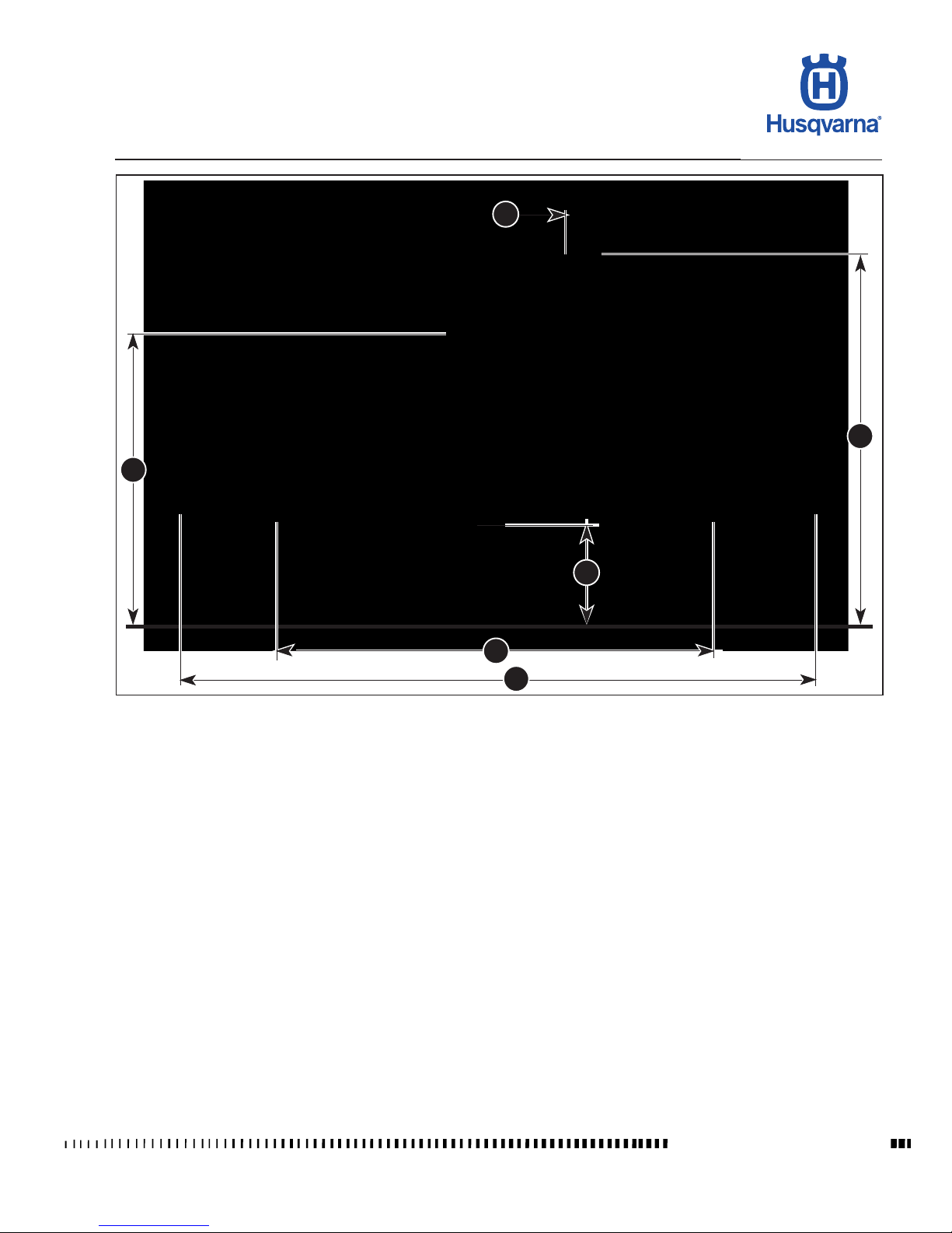
Overall dimensions
Wheelbase A
(TE-TXC) ........................................................................... mm 1460 (57.47 in.)
(TC) ................................................................................... mm 1470 (57.87 in.)
Overall length B
(TC) ................................................................................... mm 2215 (87.20 in.)
(TE) .................................................................................... mm 2260 (88.97 in.)
(TXC) ................................................................................. mm 2176 (85.66 in.)
Overall width C .................................................................... mm 820 (32.28 in.)
Overall height D
(TE-TXC) ........................................................................... mm 1290 (50.78 in.)
(TC) ................................................................................... mm 1305 (51.37 in.)
Saddle height E
(TC) ..................................................................................... mm 985 (38.77 in.)
(TE-TXC) ............................................................................. mm 950 (37.40 in.)
Minimum ground clearance F
(TE-TXC) ..............................................................................mm 290 (11.41 in.)
(TC) ..................................................................................... mm 325 (12.79 in.)
Page 16

A.8
TE 250R - 310R 2013 I.E. / TE 310R 2013 I.E. USA
TC 250R 2013 - TC 250R 2013 I.E. USA
TXC 250R - 310R 2013 I.E. USA
GENERAL INFORMATION
Workshop Manual Ed. 07-2012
Weight
(TC)
Kerb weight, without fuel: .....................................................101,2 Kg (213,8 lb)
(TE)
Kerb weight, without fuel:
.........113 Kg (249,1 lb) 250 / 113,5 Kg (250,2 lb) 310
(TXC)
Kerb weight, without fuel:
.....108,6 Kg (239,4 lb) 250 / 109,1 Kg (240,5 lb) 310
Capacities Type Quantity
Fuel tank (TC) Premium grade unleaded fuel (R.O.N. 98) 6,5 liters
Imp. Gall. 1.43
U.S. Gall. 1.72
Fuel tank (TE-TXC) Premium grade unleaded fuel (R.O.N. 98) 8,5 liters
(2,3 liters - 0.51 Imp. Gall. - 0.61 U.S. Gall. reserve included)
Imp. Gall. 1.87
U.S. Gall. 2.25
Gearbox/engine oil CASTROL POWER 1 RACING (SAE 10W50) 900 cc
(oil change and oil lter
replacement)
850 cc
(oil change)
Front fork oil KAYABA KHL15-11 (SAE 7,5; SAE 5 for extremely cold weather)
Oil quantity in each fork leg (TC - TXC)
556 cm3 (33.93 in3)
Cartridge: 196 cm3 (11.96 in3)
Fork sleeve: 360 cm3 (21.97 in3)
Oil quantity in each fork leg (TE)
674 cm3 (41.13 in3)
Rear shock absorber oil CASTROL SYNTHETIC FORK OIL (5W)
Coolant CASTROL MOTORCYCLE COOLANT 0.9 litres
0,24 U.S. Gall.
0,2 Imp. Gall.
Front brake uid CASTROL RESPONSE SUPER (DOT 4)
Rear brake uid CASTROL RESPONSE SUPER (DOT 4)
Clutch uid CASTROL RESPONSE SUPER (DOT 4)
Drive chain lubrication CASTROL CHAIN LUBE RACING
Grease lubrication CASTROL PASTE TA GREASE
Electric contact protection CASTROL METAL PARTS CLEANER
CASTROL MOTORCYCLE DWF
Fillers for radiator AREXONS LIQUID FILLER
Front fork oil: Kayaba KHL15-11
Air lter oil AGIP FORMULA FILTER "Foam air lter protection oil"
Air lter detergent AGIP "Filter clean foam air detergent uid"
IMPORTANT - Do not add any additives to fuel or lubricants.
Page 17

B.1
TE 250R - 310R 2013 I.E. / TE 310R 2013 I.E. USA
TC 250R 2013 - TC 250R 2013 I.E. USA
TXC 250R - 310R 2013 I.E. USA
B
Workshop Manual Ed. 07-2012
MAINTENANCE
Section
Page 18
B.2
TE 250R - 310R 2013 I.E. / TE 310R 2013 I.E. USA
TC 250R 2013 - TC 250R 2013 I.E. USA
TXC 250R - 310R 2013 I.E. USA
MAINTENANCE
Workshop Manual Ed. 07-2012
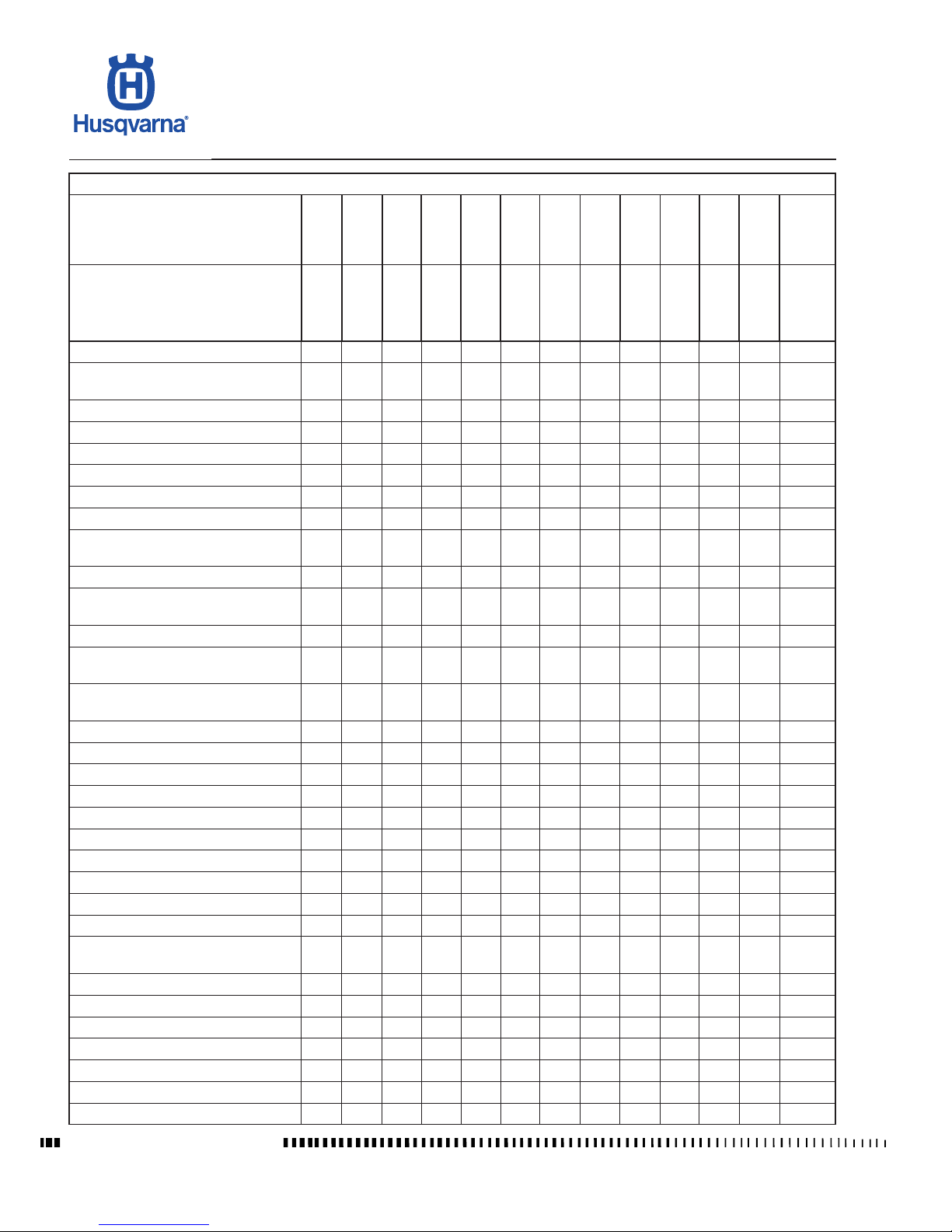
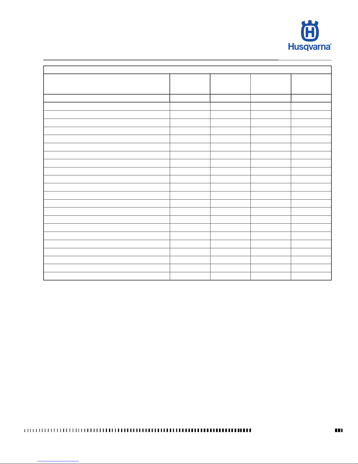
SCHEDULED MAINTENANCE CHART (TO BE CARRIED OUT AT THE HUSQVARNA DEALER)
TXC - TE 250R / TXC - TE 310R
RACING MOTORCYCLE, FOR RACING USE: FULL POWER RATING
AFTER THE
FIRST 2,5 h
EVERY 5 h
EVERY 10 h
EVERY 20 h
EVERY 30 h
EVERY 40 h
EVERY 50 h
EVERY 60 h
EVERY 70 h
EVERY 80 h
EVERY 90 h
EVERY
100 h
REPLACE
AS
REQUIRED
PARTICOLARE
CHECK
CHECK
SERVICE
COUPON
SERVICE
COUPON
SERVICE
COUPON
SERVICE
COUPON
SERVICE
COUPON
SERVICE
COUPON
SERVICE
COUPON
SERVICE
COUPON
SERVICE
COUPON
SERVICE
COUPON
AIR FILTER
P,L P,L
REAR CHASSIS MNTG BOLTS, ENGINE MNTG BOLTS
C C
WHEEL SPOKE TENSION
C C
SPROCKET BOLT TIGHTENING
C C
TORQUE OF NUTS AND BOLTS
C C
COOLANT
C X,
*
BRAKE PADS
C X
REAR CHAIN SPROCKET
C X
HANDLEBAR MOUNTS AND FASTENERS
C
REAR SWINGING ARM BUSHING
L
REAR SUSPENSION LINKAGE BUSHINGS
L
CHAIN GUIDE/CHAIN GUARD
C X
SWINGING ARM AXLE ROLLER
CAGES
L
ROLLER CAGES, LINKAGE PINS OF
REAR SUSP.
L
COMPLETE THROTTLE CONTROL
C, L
EXHAUST PIPE AND SILENCER
C X
FUEL PIPES
C S X
SECONDARY DRIVE CHAIN
C, L C, L X
KICK START PEDAL
L
GEAR SHIFT PEDAL
C
RADIATORS
C
WATER HOSES AND CLAMPS
C
RADIATORS TO WATER PUMP HOSE
C
FOOTPEGS, PINS, SPRINGS
C X
STEERING HEAD, BOTTOM YOKE
WITH STEM
L
REAR CHAIN SLIDER
C X
FRONT BRAKE DISC
C X
REAR BRAKE DISC
C X
CHAIN GUIDE ROLLER, BEARINGS
C
SIDESTAND
C
COMPLETE CLUTCH CONTROL
R
THROTTLE CABLES
C/L X
Page 19
B.3
TE 250R - 310R 2013 I.E. / TE 310R 2013 I.E. USA
TC 250R 2013 - TC 250R 2013 I.E. USA
TXC 250R - 310R 2013 I.E. USA
Workshop Manual Ed. 07-2012
MAINTENANCE
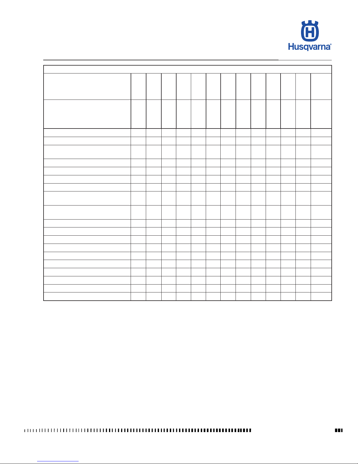
SCHEDULED MAINTENANCE CHART (TO BE CARRIED OUT AT THE HUSQVARNA DEALER)
TXC - TE 250R / TXC - TE 310R
RACING MOTORCYCLE, FOR RACING USE: FULL POWER RATING
AFTER THE
FIRST 2,5 h
EVERY 5 h
EVERY 10 h
EVERY 20 h
EVERY 30 h
EVERY 40 h
EVERY 50 h
EVERY 60 h
EVERY 70 h
EVERY 80 h
EVERY 90 h
EVERY
100 h
REPLACE
AS
REQUIRED
PARTICOLARE
CHECK
CHECK
SERVICE
COUPON
SERVICE
COUPON
SERVICE
COUPON
SERVICE
COUPON
SERVICE
COUPON
SERVICE
COUPON
SERVICE
COUPON
SERVICE
COUPON
SERVICE
COUPON
SERVICE
COUPON
FRONT BRAKING SYSTEM FLUID
C S
REAR BRAKING SYSTEM FLUID
C S
MASTER CYLINDER TO BRAKE
CALLIPER HOSES
C X
WHEEL HUB BEARINGS
C X
ENGINE OIL AND FILTER
S
SPARK PLUG
S
VALVES
C (•) S
VALVE SPRINGS, ROCKER ARMS
AND PLATES
C
TIMING CHAIN / TIMING CHAIN
SLIDER
C
TIMING CHAIN GEARS
C
TIMING CHAIN TENSIONER
C
OIL PUMP
C X
CRANKSHAFT OIL SEALS
S
PISTON
S
CYLINDER
C S X
CLUTCH HUB
C X
CRANKCASE BEARINGS
C S
CRANKSHAFT
S
PRIMARY DRIVE GEAR PAIR
C X
LEGEND:
h: HOURS
S: REPLACE
C: CHECK
(•): CHECK CLEARANCE
P: CLEAN
R: OVERHAUL
L: GREASE/LUBRICATE
*
: CHANGE AND/OR ADD IF NECESSARY
NOTES:
- REPLACE GASKETS AND SEALS AFTER EACH REMOVAL
- REPLACE SCREWS AND BOLTS IF DAMAGED
- PERFORM A GENERAL INSPECTION AFTER RIDING ON MUDDY OR SANDY TERRAIN
Page 20
B.4
TE 250R - 310R 2013 I.E. / TE 310R 2013 I.E. USA
TC 250R 2013 - TC 250R 2013 I.E. USA
TXC 250R - 310R 2013 I.E. USA
MAINTENANCE
Workshop Manual Ed. 07-2012
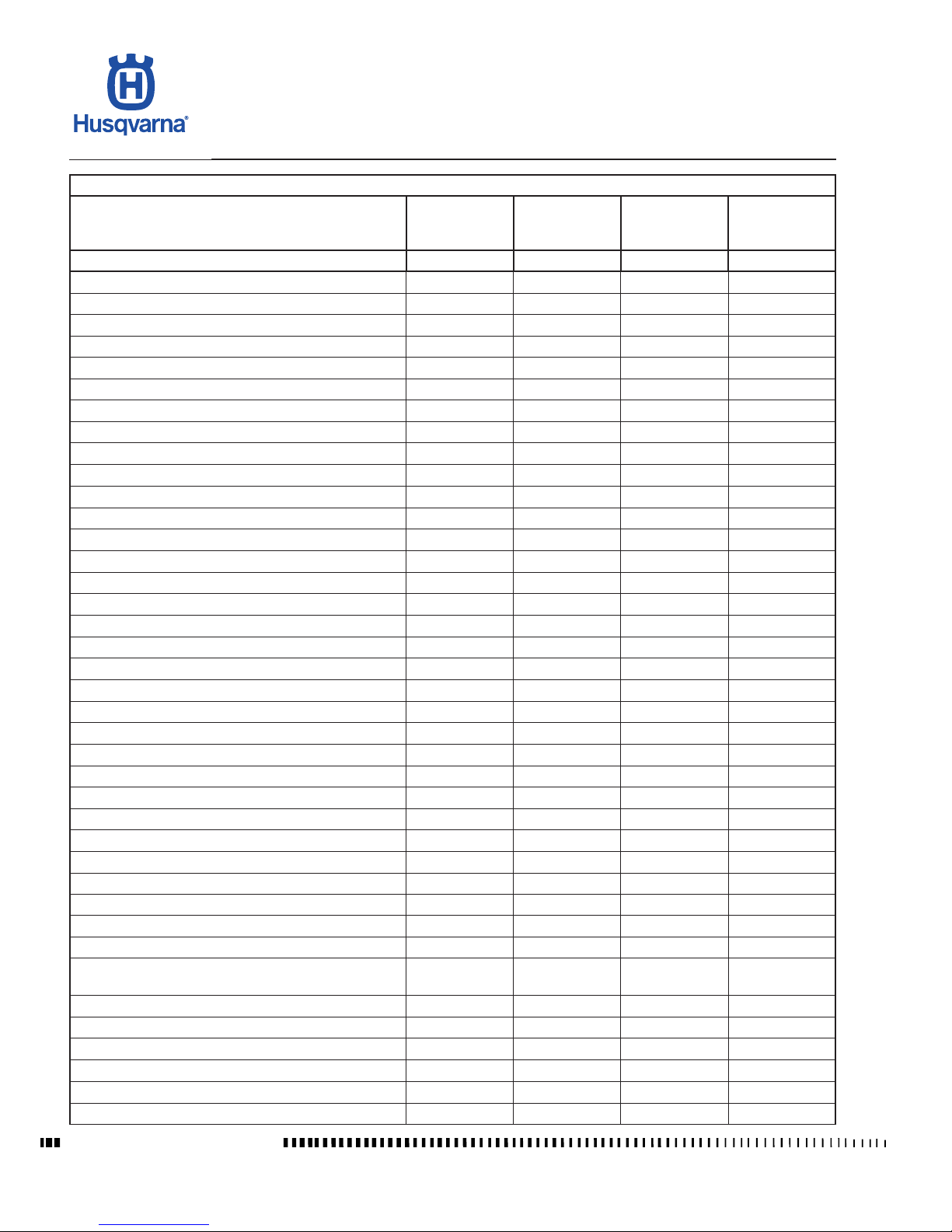
SCHEDULED MAINTENANCE CHART (TO BE CARRIED OUT AT THE HUSQVARNA DEALER)
TE 250R / TE 310R
STANDARD MOTORCYCLE, FOR ROAD USE
(DERATED)
AFTER FIRST
1000 KM
EVERY 5000 KM EVERY 10000 KM
REPLACE AS
REQUIRED
PART
SERVICE COUPON SERVICE COUPON SERVICE COUPON
VALVES
C (•) C (•) S
VALVE SPRINGS C X
TIMING CHAIN
S
TIMING CHAIN SLIDER C S
TIMING DRIVEN GEAR C X
TIMING DRIVE GEAR
C
TIMING CHAIN TENSIONER
C
INTAKE MANIFOLD AND CLAMPS C C S X
COMPLETE CYLINDER
C X
COMPLETE PISTON
S
COMPLETE CRANKSHAFT
S
CRANKCASE BEARINGS
S
CRANKSHAFT OIL SEAL
C X
ENGINE OIL AND OIL FILTER S S S
OIL PUMP
C
PRIMARY DRIVE GEAR PAIR
C X
CLUTCH HUB
C X
CLUTCH PLATES C C X
CLUTCH PRESSURE PLATE
C X
CLUTCH SPRINGS
C X
CLUTCH PUSHROD
C X
TRANSMISSION SPROCKET C C X
STARTER GEARS
C X
KICK START PEDAL
L
GEAR SHIFT PEDAL
C X
SPARK PLUG P S
AIR FILTER P, L P, L X
RADIATORS
C
WATER HOSES AND CLAMPS C C
RADIATORS TO WATER PUMP HOSE C C
CRANKSHAFT OIL SEAL C C
FOOTPEGS, PINS, SPRINGS
C X
REAR CHASSIS MNTG BOLTS, ENGINE MNTG
BOLTS
C C
SIDE STAND
C
CHAIN GUIDE ROLLER, BEARING C C X
STEERING HEAD, BOTTOM YOKE WITH STEM
L
FRONT FORK
R
HANDLEBAR MOUNTS WITH FASTENERS
C C
REAR SWINGING ARM BUSHING
C
Page 21
B.5
TE 250R - 310R 2013 I.E. / TE 310R 2013 I.E. USA
TC 250R 2013 - TC 250R 2013 I.E. USA
TXC 250R - 310R 2013 I.E. USA
Workshop Manual Ed. 07-2012
MAINTENANCE
SCHEDULED MAINTENANCE CHART (TO BE CARRIED OUT AT THE HUSQVARNA DEALER)
TE 250R / TE 310R
STANDARD MOTORCYCLE, FOR ROAD USE
(DERATED)
AFTER FIRST
1000 KM
EVERY 5000 KM EVERY 10000 KM
REPLACE AS
REQUIRED
PART
SERVICE COUPON SERVICE COUPON SERVICE COUPON
REAR CHAIN SLIDER
C C X
REAR SUSPENSION LINKAGE BUSHINGS
C X
CHAIN GUIDE/CHAIN GUARD
C C X
ROLLER CAGES, LINKAGE PINS OF REAR SUSP.
L
REAR SHOCK ABSORBER
C
COMPLETE THROTTLE CONTROL
C, L
COMPLETE CLUTCH CONTROL C R
THROTTLE CABLES C L X
FRONT BRAKE DISC C X
FRONT BRAKING SYSTEM FLUID C S
REAR BRAKE DISC
C X
REAR BRAKING SYSTEM FLUID C S
BRAKE PADS C C C X
MASTER CYLINDER TO BRAKE CALLIPER HOSES
C X
FUEL PIPES
C X
EXHAUST PIPE AND SILENCER
C X
WHEEL SPOKE TENSION
C C
WHEEL HUB BEARINGS
C X
REAR CHAIN SPROCKET C S
SPROCKET BOLT TIGHTENING C C C
SECONDARY DRIVE CHAIN C, L C, L C, L X
TORQUE OF NUTS AND BOLTS
C C
LÉGENDE:
S: REMPLACEMENT
C: CONTRÔLE
(•): CONTRÔLE JEU
P: NETTOYAGE
R: CONTRÔLE TECHNIQUE
L: GRAISSAGE/LUBRIFICATION
REMARQUES:
- REMPLACER LES JOINTS À CHAQUE DÉPOSE
- REMPLACER LA VISSERIE SI ENDOMMAGÉE
- APRÈS CHAQUE PARCOURS SUR TERRAIN BOUEUX OU SUR SABLE, FAIRE UN CONTRÔLE GÉNÉRAL
Page 22
B.6
TE 250R - 310R 2013 I.E. / TE 310R 2013 I.E. USA
TC 250R 2013 - TC 250R 2013 I.E. USA
TXC 250R - 310R 2013 I.E. USA
MAINTENANCE
Workshop Manual Ed. 07-2012
SCHEDULED MAINTENANCE CHART
(TO BE CARRIED OUT AT THE HUSQVARNA DEALER)
TC 250R
RACING MOTORCYCLE, FOR RACING
USE: FULL POWER RATING
EVERY 2,5 h
EVERY 5 h
EVERY 10 h
EVERY 20 h
EVERY 30 h
EVERY 40 h
EVERY 50 h
EVERY 60 h
EVERY 70 h
EVERY 80 h
EVERY 90 h
EVERY 100 h
REPLACE AS
REQUIRED
PART
CHECK
CHECK
SERVICE
COUPON
SERVICE
COUPON
SERVICE
COUPON
SERVICE
COUPON
SERVICE
COUPON
SERVICE
COUPON
SERVICE
COUPON
SERVICE
COUPON
SERVICE
COUPON
SERVICE
COUPON
AIR FILTER
P,L
REAR CHASSIS MNTG BOLTS,
ENGINE MNTG BOLTS
C
WHEEL SPOKE TENSION C
SPROCKET BOLT TIGHTENING C
TORQUE OF NUTS AND BOLTS C
COOLANT C X,
*
BRAKE PADS C X
REAR CHAIN SPROCKET C X
HANDLEBAR MOUNTS AND FASTEN-
ERS
C
REAR SWINGING ARM BUSHING L
REAR SUSPENSION LINKAGE BUSH-
INGS
L
CHAIN GUIDE/CHAIN GUARD C X
SWINGING ARM AXLE ROLLER CAGES L
ROLLER CAGES, LINKAGE PINS OF
REAR SUSP.
L
COMPLETE THROTTLE CONTROL C, L
EXHAUST PIPE AND SILENCER C X
FUEL PIPES C S X
SECONDARY DRIVE CHAIN C, L X
KICK START PEDAL L
GEAR SHIFT PEDAL C
RADIATORS C
WATER HOSES AND CLAMPS C
RADIATORS TO WATER PUMP HOSE C
FOOTPEGS, PINS, SPRINGS C X
STEERING HEAD, BOTTOM YOKE
WITH STEM
L
REAR CHAIN SLIDER C X
FRONT BRAKE DISC C S X
REAR BRAKE DISC C S X
CHAIN GUIDE ROLLER, BEARINGS C
COMPLETE CLUTCH CONTROL
R (#)
Page 23
B.7
TE 250R - 310R 2013 I.E. / TE 310R 2013 I.E. USA
TC 250R 2013 - TC 250R 2013 I.E. USA
TXC 250R - 310R 2013 I.E. USA
Workshop Manual Ed. 07-2012
MAINTENANCE
SCHEDULED MAINTENANCE CHART
(TO BE CARRIED OUT AT THE HUSQVARNA DEALER)
TC 250R
RACING MOTORCYCLE, FOR RACING
USE: FULL POWER RATING
EVERY 2,5 h
EVERY 5 h
EVERY 10 h
EVERY 20 h
EVERY 30 h
EVERY 40 h
EVERY 50 h
EVERY 60 h
EVERY 70 h
EVERY 80 h
EVERY 90 h
EVERY 100 h
REPLACE AS
REQUIRED
PART
CHECK
CHECK
SERVICE
COUPON
SERVICE
COUPON
SERVICE
COUPON
SERVICE
COUPON
SERVICE
COUPON
SERVICE
COUPON
SERVICE
COUPON
SERVICE
COUPON
SERVICE
COUPON
SERVICE
COUPON
THROTTLE CABLES C X
FRONT BRAKING SYSTEM FLUID S
REAR BRAKING SYSTEM FLUID S
MASTER CYLINDER TO BRAKE CALLI-
PER HOSES
C X
WHEEL HUB BEARINGS C
ENGINE OIL AND FILTER S
PLUG S
VALVES C (•) S
VALVE SPRINGS, ROCKER ARMS AND
PLATES
C
TIMING CHAIN / TIMING CHAIN SLIDER C
TIMING CHAIN GEARS C
TIMING CHAIN TENSIONER C
OIL PUMP C X
CRANKSHAFT OIL SEALS S
PISTON S
CYLINDER S
CLUTCH HUB C X
CRANKCASE BEARINGS S
CRANKSHAFT S
PRIMARY DRIVE GEAR PAIR C X
LEGEND:
h: HOURS
P: CLEAN
L: GREASE/LUBRICATE
C: CHECK
R: OVERHAUL
S: REPLACE
(•): CHECK CLEARANCE
*
: CHANGE AND/OR ADD IF NECESSARY
NOTES:
- REPLACE GASKETS AND SEALS AFTER EACH REMOVAL
- REPLACE SCREWS AND BOLTS IF DAMAGED
- PERFORM A GENERAL INSPECTION AFTER RIDING ON MUDDY OR SANDY TERRAIN
Page 24

Page 25

C.1
TE 250R - 310R 2013 I.E. / TE 310R 2013 I.E. USA
TC 250R 2013 - TC 250R 2013 I.E. USA
TXC 250R - 310R 2013 I.E. USA
C
Workshop Manual Ed. 07-2012
TROUBLESHOOTING
Section
Page 26

C.2
TE 250R - 310R 2013 I.E. / TE 310R 2013 I.E. USA
TC 250R 2013 - TC 250R 2013 I.E. USA
TXC 250R - 310R 2013 I.E. USA
TROUBLESHOOTING
Workshop Manual Ed. 07-2012
ENGINE
Trouble Cause Remedy
Engine does not start or Insufcient compression
has starting trouble 1. Piston seized Replace
2. Connecting rod small or big end seized Replace
3. Worn piston rings Replace
4. Worn cylinder Replace
5. Cylinder head loosely tightened Tighten
6. Head gasket leaking Replace
7. Spark plug loose Tighten
8. Incorrect valve clearances Adjust
9. Weak or seized valve springs Replace
10. Seized valves Replace
Weak or no spark
1. Spark plug faulty Replace
2. Fouled or wet spark plug Clean or dry
3. Spark plug electrode gap too wide Adjust
4. Ignition coil faulty Replace
5. High-tension cables open circuit or shorted Check
6. Electronic control unit faulty Replace
7. Right-hand switch faulty (TE - TXC) Replace
Engine stalls 1. Fouled spark plug Clean
easily 2. Electronic control unit faulty Replace
3. Carburettor jets clogged Clean
4. Low idle Adjust
Engine is noisy Noise seems to come from piston
1. Too much piston-to-cylinder clearance Replace
2. Worn piston rings or piston grooves Replace
3. Too much carbon build-up in
combustion chamber or on piston crown Clean
4. Valve clearances too large Adjust
5. Weak or seized valve springs Replace
6. Worn timing chain Replace
7. Incorrect timing chain tension Adjust
Noise seems to come from crankshaft
1. Worn main bearings Replace
2.
Connecting rod big end has too much side clearance or end oat
Replace
3. Crankshaft gear damaged Replace
4. Crankshaft locknut loose Tighten
Noise seems to come from the clutch
1. Worn plates Replace
2.
Too much clearance between clutch housing and friction plates
Replace
Noise seems to come from gearbox
1. Worn gears Replace
2. Worn gear grooves Replace
Noise seems to come 1. Chain stretched (worn) or improperly adjusted Replace or adjust
from secondary drive 2. Worn transmission sprocket and rear chain sprocket Replace
chain
Page 27

C.3
TE 250R - 310R 2013 I.E. / TE 310R 2013 I.E. USA
TC 250R 2013 - TC 250R 2013 I.E. USA
TXC 250R - 310R 2013 I.E. USA
Workshop Manual Ed. 07-2012
TROUBLESHOOTING
Trouble Cause Remedy
Clutch slips 1. Weak clutch springs Replace
2. Worn clutch plates Replace
Clutch is hard to operate 1. Uneven spring load Replace
2. Bent clutch plates Replace
Gears do not engage 1. Bent or seized shifter forks Replace
2. Worn gear ratchets Replace
3. Damaged shifter fork shafts Replace
Gear shift pedal
does not return to original position
1. Weak or broken selector return spring Replace
2. Worn shifter forks Replace
Transmission jumps out of gear 1. Worn sliding gear dogs Replace
2. Worn gear grooves Replace
3. Worn dog slots in gears Replace
4. Worn selector shaft splines Replace
5. Damaged shifter fork shafts Replace
Engine has low power 1. Dirty air lter Clean
2. Poor fuel quality Replace
3. Intake coupling loose Tighten
4. Spark plug electrode gap too wide Adjust
5. Insufcient compression Identify cause
6. Incorrect valve clearances Adjust
7. Valve seats or guides faulty Replace
8. Weak or seized valve springs Replace
Engine overheats 1. Combustion chamber and/or piston crown fouled
with carbon deposits Clean
2. Insufcient oil in engine or
wrong oil Top up or change
3. Obstructions blocking air ow on radiator Clean
4. Cylinder head gasket leaking Replace
5. Clutch slips Adjust
6. Cooling fan faulty (TE-TXC) Replace the fan
7. Faulty thermostatic valve (TE-TXC) Replace the valve
8. Faulty fan thermal switch Replace
Page 28

C.4
TE 250R - 310R 2013 I.E. / TE 310R 2013 I.E. USA
TC 250R 2013 - TC 250R 2013 I.E. USA
TXC 250R - 310R 2013 I.E. USA
TROUBLESHOOTING
Workshop Manual Ed. 07-2012
CHASSIS
Trouble Cause Remedy
Handlebar turns hard 1. Insufcient tyre pressure Inate
2. Bearing adjuster ring nut or steering stem nut overtightened Adjust
3. Bent steering stem Replace bottom yoke
4. Worn or seized steering bearings Replace
Handlebar vibration 1. Bent fork legs Replace
2. Bent front wheel axle Replace
3. Warped chassis Replace
4. Bent front wheel rim Replace
5. Worn front wheel bearings Replace
Damping is 1. Too much oil in fork legs Remove excess oil
too hard 2. Fork oil viscosity too high Change
3. Overinated tyres Deate
4. Improperly set rear shock absorber Adjust
Damping is 1. Insufcient oil in fork legs Top up
too soft 2. Fork oil viscosity too low Change
3. Weak fork springs Replace
4. Weak rear shock absorber spring Replace
5. Improperly set rear shock absorber Adjust
(Front / rear) wheel 1. Bent wheel rim Replace
shakes 2. Worn wheel hub bearings Replace
3. Incorrect spoke tension Adjust
4. Wheel axle nut loose Tighten
5. Worn rear swinging arm bearings Replace
6. Improperly adjusted chain tensioners Adjust
7. Improperly balanced wheel Balance
Rear suspension is 1. Worn link rod spacers or bearings Replace
noisy 2. Worn shock absorber ball joints Replace
3. Shock absorber faulty Replace
Poor braking 1. Air in brake system Bleed
(front and rear) 2. Insufcient uid in tank Top up
3. Worn brake pad and/or disc Replace
4. Damaged disc Replace
5. Improperly adjusted brake pedal Adjust
6. Water in brake system Change uid
Page 29

C.5
TE 250R - 310R 2013 I.E. / TE 310R 2013 I.E. USA
TC 250R 2013 - TC 250R 2013 I.E. USA
TXC 250R - 310R 2013 I.E. USA
Workshop Manual Ed. 07-2012
TROUBLESHOOTING
ELECTRICAL SYSTEM (see also Section M)
Trouble Cause Remedy
Spark plug fouls 1. Dirty air lter Clean
easily 2. Worn piston rings Replace
3. Worn piston or cylinder liner Replace
Spark plug electrodes 1. Spark plug electrode gap too close Adjust
overheat 2. Heat rating too high Replace with recommended
spark plug
Generator does not charge or 1.
Cables running to voltage regulator improperly connected or
Connect correctly or
is not providing enough charge shorted replace
2. Voltage regulator faulty Replace
3. Generator coil faulty Replace
Generator overcharges battery 1. Voltage regulator faulty Replace
Battery does not hold charge 1. Battery terminals dirty Clean
(TE-TXC)
Starter motor 1. Battery is at Charge
does not start or slips 2. Control on R.H. switch faulty Replace
(TE-TXC) 3. Starter relay faulty Replace
4. Starter motor faulty Repair or replace
5. Worn starter gears Replace
6. Worn or damaged freewheel rollers Replace freewheel
Page 30

Page 31

D.1
TE 250R - 310R 2013 I.E. / TE 310R 2013 I.E. USA
TC 250R 2013 - TC 250R 2013 I.E. USA
TXC 250R - 310R 2013 I.E. USA
D
Workshop Manual Ed. 07-2012
SETTINGS AND ADJUSTMENTS
Section
Page 32

D.2
TE 250R - 310R 2013 I.E. / TE 310R 2013 I.E. USA
TC 250R 2013 - TC 250R 2013 I.E. USA
TXC 250R - 310R 2013 I.E. USA
SETTINGS AND ADJUSTMENTS
Workshop Manual Ed. 07-2012
Sommario
Saddle removal.............................................................................................D.4
Tank removal ................................................................................................D.4
Valve clearance adjustment .........................................................................D.6
Adjustment throttle cable ..............................................................................D.9
Idle adjustment .............................................................................................D.9
Clutch plate replacement ............................................................................D.10
Hydraulic clutch lever adjustment and uid level check ............................D.11
Front brake lever adjustment and uid level check ....................................D.12
Rear brake pedal position adjustment ........................................................D.13
Rear brake pedal free play adjustment.......................................................D.14
Rear brake uid level check .....................................................................D.14
Engine oil level check .................................................................................D.15
Engine oil replacement and mesh lters-lter cartridge cleaning or replacement
...D.16
Coolant level check ....................................................................................D.17
Coolant replacement ..................................................................................D.17
Air lter check (TC)
.....................................................................................D.18
Air lter cleaning .........................................................................................D.18
Air lter check (TE - TXC)
...........................................................................D.19
Air lter cleaning .........................................................................................D.19
Assembly ....................................................................................................D.20
Secondary drive chain adjustment
.............................................................D.21
Chain lubrication
.........................................................................................D.22
Disassembling and cleaning
.......................................................................D.22
Washing a chain without O-rings (TC)
........................................................D.22
Lubricating a chain without O-rings (TC) ...................................................D.22
Washing the chain with OR (TE - TXC)
......................................................D.22
Lubricating an O-ring chain
........................................................................D.22
Suspension setup according to track condition
..........................................D.23
Shock absorber adjustment
........................................................................D.24
Shock absorber spring preload adjustment ................................................D.25
Shock absorber compression and rebound damping adjustment
.............D.26
Shock absorber springs ....
........................................................................D.26
KAYABA front fork adjustment
....................................................................D.27
Steering bearing clearance adjustment
......................................................D.28
Steering angle adjustment .........................................................................D.28
Supply hose check
.....................................................................................D.29
Exhaust system check
................................................................................D.30
Page 33

D.3
TE 250R - 310R 2013 I.E. / TE 310R 2013 I.E. USA
TC 250R 2013 - TC 250R 2013 I.E. USA
TXC 250R - 310R 2013 I.E. USA
H11269
TE
H11270
TXC
H11271
TC
Workshop Manual Ed. 07-2012
SETTINGS AND ADJUSTMENTS
Page 34
D.4
TE 250R - 310R 2013 I.E. / TE 310R 2013 I.E. USA
TC 250R 2013 - TC 250R 2013 I.E. USA
TXC 250R - 310R 2013 I.E. USA
H02181
5
3
6
H02183
4
5
SETTINGS AND ADJUSTMENTS
Workshop Manual Ed. 07-2012
Saddle removal
Turn the rear xing (1) counter clockwise, remove it and extract the saddle.
Tank removal
During the fuel tank removal operations, pay particular attention to
the couplings of the fuel hose on the pump body and on the throttle
body in order to prevent possible breakage / damages to the parts.
Remove the screws (1) and the side panels.
Remove the tank retaining screw (2).
(TE-TXC)
Close the two taps (3) and (4) and connect the hose (5).
Disconnect connector (6) of the reserve sensor.
Page 35
D.5
TE 250R - 310R 2013 I.E. / TE 310R 2013 I.E. USA
TC 250R 2013 - TC 250R 2013 I.E. USA
TXC 250R - 310R 2013 I.E. USA
H09060
TC
7
H09061
TC
8
9
H11273
8
9
7
TE - TXC
H11274
10
Workshop Manual Ed. 07-2012
SETTINGS AND ADJUSTMENTS
Lift the tank and disconnect the fuel pump connector (7) from the main wiring
harness.
Disconnect the supply hose (8) from the outlet tting (9) on the fuel pump, located
in the rear bottom section of the tank.
Remove the tank (10) together with the scoops.
Page 36
D.6
TE 250R - 310R 2013 I.E. / TE 310R 2013 I.E. USA
TC 250R 2013 - TC 250R 2013 I.E. USA
TXC 250R - 310R 2013 I.E. USA
H10948
1
2
3
4
H10949
6
7
5
H10950
8
8
9
SETTINGS AND ADJUSTMENTS
Workshop Manual Ed. 07-2012
Valve clearance adjustment
Remove saddle and tank as outlined in the relevant paragraphs.
- Remove the connector (1) from the coil (2).
- Loosen the two screws (3), remove coil (2) and retaining bracket (4), and
then remove the spark plug.
NOTE: During retting, check that the gasket (5) is correctly positioned;
the reference lug (6) must correspond with the retaining bracket
(4) gap (7).
Loosen the four screws (8) of the head cover and remove the head cover (9).
Page 37
D.7
TE 250R - 310R 2013 I.E. / TE 310R 2013 I.E. USA
TC 250R 2013 - TC 250R 2013 I.E. USA
TXC 250R - 310R 2013 I.E. USA
H10951
10
10
H10952
10
10
Workshop Manual Ed. 07-2012
SETTINGS AND ADJUSTMENTS
Engage the 2nd gear and push and pull the motorcycle back and forth to bring
the piston to Top Dead Centre. In this condition, the engraved reference marks
(10) on the gears of the camshafts are positioned on the same axle although
they are diametrically opposed.
INTAKE OUTLET
Page 38

D.8
TE 250R - 310R 2013 I.E. / TE 310R 2013 I.E. USA
TC 250R 2013 - TC 250R 2013 I.E. USA
TXC 250R - 310R 2013 I.E. USA
H10953
H10954
H10955
H10956
SETTINGS AND ADJUSTMENTS
Workshop Manual Ed. 07-2012
Use a thickness gauge to make sure that the clearance is equal to 0.15 mm for
the INTAKE side (Figure “A”) and 0.20 mm for the OUTLET side (Figure “B”).
If not so, remove the shim from under the valve bucket and measure its thickness.
Depending on what you nd, replace the shim with a new shim with the required
thickness to achieve correct clearance (replacement shims are available in a
1.60 mm to 2.60 mm thickness range, in 0.05 mm increments).
Check valve clearances again. If clearances are correct, ret the parts you have
removed reversing the disassembly procedure.
For camshaft disassembly and reassembly, see Section “F” Engine disassembly
and Section “H” Engine assembly.
FIGURE A
INTAKE
FIGURE A
INTAKE
FIGURE B
OUTLET
FIGURE B
OUTLET
Page 39
D.9
TE 250R - 310R 2013 I.E. / TE 310R 2013 I.E. USA
TC 250R 2013 - TC 250R 2013 I.E. USA
TXC 250R - 310R 2013 I.E. USA
H11275
1
2
3
5
5
4
4
H11276
1
Workshop Manual Ed. 07-2012
SETTINGS AND ADJUSTMENTS
Adjustment throttle cable
To check the correct adjustment of the throttle operate as follows:
- Remove rubber caps (1);
- By moving the opening cable (2) back and forth, check that free play is 3
mm;
- By moving the closing cable (3) back and forth, check that free play is 1 mm;
- If it does not happen, loosen the nut (4) and appropriately turn the adjuster
screw (5);
(loosen it to decrease clearance, tighten it to increase it);
- After adjustment block the nut (4).
Operation with damaged throttle cable could result in an unsafe
riding condition.
Exhaust gas contains poisonous carbon monoxide. Never run the
engine indoors.
To replace the cables, you will need to remove the fuel tank as described in the
relevant paragraph.
Idle adjustment
Adjust the carburetor with warm engine and with the throttle control in closed
position. Proceed as follows:
- turn the knob (1) on the right side of the throttle body of about 34 clicks from
the fully closed position, checking with the suitable device that revs are of
about 1,950 RPM (turn clockwise to increase the speed and counter clockwise
to reduce it).
Page 40
D.10
TE 250R - 310R 2013 I.E. / TE 310R 2013 I.E. USA
TC 250R 2013 - TC 250R 2013 I.E. USA
TXC 250R - 310R 2013 I.E. USA
H11101
SETTINGS AND ADJUSTMENTS
Workshop Manual Ed. 07-2012
Clutch plate replacement
This procedure can be performed with the motorcycle leaning to the left - there
is no need to drain engine oil.
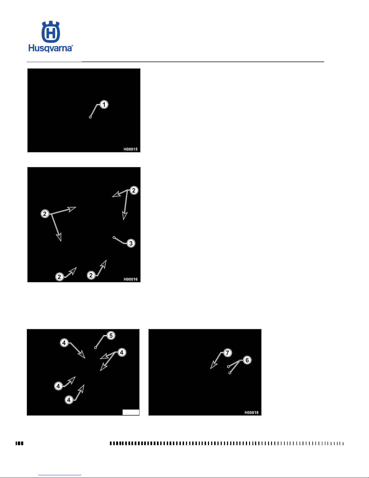
- Remove the brake pedal (1).
- Remove the six retaining screws (2) and the clutch cover (3).
- Using an 8 mm wrench, unscrew the six screws (4) securing the clutch springs.
Remove springs, pressure plate (5) with bearing (6) and clutch actuator plate
(7).
Page 41
D.11
TE 250R - 310R 2013 I.E. / TE 310R 2013 I.E. USA
TC 250R 2013 - TC 250R 2013 I.E. USA
TXC 250R - 310R 2013 I.E. USA
H11277
B
2
1
1
3
C
A
D
H11278
4mm (0,16 in.)
Workshop Manual Ed. 07-2012
SETTINGS AND ADJUSTMENTS
- Remove the plates (8), lubricate the new plates with engine oil and install
them (always start with a friction plate).
Ret clutch actuator plate, bearing and pressure plate.
Tighten the spring screws gradually in a cross pattern (8 Nm - 0.8 Kgm - 5.8 ft/lb).
When retting the clutch cover (8 Nm - 0.8 Kgm - 5.8 ft/lb), check gasket for
wear and replace as required.
For additional information on assembly procedures, see Section
"H" Engine assembly.
Hydraulic clutch lever adjustment and uid level check
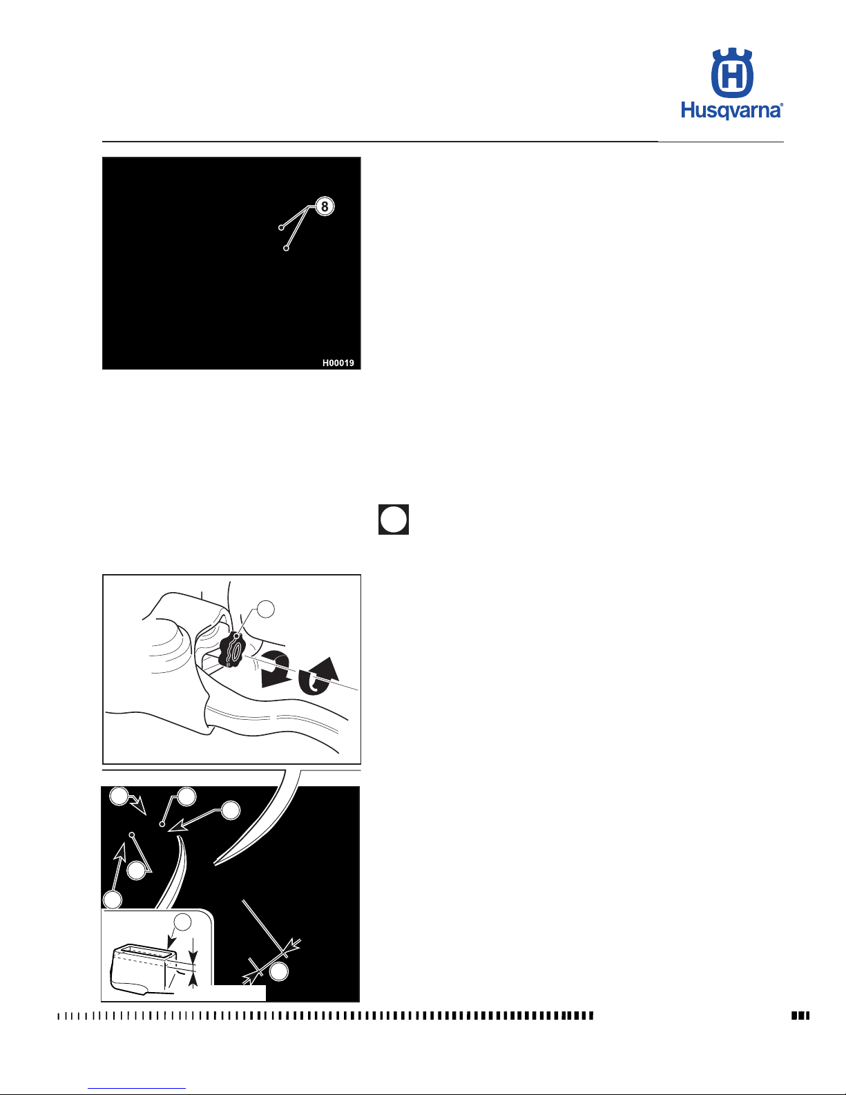
Free play (A) must be at least 0,39 in. (10 mm).
The lever position can be adjusted to suit the rider hand size.
To decrease the lever distance from the handgrip, rotate the adjuster (B)
CLOCKWISE.
To increase the lever distance from the handgrip, rotate the adjuster (B) COUNTER CLOCKWISE.
Fluid level is checked as follows:
- Remove screws (1), cover (2) and rubber diaphragm from the control;
- Keep the control cylinder (3) in a horizontal position and make sure that uid
level has not dropped lower than 4 mm (0.16 in.) below the upper edge (D)
of master cylinder body;
- If needed, top up with the uid specied in the LUBRICANT CHART included
in Section "A".
Ret any parts you have removed.
Periodically check the connecting hose (see “Scheduled Maintenance Chart”);
if hose (C) is worn or cracked, its replacement is advised.
Page 42
D.12
TE 250R - 310R 2013 I.E. / TE 310R 2013 I.E. USA
TC 250R 2013 - TC 250R 2013 I.E. USA
TXC 250R - 310R 2013 I.E. USA
H09070
2
A
+
B
_
H09071
1
H11279
1
a
SETTINGS AND ADJUSTMENTS
Workshop Manual Ed. 07-2012
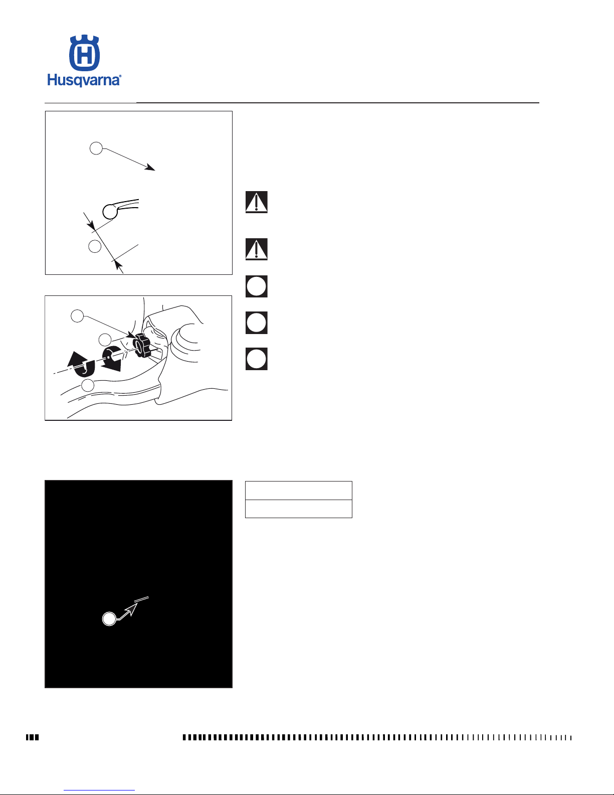
A: to increase clearance
B: to decrease clearance
Front brake lever adjustment and uid level check
The adjuster (1) located on the control lever, allows adjusting of the free play
(a). Free play (a) must be at least 0,39 in. (10 mm).
The level of the uid in master cylinder reservoir must never be below the minimum value (2), which can be checked from the inspection window on the rear of
the master cylinder body. A decrease of the uid level will let air into the system,
hence an extension of the lever stroke.
If the brake lever feels mushy when pulled, there may be air in the
brake line or the brake may be defective: CHECK THE BRAKING
SYSTEM (see Section "L").
Too much brake lever free play may reduce braking action: CHECK
BRAKE PAD THICKNESS (see Section "L").
Do not spill brake uid onto any painted surface or lens (for example
lights lens).
Do not mix two brands of uid. Completely change the brake uid
in the brake system if you wish to switch to another uid brand.
Brake uid may cause irritation. Avoid contact with skin or eyes.
In case of contact, ush thoroughly with water and call a doctor if
your eyes were exposed.
Page 43
D.13
TE 250R - 310R 2013 I.E. / TE 310R 2013 I.E. USA
TC 250R 2013 - TC 250R 2013 I.E. USA
TXC 250R - 310R 2013 I.E. USA
Workshop Manual Ed. 07-2012
SETTINGS AND ADJUSTMENTS
Rear brake pedal position adjustment
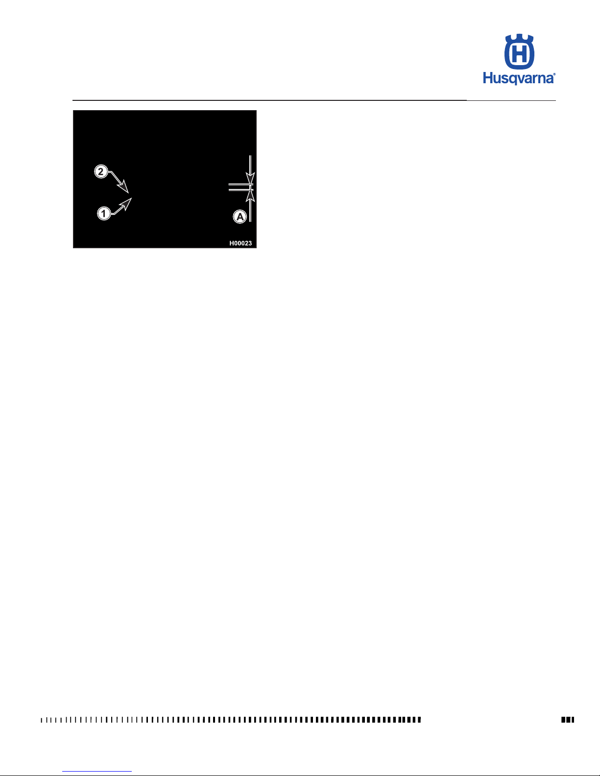
The position of the rear brake pedal with respect to the footrest may be adjusted
according to individual needs.
For adjusting, proceed as follows:
- Loosen the screw (1).
- Turn the cam (2) in order to raise or lower the brake pedal within the range
available (A).
- When nished, tighten the screw (1).
Once this operation is completed, it is necessary to check/adjust the free play
of the pedal as well, according to the instructions below.
Page 44
D.14
TE 250R - 310R 2013 I.E. / TE 310R 2013 I.E. USA
TC 250R 2013 - TC 250R 2013 I.E. USA
TXC 250R - 310R 2013 I.E. USA
SETTINGS AND ADJUSTMENTS
Workshop Manual Ed. 07-2012
C: to increase clearance
D: to decrease clearance
Rear brake pedal free play adjustment
The rear brake pedal should have 5 mm free play (B) before the brake begins
to bite. Should this not happen, operate as follows:
- Loosen the nut (3);
- Operate the master cylinder linkage (4) to increase or decrease free play;
- Tighten the nut (3) at the end of the operation.
When the free play requirement is not met, the brake pads will be
subjected to an early wear that may lead to TOTAL BRAKE INEFFECTIVENESS.
If the brake pedal feels mushy when pulled, there may be air in the
brake line or the brake may be defective. CHECK THE BRAKING
SYSTEM (see Section L).
Rear brake uid level check
Level (A) must be between the MIN and MAX notches visible on the master
cylinder reservoir.
Page 45
D.15
TE 250R - 310R 2013 I.E. / TE 310R 2013 I.E. USA
TC 250R 2013 - TC 250R 2013 I.E. USA
TXC 250R - 310R 2013 I.E. USA
Workshop Manual Ed. 07-2012
SETTINGS AND ADJUSTMENTS
Engine oil level check
Keeping the motorcycle level and upright, check the oil level through the inspection window (1) on the right crankcase.
Make sure level is up to window midline (1).
To top up, remove the ller cap (2).
Have this operation made with warmed-up engine.
Be careful not to touch hot engine oil.
Page 46
D.16
TE 250R - 310R 2013 I.E. / TE 310R 2013 I.E. USA
TC 250R 2013 - TC 250R 2013 I.E. USA
TXC 250R - 310R 2013 I.E. USA
H00977-1
A
7
8
6
H02335
3c
3a
3b
H02336
310
4
250
SETTINGS AND ADJUSTMENTS
Workshop Manual Ed. 07-2012
Engine oil replacement and mesh lters-lter cartridge cleaning or replacement
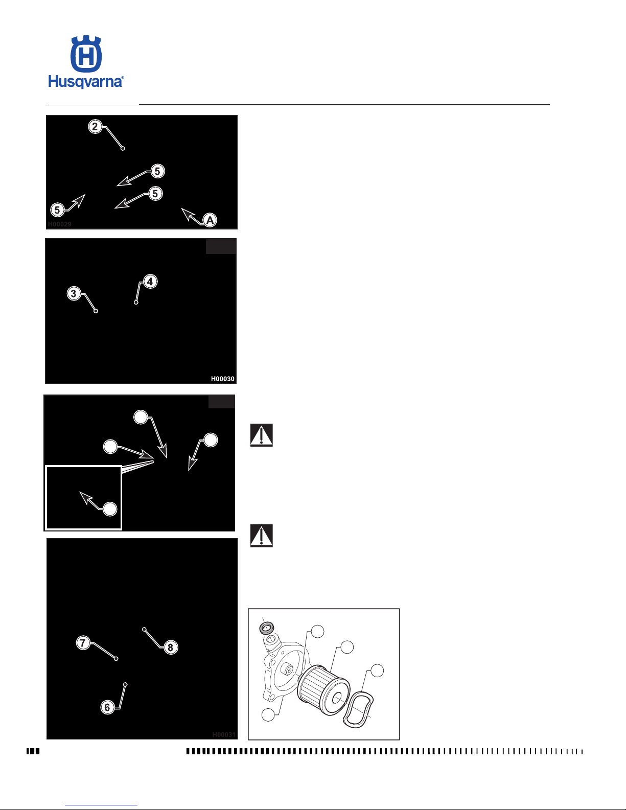
Drain the oil with WARM ENGINE; proceed as follows:
- Remove the oil ller cap (2).
- The oil sump guard (A) may be left in place. However, the procedure will be
easier with the guard removed.
- Place an oil drain pan under the engine.
(TE-TC-TXC 250)
- Remove oil drain plug (3) and lter (4), drain the oil and clean the plug magnet.
- Wash the lter (4) with petrol and ret it into its seat.
(TE 310)
- loosen tie (3a) without disconnecting tube (3b);
- unscrew hose tail (3c), remove mesh lter (4) and drain the used oil.
- Unscrew the screws (5) and remove cover (6) together with lter (7).
- Change the lter (7) and ret the assembly making sure to t the Belleville
washer (8) in the correct position.
(TE-TC-TXC 250)
- Ret the drain plug (3) (25 Nm - 2.5 Kgm - 33.89 ft/lb) and the oil sump guard
(A).
(TE 310)
- Reassemble tting (3c), screw clamp (3a), and ret the engine cover (A).
- Fill with the specied quantity of oil.
For recommended oil type and quantity, see "Capacities" table in Section
"A".
Be careful not to touch hot engine oil.
WARNING When assembling lter to cover, make sure to t the lter
oil seal (A) rst onto the cover (6).
Page 47
D.17
TE 250R - 310R 2013 I.E. / TE 310R 2013 I.E. USA
TC 250R 2013 - TC 250R 2013 I.E. USA
TXC 250R - 310R 2013 I.E. USA
H02187
3
H09072
1
H11280
1
2
H11281
B
B
B
A
A
Workshop Manual Ed. 07-2012
SETTINGS AND ADJUSTMENTS
Coolant level check
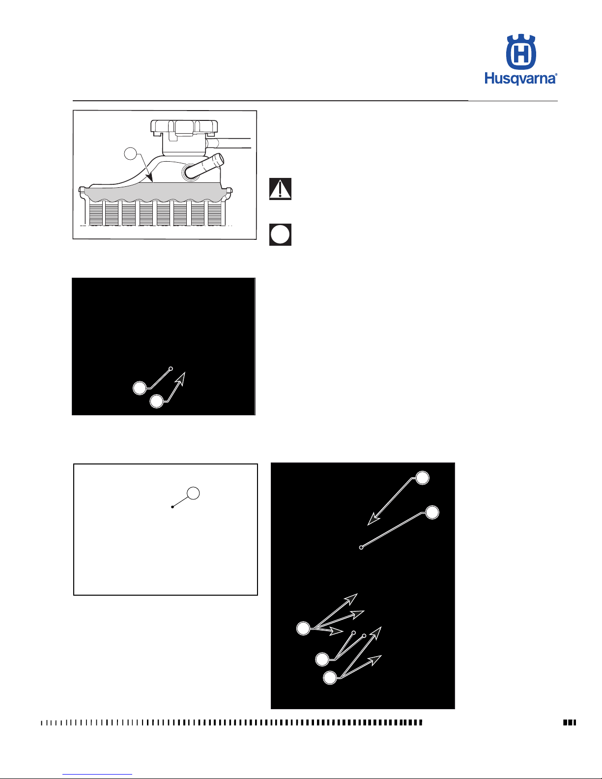
Check level (1) in right-hand radiator when engine is cold (place the motorcycle
so that it is perpendicular to the ground). The coolant should be approximately
0.39 in. above the cells.
The radiator cap features two locking positions: the rst one is for prior discharge
of pressure from the cooling system.
Avoid removing radiator cap when engine is hot, as coolant may
spout out and cause scalding.
Difculties may arise in eliminating coolant from painted surfaces.
If this occurs, wash off with water.
Coolant replacement
Place a vessel on the L.H. side of the cylinder, under the hose (1).
Loosen the clamp (2) on the hose (1) and detach the hose from the engine.
SLOWLY open the cap (3) of the right-hand radiator and lean the motorcycle to
the left to let the coolant drain into the vessel.
When nished, ret the hose (1) and secure it with the clamp (2).
Pour the necessary quantity of coolant in the radiator then warm up the engine
in order to eliminate any possible air bubbles.
Periodically check the connecting hoses (see “Scheduled Maintenance Chart”):
this will avoid coolant leakage and consequent engine seizure. If hoses (A) show
cracks, swelling or hardening due to sheaths desiccation, their replacement
shall be advisable.
Check the correct tightening of the clamps (B).
Page 48
D.18
TE 250R - 310R 2013 I.E. / TE 310R 2013 I.E. USA
TC 250R 2013 - TC 250R 2013 I.E. USA
TXC 250R - 310R 2013 I.E. USA
SETTINGS AND ADJUSTMENTS
Workshop Manual Ed. 07-2012
Air lter check (TC)
Turn the rear xing (1) counter clockwise, remove it and extract the saddle releasing it from the front retaining screw.
Remove the screw (3), remove the complete air lter (4) and separate lter (5)
from rear chassis (6).
Air lter cleaning
Wash the lter with a specic detergent (see "Capacities" table in Section A)
then dry it fully (wash lter with gasoline only in case of need). Plunge the lter
in special oil for lters (see "Capacities" table in Section A), then wring it to drain
superuous oil.
Do not use fuel or a low ash-point solvent to clean the ltering
element. A re or explosion could result.
Clean the ltering element in a well ventilated area and do not allow
sparks or ames anywhere near the working area.
Page 49
D.19
TE 250R - 310R 2013 I.E. / TE 310R 2013 I.E. USA
TC 250R 2013 - TC 250R 2013 I.E. USA
TXC 250R - 310R 2013 I.E. USA
Workshop Manual Ed. 07-2012
SETTINGS AND ADJUSTMENTS
Air lter check (TE - TXC)
Turn the rear xing (1) counter clockwise, remove it and extract the saddle releasing it from the front retaining screw.
Take out the battery (A) and leave it hanging on the side of the motorcycle.
Remove the screw (3), remove the complete air lter (4) and separate lter (5)
from intake silencer (6).
Air lter cleaning
Wash the lter with a specic detergent (see "Capacities" table in Section A)
then dry it fully (wash lter with gasoline only in case of need). Plunge the lter
in special oil for lters (see "Capacities" table in Section A), then wring it to drain
superuous oil.
Do not use fuel or a low ash-point solvent to clean the ltering
element. A re or explosion could result.
Clean the ltering element in a well ventilated area and do not allow
sparks or ames anywhere near the working area.
Page 50
D.20
TE 250R - 310R 2013 I.E. / TE 310R 2013 I.E. USA
TC 250R 2013 - TC 250R 2013 I.E. USA
TXC 250R - 310R 2013 I.E. USA
H09073
A
B
C
TE - TXC
TC
SETTINGS AND ADJUSTMENTS
Workshop Manual Ed. 07-2012
Assembly
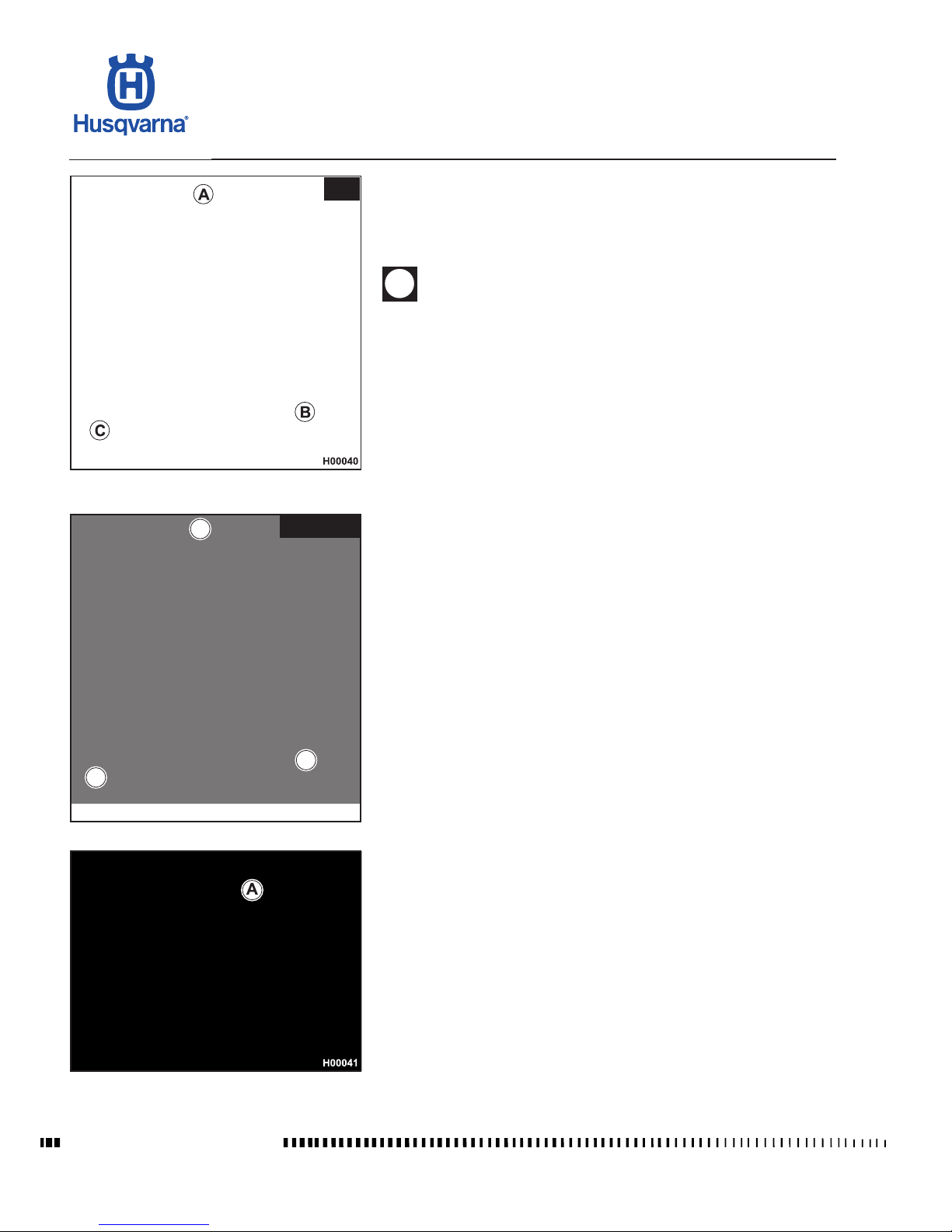
Grease the edge (C) of the lter face that goes into the housing to ensure proper
sealing. When retting the lter into its housing, make sure to position it with
the tab (A) pointing upwards and edge (B) at the left bottom corner of the lter
housing. Ret any parts you have removed.
An improperly positioned lter might let dirt or dust into the engine,
leading to early wear of piston rings and cylinder.
A = Upper side
B = Left-hand side
Page 51
D.21
TE 250R - 310R 2013 I.E. / TE 310R 2013 I.E. USA
TC 250R 2013 - TC 250R 2013 I.E. USA
TXC 250R - 310R 2013 I.E. USA
H09074
a
C
H09075
1
H09076
3
2
H09077
*
145
35
[mm]
REGOLAZIONE CATENA
Workshop Manual Ed. 07-2012
SETTINGS AND ADJUSTMENTS
Fig. A
Fig. B
Secondary drive chain adjustment
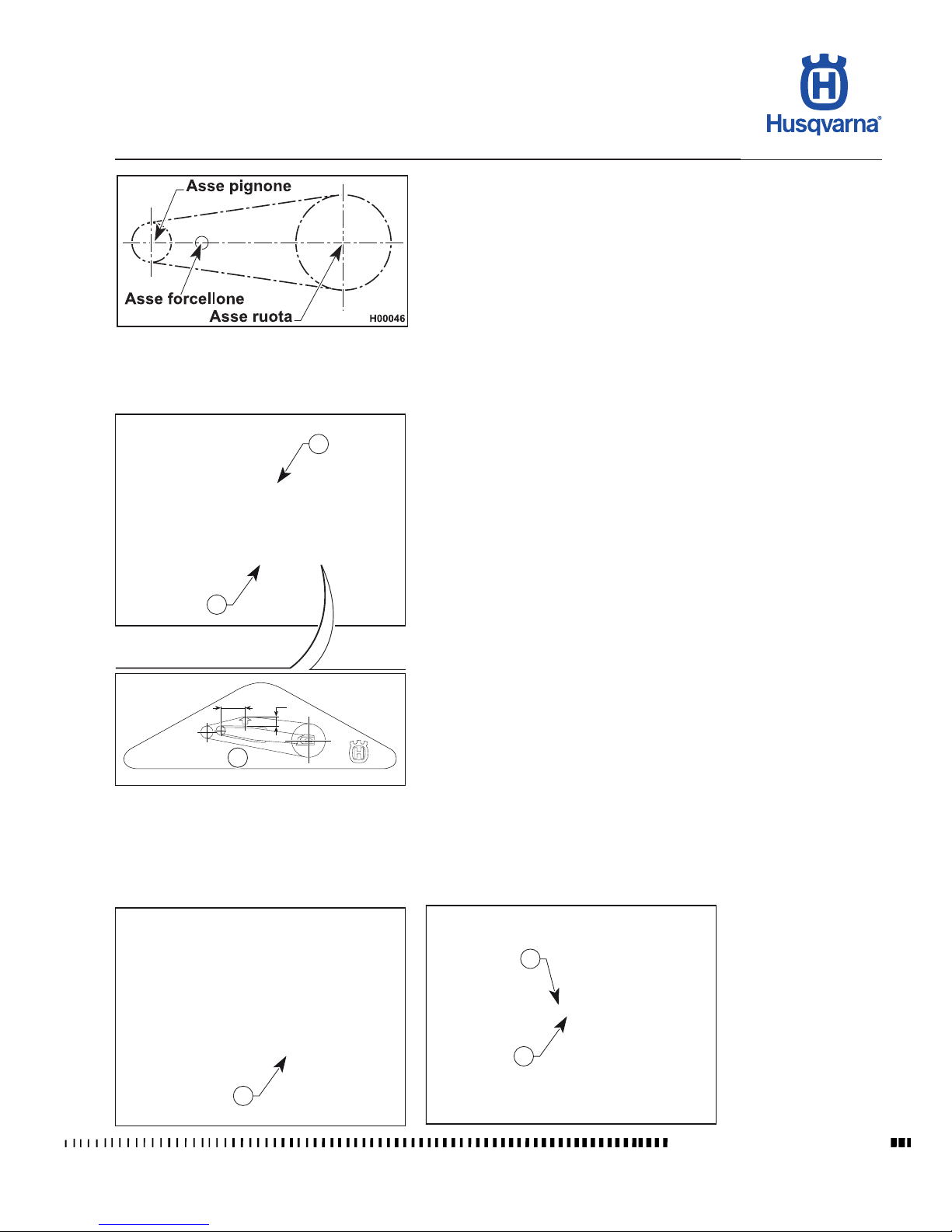
Chain should be checked, adjusted and lubricated as per the "Maintenance
Chart" (see Section B) to ensure safety and prevent excessive wear. If the chain
becomes badly worn or is poorly adjusted (i.e., if it is too loose or too taut), it
could escape from sprocket or break. To adjust chain tension, you need to lower
the rear end of the motorcycle so as to bring the axes of rotation of sprocket,
swinging arm and rear wheel into alignment as shown in gure "A", and then
turn the rear wheel three turns. In this condition, the chain should be neither
taut nor slack. (Fig. A).
Quick adjustment (Fig. B)
Insert, at a distance of 145 mm (5.7 in.) from the fork centre, a bushing (a) with
a 35 mm (1.37 in.) diameter (as an alternative, insert a spacer of the same
dimensions) and make sure that the lower arm (C) of the chain is slightly tight.
If it is not, proceed as follows:
- Loosen the wheel axle nut (1) on the right-hand side using a 27 mm socket
wrench;
- Loosen the check nuts (2) on both chain tensioners with a 12 mm wrench
and work the screws (3) until achieving the correct tension;
- When the adjustment is completed, tighten the check nuts (2) and the wheel
axle nut (1).
After any adjustment, always check wheel alignment and tighten wheel axle
securely (142.1 Nm - 14.5 Kgm - 104.8 ft/lb).
Asse pignone = Sprocket axis
Asse forcellone = Swinging arm axis
Asse ruota = Wheel axis
* : Chain adjustment
Page 52
D.22
TE 250R - 310R 2013 I.E. / TE 310R 2013 I.E. USA
TC 250R 2013 - TC 250R 2013 I.E. USA
TXC 250R - 310R 2013 I.E. USA
H09078
5
3
4
H11142
SETTINGS AND ADJUSTMENTS
Workshop Manual Ed. 07-2012
Chain lubrication
Lubricate the chain following these instructions.
Never use grease to lubricate the chain. Grease helps to accumulate
dust and mud, which act as abrasive and help to rapidly wear out
the chain, the front and rear sprockets.
Disassembling and cleaning
When particularly dirty, remove and clean the chain before lubrication. Proceed
as follows:
- Set a stand or a block under the engine and see that the rear wheel is lifted
from the ground.
- Remove: screws (1), sprocket guard (2), clip (3), master link (4) and chain
(5). To reassemble, reverse the above procedure.
Make sure that the chain is neither worn out nor damaged. If the rollers or the
links are damaged, replace the chain by following the instructions given in the
Scheduled Maintenance Chart. Ensure that the sprockets are not damaged.
Wash and clean the chain as described hereunder.
Washing a chain without O-rings (TC)
Wash using petroleum or naphtha. If you use fuel or especially trichloroethylene,
dry and lubricate the chain to avoid oxidisation.
Lubricating a chain without O-rings (TC)
After drying, dip the chain in Molybdenum Disulphide chain lubricant, if possible,
or in warm high-viscosity engine oil (if warmed up, oil will be more uid).
NOTE: As an alternative, you can use suitable spray lubricants.
Washing the chain with OR (TE - TXC)
Wash using oil, diesel oil, or parafn oil. Never use gasoline, tricloroetilene, or
solvents, as the OR may suffer damages.
Use instead special sprays for chains with OR.
Lubricating an O-ring chain
Lubricate all metallic and rubber (O-ring) elements using a brush and engine oil
with SAE 80-90 viscosity, inside and outside parts.
Assemble the master link clip (3) by setting the closed side facing the chain
direction of rotation, as shown in the gure.
The master link is the most critical safety part in the drive chain. Even
if the master links are reusable when in good conditions, for safety
purposes we advise using a new master link when reassembling
the chain.
Accurately adjust the chain as described on page D.18.
The chain lubricant shall NEVER get in contact with the tyres or the
rear brake disc.
Chain guide roller, chain guide roller, chain guide, chain slider
Check the wear of the above-mentioned elements and replace them
when necessary.
Check the chain guide alignment, and remember that a bent element
can cause chain early wear. In this case, chain might unwrap from
the sprocket.
Page 53

D.23
TE 250R - 310R 2013 I.E. / TE 310R 2013 I.E. USA
TC 250R 2013 - TC 250R 2013 I.E. USA
TXC 250R - 310R 2013 I.E. USA
Workshop Manual Ed. 07-2012
SETTINGS AND ADJUSTMENTS
Suspension setup according to track condition
Following are a few guidelines to nd the right suspension setup
for different types of terrain. Always start from the suspensions standard setting before making any change. Afterwards, increase or decrease the adjusting
clicks, one at a time.
HARD GROUND
Front fork: softer compression setting.
Shock absorber: softer compression setting.
For fast tracks, a softer compression and rebound setting both front and rear
will give more grip.
SANDY GROUND
Front fork: set compression harder, or replace the standard spring with a harder
spring and set the compression softer and the rebound harder.
Shock absorber: harder compression, and especially harder rebound settings.
Work on the spring preload to lower the motorcycle riding height (rear end).
MUDDY GROUND
Front fork: set compression harder, or replace the standard spring with a harder
spring.
Shock absorber: harder compression and rebound settings
or replace the standard spring with a harder spring. Work on the spring preload
to lift the motorcycle riding height (rear end). Changing the springs front and
rear is advised in order to compensate for increased motorcycle weight due to
caked-on mud.
NOTES
If the fork remains too soft or too hard no matter what setting you choose,
check oil level in the fork tubes, as it might be too low
or too high. Remember that the more oil you add, the more frequently you will
need to bleed the forks. If changes to suspension settings take no effect, check
the adjuster assemblies, as they might be stuck.
Standard settings, available replacement springs and adjusting procedures are
outlined in the following pages.
Page 54
D.24
TE 250R - 310R 2013 I.E. / TE 310R 2013 I.E. USA
TC 250R 2013 - TC 250R 2013 I.E. USA
TXC 250R - 310R 2013 I.E. USA
H02180
B
C
A
SETTINGS AND ADJUSTMENTS
Workshop Manual Ed. 07-2012
B: panel retaining screw axis
C: rear wheel axle height
Shock absorber adjustment
The rear shock absorber must be adjusted to suit rider weight and terrain conditions.
Proceed as follows:
1. Place the motorcycle on the stand and measure distance (A).
2. Sit on the motorcycle in normal riding position with full riding gear on.
3. Have someone else measure distance (A) again.
4. The difference between these two measurements is the distance the rear end
settles when the rider sits on the motorcycle (RIDER SAG). Recommended
rider sag is 100 mm with a cold shock absorber and 95 mm with a warm
shock absorber.
5. To achieve correct rider sag for your weight, adjust the spring preload of the
shock absorber (see relevant paragraph).
Page 55
D.25
TE 250R - 310R 2013 I.E. / TE 310R 2013 I.E. USA
TC 250R 2013 - TC 250R 2013 I.E. USA
TXC 250R - 310R 2013 I.E. USA
H09079
1
H09080
2
2
3
H09081
4
5
6
H09082
4
5
A
Workshop Manual Ed. 07-2012
SETTINGS AND ADJUSTMENTS
The standard length of the preloaded spring is
as follows:
TC - TXC: A= 250 ± 0.5 mm (9.84 ± 0.02 in.)
TE: A= 247 ± 0.5 mm (9.72 ± 0.02 in.)
Shock absorber spring preload adjustment
Proceed as follows:
1. Turn the rear xing (1) counter clockwise and remove the saddle, unscrew
the retaining screws (2) and remove the right-hand side panel (3).
2. Clean lock ring nut (4) and adjuster ring nut (5) of the spring (6).
3. Either with a hook wrench or an aluminium punch, loosen the lock ring nut.
4. Turn the adjuster ring nut as required.
5. Adjust preload to suit your weight or riding style and tighten the lock ring nut
rmly (tightening torque 50 Nm - 5 Kgm - 67.8 ft/lb).
6. Reassemble the R.H. side panel and the saddle.
Be careful not to touch hot exhaust pipe while adjusting the shock
absorber.
Page 56
D.26
TE 250R - 310R 2013 I.E. / TE 310R 2013 I.E. USA
TC 250R 2013 - TC 250R 2013 I.E. USA
TXC 250R - 310R 2013 I.E. USA
H09083
1
+
3
_
H09084
2
+
_
H09085
H09086
4
SETTINGS AND ADJUSTMENTS
Workshop Manual Ed. 07-2012
Shock absorber compression and rebound damping adjustment
Adjustment of the compression stroke is independent from the rebound stroke.
A) COMPRESSION - Standard setting:
1) Low damping speed:
- TE: 14 clicks;
- TC - TXC: 12 clicks;
- TC 250 USA: 10 clicks.
(adjuster 1)
2) High damping speed:
- TE: 1+1/2 turns;
- TC - TXC: 1+1/4 turns.
(adjuster 3)
To reset the standard setting, turn upper adjusters (1) and (3) clockwise until
reaching fully closed position. Then turn them back the number of clicks / turns
specied above.
In order to obtain a smooth braking efciency, turn the adjusters counter clockwise. Vice versa to obtain a harder braking action.
B) REBOUND - Standard setting:
- 10 clicks (+1 / -2 clicks)
To reset the standard setting, turn lower adjuster (2) clockwise until reaching
fully closed position. Then turn it back by the mentioned clicks.
In order to obtain a smooth braking action, turn the adjuster counter clockwise.
Vice versa to obtain a harder braking action.
Shock absorber springs (4)
STANDARD
K=5,2 kg/mm (TC - TXC)
K=5,2 - 5,8 kg/mm (TE)
Page 57
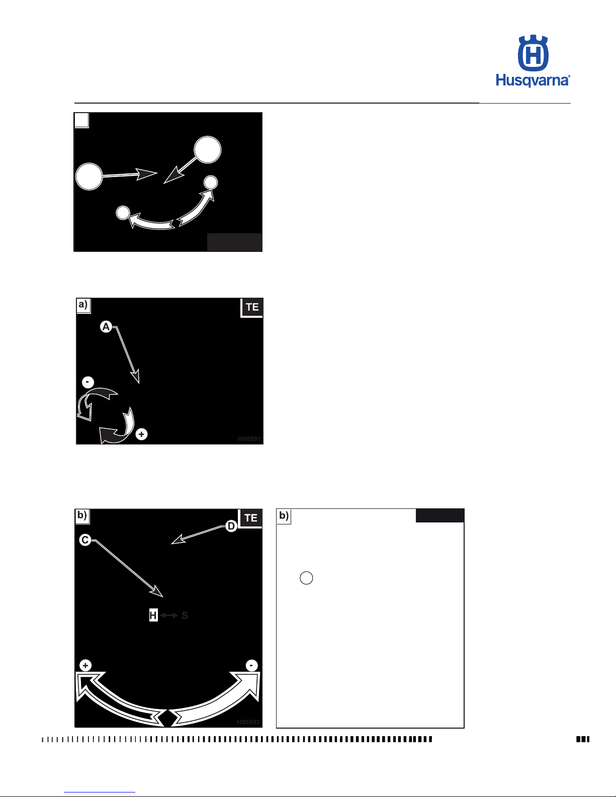
D.27
TE 250R - 310R 2013 I.E. / TE 310R 2013 I.E. USA
TC 250R 2013 - TC 250R 2013 I.E. USA
TXC 250R - 310R 2013 I.E. USA
H09087
A
-
TC - TXC
a)
D
+
H11259
C
TC-TXC
Workshop Manual Ed. 07-2012
SETTINGS AND ADJUSTMENTS
KAYABA front fork adjustment
- COMPRESSION (Fig. a)
(TC - TXC: TOP ADJUSTER; TE: LOWER ADJUSTER)
KAYABA: -9 clicks (TC EU - TXC);
KAYABA: -12 clicks (TE);
KAYABA: -10 clicks (TC 250 USA).
To reset the standard setting, turn cap nut (A) clockwise to reach the fully closed
position; then, turn it back by the mentioned clicks. In order to obtain a smooth
braking action, turn the adjuster counter clockwise. Vice versa to obtain a harder
braking action.
- REBOUND (Fig. b)
(TC - TXC: LOWER ADJUSTER; TE: TOP ADJUSTER)
KAYABA: -13 clicks (TC EU - TXC);
KAYABA: -8 clicks (TE);
KAYABA: -12 clicks (TC 250 USA).
To reset standard setting, turn adjuster (C) clockwise to reach the fully closed
position; then, turn it back by the mentioned clicks. In order to obtain a smooth
braking action, turn the adjuster counter clockwise. Vice versa to obtain a harder
braking action.
- BLEEDING (Fig. a/b) (to carry out after each competition, or monthly).
Set the motorcycle on a central stand, release the fork fully extended and loosen
the bleed valve (D). Once this operation is over, tighten the valve.
NOTE: Never force the adjuster screws beyond the maximum open and
closed positions.
Page 58
D.28
TE 250R - 310R 2013 I.E. / TE 310R 2013 I.E. USA
TC 250R 2013 - TC 250R 2013 I.E. USA
TXC 250R - 310R 2013 I.E. USA
H09090
3
1
2
H09091
2
1
H11282
SETTINGS AND ADJUSTMENTS
Workshop Manual Ed. 07-2012
Steering bearing clearance adjustment
For safety reasons, the steering should always be adjusted so that the handlebar
turns freely and without play. To check steering adjustment, set a stand or a block
under the engine and see that the front wheel is lifted from the ground. Press
lightly on the handlebar grips to cause the front end to rotate; the handlebar
should turn smoothly. Sit on the ground in front of the front wheel and hold the
lower ends of the fork legs. Push and pull in a front to rear motion to feel for play.
If any play is detected, adjust as follows:
- Loosen the steering head tube nut (1);
- Loosen the four bolts (3) that secure the fork legs to the steering head; Turn the steering head tube ring nut (2) clockwise using the special key until
achieving correct play adjustment;
- Tighten the steering head tube nut (1) to 8÷9 Kgm. (78.4÷88.3 Nm);
- Tighten the four bolts (3) on the steering head to 22.5-26.5 Nm (2.3-2.7 Kgm).
Steering angle adjustment
Steering angle can be modied by means of the adjuster assemblies located on
either side of the steering head tube as follows: loosen the check nut (1), turn
the adjuster screw (2) until setting the desired steering angle and then re-tighten
the check nut (1). Make the same changes on both sides.
Page 59
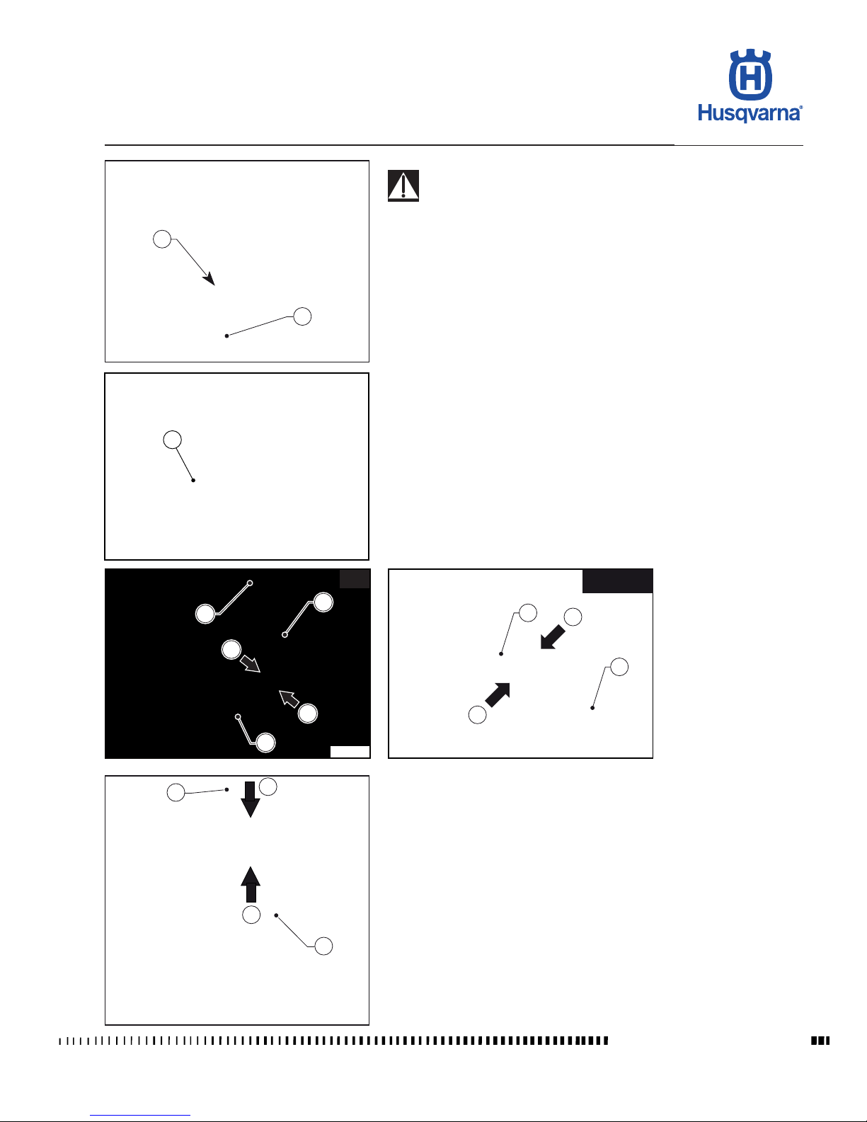
D.29
TE 250R - 310R 2013 I.E. / TE 310R 2013 I.E. USA
TC 250R 2013 - TC 250R 2013 I.E. USA
TXC 250R - 310R 2013 I.E. USA
H09093
TE-TXC
4
3
6
6
H09092
1
2
H11284
3
5
6
6
2
4
3
TC
6
6
H11103
H11283
2
Workshop Manual Ed. 07-2012
SETTINGS AND ADJUSTMENTS
Supply hose check
During the fuel tank removal operations, pay particular attention to
the couplings of the fuel hose on the pump body and on the throttle
body in order to prevent possible breakage / damages to the parts.
Remove saddle and side panels as described in Section "E".
Remove the tank (1) retaining screw (2).
Lift the tank (2) and check the hose (3) running from the pump (4) to the throttle
body (5).
To replace the hose, squeeze the two retainer tabs (6) at one end of the hose
and detach hose. Repeat at the other end of the hose.
Page 60
D.30
TE 250R - 310R 2013 I.E. / TE 310R 2013 I.E. USA
TC 250R 2013 - TC 250R 2013 I.E. USA
TXC 250R - 310R 2013 I.E. USA
H11148
H11147
2
TE-TXC
H11145
2
TC
H11285
1
1
TE-TXC
H11143
TC
1
H11287
2
TE-TXC
SETTINGS AND ADJUSTMENTS
Workshop Manual Ed. 07-2012
Exhaust system check
Perform a visual inspection of the exhaust system rst, in order to identify possible gas leaks from the sealing elements (gaskets), and to ensure that the
Silent-Blocks are not damaged.
Subsequently, inspect the single components by disassembling the exhaust
system.
In addition to this, check the tightening of the screws (1) of the anges and the
tightening of the screws (2) that strap the silencer to the respective supports.
The damaged or broken parts must be replaced.
Page 61

E.1
TE 250R - 310R 2013 I.E. / TE 310R 2013 I.E. USA
TC 250R 2013 - TC 250R 2013 I.E. USA
TXC 250R - 310R 2013 I.E. USA
E
GENERAL PROCEDURES
Workshop Manual Ed. 07-2012
Section
Page 62

E.2
TE 250R - 310R 2013 I.E. / TE 310R 2013 I.E. USA
TC 250R 2013 - TC 250R 2013 I.E. USA
TXC 250R - 310R 2013 I.E. USA
GENERAL PROCEDURES
Workshop Manual Ed. 07-2012
Sommario
Foreword ......................................................................................................E.3
Saddle removal.............................................................................................E.4
Side panel removal .......................................................................................E.4
Battery removal (TE-TCX) ............................................................................E.4
Rear chassis with mudguard and air box removal (TC) ...............................E.5
Rear chassis with mudguard and air box removal (TE-TXC) .......................E.5
Exhaust system removal ..............................................................................E.8
Fuel tank, scoops and spoiler removal .......................................................E.12
Fuel pump removal (TC).............................................................................E.16
Fuel pump removal (TE – TXC) ..................................................................E.17
Start-up relay removal (TE-TXC) ................................................................E.18
Condenser .................................................................................................E.18
Electronic control unit removal CDI ............................................................E.19
Voltage regulator removal (TE-TXC) ..........................................................E.19
Voltage regulator removal (TC) ..................................................................E.20
Coil / Stick-Coil removal ............................................................................E.20
Clutch hose removal ...................................................................................E.21
Horn removal (TE) ......................................................................................E.21
Electric cooling fan removal (TE-TXC) .......................................................E.22
Secondary drive chain removal ..................................................................E.22
Removal of engine from motorcycle ...........................................................E.23
Radiator removal ........................................................................................E.28
Thermostat removal (TE-XC) .....................................................................E.29
Page 63
E.3
TE 250R - 310R 2013 I.E. / TE 310R 2013 I.E. USA
TC 250R 2013 - TC 250R 2013 I.E. USA
TXC 250R - 310R 2013 I.E. USA
H11288
H11289
GENERAL PROCEDURES
Workshop Manual Ed. 07-2012
Foreword
This section describes the operations preliminary to engine removal.
Please note that, in order to gain access to certain motorcycle components (rear
shock absorber, electrical parts, wiring, etc.), it may be necessary to partially
remove some parts.
RIGHT-HAND SIDE LEFT-HAND SIDE
Page 64
E.4
TE 250R - 310R 2013 I.E. / TE 310R 2013 I.E. USA
TC 250R 2013 - TC 250R 2013 I.E. USA
TXC 250R - 310R 2013 I.E. USA
H10001
1
H10002
1
1
2
3
GENERAL PROCEDURES
Workshop Manual Ed. 07-2012
Saddle removal
- Turn the rear xing (1) counter clockwise and remove the saddle.
Side panel removal
- Remove the saddle as described in the relevant paragraph.
- Loosen the retaining screws (1) and remove the side panels (2) and (3).
Battery removal (TE-TCX)
- Remove the saddle as described in the relevant paragraph.
- First remove the BLACK negative cable (8 mm Allen wrench), then the RED
positive cable (when reassembling, rst connect the RED positive cable, then
the BLACK negative cable); remove the battery (1) from its housing.
Page 65
E.5
TE 250R - 310R 2013 I.E. / TE 310R 2013 I.E. USA
TC 250R 2013 - TC 250R 2013 I.E. USA
TXC 250R - 310R 2013 I.E. USA
H00633
2
1
H10003
1
H10004
2
3
H10005
6
4
5
GENERAL PROCEDURES
Workshop Manual Ed. 07-2012
Rear chassis with mudguard and air box removal (TC)
- Remove the saddle as described in the relevant paragraph.
- Remove the side panels as described in the relevant paragraph.
- Lift the tank at the rear end.
- Disconnect the air temperature sensor (1).
- Remove the exhaust silencer as described in the relevant para-
graph.
- Slacken clamp (2) that secures the rubber coupling of the air box (3) to the
throttle body.
- Remove the upper xing (4) and lower xings (5) on both sides of the rear
chassis using a 10 mm ring wrench.
- Pull the rear chassis (6) rearwards together with mudguard and air box, and
detach it from the main chassis.
Rear chassis with mudguard and air box removal (TE-TXC)
- Remove the following parts in the order given: saddle, side panels, fuel tank,
silencer and battery (see relevant paragraphs for instructions).
- Shear the plastic clips securing wiring to rear chassis.
- Disconnect the connector (1) of the turning indicator relay (2) (TE).
- Remove the solenoid starter (3) from its mount.
Page 66
E.6
TE 250R - 310R 2013 I.E. / TE 310R 2013 I.E. USA
TC 250R 2013 - TC 250R 2013 I.E. USA
TXC 250R - 310R 2013 I.E. USA
H00621
8
7
H11290
5
6
GENERAL PROCEDURES
Workshop Manual Ed. 07-2012
- Disconnect the connector (4) of the tail light unit (TE).
- Detach relays (5) and fuses (6) on the right-hand side of the motorcycle.
- Detach the breather hose (7) from the air lter (8).
Page 67
E.7
TE 250R - 310R 2013 I.E. / TE 310R 2013 I.E. USA
TC 250R 2013 - TC 250R 2013 I.E. USA
TXC 250R - 310R 2013 I.E. USA
H11291
9
8
10
GENERAL PROCEDURES
Workshop Manual Ed. 07-2012
- Unscrew the clamp (9) connecting air lter (8) to throttle body (10).
- Remove the four screws (11) of the rear chassis (12) using a 10 mm ring
wrench.
- Pull the rear chassis (12) rearwards together with mudguard and air box ,
and detach it from the main chassis.
Page 68
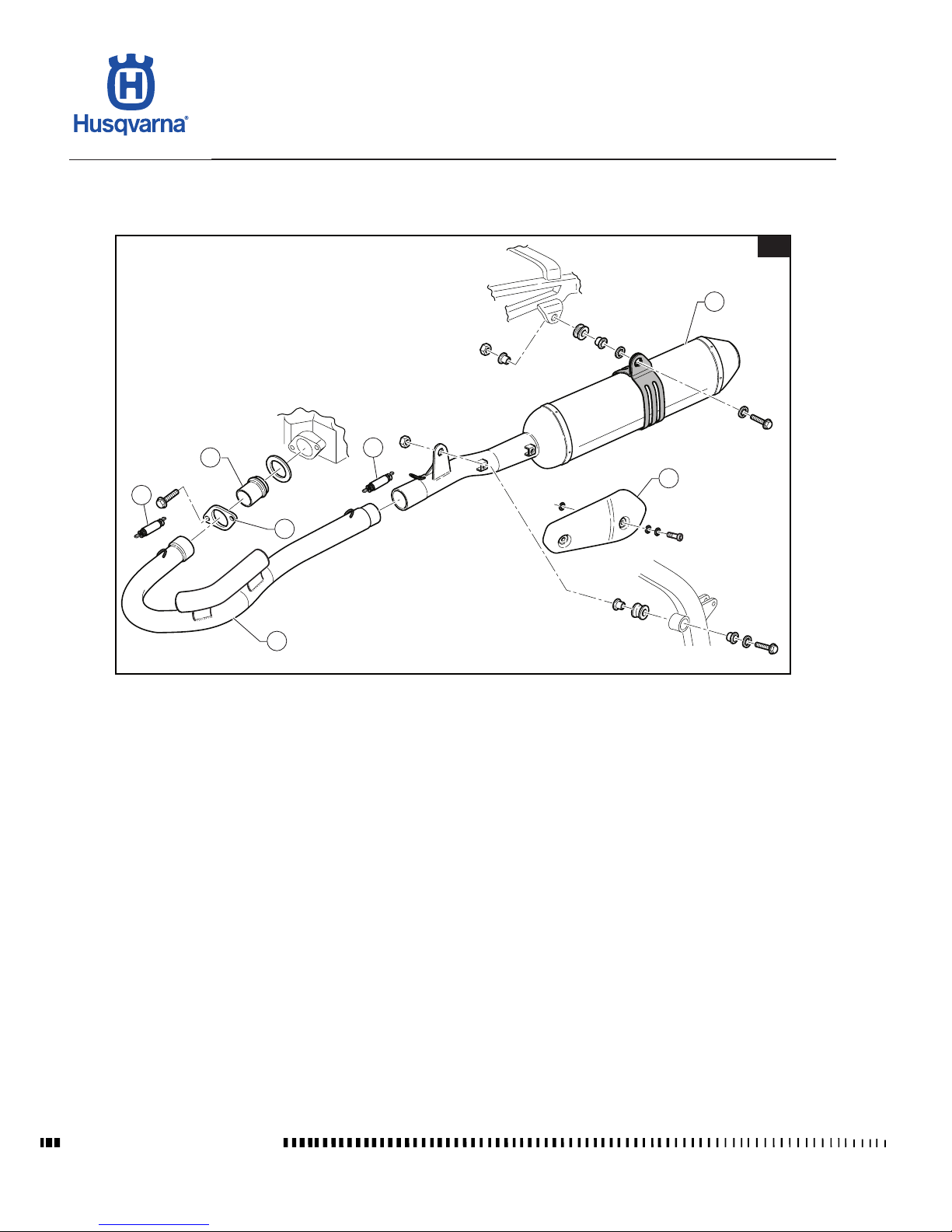
E.8
TE 250R - 310R 2013 I.E. / TE 310R 2013 I.E. USA
TC 250R 2013 - TC 250R 2013 I.E. USA
TXC 250R - 310R 2013 I.E. USA
H10966
TC
1
2
3
2
5
6
4
GENERAL PROCEDURES
Workshop Manual Ed. 07-2012
Exhaust system removal
Key:
1)
Silencer
2) Spring
3) Exhaust manifold
4) Flange
5) Nozzle
6) Protection
Page 69
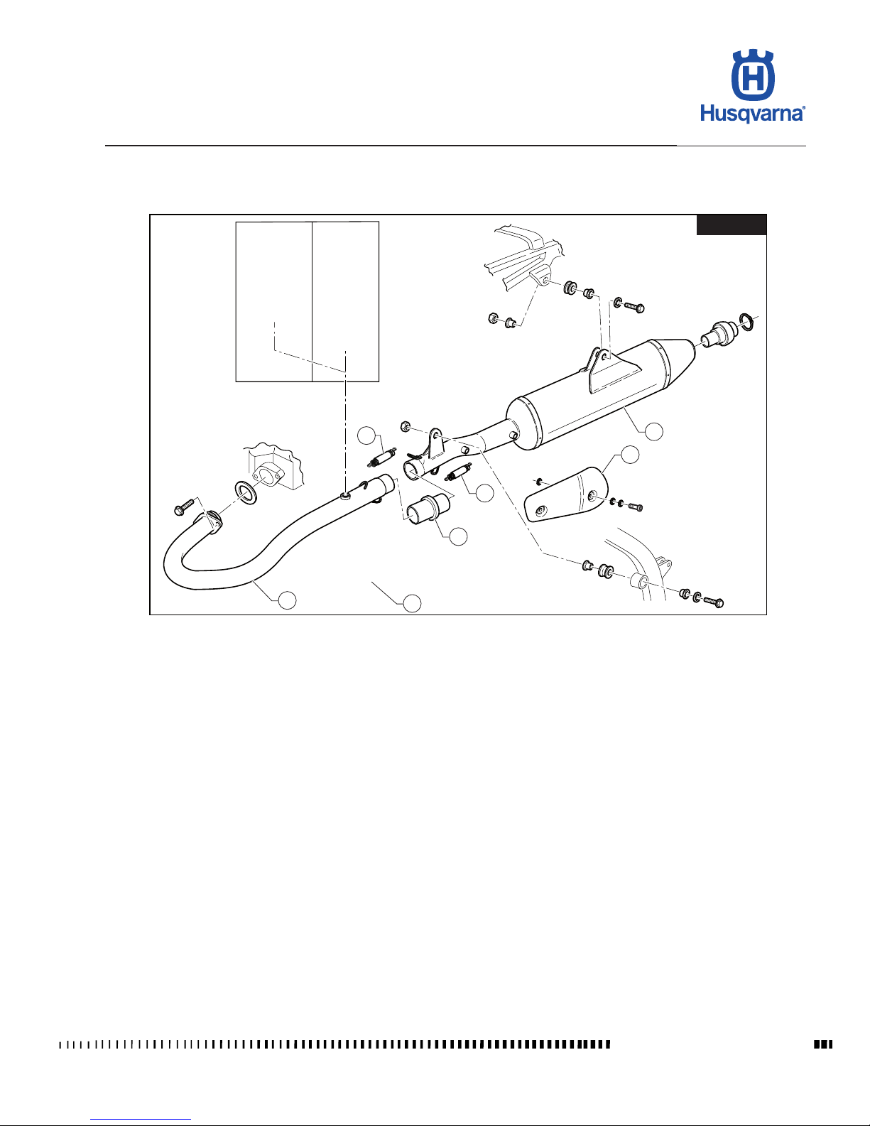
E.9
TE 250R - 310R 2013 I.E. / TE 310R 2013 I.E. USA
TC 250R 2013 - TC 250R 2013 I.E. USA
TXC 250R - 310R 2013 I.E. USA
H11292
TE-TXC
1
2
3
4
5
2
6
GENERAL PROCEDURES
Workshop Manual Ed. 07-2012
Key:
1) Silencer
2) Spring
3) Exhaust manifold
4) Front protection
5) Rear protection
6) Catalyst
Page 70
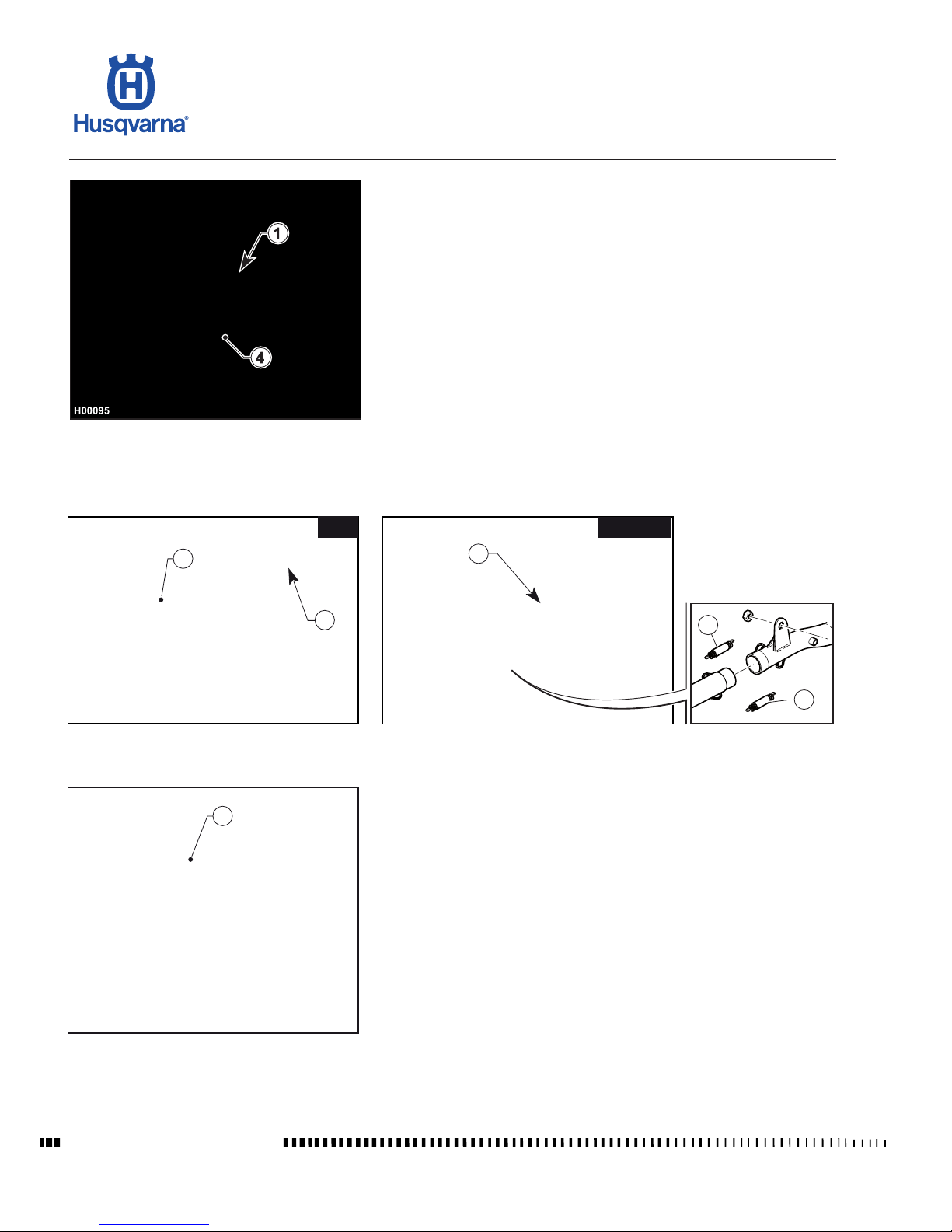
E.10
TE 250R - 310R 2013 I.E. / TE 310R 2013 I.E. USA
TC 250R 2013 - TC 250R 2013 I.E. USA
TXC 250R - 310R 2013 I.E. USA
H10010
3
TE-TXC
H11464
2
2
H10008
3
2
TC
H11293
7
GENERAL PROCEDURES
Workshop Manual Ed. 07-2012
- Remove the saddle as described in the relevant paragraph.
- Remove the left-hand side panel as described in the relevant paragraph.
- Using an 8 mm T-wrench on the outside and a 10 mm T-wrench on the inside,
remove the silencer (4) retaining screw (1).
- Remove the spring (2) and the screw (3) using an 8 mm T-wrench; slide out
the silencer (4).
- Disconnect the Lambda sensor connector (7) and shear the wiring clips (TETXC).
Page 71
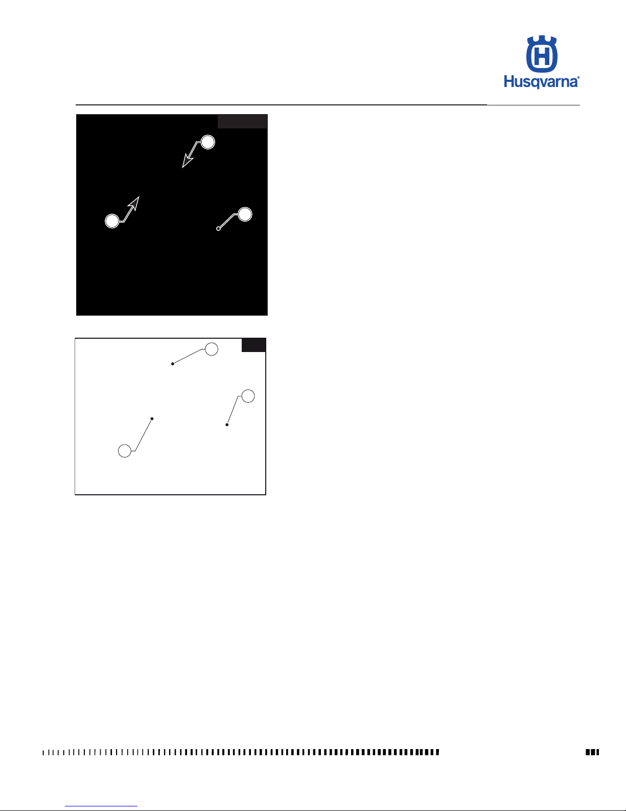
E.11
TE 250R - 310R 2013 I.E. / TE 310R 2013 I.E. USA
TC 250R 2013 - TC 250R 2013 I.E. USA
TXC 250R - 310R 2013 I.E. USA
H10011
5
6
5
TE-TXC
H10012
7
6
TC
7
GENERAL PROCEDURES
Workshop Manual Ed. 07-2012
(TE-TXC)
- Loosen the two bolts (5) and remove the exhaust pipe (6).
(TC)
- Detach springs (7) and remove exhaust pipe (6).
Page 72
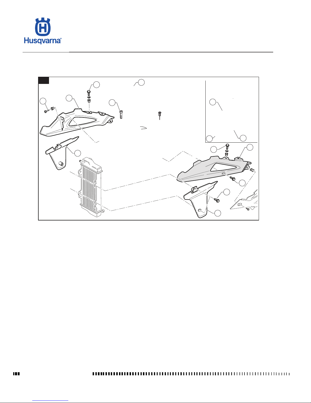
E.12
TE 250R - 310R 2013 I.E. / TE 310R 2013 I.E. USA
TC 250R 2013 - TC 250R 2013 I.E. USA
TXC 250R - 310R 2013 I.E. USA
H10013
TC
1
2
3
4
3
5
6
3
4
3
6
10
11
12
GENERAL PROCEDURES
Workshop Manual Ed. 07-2012
Fuel tank, scoops and spoiler removal
Page 73
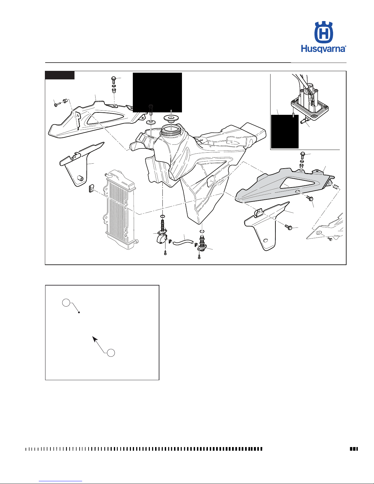
E.13
TE 250R - 310R 2013 I.E. / TE 310R 2013 I.E. USA
TC 250R 2013 - TC 250R 2013 I.E. USA
TXC 250R - 310R 2013 I.E. USA
H00630
3
2
1
3
4
6
7
8
9
3
4
10
11
5
6
3
H10014
TE-TXC
H10015
2
1
GENERAL PROCEDURES
Workshop Manual Ed. 07-2012
- Remove the saddle as described in the relevant paragraph.
- Remove the side panels as described in the relevant paragraph.
- Remove the breather hose (1).
- Loosen the fuel tank retaining screw (2).
Page 74
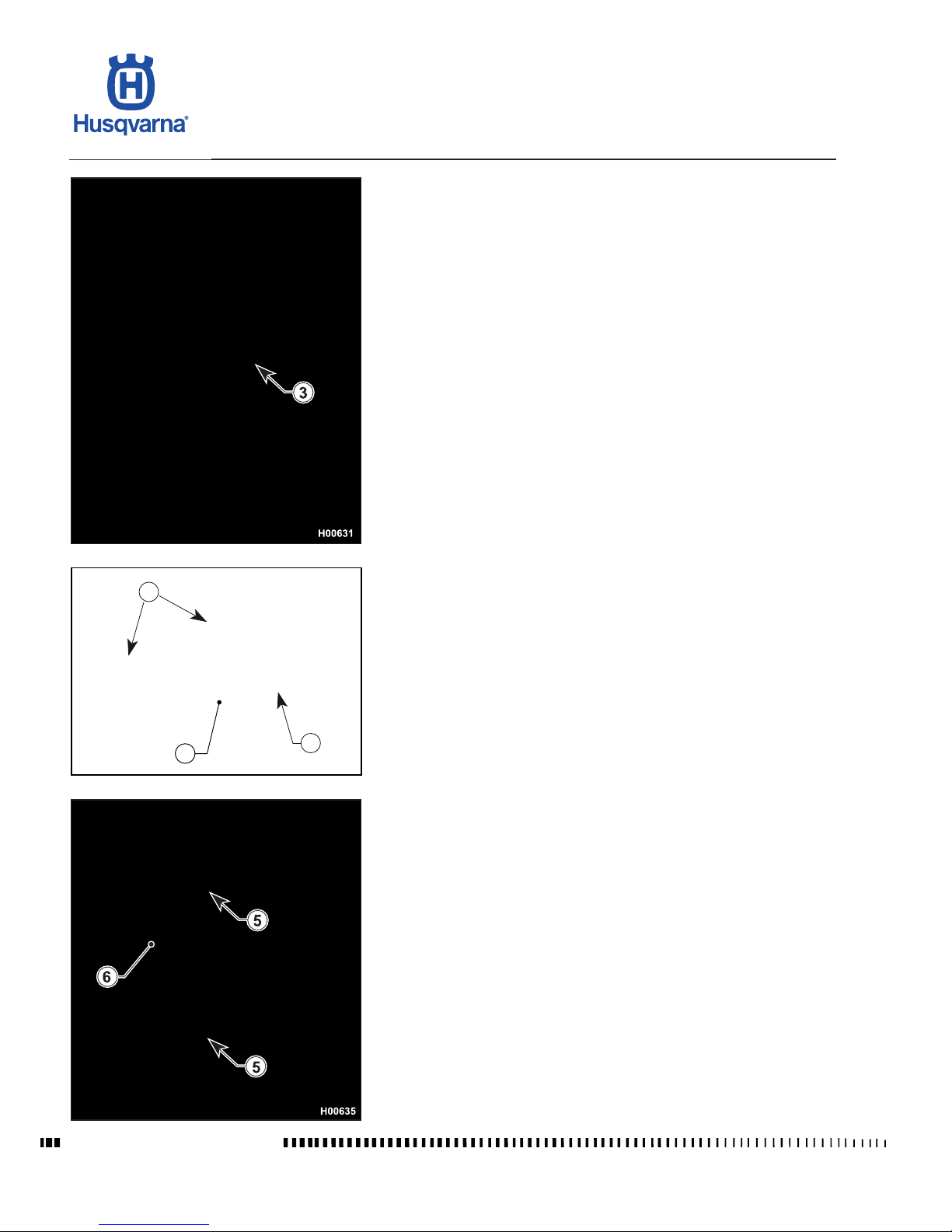
E.14
TE 250R - 310R 2013 I.E. / TE 310R 2013 I.E. USA
TC 250R 2013 - TC 250R 2013 I.E. USA
TXC 250R - 310R 2013 I.E. USA
H02212
4
3
3
GENERAL PROCEDURES
Workshop Manual Ed. 07-2012
- Remove the screws (3) retaining the scoops to the fuel tank. Remove the
scoops (4) and the screws (5) retaining the spoilers (6) to the radiators and
then remove the spoilers.
Page 75
E.15
TE 250R - 310R 2013 I.E. / TE 310R 2013 I.E. USA
TC 250R 2013 - TC 250R 2013 I.E. USA
TXC 250R - 310R 2013 I.E. USA
H10020
12
10
11
TE-TXC
H10018
7
6
TE-TXC
H10019
8
9
TE-TXC
H02216
13
H10016
8
TC
H10017
7
TC
GENERAL PROCEDURES
Workshop Manual Ed. 07-2012
Carefully disconnect the fuel hoses from the throttle body or from
the fuel pump to prevent damage to the quick coupling.
(TC)
- Disconnect the fuel hose (7) from the throttle body.
- Lift the tank and disconnect the fuel pump connector (8) from the main wiring
harness.
(TE-TXC)
- Close the two taps (7) and (8) and connect the hose (9).
- Disconnect connector (6) of the reserve sensor.
- Lift the tank and disconnect the hose (10) from the fuel pump outlet tting
(11) in the bottom section of the tank.
- Disconnect the fuel pump connector (12) from the main wiring harness.
- Slide out the tank (13).
Page 76
E.16
TE 250R - 310R 2013 I.E. / TE 310R 2013 I.E. USA
TC 250R 2013 - TC 250R 2013 I.E. USA
TXC 250R - 310R 2013 I.E. USA
H00648
2
H02339
GENERAL PROCEDURES
Workshop Manual Ed. 07-2012
Fuel pump removal (TC)
- Remove the fuel tank as described in the relevant paragraph.
- Remove the tank ller cap and pour the fuel contained in the tank into a ves-
sel of adequate capacity.
- Use an Allen wrench to loosen the 6 screws (1) and remove the pump (2).
On assembly, make sure that the pump O-ring (3) is correctly po-
sitioned in its seat.
Page 77
E.17
TE 250R - 310R 2013 I.E. / TE 310R 2013 I.E. USA
TC 250R 2013 - TC 250R 2013 I.E. USA
TXC 250R - 310R 2013 I.E. USA
H02340
1
3
2
4
3
H02341
4
5
7
6
H02342
2
GENERAL PROCEDURES
Workshop Manual Ed. 07-2012
Fuel pump removal (TE – TXC)
- Remove the fuel tank as described in the relevant paragraph.
- Remove the tank ller cap and pour the fuel contained in the tank into a vessel of adequate capacity.
- Make use of a 10 mm wrench to slacken the 4 screws (1) of the pump ange
(2) and the four screws (3) of the tting ange (4).
- Slide the tting ange (4) out of the tank, then remove the delivery and return
hoses by releasing the quick ttings (5) and (6).
- Disconnect the pump supply connector (7).
- Slide the pump (2) with relevant small hoses out of the tank.
NOTE: To ret the pump follow the removal reverse procedure and make
sure that the seals under the anges (2) and (4) are not worn.
Page 78
E.18
TE 250R - 310R 2013 I.E. / TE 310R 2013 I.E. USA
TC 250R 2013 - TC 250R 2013 I.E. USA
TXC 250R - 310R 2013 I.E. USA
H10021
1
2
H11106
4
3
GENERAL PROCEDURES
Workshop Manual Ed. 07-2012
Start-up relay removal (TE-TXC)
- Remove saddle and left-hand side panel (in this order) as outlined in the
relevant paragraphs.
- Disconnect the negative and positive cables of the battery.
- Disconnect the starter motor positive cable (1) from the solenoid starter.
- Disconnect the connector (2) and remove the solenoid starter (3) from its
mount.
Condenser
This operation must be performed with a cool engine.
- Cut the clamp (1) and disconnect the connector (2).
- Pull outwards the condenser (3) so that it comes out of the supporting bracket
(4).
Page 79
E.19
TE 250R - 310R 2013 I.E. / TE 310R 2013 I.E. USA
TC 250R 2013 - TC 250R 2013 I.E. USA
TXC 250R - 310R 2013 I.E. USA
H11294
1
3
H11295
2
H11296
1
2
H11297
4
3
GENERAL PROCEDURES
Workshop Manual Ed. 07-2012
Electronic control unit removal CDI
Remove: saddle and fuel tank as described in the relevant paragraphs.
Unhook the support elastic (1) then detach the connector (2) and remove the
control unit (3).
Voltage regulator removal (TE-TXC)
- Disconnect the connectors (1) and (2).
- Loosen the two retaining screws (3) and remove the regulator (4).
Page 80
E.20
TE 250R - 310R 2013 I.E. / TE 310R 2013 I.E. USA
TC 250R 2013 - TC 250R 2013 I.E. USA
TXC 250R - 310R 2013 I.E. USA
H11112
3
1
2
4
H11113
5
1
H11109
1
H11110
2
3
GENERAL PROCEDURES
Workshop Manual Ed. 07-2012
Voltage regulator removal (TC)
- Remove the fuel tank as described in the relevant paragraph.
- Disconnect the connector (1).
- Loosen the two screws (2) and remove the voltage regulator (3).
Coil / Stick-Coil removal
- With an 8-mm wrench loosen the screws (2), then remove the oater needle
(1).
- Disconnect the connector (3) and remove the coil / Stick-Coil (4).
- During the reassembly, pay attention to the positioning of the gasket (5) with
respect to the plate (1).
Page 81
E.21
TE 250R - 310R 2013 I.E. / TE 310R 2013 I.E. USA
TC 250R 2013 - TC 250R 2013 I.E. USA
TXC 250R - 310R 2013 I.E. USA
GENERAL PROCEDURES
Workshop Manual Ed. 07-2012
Clutch hose removal
- Loosen the tting (1) of the clutch hose (2) on the left-hand of the engine.
- Drain any oil left in the hose. On assembly, bleed the clutch system as de-
scribed in Section "P".
Horn removal (TE)
- Remove saddle and fuel tank (in this order) as outlined in the relevant para-
graphs.
- Loosen the screw (1) securing the spoiler to the right-hand radiator.
- Disconnect the two connectors (2) and remove the horn (3) with its bracket.
Page 82
E.22
TE 250R - 310R 2013 I.E. / TE 310R 2013 I.E. USA
TC 250R 2013 - TC 250R 2013 I.E. USA
TXC 250R - 310R 2013 I.E. USA
H11299
5
H02226
1
1
2
H11298
1
H11300
3
4
GENERAL PROCEDURES
Workshop Manual Ed. 07-2012
Electric cooling fan removal (TE-TXC)
- Remove saddle, fuel tank and scoops (in this order) as outlined in the relevant
paragraphs.
- Disconnect the connector (1).
- Loosen the screw (2) and remove the electric fan (3).
Secondary drive chain removal
The following procedure applies to both O-ring chains and chains without O-rings:
- Remove: screws (1), sprocket guard (2), clip (3), master link (4) and chain
(5).
Page 83
E.23
TE 250R - 310R 2013 I.E. / TE 310R 2013 I.E. USA
TC 250R 2013 - TC 250R 2013 I.E. USA
TXC 250R - 310R 2013 I.E. USA
H11301
2
3
1
H11302
1
H11303
4
H11304
5
TE - TXC
H11305
TC
5
GENERAL PROCEDURES
Workshop Manual Ed. 07-2012
Removal of engine from motorcycle
- Remove the saddle as described in the relevant paragraph.
- Remove the side panels as described in the relevant paragraph.
- Remove the fuel tank as described in the relevant paragraph.
- Remove the exhaust system as described in the relevant paragraph.
- Remove the engine guard as outlined in the respective section.
- Loosen the two screws (1) of the intake manifold (2) by removing the throttle
body (3) from the head.
- Remove the connector (4) of the coil / Stick-Coil.
- Disconnect the connector (5) of the generator.
Page 84
E.24
TE 250R - 310R 2013 I.E. / TE 310R 2013 I.E. USA
TC 250R 2013 - TC 250R 2013 I.E. USA
TXC 250R - 310R 2013 I.E. USA
H10040
8
H02345
20
21
H11306
11
13
12
14
H11307
18
19
17
GENERAL PROCEDURES
Workshop Manual Ed. 07-2012
- Place a vessel on the left-hand side of the cylinder, under the engine.
- Slacken the radiator cap (8).
- Slacken the clamp (11) and disconnect the hose (12) connecting the radiators
to the engine. Drain all uid.
- Slacken the clamp (13) and disconnect the hose (14) connecting the radiator
to the water pump.
TE 310
- Due to the blow-by circuit structure, engine oil must be drained in the TE
310 version.
For the oil draining operation, follow the instructions outlined in the respec-
tive section.
- Disconnect the connector (17) from the coil / Stick-Coil.
- Open the clamp (18) and detach the small blow-by tube (19) from the cylinder
head cover.
- Remove the chain as described in the relevant paragraph.
- Remove the chain guide plate (20) unscrewing the screw (21) with an 8 mm
wrench.
Page 85
E.25
TE 250R - 310R 2013 I.E. / TE 310R 2013 I.E. USA
TC 250R 2013 - TC 250R 2013 I.E. USA
TXC 250R - 310R 2013 I.E. USA
H02231
22
23
H11308
24
H11309
25
26
TE - TXC
H11310
TC
25
GENERAL PROCEDURES
Workshop Manual Ed. 07-2012
- Loosen the three screws (22) and remove the clutch actuator (23).
- Remove the clip (24) that holds clutch hose and wiring harness together.
- Remove the water temperature sensor connector (25).
- Remove the ground cables (26) (TE-TXC).
Page 86
E.26
TE 250R - 310R 2013 I.E. / TE 310R 2013 I.E. USA
TC 250R 2013 - TC 250R 2013 I.E. USA
TXC 250R - 310R 2013 I.E. USA
H11313
31
32
H11311
27
TE-TXC
H11312
28
30
29
GENERAL PROCEDURES
Workshop Manual Ed. 07-2012
- Remove the positive power supply cable (27) of the starter motor (TE-TXC).
- To remove the brake lever (28), use an 8 mm wrench to loosen the master
cylinder linkage (29) and a 6 mm Allen wrench to loosen the central screw
(34). Remove the lever.
- Loosen the upper retaining screw (31) of the shock absorber (32) with a 14
mm wrench.
Page 87
E.27
TE 250R - 310R 2013 I.E. / TE 310R 2013 I.E. USA
TC 250R 2013 - TC 250R 2013 I.E. USA
TXC 250R - 310R 2013 I.E. USA
H11314
33
34
H11315
35
35
H11316
36
H11317
37
GENERAL PROCEDURES
Workshop Manual Ed. 07-2012
- Remove the guards (33) on both sides shearing the clips (34).
- Remove the engine mounting bolts (35) using a 12 mm wrench on the lefthand side and a 10 mm wrench on the right-hand side.
- Loosen the swinging arm axle nut (36) using a 22 mm wrench; pull out the
axle (37) from the right-hand side of the engine and pull the swinging arm
rearwards to facilitate engine removal.
- Lift the engine, tilt it to the left and remove it from the motorcycle.
- Place the engine on a rotating stand to perform the procedures described in
Sections F-G-H.
Page 88
E.28
TE 250R - 310R 2013 I.E. / TE 310R 2013 I.E. USA
TC 250R 2013 - TC 250R 2013 I.E. USA
TXC 250R - 310R 2013 I.E. USA
H00685
13
7
6
8
H00687
9
10
11
12
H11318
1
2
3
4
5
GENERAL PROCEDURES
Workshop Manual Ed. 07-2012
Radiator removal
- Remove the fuel tank together with scoops and spoilers as outlined in the
relevant paragraphs.
- Remove the electric cooling fan (TE – TXC) as described in the relevant
paragraph.
- Place a pan under the hose (1) to collect coolant, then loosen the clamp (2),
detach the hose (1) and drain all coolant.
- Loosen the clamp (3) and disconnect the hose (4) from the left-hand radiator
(5).
- Loosen the clamp (6) and disconnect the hose (7) from the right-hand radiator
(8).
- Remove the plastic grids (9) from the radiators.
- Remove the clamp (10) and disconnect the radiator connecting hose (11).
Page 89
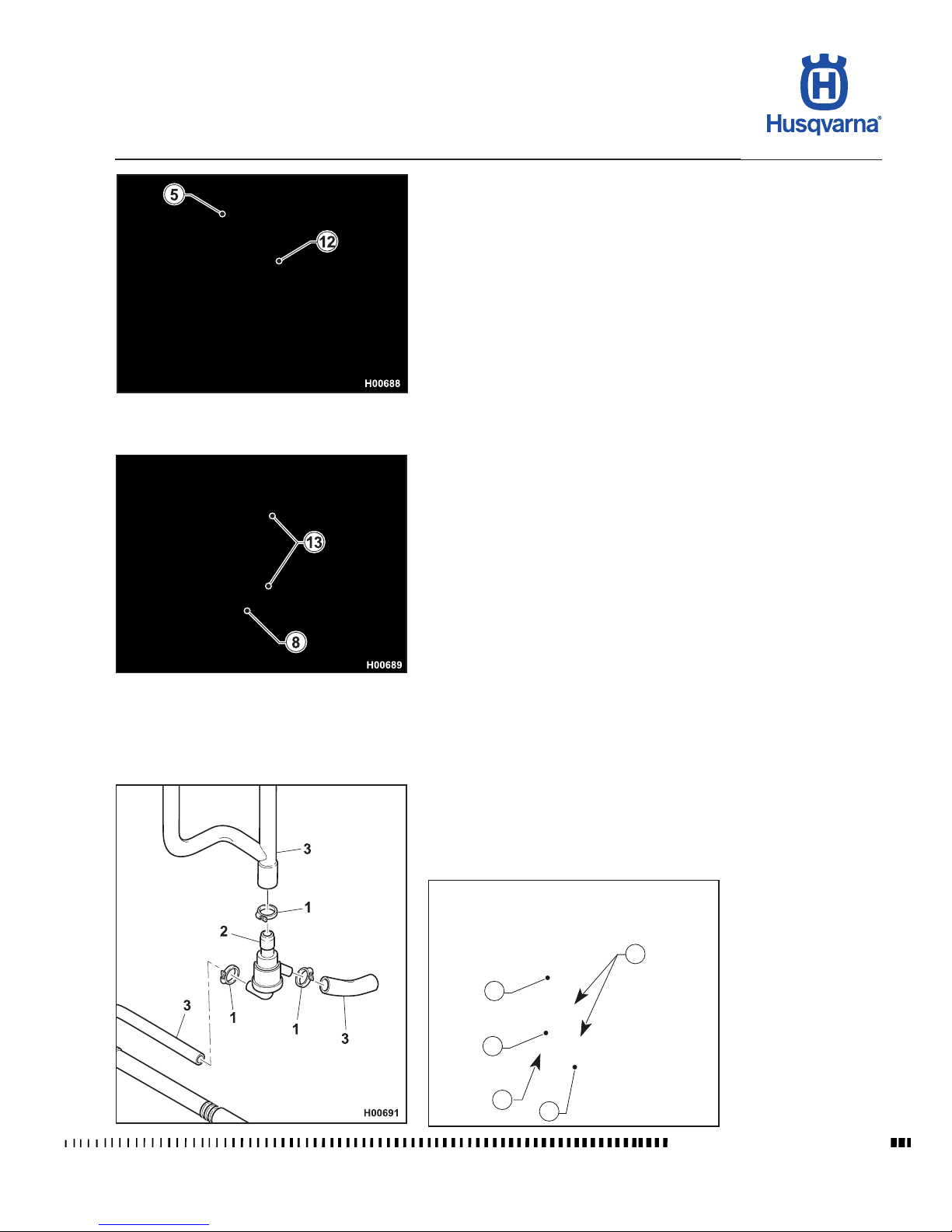
E.29
TE 250R - 310R 2013 I.E. / TE 310R 2013 I.E. USA
TC 250R 2013 - TC 250R 2013 I.E. USA
TXC 250R - 310R 2013 I.E. USA
H11319
1
1
2
3
3
GENERAL PROCEDURES
Workshop Manual Ed. 07-2012
- Loosen the screws (12) and remove the left-hand radiator (5).
- Loosen the screws (13) and remove the right-hand radiator (8).
Thermostat removal (TE-XC)
- Remove the fuel tank and the left-hand spoiler as outlined in the relevant
paragraph.
- Loosen the three clamps (1) securing the thermostat (2).
- Disconnect the hoses (3) and remove the thermostat (2).
Page 90

Page 91

F.1
TE 250R - 310R 2013 I.E. / TE 310R 2013 I.E. USA
TC 250R 2013 - TC 250R 2013 I.E. USA
TXC 250R - 310R 2013 I.E. USA
F
ENGINE DISASSEMBLY
Workshop Manual Ed. 07-2012
Section
Page 92

F.2
TE 250R - 310R 2013 I.E. / TE 310R 2013 I.E. USA
TC 250R 2013 - TC 250R 2013 I.E. USA
TXC 250R - 310R 2013 I.E. USA
ENGINE DISASSEMBLY
Workshop Manual Ed. 07-2012
Sommario
Layout of engine components (TE - TXC) .................................................... F.3
Layout of engine components ...................................................................... F. 4
Cylinder head cover removal ........................................................................ F.5
Camshaft removal ....................................................................................... F. 6
Water pump body removal ........................................................................... F. 8
Water pump disassembly ............................................................................. F.9
Cylinder head removal................................................................................ F.10
Valve removal ............................................................................................ F.14
Cylinder removal......................................................................................... F.16
Piston removal ............................................................................................ F.16
Flywheel removal........................................................................................ F.17
Kick start pedal removal ............................................................................. F.18
Sprocket removal........................................................................................ F.18
Oil lter removal.......................................................................................... F.19
Clutch cover removal .................................................................................. F.20
Clutch disassembly..................................................................................... F.21
Slider removal............................................................................................. F.24
Kick start disassembly ................................................................................ F.24
Starter motor removal (TE-TXC) ................................................................ F.26
Starter motor disassembly (TE-TXC) ......................................................... F.28
Starter drive disassembly (TE-TXC) ........................................................... F.28
Oil pump disassembly ................................................................................ F.31
Gear shift pedal and selector assembly removal........................................ F.32
Primary drive gear removal ........................................................................ F.34
Crankcase disassembly.............................................................................. F.35
Gearbox disassembly ................................................................................. F.36
Crankshaft disassembly ............................................................................. F.38
Page 93
F.3
TE 250R - 310R 2013 I.E. / TE 310R 2013 I.E. USA
TC 250R 2013 - TC 250R 2013 I.E. USA
TXC 250R - 310R 2013 I.E. USA
H11320
4
2
3
5
6
7
8
9
10
H11321
5
11
1
12
2
ENGINE DISASSEMBLY
Workshop Manual Ed. 07-2012
Layout of engine components (TE - TXC)
1 Sprocket
2 Cylinder head cover
3 Cylinder head
4 Chain tensioner
5 Cylinder
6 Starter motor
7 Head lubrication pipe
8 Oil lter
9 Clutch cover
10 Kick start lever
11 Water pump
12 Alternator cover
Page 94
F.4
TE 250R - 310R 2013 I.E. / TE 310R 2013 I.E. USA
TC 250R 2013 - TC 250R 2013 I.E. USA
TXC 250R - 310R 2013 I.E. USA
H10973
1
2
4
12
9
10
H11114
1
11
3
7
6
4
5
2
8
ENGINE DISASSEMBLY
Workshop Manual Ed. 07-2012
Layout of engine components
1 Cylinder head cover
2 Cylinder head
3 Chain tensioner
4 Cylinder
5 Head lubrication pipe
6 Oil lter
7 Clutch cover
8 Kick start lever
9 Water pump
10 Alternator cover
11 Coolant temperature thermostat
Page 95
F.5
TE 250R - 310R 2013 I.E. / TE 310R 2013 I.E. USA
TC 250R 2013 - TC 250R 2013 I.E. USA
TXC 250R - 310R 2013 I.E. USA
H11322
1
1
2
ENGINE DISASSEMBLY
Workshop Manual Ed. 07-2012
Cylinder head cover removal
- Remove the four retaining screws (1) and remove the head cover (2) with its
gasket.
Page 96
F.6
TE 250R - 310R 2013 I.E. / TE 310R 2013 I.E. USA
TC 250R 2013 - TC 250R 2013 I.E. USA
TXC 250R - 310R 2013 I.E. USA
H10980
1
1
1
2
H10981
1
1
2
H11149
3
3
H10989
H10990
3
3
ENGINE DISASSEMBLY
Workshop Manual Ed. 07-2012
Camshaft removal
- Remove the six retaining screws (1) of the alternator cover (2) (4 mm Allen
wrench) and remove the cover with its gasket.
- With a 17mm wrench, position the piston on the TDC at the end of the compression phase. In this condition, the two engraved reference marks (3) on
the gears of the camshafts are positioned on the same axle although they
are diametrically opposed.
INTAKE OUTLET
Page 97
F.7
TE 250R - 310R 2013 I.E. / TE 310R 2013 I.E. USA
TC 250R 2013 - TC 250R 2013 I.E. USA
TXC 250R - 310R 2013 I.E. USA
H10982
4
5
6
H10983
7
H10984
8
H10985
9
9
10
ENGINE DISASSEMBLY
Workshop Manual Ed. 07-2012
- Remove the spark plug (4) (16 mm wrench) and the head lubrication pipe (5)
loosening the drilled screw (6) (12 mm wrench).
- Remove the bushing (7) from the spark plug recess.
When you ret the bushing (7) make sure not to damage the O-Ring
(8).
- Loosen the screws (9) with a 5-mm wrench, and remove the mount (10).
Page 98
F.8
TE 250R - 310R 2013 I.E. / TE 310R 2013 I.E. USA
TC 250R 2013 - TC 250R 2013 I.E. USA
TXC 250R - 310R 2013 I.E. USA
H10987
11
12
H11323
1
1
2
ENGINE DISASSEMBLY
Workshop Manual Ed. 07-2012
- Remove the intake camshaft (11) and the exhaust camshaft (12).
Water pump body removal
- Remove the four screws (1) securing pump body (2) to head (4 mm Allen
wrench) and remove pump body.
Page 99
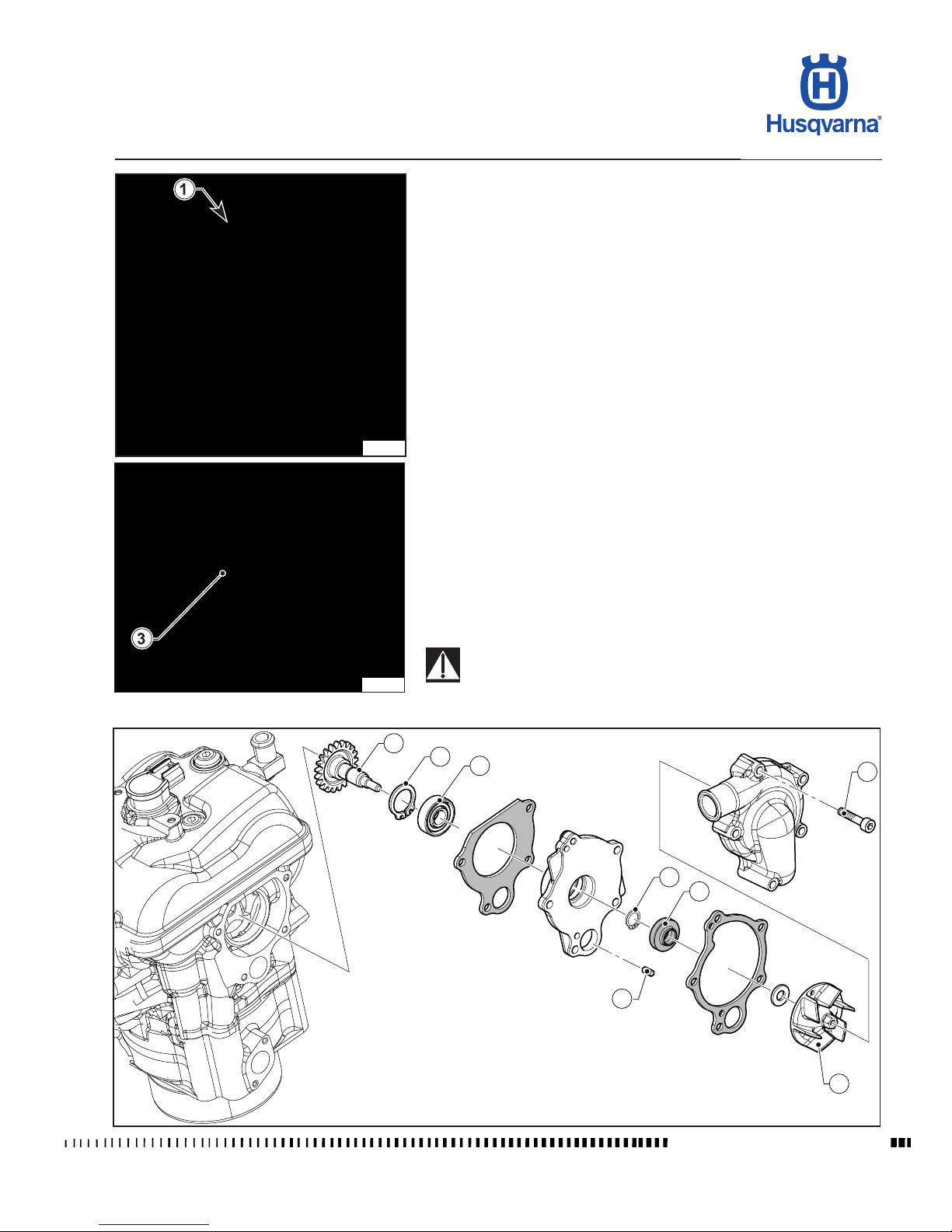
F.9
TE 250R - 310R 2013 I.E. / TE 310R 2013 I.E. USA
TC 250R 2013 - TC 250R 2013 I.E. USA
TXC 250R - 310R 2013 I.E. USA
H11325
H11326
1
8
3
4
5
6
9
7
H11324
ENGINE DISASSEMBLY
Workshop Manual Ed. 07-2012
Water pump disassembly
- Loosen the screw (1) to disassemble the pump.
- Loosen the impeller (3) and remove it.
- Remove the oil seal (4), remove the seeger (7) and remove the gear (5).
Remove the seeger (9) and remove the bearing (6).
During the ret, make sure that the centring plugs (8) are correctly
positioned in their own seat. Make also sure the pump gear (5) and
the camshaft gear are correctly timed.
Page 100
F.10
TE 250R - 310R 2013 I.E. / TE 310R 2013 I.E. USA
TC 250R 2013 - TC 250R 2013 I.E. USA
TXC 250R - 310R 2013 I.E. USA
H11327
1
2
H11328
3
H11329
4
4
1
ENGINE DISASSEMBLY
Workshop Manual Ed. 07-2012
Cylinder head removal
- Remove the head cover as described in the relevant paragraph.
- Remove the camshafts as described in the relevant paragraph.
- Remove the chain tensioner (1) as follows:
• Loosen the screw (2) with an 8 mm wrench.
• Turn the screw (3) fully clockwise with a at head screwdriver until locking
it so as to release the spring.
• Loosen the two screws (4) using an 8 mm wrench and remove the chain
tensioner (1).
 Loading...