

Page 1
Page 2

BEFORE YOU BEGIN: Read and understand all warnings and instructions before operating the Machine
described in this manual. WARNINGS AND CAUTIONS IN THIS MANUAL MUST BE UNDERSTOOD
AND FOLLOWED! FAILURE TO OBEY WARNINGS MAY RESULT IN SERIOUS INJURY OR DEATH.
IT IS YOUR RESPONSIBILITY to make sure persons who use this machine have read this manual.
If you have any questions about this machine and/or the operating instructions, DO NOT use the machine
until you have contacted Target and we have advised you!
CONTENTS .................................................................................................................................. PAGE NO.
Symbol Definitions ......................................................................................................................... 3 - 6
Decal Descriptions And Locations ................................................................................................. 7
WARNINGS.................................................................................................................................... 8 - 9
Saw Dimensions .......................................................................................................................... 10
Specifications & Power Source .....................................................................................................11
Parts Identification & Diagram....................................................................................................... 12
INSTRUCTIONS
1 Features...................................................................................................................................... 13
2 Assembly .................... .............................................................................................................. 13
3 Check Before Operating............................................................................................................. 14
4 Fitting the Blade ....... ................................................................................................................. 15
5 Operating Instructions .................................................................................................................15 - 18
6 Incidents During Operation ........................................................................................................ 18
7 Maintenance .............................................................................................................................. 18 - 20
8 V-Belt Tension ............... ............................................................................................................ 20 - 21
9 Important Advice ........................................................................................................................ 21
10 Accessories .............................................................................................................................. 21
11 Repairs ..................................................................................................................................... 21
12 Spare Parts .............................................................................................................................. 21
Reference Information & Notes ..................................................................................................... 22 - 23
Company & Contact Information ................................................................................................... Back Cover
Reference Information:
Model No.: ________________________________
Serial No.: ________________________________
Date Purchased: __________________________
NOTES / NOTAS:
_____________________________________________________________________________________
_____________________________________________________________________________________
_____________________________________________________________________________________
_____________________________________________________________________________________
_____________________________________________________________________________________
2
Page 3
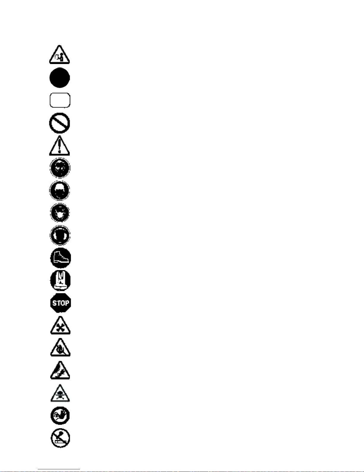
Symbol Definitions
Definicion De Los Simbolos
• Please read the instructions for use prior to operating the machine for the first time.
• Antes de la puesta en marcha, lea detenidamente las instrucciones y familiaricese con la
máquina.
• Mandatory
• Obligatorio
• Indication
• Indicación
• Prohibition
• Prohibición
• Warning Triangle
• Triángwulo De Advertencia
• Wear Eye Protection
• Usar Gafas De Protección
• Wear a Hard Hat
• Usar Casco Duro
• Wear Breathing Protection
• Usar Máscara De Protección
• The Use Of Ear Protection Is Mandatory
• Es Obligatorio El Uso De Protección Auditiva
• Wear Safety Shoes
• Usar Zapatos De Seguridad
• Wear Appropriate Clothing
• Usar Ropa Adecuada
• Motor Off
• Parar El Motor
• Use In Well Ventilated Area
• Usar En Una Área Bien Ventilada
• Do Not Use In Flammable Areas
• No Usar In Áreas Inflamables
• Machinery Hazard, Keep Hands And Feet Clear.
• Máquina Peligrosa - Mantenga Manos Y Pies Alejados De La Máquina
• Danger, Poison Exhaust Gas
• Peligro, Gases De Escape Tóxicos
• No Non-working Personnel In Area
• Prohibido Para Personas Ajenas A La Obra
• No Smoking
• No Fumar
3
Page 4
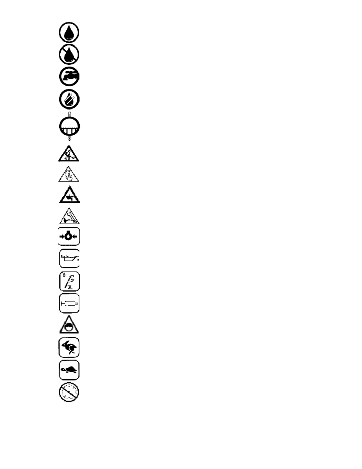
• Water Supply On.
• Suministro De Agua Conectado.
• Water Supply Off
• Suministro De Agua Desconectado
• Water Supply
• Suministro De Agua
• Water Safety Switch-Press to Reset if Water Supply Interrupted
• Si Se Ha Interrumpido El Suministro De Agua, Pulsar El Conmutador De Seguridad De Agua
Para Reposicionarlo.
• Coolant Temperature
• Temperatura Del Líquido Refrigerante
• Keep Work Area Clean/Well Lit, Remove All Safety Hazards
• Mantenga Limpio El Sitio De Trabajo/Bien Iluminado, Elimine Todos Los Riesgos De Seguridad
• Dangerously High Noise Level
• Nivel De Ruido Elevadamente Peligroso
• Pay Extreme Attention To The Care And Protection Of The Machine Before Starting Up
• Ponga Extrema Atención Al Cuidado Y Preparación De La Máquina Antes De Ponerla En Marcha
• Remove Tools From Area and Machine
• Elimine Las Herramientas Del Área Y De La Máquina
• Oil Pressure
• Presion De Aceite
• Oil Required
• Necesita Aceite
• Dipstick, Maintain Proper Oil Level
• Varilla De Control, Mantenga El Nivel De Aceite Correcto
• Lubrication Point
• Punto De Lubrication
• Always Keep the Blade Guards In Place
• Mantenga Siempre Las Protecciones De La Hoja En Su Sitio
• High Range Travel Speed
• Alta Velocidad De Avance
• Low Range Travel Speed
• Baja Velocidad De Avance
• Do Not Operate Without All Guards In Place
• No Operar Sin Todas Las Protecciones In Su Sitio
4
Page 5
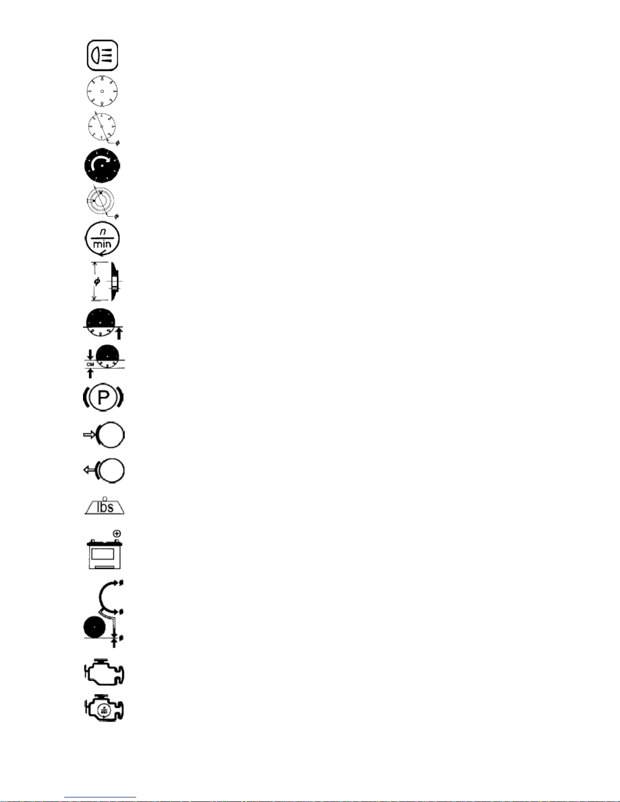
• Headlight
• Luz De Cruce
• Diamond Blade
• Sierra Diamantada
• Blade Diameter
• Diámetro De La Hoja
• Blade Engagement
• Acoplamiento De La Hoja
• Pulley Diameter
• Diámetro De La Correa
• Number of Revolutions Per Minute, Rotational Speed
• N° De Revoluciones Por Minuto, Velocidad De Rotación
• Blade Flange Diameter
• Diámetro De La Brida De La Hoja
• Blade Depth Stop
• Tope De Profundidad De La Hoja
• Blade Cutting Depth
• Profundidad De Corte De La Hoja
• Parking Brake
• Freno De Estacionamiento
• Parking Brake Applied
• Freno De Estacionamiento Aplicado
• Parking Brake Released
• Freno De Estacionamiento Suelto
• Machine Mass (lbs)
• Masa De La Máquina (lbs)
• Positive Battery Terminal
• Terminal Positivo De Batería
• Blade Indicator -Zero
• Indicador De Cero De La Hoja
• Engine
• Motor
• Engine Speed Revolutions/Minute
• Velocidad Del Motor En Revoluciones Por Minuto (RPM)
5
Page 6
• Engine Start
• Arranque Del Motor
• Repairs Are To Be Done By An Authorized Dealer Only
• Las Reparaciones Deben Ser Efectuadas Únicamente Por Un Distribuidor Autorizado
WARNING
HEARING HAZARD
DURING NORMAL USE OF THIS MACHINE, OPERATOR MAY BE EXPOSED TO A NOISE
LEVEL EQUAL OR SUPERIOR TO 85 dB (A)
ATENCION
RIESGO DE DAÑO AUDITIVO
EN CONDICIONES NORMALES DE UTILIZACIÓN, EL OPERADOR DE ESTA MÁQUINA PUEDE
ESTAR EXPUESTO A UN NIVEL DE RUIDO IGUAL O SUPERIOR A 85 dB (A)
DUST WARNING
Cutting, especially when DRY cutting, generates dust that comes from the material being cut, which
frequently contains silica. Silica is a basic component of sand, quartz, brick clay, granite and numerous other
minerals and rocks. Exposure to excessive amount of such dust can cause:
• Respiratory diseases (affecting your ability to breath), including chronic bronchitis, silicosis and pulmonary fibrosis from exposure to silica. These diseases may be fatal;
• Skin irritation and rash; and
• Cancer according to NTP* and IARC*
* National Toxicology Program, International Agency for Research on Cancer
Take precautionary steps
• Avoid inhalation of and skin contact with dust, mist and fumes;
• Wet cut when feasible, to minimize dust;
• Wear and ensure that all bystanders wear appropriate respiratory protection such as dust masks
designed to filter out microscopic particles. (See OSHA 29 CFR Part 1910.1200)
California Prop 65 Warning:
Use of this product can cause exposure to materials known to the State of California to cause cancer and/or
birth defects or other reproductive harm.
6
Page 7
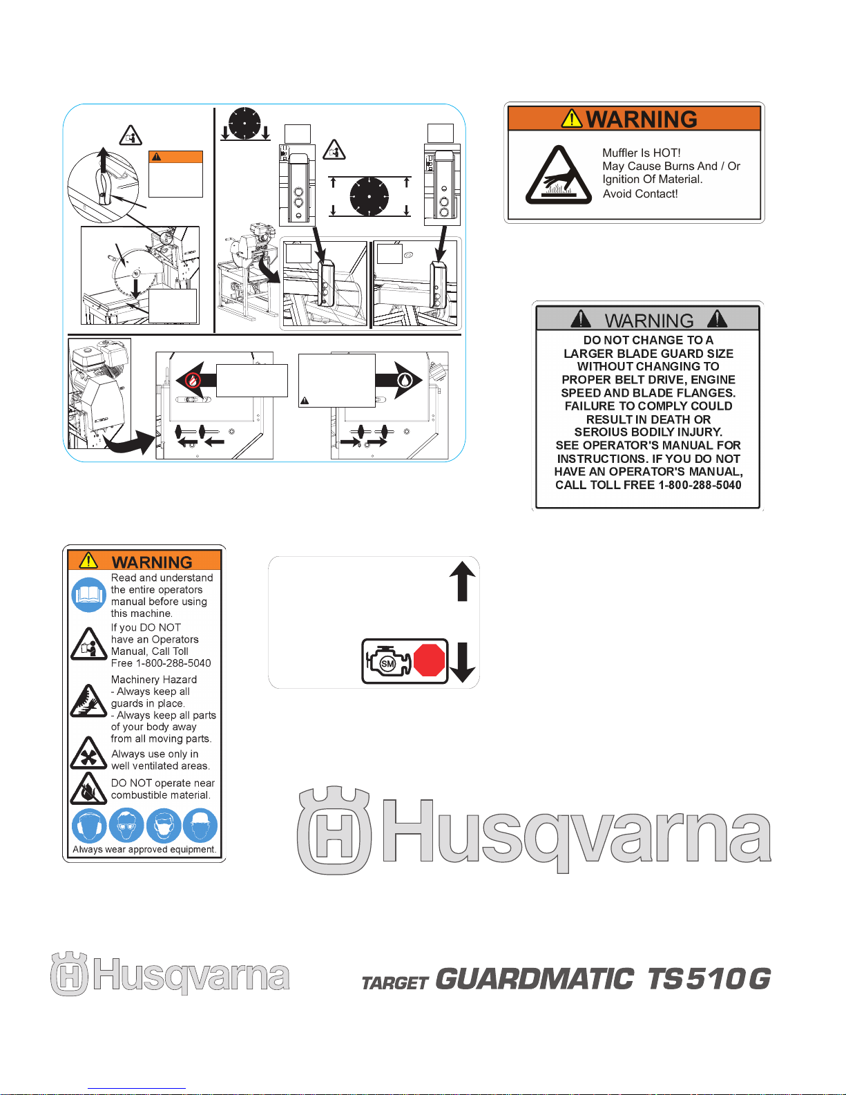
DECAL DESCRIPTIONS AND LOCATIONS
Read manual.
Lea el manual.
Veuillez lire le manuel.
Read manual.
Lea el manual.
Veuillez lire le manuel.
Lower Blade
Before Lifting
LIFTING EYE
LIFT
HERE
LIFTING
EYE
Only Use Lifting
Sling Approved
For Overhead
Lifting.
WARNING
WATER PUMP ENGAGEMENT
OFF
ON
DEPTH STOP ADJUSTMENT
0
14”
(355,6mm)
(508,0mm)
20”
14”
20”
20”
14”
14”
Secure Or
Remove
Conveyor Cart
Before Lifting
WATER PUMP OFF
1. Loosen Knobs.
2. Push Knobs Left.
3. Tighten Knobs.
WATER PUMP ON
1. Loosen Knobs.
2. Push Knobs Right
To Contact Belt.
3. Tighten Knobs.
Do NOT Run Pump Dry.
Switch Must Be
In “Start” (ON)
Position Before
Starting Engine.
STOP
PARADA MOTOR
STOP ENGINE
START
ARRANQUE
DESCRIPCIÓN DE CALCAMONIAS Y UBICACIONES
P/N 169065
Location: Rear of Engine Belt Guard
Location: Left Side of Engine Platform
P/N 177588
Warning Logo, Large
Location: Side of Bladeguard
P/N 542190415
P/N 542195324
Stop Switch Decal
Near Stop Switch on Cutting Head
P/N 046128
Warning Logo
Location: Front of Bladeguard
Location:
P/N 542190733 (2X)
Location: Front of Belt Guard, Front of Water Pan
P/N 542190725 (2X)
Location: Side of Water Pan
7
Page 8
SAFETY WARNINGS FOR OPERATION OF THIS MACHINE
WARNING!
FAILURE TO COMPLY WITH THESE WARNINGS AND OPERATING INSTRUCTIONS
COULD RESULT IN DEATH OR SERIOUS BODILY INJURY!
WARNING!
DO’s and DO NOT’s
DO Read this entire operator’s manual before operating this machine. Understand all warnings, instructions, and controls.
DO keep all guards in place and in good condition.
DO wear safety approved hearing, eye, head and respiratory protection.
DO read and understand all warnings and instructions on the machine.
DO read and understand the symbol definitions contained in this manual.
DO keep all parts of your body away from the blade and all other moving parts.
DO know how to stop the machine quickly in case of emergency.
DO shut off the engine and allow it to cool before refueling.
DO inspect the blade, flanges and shafts for damage before installing the blade.
DO use the blade flange size shown for each blade size.
DO use only reinforced abrasive blades or steel center diamond blades manufactured for use on concrete saws.
DO use only the blade flanges supplied with the saw. Never use damaged or worn blade flanges.
DO use only blades marked with a maximum operating speed greater than the blade shaft speed. Verify speed by checking
blade shaft rpm and pulley diameters and blade flange diameters.
DO verify saw drive configuration by checking blade shaft RPM, pulley diameters, and blade flange diameter.
DO read all safety materials and instructions that accompany any blade used with this machine.
DO inspect each blade carefully before using it. If there are any signs of damage or unusual wear, DO NOT USE THE
BLADE.
DO mount the blade solidly and firmly, wrench tighten the arbor nut.
DO make sure the blade and flanges are clean and free of dirt and debris before mounting the blade on the saw.
DO use the correct blade for the type of work being done. Check with blade manufacturer if you do not know if blade is cor-
rect.
DO use caution and follow the instructions when loading and unloading the machine.
DO operate this machine only in well ventilated areas.
DO instruct bystanders on where to stand while the machine is in operation.
DO establish a training program for all operators of this machine.
DO clear the work area of unnecessary people. Never allow anyone to stand in front of or behind the blade while the engine
is running.
DO make sure the blade is not contacting anything before starting the engine.
DO use caution when lifting and transporting this machine.
DO always tie down the machine when transporting.
DO use caution and follow instructions when setting up or transporting the machine.
DO have all service performed by competent service personnel
DO make sure power cords are the proper size and in good condition.
DO verify the blade arbor hole matches the machine spindle before mounting the blade.
DO always check for buried electrical cables before sawing. If unsure, contact the local utilities.
DO move the machine at least 10 feet (3 meters) from the fueling point before starting the engine and make sure the gas cap
on the machine and the fuel can is properly tightened.
DO lift only from the lift bail.
DO clean the machine after each day’s use.
DO follow all electrical codes in your area.
DO use correct voltage and proper extension cords. Never carry tool by cord or yank it to disconnect it from receptacle. Keep
cord away from heat, oil and sharp edges.
DO disconnect tools from power source when not in use, before servicing and when changing accessories.
DO carefully maintain and clean for better and safer performance. Follow instructions for changing accessories. Inspect tool
cords periodically and, if damaged, have repaired by authorized service facility.
DO use the proper blade flange size for each blade size. Never use damaged or worn blade flanges.
DO use caution when handling fuel.
8
Page 9
SAFETY WARNINGS FOR OPERATION OF THIS MACHINE
WARNING!
FAILURE TO COMPLY WITH THESE WARNINGS AND OPERATING INSTRUCTIONS
COULD RESULT IN DEATH OR SERIOUS BODILY INJURY!
WARNING!
DO’s and DO NOT’s
DO NOT operate this machine unless you have read and understood this operator’s manual.
DO NOT operate this machine without the blade guard, or other protective guards in place.
DO NOT stand behind or in front of the blade path while the engine is running.
DO NOT leave this machine unattended while the engine is running.
DO NOT work on this machine while the engine is running.
DO NOT operate this machine when you are tired or fatigued.
DO NOT use a wet blade without adequate water supply to the blade.
DO NOT exceed maximum blade speed shown for each blade size. Excessive speed could result in blade breakage.
DO NOT operate the machine if you are uncertain of how to run the machine.
DO NOT use damaged equipment or blades.
DO NOT touch or try to stop a moving blade with your hand.
DO NOT cock, jam, wedge or twist the blade in a cut.
DO NOT transport a cutting machine with the blade mounted on the machine.
DO NOT use a blade that has been dropped or damaged
DO NOT use carbide tipped blades.
DO NOT touch a dry cutting diamond blade immediately after use. These blades require several minutes to cool after each
cut.
DO NOT use damaged or worn blade flanges.
DO NOT allow other persons to be near the machine when starting, refueling, or when the machine is in operation.
DO NOT operate this machine in an enclosed area unless it is properly vented.
DO NOT operate this machine in the vicinity of anything that is flammable. Sparks could cause a fire or an explosion.
DO NOT allow blade exposure from the guard to be more than 180 degrees.
DO NOT operate this machine with the belt guard or blade guard removed.
DO NOT operate this machine unless you are specifically trained to do so.
DO NOT use a blade that has been over heated (core has a bluish color).
DO NOT jam material into the blade.
DO NOT grind on the side of the blade.
DO NOT lay power cords in or near the water.
DO NOT tow this machine behind a vehicle.
DO NOT leave the machine unattended with the motor running.
DO NOT replace the motor with any motor that does not have a special grounding connection
DO NOT use the tie down brackets for lifting this machine.
DO NOT operate this machine with the transmission guard removed.
DO NOT cut deeper than 1” per pass with a dry blade. Step cut to achieve deeper cuts.
DO NOT operate this machine while using drugs or alcohol.
This machine was designed for certain applications only. DO NOT modify this machine or use for any
application other than for which is it was designed. If you have any questions relative to its application,
DO NOT use the machine until you have written to us and we have advised you.
Husqvarna Construction Products
17400 West 119th Street
Olathe, Kansas 66061, USA
9
Page 10
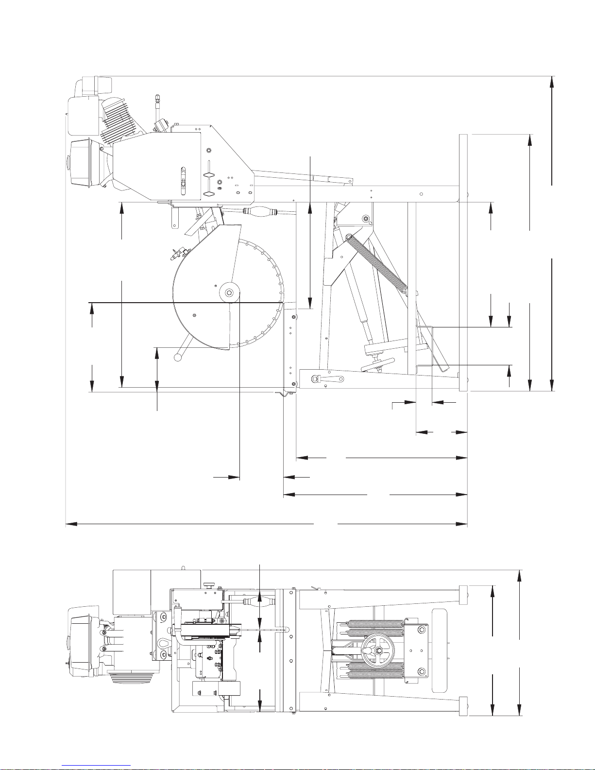
47.50” (1206mm)
58.22” (1479mm)
15.05”
(382mm)
7.45”
(189mm)
74.27”
(1886mm)
8.00 - 22.38” - 20”
(203 - 568mm) - 20”
4.36 - 22.38” - 14”
(111 - 568mm) - 14”
8.22 - 10.58” - 20”
(208 - 269mm) - 20”
11.22 - 13.58” - 14”
(285 - 345mm) - 14”
16.53”
(420mm)
34.00”
(864mm)
31.63”
(803mm)
24.06”
(611mm)
26.96”
(685mm)
7.00”
(178mm)
23.13” (587mm)
34.25”
(870mm)
19.73”
(501mm)
3.00”
(76mm)
9.50”
(241mm)
Guardmatic Dimensions
10
Page 11
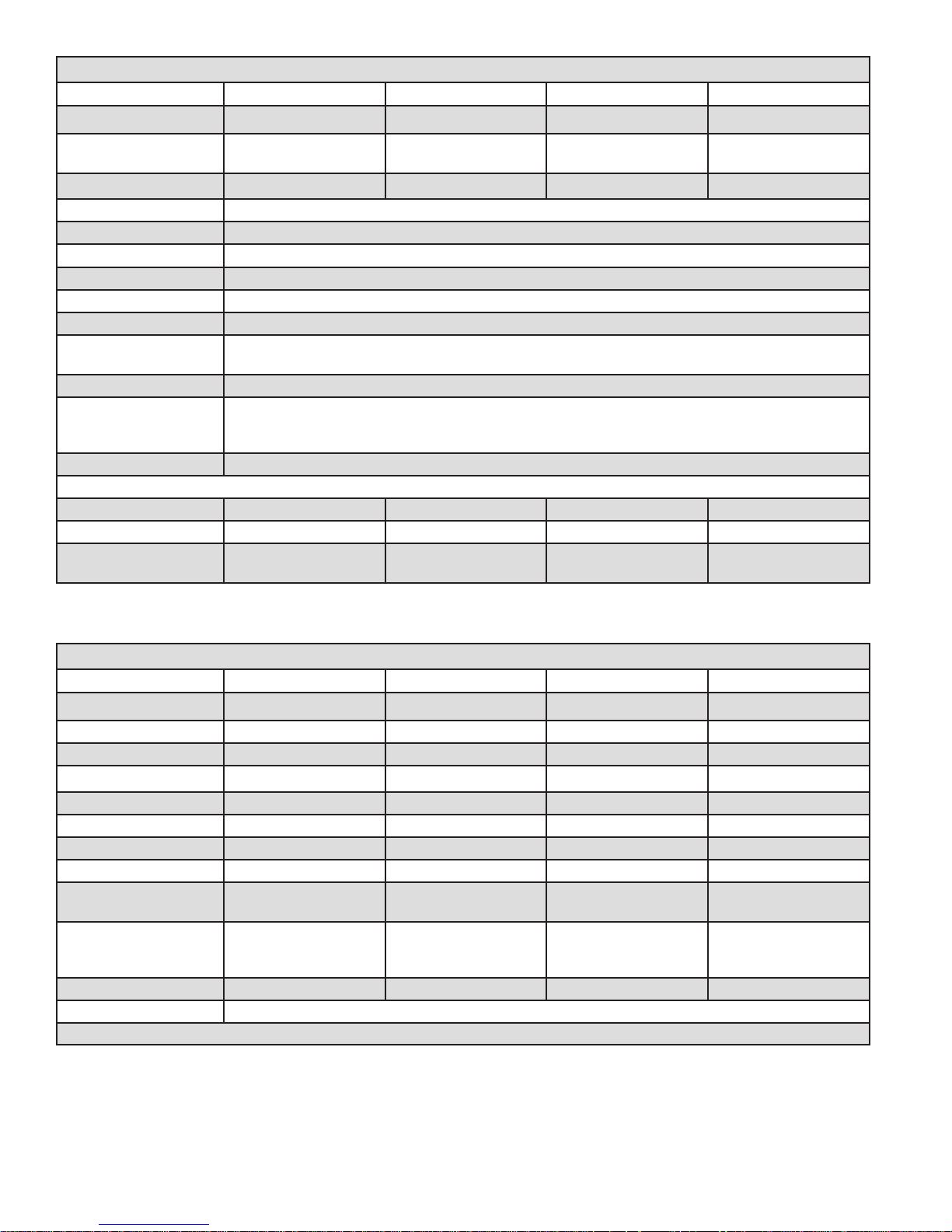
Specications
MODEL 9 HP 9 HP w/ Clutch 13 HP 13 HP w/ Clutch
TYPE Gasoline Engine Gasoline Engine Gasoline Engine Gasoline Engine
Blade Guard
Capacity
Blade Shaft RPM: 2300 2300 2300 2300
Max. Depth of Cut: 8.0" (203 mm)
Blade Arbor Size: 1.00" (25.4 mm)
Blade Shaft: Sealed Ball Bearings
Blade Shaft Drive: Two 3VX475 V-Belts
Blade Guard: One Piece Steel, Sta-LevelTM Design, 20" (500 mm) Maximum Capacity
Blade Coolant: Water
Water Pan:
Conveyor Cart: Cast Aluminum w/ Vulcanized Rubber Top, Adjustable Measuring Rule, 45° / 90° Cutting Guide
Water Pump:
Electric Models:
Gasoline Model:
Frame: Heavy duty, Jig Welded “X” Braced Steel, Open Throat Design For Unlimited Ripping
Weight Pounds (kg):
Saw Crated: 488 (221.3) 492.5 (223.3) 501.3 (227.4) 505.8 (229.4)
Saw Uncrated: 468 (212.3) 472.5 (214.3) 481.3 (218.3) 485.8 (220.3)
Saw Operating
(Water in Pan):
14 - 20"
(350 - 500 mm)
21.73 x 36.73 x 3.50 Inch (552x933x88.9 mm), 13.1 Gallon (49.6 Liter) Capacity
300 Gallons / Hour, Submersible, Totally Epoxy Sealed, Thermal Over Load Protected
8 GPM, Belt Drive, Solid Bronze, With Strainer & Built-In Priming Pump with Check Valve
577 (261.7) 602 (273.1) 611 (277.1) 615 (279)
14 - 20"
(350 - 500 mm)
[1” (25.4 mm) From Top)
14 - 20"
(350 - 500 mm)
14 - 20"
(350 - 500 mm)
Power Source
MODEL 9 HP 9 HP w/ Clutch 13 HP 13 HP w/ Clutch
TYPE: Gasoline Gasoline Gasoline Gasoline
Engine / Motor: Honda Honda Honda Honda
Horsepower (kw): 9 (6.7) 9 (6.7) 13 (9.7) 13 (9.7)
RPM: 3750 3750 3750 3750
Displacement: 14.8 cu. Inch (270 cc) 14.8 cu. Inch (270 cc) 23.7 cu. Inch (389 cc) 23.7 cu. Inch (389 cc)
Bore: 3.0 inch (77mm) 3.0 inch (77mm) 3.5 inch (88mm) 3.5 inch (88mm)
Stroke: 2.3 inch (58mm) 2.3 inch (58mm) 2.5 inch (64mm) 2.5 inch (64mm)
Cylinders / Cycle: 1/4 1/4 1/4 1/4
Fuel Capacity:
Air Filter:
Starter: Recoil Recoil Recoil Recoil
Cooling System: Air
1.59 U.S. Gallon
(6.0 liter)
Dry Type
Dual Element
with Pre-cleaner
1.59 U.S. Gallon
(6.0 liter)
Dry Type
Dual Element
with Pre-cleaner
1.72 U.S. Gallon
(6.5 liter)
Dry Type
Dual Element
with Pre-cleaner
1.72 U.S. Gallon
(6.5 liter)
Dry Type
Dual Element
with Pre-cleaner
11
Page 12
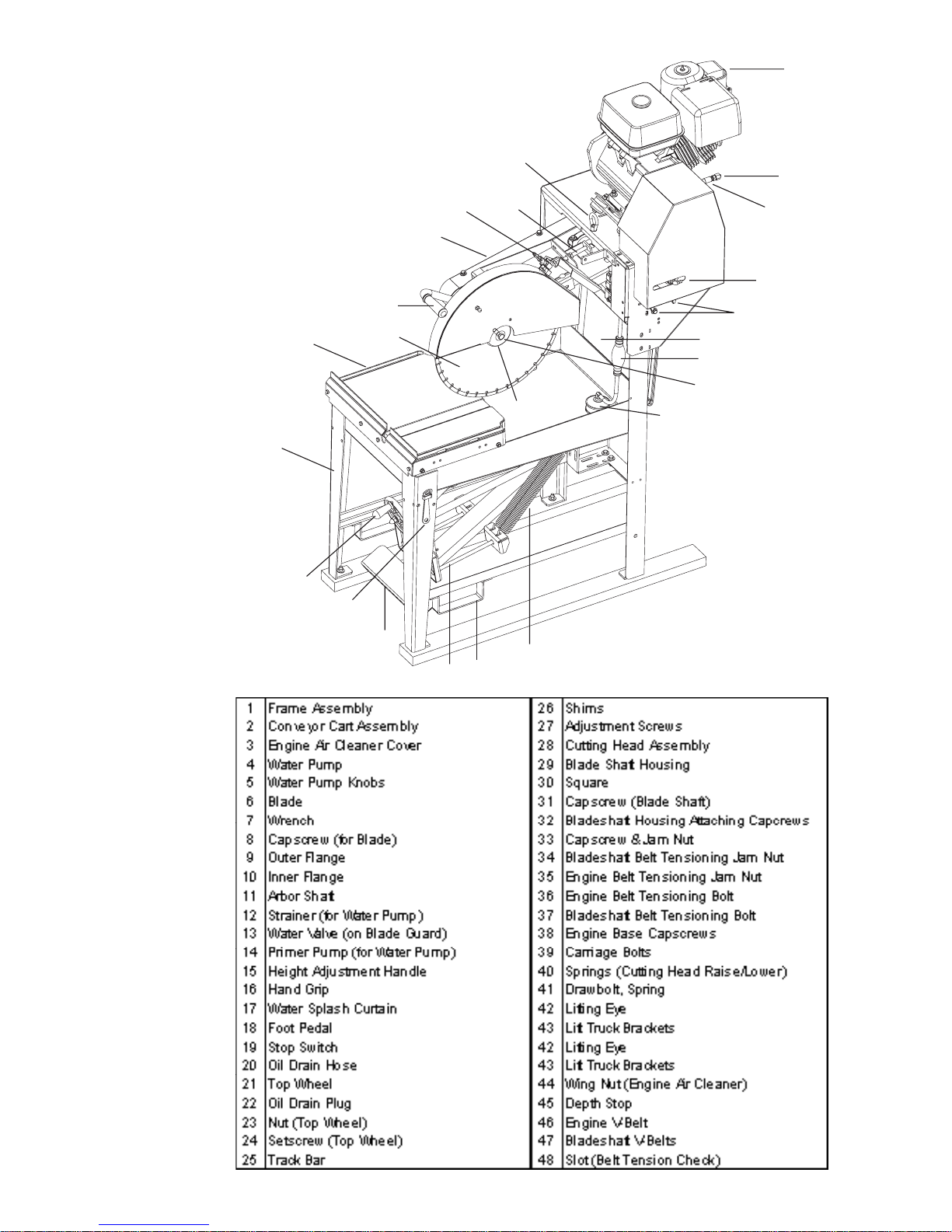
3
20
22
4
5
17
14
8
42
37
13
28
16
6
1
15
7
18
41
40
2
9
12
43
Parts Identification:
12
Page 13
•Mandatory
3
44
2
1
•Obligatorio
•Prohibition
•Prohibición
Any persons not involved in the work,
should leave the area.
•Indication
•Indicación
These signs will give advice for your safety.
Before leaving our factory every machine
is thoroughly tested.
Follow our instructions strictly and your machine
will give you long service in normal operating conditions.
•Warning Triangle
•Triángwulo De
Advertenciao
1. Features
Use: Wet or Dry sawing of masonry and refractory.
Tools: Diamond blades -- dry or water cooled,
Ø: 14” (350 mm), and 20” (500 mm)
with Arbor Ø 1” (25.4 mm).
Depths of Cut (Maximum):
8.00” (127 mm) with Ø 20” (500 mm) blade
Maximum material Size:
8 x 8 x 16” (20,3 x 20,3 x 40,6 cm) block
WARNING!
Use only blades marked with a maximum operating speed greater than the blade shaft speed.
2. Assembly
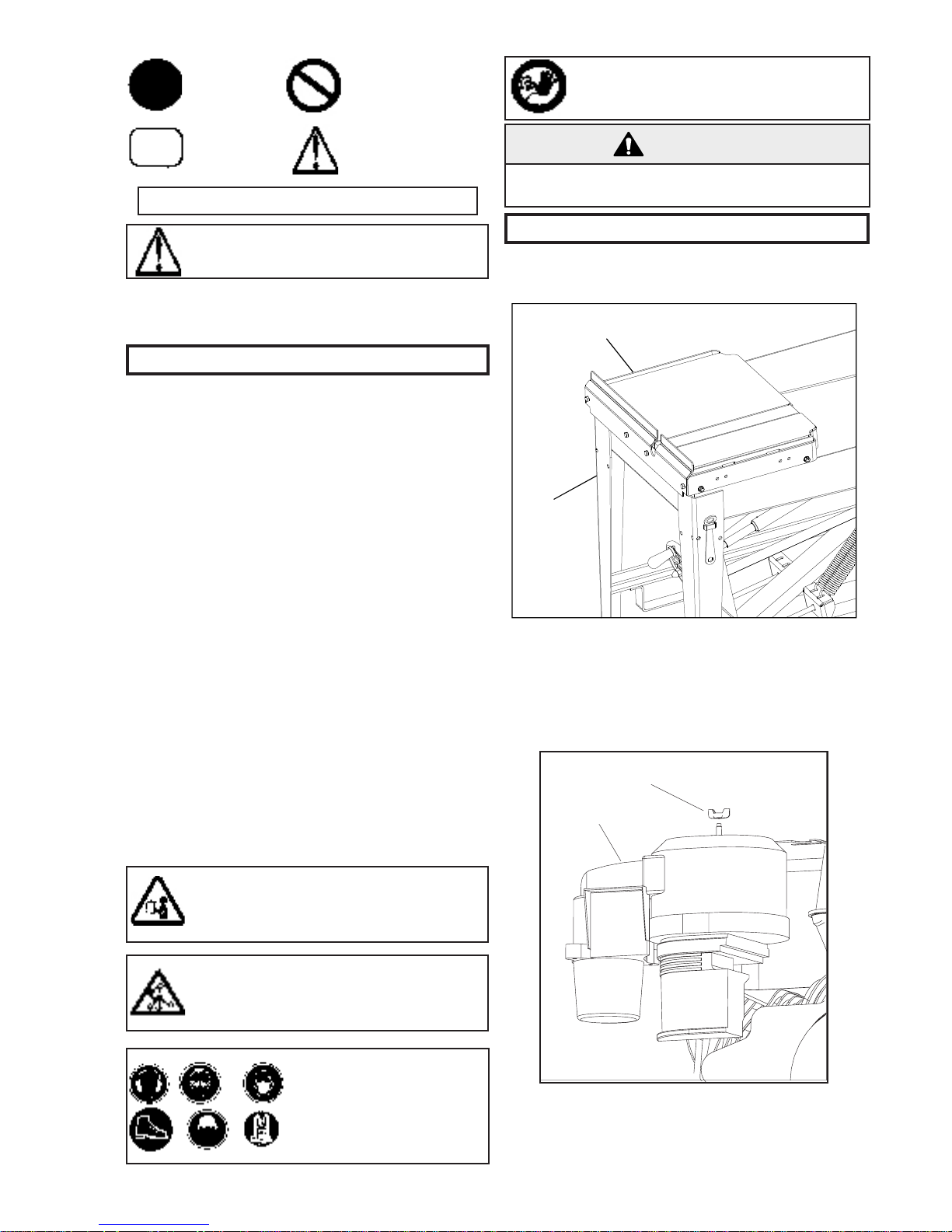
When unpacked, this unit consists of three (3) parts:
Frame Assembly (1), Conveyor Cart Assembly (2),
Engine Air Cleaner Cover (3).
Nominal Weight: See “Specifications”
Operating Weight: See “Specifications”
Dimensions: See “Saw Dimensions”
Blade Guard Capacity:
14” (350 mm), 18” (450 mm), and 20” (500 mm) Ø.
Smaller Blade Diameter not recommended because
blade will not contact the conveyor cart. Head tilt is
limited by the depth stop, which also prevents cutting through the conveyor cart when the blade is in
the lowest position.
Blade Shaft RPM: See “Specifications”
Before starting up machine make
sure you read these instructions and
are familiar with the operation of this
machine.
The working area must be completely
clear, well lit and all safety hazards
removed (no water or dangerous
objects in the vicinity).
The operator must wear
protective clothing appropriate to the work he is
doing. We recommend
hearing, respiratory and
eye protection.
Remove the Conveyor Cart Assembly (2) from its
shipping carton. Set it onto the Frame Assembly (1)
so that the wheels of the Conveyor Cart Assembly
(2) roll along the sides of the Frame Assembly (1).
Remove the Engine Air Cleaner Cover (3) and
install it onto the engine using the Wing Nut (44)
that is loosely installed above the engine air cleaner
element.
13
Page 14
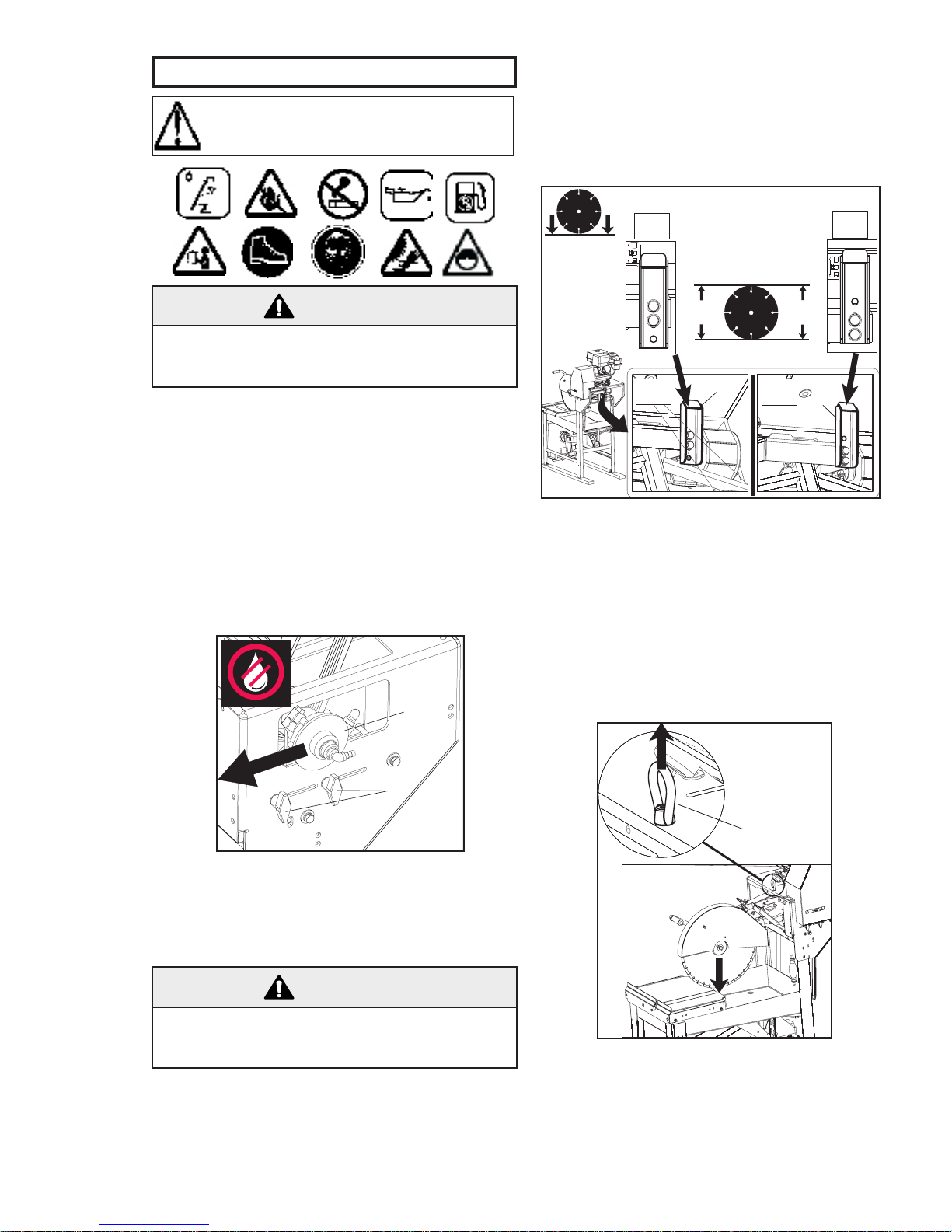
3. Check Before Operating
4
5
DEPTH STOP ADJUSTMENT
0
14”
(355,6mm)
(508,0mm)
20”
14”
20”
20”
14”
14”
45
45
42
Take into account the working conditions from a health and safety point of
view.
CAUTION!
Engine inclination angles greater than 20 degrees
could cause severe engine damage and void your
engine warranty!
• Engine Fuel: Check the engine operation manual. Unleaded gasoline is recommended.
• Engine Oil: With the Frame Assembly (1) positioned so that the engine is in a horizontal position, check that the engine oil level is correct.
Check the oil level frequently to ensure that
the level never falls below that specified in the
engine operation manual. If the oil level is low,
add SAE 10W30, service classification SF or SG
oil (for normal conditions) as recommended in
the engine operation manual. DO NOT overfill
engine with oil!
blades are to be used, the depth stop must be set
for 14” (350mm) blades. The depth stop will not
function properly for 18” (450mm) blades because
the blade will cut into the Conveyor Cart Assembly if
the operator does not take care.
To adjust the depth stop for a new blade diameter,
remove the attaching hardware, move the Depth
Stop (45) to the desired position, as shown above,
then re-install the attaching hardware.
Moving the machine:
The machine can be moved two ways:
1. By using the Lift Truck Brackets (43), a fork
truck can be used to lift the machine. Simply
slip one fork through the brackets on the front
lower part of the Frame Assembly (1).
Make sure that the Water Pump (4) is disengaged
before starting the engine. If it is not in the position
shown above, loosen the Water Pump Knobs (5)
and push all the way to the left (belt Guard moved
for clarity purposes only).
CAUTION!
DO NOT run Water Pump (4) for extended periods
of time without water! Water Pump (4) could be
damaged!
Blade Depth Stop:
This machine is equipped with an adjustable stop
that prevents the Blade (6) from cutting into the
Conveyor Cart Assembly (2). The Depth Stop (45)
2. By using the Lifting Eye (42), a lifting sling
can slipped through the Eye, and along with a
lift truck or a crane, the machine can be easily moved. The Cutting Head Assembly (28)
should be lowered as much as possible to avoid
hitting the lifting sling when the machine is
lifted.
14
Page 15
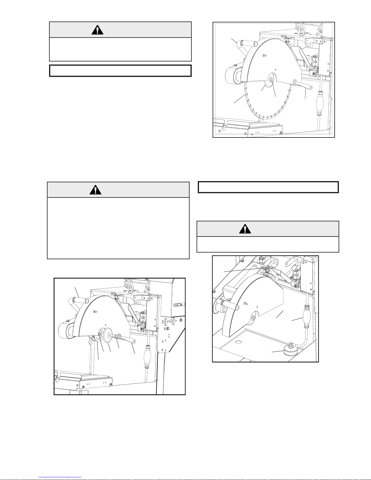
16
10
11
9
8
7
16
6
9
8
7
13
17
14
12
WARNING!
Only use Lifting Sling approved for overhead lifting. Using Improper Lifting Sling can result in injury or death of operator or persons in work area!
4. Fitting The Blade
• The blade rotates in a “down-cut” direction. This
means that the front of the blade is moving
downward while the rear of the blade is moving
upward. Mount the Blade (6) so that the arrow
on the blade rotates in this “down-cut” direction.
The Blade (6) can be installed or removed by
using the 3/4” (19 mm) end of the Wrench (7)
provided.
• After mounting the Blade (6), it should align over
the top of the wooden insert in the Conveyor
Cart (2). During operation of this unit, the blade
should pass into the wooden insert, but NOT into
the cast aluminum part of the Conveyor Cart (2).
3. Mount the Blade (6) to the Arbor Shaft (11) and
install the Outer Flange (9). Install and tighten
Capscrew (8) by turning it in a Clockwise direction (Right Hand Thread). Use the Wrench (7)
to firmly tighten the Capscrew (8) to the arbor
shaft.
WARNING!
Use only Abrasive blades of a reinforced type.
Never use an abrasive blade with water.
Conventional “Wet” diamond blades MUST be
used with water.
DO NOT use conventional “Wet” diamond blades
without water. Using conventional “wet” diamond
blades without water can result in injury or death of
the operator or persons in the work area!
Mounting the Blade (6):
5. Operating Instructions
Configure the saw for wet or dry operation. Note
that the saw is factory assembled for dry operation.
Wet Operation:
WARNING!
Use only Abrasive blades of a reinforced type.
Never use an abrasive blade with water.
1. Using the Wrench (7) provided (or one of your
own) loosen the Capscrew (8) by turning it
Counter-Clockwise.
2. Remove the Outer Flange (9) and make sure
the Outer Flange (9), the Inner Flange (10), and
Arbor Shaft (11) are clean and not damaged.
Fill the water reservoir pan [of the Frame Assembly
(1)] with water to within 1 inch (25 mm) of the top.
Be sure that the water pump intake Strainer (12) is
fully immersed in water at all times. Keep the intake
screen clean and free of sludge, slurry, or other foreign material.
Make sure the Water Valve (13) on the blade guard
is in the open position (Lever parallel with valve
body). Squeeze the Primer Pump (14) until water
flows out of the blade guard water tubes. Adjust the
water flow with the Water Valve (13), and check the
water flow before cutting.
15
Page 16
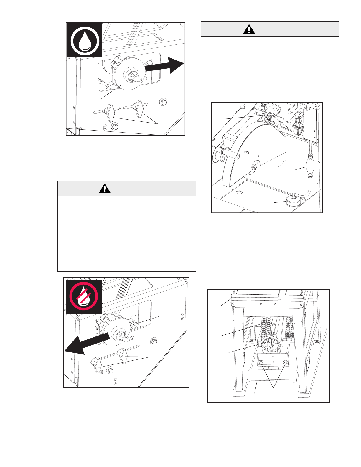
13
17
14
12
2
40
15
18
41
Make sure that the Water Pump (4) is engaged
4
5
4
5
before cutting material. If the Water Pump (4) is
not in the position shown above, loosen the Water
Pump Knobs (5) and push all the way to the right.
Dry Operation:
WARNING!
Conventional “Wet” diamond blades MUST be
used with water. DO NOT use conventional “Wet”
diamond blades without water. Using conventional “wet” diamond blades without water can result
in injury or death of the operator or persons in the
work area!
When cutting without water use only diamond
blades that are intended to be used dry (without water). Conventional “Wet” diamond blades
MUST be used with water.
CAUTION!
DO NOT run the WATER PUMP (4) for extended
periods of time without water! The WATER PUMP
(4) could be damaged!
• Hint: To reduce vibration of the saw, the water
reservoir pan [of the Frame Assemble (1)] can
be filled with sand. Be sure to remove the water
pump intake Strainer (12) to avoid contaminating
it with dirt or sand.
Remove the Water Splash Curtain (17) so that dust
flow freely out the back of the saw. The saw is now
ready for dry cutting.
Cutting Operations:
Cutting Methods: This unit allows three methods for
the blade to contact the material:
Make sure that the Water Pump (4) is disengaged
before starting the engine. If it is not in the position
shown above, loosen the Water Pump Knobs (5)
and push all the way to the left.
1. Fixed Head Cutting Method:
Position the head to the desired height by turn-
ing the Height Adjustment Handle (15). When
the desired height is reached, stop turning the
handle and the cutting head will remain in position.
16
Page 17
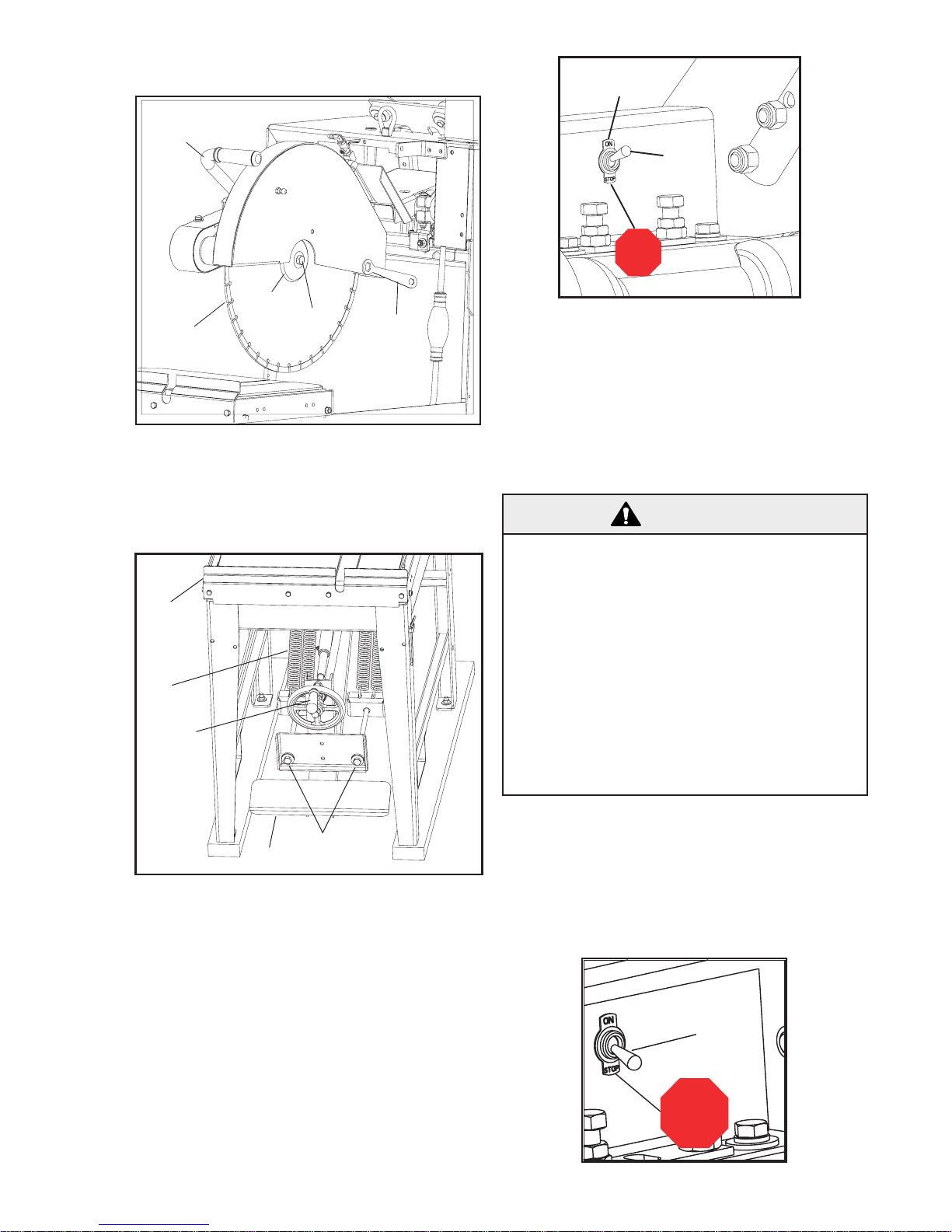
2
40
15
18
41
STOP
START (ON)
19
STOP
19
2. Hand Controlled Cutting Method:
16
6
9
8
7
Hold the Hand Grip (16) and lower the blade
into the material. The blade will return to the
upper position when force is released from the
Hand Grip.
Start the engine by using the procedure in the
engine operation manual. Make sure that the
Stop Switch (19) is in the “START” (On) Position
before using the engine starting rope. Open the
engine throttle full open. All sawing is done at full
throttle. Do Not change the engine governor setting
-- it is factory set for the correct speed. See the
“Specifications” section of this document for proper
engine & blade shaft RPM.
3. Foot Controlled Cutting Method:
Push the Foot Pedal (18) using your foot, and
the blade is lowered into the material. The
blade will return to the upper position when
force is released from the foot pedal.
After the Cutting Method has been determined,
move Conveyor Cart (2) to the front of the
saw so that the blade DOES NOT contact the
material, then place material on Conveyor Cart
Assembly (2).
WARNING!
Keep hands clear of rotating blade during operation. READ ALL SAFETY WARNINGS before
operating this machine.
Conventional “Wet” diamond blades MUST be
used with water. DO NOT use conventional “Wet”
diamond blades without water. Using conventional “wet” diamond blades without water can result
in injury or death of the operator or persons in the
work area!
When cutting without water use only diamond
blades that are intended to be used dry (without water). Conventional “Wet” diamond blades
MUST be used with water.
Cut the material using one of the Cutting Methods
described in the above section. Gently push the
material into the blade. When the material is completely cut, return the conveyor cart to the original
position.
Stopping the Unit:
Starting and Stopping:
After determining if the material will be cut wet or
dry, and the deciding on the cutting method, the
engine can now be started.
17
Page 18
Stop the unit by putting the Stop Switch (19) into
the “Stop” (Off) position. Wait for all blade movement to stop before removing material from the
machine.
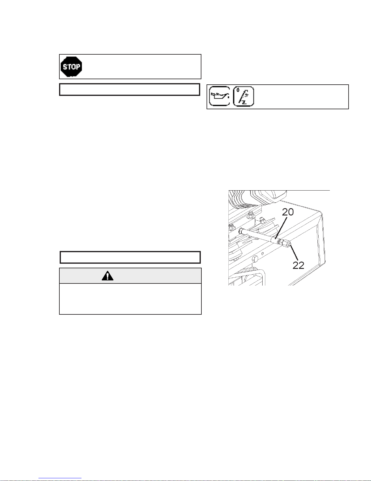
• Check engine oil daily. Change engine oil after
every 50 hours of operation. Engine Oil capacity
is shown below. See engine operation manual
for proper care and maintenance.
Emergency: In an emergency situation
turn the Stop Switch (19) to the STOP
(OFF) position.
6. Incidents During Operation
• If the engine or motor stops during sawing,
check the following:
1. Out of fuel: Check fuel level.
2. Low Oil Level: This unit is equipped with a
shut down system that stops the engine if
a low oil level is encountered. Check the
engine oil level while the engine is in a horizontal position.
• If the engine or blade stalls for any reason, raise
the blade completely out of the cut, inspect the
machine thoroughly before restarting. When
lowering the blade into a partial cut, align the
blade exactly with the cut to prevent damage to
the blade.
• Excessively fast cutting will stall the engine.
• If the blade stops during sawing check that the
drive belt tension is adequate.
Every 50 Hours:
• Change Engine Oil:
Change Engine Oil: Change
engine oil after every 50 hours of
operation.
Engine Oil Type:
Under normal operating conditions use SAE 10W30
API service classification SF or SG. See engine
operation manual for other recommended oil types.
Engine Oil Capacity (9hp & 13hp Honda):
1.16 U.S. Quarts, 1.1 Liters.
Engine Oil Change Procedure:
7. Maintenance
WARNING!
Before performing any maintenance, ALWAYS
locate the machine on a level surface with the
engine OFF, and the Stop switch in the OFF position.
Check Daily:
• Clean the reservoir pan [of Frame Assembly
(1)] to remove sludge and slurry. This concrete
slurry is an abrasive cutting compound and will
shorten the life of the Water Pump (4) and the
Diamond Blade (6). Clean the reservoir pan
twice a day in heavy cutting. Then refill the
water reservoir pan with clean water.
• At the end of each day clean the water reservoir
pan [of Frame Assembly (1)] to remove sludge
from the saw. Flush clean water through the
Water Pump (4) and hoses.
• Check engine air cleaner daily! If cutting dry
check engine air cleaner every four hours! Clean
or replace air cleaner element as recommended
by the engine manufacturer.
1. Drain the oil while the engine is still warm to
assure rapid and complete oil drain. Place a
bucket under the Oil Drain Hose (20) to catch
the used oil. Remove the Oil Drain Plug (22) on
the end of the Oil Drain Hose (20) and wait for
all of the used oil to be drained for the engine.
2. Re-install and securely tighten the Oil Drain
Plug (22).
3. Re-fill engine with the recommended oil type.
See the engine operation manual for the oil
fill location and proper oil level. Note that the
required oil capacity will be larger because of
the volume of oil contained in the Oil Drain
Hose (20).
4. Re-install the oil fill cap after filling engine with
oil.
5. Dispose of the used oil in a proper container
and in a manner that is compatible with the
environment.
18
Page 19
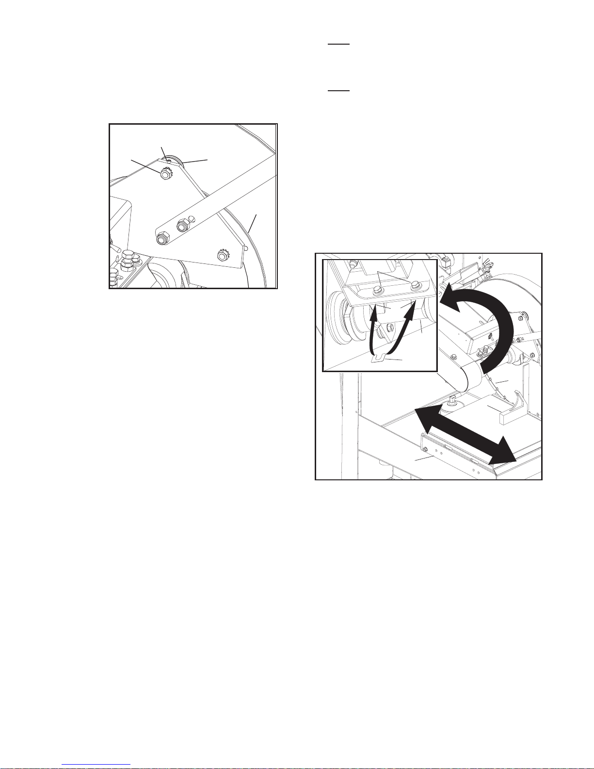
When Required:
23
24
21
25
6
30
2
31
A1
29
26
• “Sta-Level” Blade Guard: If the blade guard
becomes loose and pivots too freely the blade
guard rotation can be tightened. Adjust the Top
Wheel (21) of the three (3) wheels behind the
blade guard:
1. Loosen the NUT (23) holding the Top Wheel
(21) in position.
• Note: Before starting to align the head platform
make sure the blade is flat and is NOT bent or
damaged!
• Note: When aligning the blade against the
square be sure to allow for the difference in
thickness between the diamond segment and the
center core of the blade!
Blade Alignment:
1. Make sure the Conveyor Cart Assembly (2)
rolls freely along the pan. If the pan is damaged it must be repaired or replaced before the
blade can be aligned. Adjust the Cutting Head
Assembly (28) so that the Blade (6) is lowered
to the Conveyor Cart (2).
2. Adjust the Setscrew (24) to force the Top Wheel
(21) down against the Track Bar (25).
3. Re-tighten the Nut (23) holding the Top Wheel
(21) in position.
• Blade Shaft Housing Replacement and Blade
Alignment: The blade shaft arbor on this
machine is aligned at the factory so that a new
blade will cut “square” with the material placed
on the Conveyor Cart Assembly (2). There are
two reasons that a blade could be out of alignment:
1. If the Blade Shaft Housing (29) or Blade
Shaft Assembly needs to be replaced. If
this is the case, take note of the position
and quantity of Shims (26) behind the
blade shaft Assembly before completely
removing it from the saw. If the shims
are placed back in position when the new
Blade Housing Assembly (29) is installed
there is normally no reason to re-align the
blade. If this is not the case, follow the
alignment procedure shown below.
2. If the saw is dropped or damaged, the
blade could become mis-aligned so that it
no longer cuts “squarely” through the material. If this occurs the blade shaft should
be re-aligned so that the saw will produce
“square” cuts. If the Blade is severely out
of alignment [1/16” (1.5 mm)
or more] parts of the Cutting Head assem-
bly (28) may need to be replaced. Precise
alignment can be achieved by using
the Adjustment Screws (27) and/or Shims
(26) and following the procedure.
2. Parallel Alignment: Supply a Square (30) and
place it on the Conveyor Cart Assembly (2) as
shown in the diagram above. Roll the Conveyor
Cart Assembly (2) while the Square (30) rests
against the blade. Adjust the Blade Shaft into
Parallel Alignment (if required) by putting Shims
(26) between the vertical surface behind the
Blade Shaft Housing (29) and Head Platform
Weldment at location “A1” shown on the diagram above. Loosen, but do not remove, the
Capscrews (31) holding the blade shaft in position. Slide a Shim (26), of the proper thickness,
upward and position around the thread of ONE
of the capscrews. Tighten the hardware and
check the blade alignment. Add more shims if
required until until the gap between the Blade
(6) and the Square (30) is minimized, and consistent over the entire length that the Conveyor
Cart (2) travels.
19
Page 20
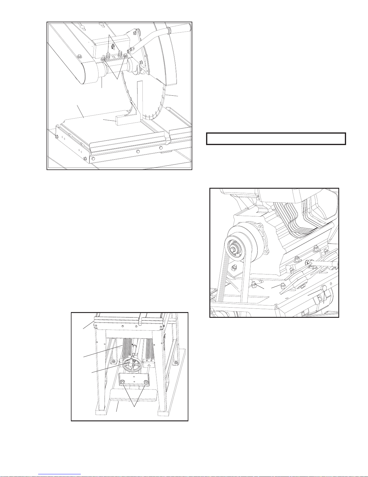
33
32
29
2
30
6
3. Perpendicular Alignment: Place the Square (30)
2
40
15
18
41
38
36
35
on the Conveyor Cart Assembly (2) so that it
is against the saw Blade (6) and is below the
center of the blade shaft. If the Square (30)
does NOT contact the Blade (6) along the
entire height of the square, the blade shaft must
adjusted into Perpendicular Alignment. Adjust
the Blade Shaft Housing (29) by adjusting the
Capscrews And Jam Nuts (33) of the Horizontal
surface of the Cutting Head Assembly. First
loosen the Blade Shaft Housing Attaching
Capscrews (32), then tighten ONE of the
Capscrews (33) until the Square and the
Blade (6) contact along the entire length of the
Square. Tighten down the corresponding Jam
Nut (33), the tighten the Blade Shaft Housing
Attaching Capscrews (32). Next, gently tighten
down the remaining Capscrew and Jam Nut
(33) just firmly enough so that it does not loosen during use.
Assembly (2) downward, the Springs (40) should
be loosened so that they become shorter in length.
To do this, turn each of the Drawbolts (41) CounterClockwise until the desired pivot force is achieved.
Cutting Head Assembley Does Not Raise
Properly: If the Cutting Head will not pivot to the
maximum upper position, then the Springs (40)
need to be tightened so that they become longer
in length. This could be required a few days after
using a new saw when it becomes covered in
dirt and concrete slurry. To do this, turn each of
the Drawbolts (41) Clockwise so the spring force
increases until the desired force is achieved.
8. V-Belt Tension
• The saw is equipped with high tension V-Belts.
The belts are properly tensioned at the factory, but after a few hours of operation they will
stretch and become loose.
Tensioning Engine V-Belts (46):
• Raise-Lower of the Cutting Head Assembly (2):
Cutting Head Assembly Is Hard To Lower:
If excess force required to pivot the Cutting Head
The Engine V-Belt (46) is a “Banded” type 3VX belt.
Supplied with each replacement belt is “tension
strip” that can be used to check the tension of this
belt while installing on the saw.
1. If this belt needs to be tensioned, loosen,
but do not remove, the four (4) Engine Base
Capscrews (38) that hold the engine platform in
place.
2. Loosen the Engine Belt Tensioning Jam Nut
(35) on the rear underside edge of the engine
platform.
3. Tighten the Engine Belt Tensioning Bolt (36)
until the proper belt tension is achieved.
4. Re-tighten the Engine Belt Tensioning Jam Nut
(35), and the four (4) Engine Base Capscrews
(38).
20
Page 21
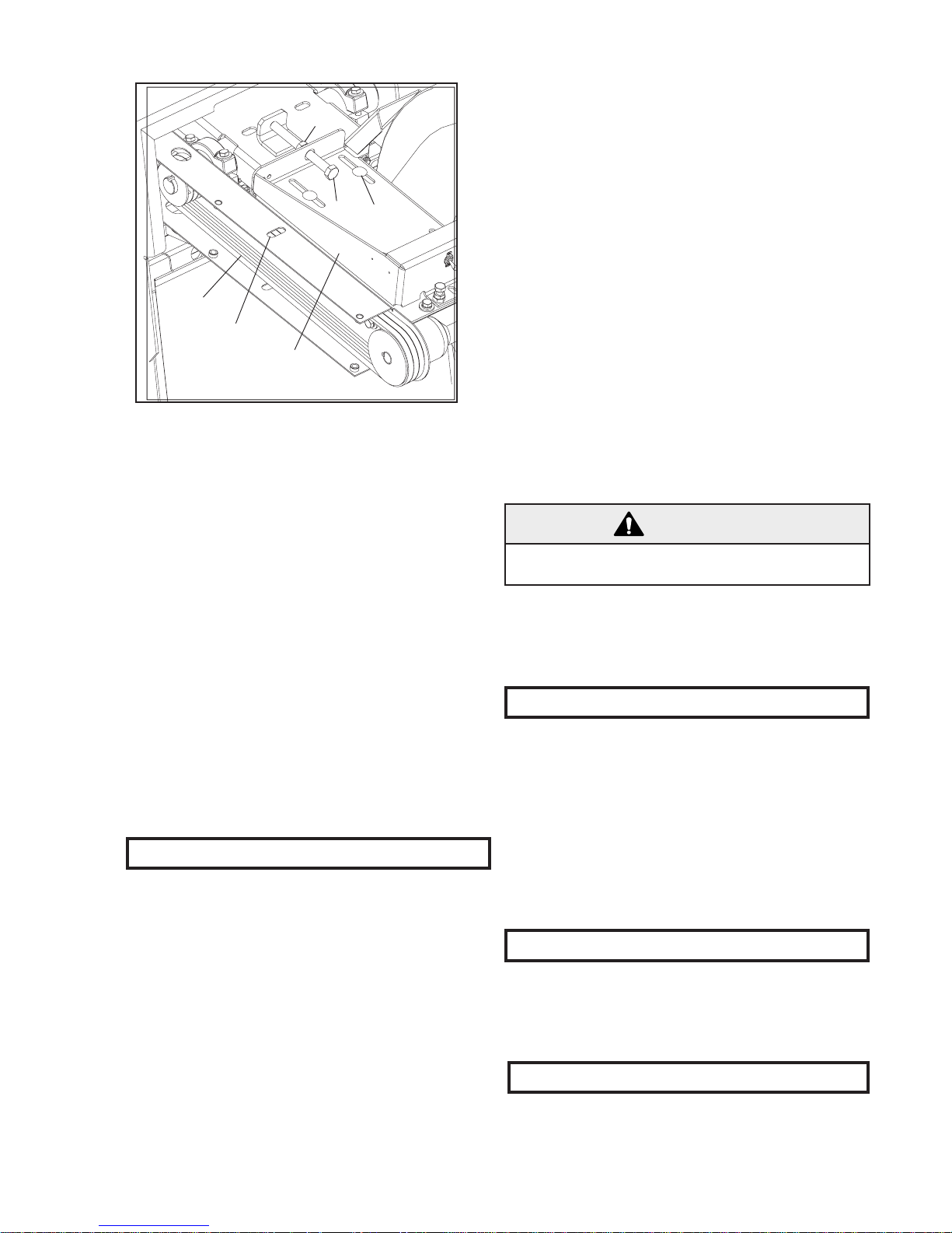
Tensioning Blade Shaft V-Belts:
47
48
28
39
37
34
The blade shaft V-Belts are standard “single
groove” 3VX belts. Check the tension in these belts
when the unit is new and never set the belt tension
beyond this point. Belt tension can be checked with
a standard belt tension gauge through the Slot (48)
in the inner belt guard.
1. Remove Belt Guard.
2. If these belts need to be tensioned, loosen, but
do not remove, the six (6) Carriage Bolts (39)
that hold front of the Cutting Head Assembly
(28) to the rear section of that same assembly.
3. Loosen the Bladeshaft Belt Tensioning Jam Nut
(34) on the Top of the Cutting Head Assembly
(28).
• Blade flanges must be full diameter - minimum
of 4” (101,6 mm). Replace worn flanges at once
because undersized flanges shorten blade life
and cause blade breakage.
• Check the conveyor cart condition on a regular
basis. Replace the wheels and the wooden
insert frequently.
• Be certain the cutting head is correctly aligned.
Blade misalignment because of handling damage, or transporting the saw with the cutting
head on the frame can seriously affect blade life.
• Replace noisy bearings immediately! Worn
bearings will quickly destroy the blade.
• Flush clean water through the pump and spray
the assembly after every job to prolong the pump
and blade life.
• Diamond blades may need to be “sharpened”.
Blades may be efficiently “dressed” with dressing
sticks.
WARNING!
Never use fire bricks to “sharpen” or dress diamond
blades!
• Abrasive blades must be a reinforced type.
Never use an abrasive blade with water. These
products can be damaged by operator abuse
such as jamming the material into the blade.
This can also be hazardous!
10. Accessories
4. Tighten the Bladeshaft Belt Tensioning Bolt (37)
until the proper belt tension is achieved.
5. Re-tighten the Bladeshaft Belt Tensioning Jam
Nut (34), and the six (6) Carriage Bolts (39) on
the Cutting Head Assembly (28).
9. Important Advice
• When storing for an extended period of time,
use a wire brush to remove hard, caked sludge.
Clean and thoroughly lubricate moving parts - so
the next job the saw is ready for operation.
• Drive belts must be tight. When the belts are
loose, power is lost. Replace worn belts without
delay!
• The blade must fit the arbor snugly - especially
diamond blades. Otherwise, pounding will occur
and this will seriously damage the blades. If the
arbor shoulder is grooved where the blade has
bound in the cut as the shaft has continued to
turn, the arbor must be replaced, or the blade life
will be severely shortened.
The following accessories and kits are available
for this machine. See the Parts List for the part
number. For additional information contact your
local dealer or call our Toll free Customer Service
Telephone number shown on the back cover:
• Wheel Kit, Conveyor Cart (Set of 4)
• Water Pump Repair Kit
• Conveyor Cart Kit, Complete
• Ruler Set, Conveyor Cart
11. Repairs
We carry out all repairs in the shortest possible time
and at the most economical prices (see back page
for our address and phone numbers). Contact your
authorized dealer concerning maintenance and
repairs.
12. Spare Parts
For quick supply of spare parts and to avoid any lost
time, it is essential to quote the data on the manufacturer’s plate fixed to the machine and the part
number(s) to be replaced with every order.
21
Page 22

22
Page 23

23
Page 24

24
 Loading...