

Page 1

Gasoline containing up to 10% ethanol (E10) is acceptable for use in this machine.
The use of any gasoline exceeding 10% ethanol (E10) will void the product warranty.
588 79 12-26
Operator’s Manual
TS 242
Please read the operator's manual carefully and make sure
you understand the instructions before using the machine.
English
Page 2
SAFETY RULES
Safe Operation Practices for Ride-On Mowers
DANGER: THIS CUTTING MACHINE IS CAPABLE OF AMPUTATING HANDS AND FEET AND THROW ING OBJECTS. FAILURE
TO OBSERVE THE FOLLOWING SAFETY INSTRUCTIONS COULD RESULT IN SERIOUS INJURY OR DEATH.
WARNING: In order to prevent ac ci den tal
starting when setting up, trans port ing,
ad just ing or making repairs, al ways dis con nect spark plug wire and place wire where
it can not contact spark plug.
WARNING: Do not coast down a hill in neutral, you may lose control of the tractor.
WARNING: Tow only the attachments that
are rec om mend ed by and comply with
spec i fi ca tions of the man u fac tur er of your
tractor. Use common sense when towing.
Operate only at the low est possible speed
when on a slope. Too heavy of a load, while
on a slope, is dan ger ous. Tires can lose
trac tion with the ground and cause you to
lose control of your tractor.
I. CHILDREN
WARNING! CHILDREN CAN BE INJURED BY
THIS EQUIPMENT. The American Academy
of Pediatrics recommends that children be a
minimum of 12 year of age before operating
a pedestrian controlled lawn mower and a
minimum of 16 years of age before operating
a riding lawn mower.
WARNING! CHILDREN CAN BE SERIOUSLY
INJURED OR KILLED BY THIS EQUIPMENT.
Carefully read and follow all of the safety
instructions below.
Tragic accidents can occur if the operator is not alert to the
presence of children. Children are often attracted to the machine and the mowing activity. Never assume that children
will remain where you last saw them.
• Keep children out of the mowing area and in the watchful
care of a responsible adult other than the operator.
• Be alert and turn machine off if a child enters the area.
• Before and while backing, look behind and down for small
children.
• Never carry children, even with the blades shut off. They
may fall off and be seriously injured or interfere with safe
machine operation. Children who have been given rides
in the past may suddenly appear in the mowing area for
another ride and be run over or backed over by the machine.
• Never allow children to operate the machine.
• Use extreme caution when approaching blind corners,
shrubs, trees, or other objects that may block your view
of a child.
II. GENERAL OPERATION
• Read, understand, and follow all instructions on the machine and in the manual before starting.
• Do not put hands or feet near rotating parts or under the
machine. Keep clear of the discharge opening at all times.
• Only allow responsible adults, who are familiar with the
in struc tions, to operate the machine.
• Clear the area of objects such as rocks, toys, wire, etc.,
which could be picked up and thrown by the blades.
• Ensure the area is clear of bystanders before operating.
Stop machine if anyone enters the area.
• Never carry passengers.
• Do not mow in reverse unless absolutely necessary.
Always look down and behind before and while back ing.
• Never direct discharged material toward anyone. Avoid
discharging material against a wall or obstruction. Material
may ricochet back toward the operator. Stop the blades
when crossing gravel surfaces.
• Do not operate machine without the entire grass catcher,
discharge chute, or other safety devices in place and
working.
• Slow down before turning.
• Never leave a running machine unattended. Always turn
off blades, set parking brake, and stop engine before
dismounting. Manually lock ignition switch. (See “MANUALLY LOCKING THE SmartSwitch™ IGNITION” in the
Op er a tion section of this manual).
• Disengage blades when not mowing. Shut off engine
and wait for all parts to come to a complete stop before
cleaning the machine, removing the grass catcher, or
unclogging the discharge chute.
• Operate machine only in daylight or good artificial light.
• Do not operate the machine while under the influence of
alcohol or drugs.
• Watch for traffic when operating near or crossing road ways.
• Use extreme caution when loading or unloading the machine into a trailer or truck.
• Always wear eye protection when operating machine.
• Use ear protectors to avoid damage to hearing.
• Data indicates that operators, age 60 years and above,
are involved in a large percentage of riding mower-related
injuries. These operators should evaluate their ability to
operate the riding mower safely enough to protect them selves and others from serious injury.
• Follow the manufacturer's recommendation for wheel
weights or counterweights.
• Keep machine free of grass, leaves or other debris build-up
which can touch hot exhaust / engine parts and burn. Do
not allow the mower deck to plow leaves or other debris
which can cause build-up to occur. Clean any oil or fuel
spillage before operating or storing the machine. Allow
machine to cool before storage.
2
Page 3
SAFETY RULES
Safe Operation Practices for Ride-On Mowers
III. SLOPE OPERATION
WARNING! When loading or unloading
this machine, do not exceed the maximum
recommended operation angle of 15°.
Slopes are a major factor related to loss of control and tip-over
accidents, which can result in severe injury or death. Operation
on all slopes requires extreme caution. If you cannot back up
the slope or if you feel uneasy on it, do not mow it.
• Mow up and down slopes, not across.
• Watch for holes, ruts, bumps, rocks, or other hidden objects. Uneven terrain could overturn the machine. Tall
grass can hide obstacles.
• Choose a low ground speed so that you will not have to
stop or shift while on the slope.
• Do not mow on wet grass. Tires may lose traction. Always
keep the machine in gear when going down slopes.
• Do not shift to neutral and coast downhill.
• Avoid starting, stopping, or turning on a slope. If the tires
lose traction, disengage the blades and proceed slowly
straight down the slope.
• Keep all movement on the slopes slow and gradual. Do
not make sudden changes in speed or direction, which
could cause the machine to roll over.
• Use extreme caution while operating machine with grass
catchers or other at tach ments; they can affect the stability
of the machine. Do no use on steep slopes.
• Do not try to stabilize the machine by putting your foot on
the ground.
• Do not mow near drop-offs, ditches, or embankments.
The machine could suddenly roll over if a wheel is over
the edge or if the edge caves in.
• If machine stops while going uphill, disengage blades,
shift into reverse and back down slowly.
• Do not turn on slopes unless necessary, and then, turn
slowly and gradually downhill, if possible.
IV. TOWING
• Tow only with a machine that has a hitch designed for
towing. Do not attach towed equipment except at the hitch
point.
• Follow the manufacturer's recommendation for weight
limits for towed equipment and towing on slopes.
• Never allow children or others in or on towed equipment.
• On slopes, the weight of the towed equipment may cause
loss of traction and loss of control.
• Travel slowly and allow extra distance to stop.
V. SERVICE
SAFE HANDLING OF GASOLINE
To avoid personal injury or property damage, use extreme
care in handling gasoline. Gasoline is extremely flammable
and the vapors are explosive.
• Extinguish all cigarettes, cigars, pipes, and other sources
of ignition.
• Use only approved gasoline container.
• Never remove gas cap or add fuel with the engine running.
• Allow engine to cool before refueling.
• Never fuel the machine indoors.
• Never store the machine or fuel container where there
is an open flame, spark, or pilot light such as on a water
heater or other appliances.
• Never fill containers inside a vehicle or on a truck or
trailer bed with plastic liner. Always place containers on
the ground away from your vehicle when filling.
• Remove gas-powered equipment from the truck or trailer
and refuel it on the ground. If this is not possible, then
refuel such equipment with a portable container, rather
than from a gasoline dispenser nozzle.
• Keep the nozzle in contact with the rim of the fuel tank or
container opening at all times until fueling is complete.
Do not use a nozzle lock-open device.
• If fuel is spilled on clothing, change clothing immediately.
• Never overfill fuel tank. Replace gas cap and tighten
securely.
GENERAL SERVICE
• Never operate machine in a closed area.
• Keep all nuts and bolts tight to ensure the equipment is
in safe working condition.
• Never tamper with safety devices. Never interfere with
the intended function of a safety device or reduce the
protection provided by a safety device. Check there proper
operation regularly. NEVER operate a machine with a
safety device that does not function properly.
• Keep machine free of grass, leaves, or other debris buildup. Clean oil or fuel spillage and remove any fuel-soaked
debris. Allow machine to cool before storing.
• If you strike a foreign object, stop and inspect the machine.
Repair, if necessary, before restarting.
• Never make any adjustments or repairs with the engine
run ning.
• Check grass catcher components and the discharge chute
frequently and replace with manufacturer's recommended
parts, when necessary.
• Mower blades are sharp. Wrap the blade or wear gloves,
and use extreme caution when servicing them.
• Check brake operation frequently. Adjust and service as
required.
• Maintain or replace safety and instruction labels, as necessary.
Use ear protectors to avoid damage to hearing.
Always wear eye protection when operating machine.
3
Page 4

PRODUCT SPECIFICATIONS
Gasoline Capacity
and type:
Power Rating*: 14.9 kW @ 3600 RPM
Oil Type:
(API: SG-SL)
Oil Capacity: W/Filter: 64 Oz./1,89 L
Spark Plug:
Charging System: 16 Amps @3600 RPM
Battery: Amp/Hr: 28
* The power rating as declared by the engine manufacturer
is the average gross power output at the specified RPM of
a typical production engine for the engine model measured
using SAE Standards for engine gross power. Please refer
to the engine manufacturer for details.
2.5 Gallons/9,46 L
Regular Unleaded
SAE 30 (above 32°F/0°C)
SAE 5W30 (below 32°F/0°C)
W/out Filter: 60 Oz./1,77 L
Champion 696798
(Gap: .030" / 0,76 mm)
Min. CCA: 230
Case size: U1R
CONGRATULATIONS on your purchase of a new tractor.
It has been designed, engineered and manu fac tured to
give you the best possible dependability and performance.
Should you experience any problem you cannot easily
remedy, please contact your nearest authorized service
center/department. We have competent, well-trained tech ni cians and the proper tools to service or repair this tractor.
Please read and retain this manual. The instructions will
enable you to assemble and maintain your tractor prop erly.
Always observe the “SAFETY RULES”.
CUSTOMER RESPONSIBILITIES
• Read and observe the safety rules.
• Follow a regular schedule in maintaining, caring for
and using your tractor.
• Follow the instructions in the Maintenance and Storage
sections of this manual.
• Wear proper Personal Protective Equipment (PPE)
while operating this machine, including (at a minimum)
sturdy footwear, eye protection, and hearing protection.
Do not mow in shorts and/or open toed footwear.
• Always let someone know you are outside mowing.
WARNING: This tractor is equipped with an internal
com bus tion engine and should not be used on or near
any un im proved forest-covered, brush-covered or grasscov ered land unless the engine’s exhaust system is
equipped with a spark arrester meeting applicable local
or state laws (if any). If a spark arrester is used, it should
be maintained in effective working order by the operator.
A spark arrester for the muffler is available through your
nearest authorized service center/department.
TABLE OF CONTENTS
SAFETY RULES ......................................................... 2-3
PRODUCT SPECIFICATIONS ....................................... 4
CUSTOMER RESPONSIBILITIES ................................. 4
ASSEMBLY ................................................................. 5-6
OPERATION .............................................................7-15
MAINTENANCE SCHEDULE ...................................... 16
MAINTENANCE ..................................................... 16-21
SERVICE AND AD JUST MENTS ............................ 22-28
STORAGE .................................................................... 29
TROU BLE SHOOT ING ............................................ 30-31
4
Page 5
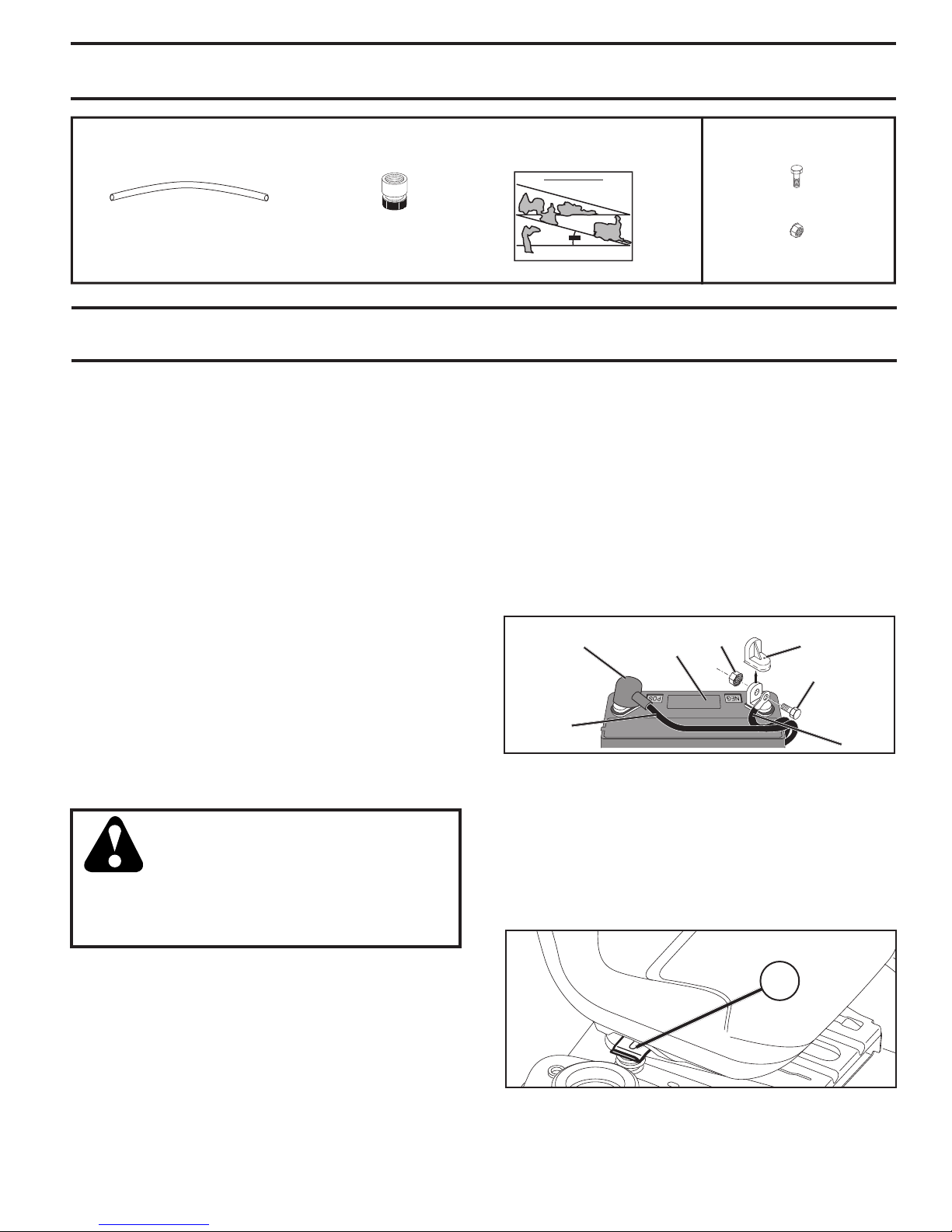
UNASSEMBLED PARTS
Slope Sheet
(1) Quick Connect(1) Oil Drain Tube
Battery
(2) Hex Bolts
(2) Nut Keps
ASSEMBLY
Your new tractor has been assembled at the factory with the exception of those parts left unassembled for shipping purposes.
TOOLS REQUIRED FOR ASSEMBLY
A socket wrench set will make assembly easier. Stan dard
wrench sizes are listed.
(1) 1/2" wrench Tire pressure gauge
(2) 7/16" wrenches Utility knife Pliers
When right or left hand is mentioned in this man ual, it means
when you are in the operating po si tion (seated be hind the
steer ing wheel).
TO REMOVE TRACTOR FROM CARTON
UNPACK CARTON
• Remove all accessible loose parts and parts cartons
from carton.
• Remove end panels and lay side panels flat.
• Check for any additional loose parts or cartons and
remove.
BEFORE REMOVING TRACTOR FROM
SKID
• Determine battery location. Battery location will be
under the seat or the hood.
• Lift seat pan or hood to raised position.
• Remove two terminal caps and discard.
• First connect RED battery cable to positive (+) terminal
with bolt and nut as shown. Tighten securely. Slide
terminal cover over terminal.
• Connect BLACK grounding cable to negative (-)
ter mi nal with remaining bolt and nut. Tighten se cure ly.
• Lower seat pan or hood.
NOTE: For battery installation see “REPLACING BATTERY”
in the Service and Adjustments section in this manual.
TERMINAL
COVER
POSITIVE
(RED)
CABLE
LABEL
02605
Fig. 1
NUT
TERMINAL
CAP
BOLT
NEGATIVE
(BLACK)
CABLE
CONNECT BATTERY (See Fig. 1)
WARNING: Do not short battery ter mi nals
by allowing a wrench or any other object
to contact both terminals at the same
time. Before connecting battery, remove
metal bracelets, wristwatch bands, rings,
etc. Positive terminal must be connected
first to prevent sparking from ac ci den tal
grounding.
NOTE: If this battery is put into service after month and
year indicated on label (label is located between terminals)
charge battery for minimum of one hour at 6-10 amps. (See
“BATTERY” in the Maintenance section of this manual for
charging instructions.)
ADJUST SEAT (See Fig. 2)
• Sit in seat.
• Lift up adjustment lever (A) and slide seat until a comfortable position is reached which allows you to press
clutch/brake pedal all the way down.
• Release lever to lock seat in position.
A
Fig. 2
5
Page 6

ASSEMBLY
NOTE: You may now roll your tractor off the skid. Continue
using the instructions that follow to remove the tractor from
the skid.
WARNING: Before start ing, read, un der stand and fol low all in struc tions in the Op er a tion section of this man u al.
Ensure tractor is in a well-ventilated area. Ensure the area
in front of tractor is clear of other peo ple and objects.
TO ROLL TRACTOR OFF SKID (See Op er a tion
section for location and function of con trols)
• Raise attachment lift lever to its highest po si tion.
• Release parking brake by de press ing clutch/brake
ped al.
• Place freewheel control in "TRANS MIS SION DIS EN-
GAGED" position. (See “TO TRANS PORT” in the
Op er a tion section of this manual.)
• Roll tractor forward off skid.
• Remove banding holding the deflector shield up against
tractor.
Continue with the instructions that follow.
CHECK TIRE PRESSURE
The tires on your tractor were overinflated at the factory
for shipping purposes. Correct tire pressure is important
for best cutting performance.
• Reduce tire pressure to PSI shown on tires.
CHECK DECK LEVELNESS
For best cutting results, mower housing should be properly leveled. See “TO LEVEL MOWER HOUSING” in the
Service and Adjustments section of this manual.
CHECK FOR PROPER POSITION OF ALL
BELTS
See the figures that are shown for replacing motion and
mower blade drive belts in the Service and Adjustments
sec tion of this manual. Verify that the belts are routed
cor rect ly.
CHECK BRAKE SYSTEM
After you learn how to operate your tractor, check to see that
the brake is operating properly. See “TO CHECK BRAKE”
in the Service and Adjustments section of this manual.
✓CHECKLIST
BEFORE YOU OPERATE YOUR NEW TRAC TOR, WE
WISH TO ENSURE THAT YOU RECEIVE THE BEST
PERFORMANCE AND SATISFACTION FROM THIS
QUALITY PRODUCT.
PLEASE REVIEW THE FOLLOWING CHECKLIST:
✓ All assembly instructions have been com plet ed.
✓ No remaining loose parts in carton.
✓ Battery is properly prepared and charged.
✓ Seat is adjusted comfortably and tightened securely.
✓ All tires are properly inflated. (For shipping purposes,
the tires were overinflated at the factory.)
✓ Ensure mower deck is properly leveled side-to-side/
front-to-rear for best cutting results. (Tires must be
properly inflated for leveling.)
✓ Check mower and drive belts. Ensure they are routed
properly around pulleys and inside all belt keepers.
✓ Check wiring. See that all connections are still secure
and wires are properly clamped.
✓ Before driving tractor, ensure free wheel control is in
“TRANSMISSION ENGAGED” position. (See “TO
TRANS PORT” in the Operation section of this man u al.)
WHILE LEARNING HOW TO USE YOUR TRACTOR, PAY EXTRA
ATTENTION TO THE FOLLOWING IMPORTANT ITEMS:
✓ Engine oil is at proper level.
✓ Fuel tank is filled with fresh, clean, regular unleaded
gasoline.
✓ Become familiar with all controls, their location and
functions. Operate them before you start the engine.
✓ Ensure brake system is in safe operating condition.
✓ Ensure Operator Presence System and Reverse
Operation System (ROS) are working properly. (See
the Operation and Maintenance sections in this manual.)
✓ It is important to purge the transmission before op er at ing
your tractor for the first time. Follow proper starting
and transmission purging instructions. (See “TO
START EN GINE” and “PURGE TRANSMISSION” in
the Op er a tion section of this manual.)
6
Page 7
OPERATION
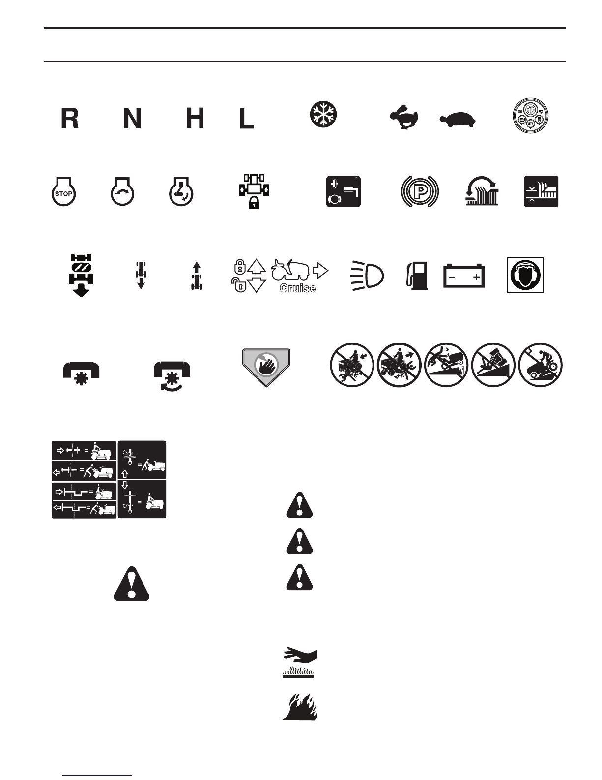
These symbols may appear on your tractor or in literature supplied with the product. Learn and understand their meaning.
ENGINE
OFF
OPERATION
SYSTEM (ROS)
ATTACHMENT
CLUTCH
DISENGAGED
ENGINE
START
REVERSE FORWARD FUEL BATTERYREVERSE
HIGH LOW
ENGINE
ON
ATTACHMENT
CLUTCH
ENGAGED
STARTING POSITION
DIFFERENTIAL
LOCK
DANGER, KEEP
HANDS AND
FEET AWAY
COLD WEATHER
CLUTCH/
BRAKE PEDAL
LIGHTS ONCRUISE CONTROL
KEEP AREA CLEAR SLOPE HAZARDS
FAST
PARKING
BRAKE
(SEE SAFETY RULES SECTION)
SLOWREVERSE NEUTRAL
15
SMARTSWITCH™
MOWER
HEIGHT
PROTECTION
RECOMMENDED
IGNITION
MOWER
LIFT
EAR
15
FREE WHEEL
(Automatic Models only)
Failure to follow instructions
could result in serious injury or
death. The safety alert symbol
is used to identify safety inform-
ation about hazards which can
result in death, serious injury
and/or property damage.
DANGER indicates a hazard which, if not avoided,
will result in death or serious injury.
WARNING indicates a hazard which, if not avoided,
could result in death or serious injury.
CAUTION indicates a hazard which, if not avoided,
might result in minor or moderate injury.
CAUTION when used without the alert symbol,
indicates a situation that could result in damage
to the tractor and/or engine.
HOT SURFACES indicates a hazard which,
if not avoided, could result in death, serious
injury and/or property damage.
FIRE indicates a hazard which, if not avoided,
could result in death, serious injury and/or
property damage.
7
Page 8
OPERATION
KNOW YOUR TRACTOR
READ THIS OPERATOR'S MANUAL AND SAFETY RULES BEFORE OPERATING YOUR TRACTOR
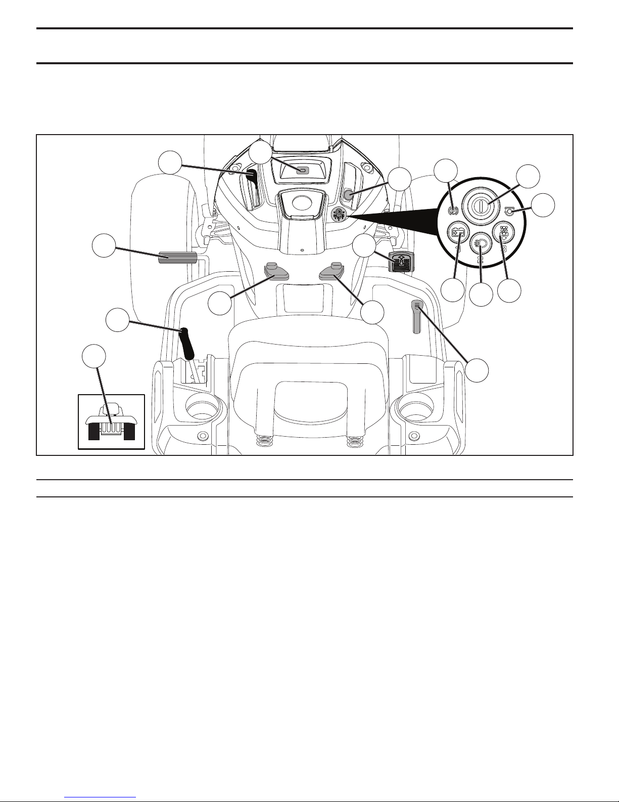
Compare the illustrations with your tractor to familiarize yourself with the locations of various controls and ad just ments.
Save this manual for future reference.
P
D
E
CC
F
EE
B
C
A
M
Our tractors conform to the applicable safety standards of the American National Standards Institute.
(A) ATTACHMENT LIFT LEVER - Used to raise and
lower mower or other attachments mounted to tractor.
(B) BRAKE PEDAL - Used for braking the tractor and
starting the engine.
(C) PARKING BRAKE - Locks clutch/brake pedal into the
brake position.
(CC) PARKING BRAKE SYMBOL - Indicates a starting
fault when the parking brake is disengaged.
(D) THROTTLE CONTROL - Used to control engine speed.
(E) ATTACHMENT CLUTCH SWITCH - Used to engage
mower blades or other attachments mounted to tractor.
(EE) BLADE SWITCH SYMBOL - Indicates a fault when
the attachment clutch switch is engaged.
(F) SMARTSWITCH IGNITION (SSI) BUTTON - Used for
starting/stopping engine and communicating status updates.
(G)* REVERSE OPERATION SYSTEM (ROS) - Allows
operation of mower deck or other powered attachment
while in reverse.
K
I
G
H
J
L
Fig. 3
(H)* HEADLIGHT BUTTON - Turns the headlights on/off.
(I)* BATTERY INDICATOR BUTTON - Used to indicate
low battery voltage or a charging system fault.
(J) CRUISE CONTROL LEVER - Used to set forward
movement of tractor at desired speed without holding the
forward drive pedal.
(K) FORWARD DRIVE PEDAL - Used for forward movement of tractor.
(L) REVERSE DRIVE PEDAL - Used for reverse movement of tractor.
(M) FREEWHEEL CONTROL - Disengages transmission
for pushing or slowly tow ing the trac tor with the engine off.
(P) SERVICE MINDER/HOUR METER - Indicates when
service is required for the engine and mower.
NOTE: G, H, and I are also used as the numerical input buttons
*
for entering the passcode.
8
Page 9
OPERATION
The operation of any tractor can result in foreign objects thrown into the eyes, which can result
in severe eye dam age. Always wear safety glass es or eye shields while operating your tractor
or per form ing any ad just ments or repairs. We rec om mend standard safety glasses or a wide
vision safety mask worn over spectacles.
HOW TO USE YOUR TRAC TOR
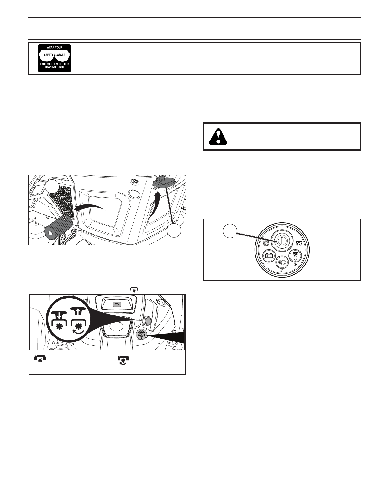
TO SET PARKING BRAKE (See Fig. 4)
Your tractor is equipped with an operator presence sens ing switch. When engine is running, any attempt by the
op er a tor to leave the seat without first setting the parking
brake will shut off the engine.
• Depress brake pedal (B) all the way down and hold.
• Pull parking brake lever (C) up and hold, re lease pres sure from brake pedal (B), then release parking brake
lever. Pedal should re main in brake position. Ensure
parking brake will hold tractor secure.
B
C
Fig. 4
STOPPING (See Fig. 5)
MOWER BLADES -
• To stop mower blades, place attachment clutch control
in the “DIS EN GAGED” position ( ).
( ) ATTACHMENT
CLUTCH SWITCH
“DIS EN GAGED”
GROUND DRIVE -
• To stop ground drive, depress brake pedal into full
“BRAKE” position.
IMPORTANT: FORWARD AND REVERSE DRIVE PEDALS
RETURN TO NEUTRAL POSITION WHEN NOT DEPRESSED.
ENGINE -
• Move throttle control (D) to slow position.
NOTE: Failure to move throttle control to slow position and
allowing engine to idle before stopping may cause engine
to “back fire”.
( ) ATTACHMENT
CLUTCH SWITCH
“ENGAGED”
Fig. 5
• Press SSI button (F) once to stop engine.
NOTE: Under certain conditions when tractor is standing
idle with the engine running, hot en gine exhaust gases
may cause “browning” of grass. To eliminate this possibility,
al ways stop engine when stopping tractor on grass areas.
CAUTION: Always stop tractor com plete ly,
as described above, and set parking brake
before leav ing the op er a tor's position.
MANUALLY LOCKING THE S
(See Fig. 6)
With the engine completely stopped and the SmartSwitch
Ignition (SSI) button (F) blinking green, the SSI button can
be manually locked by pressing buttons "1" and "3" at the
same time for approximately two seconds.
NOTE: The tractor is already locked if asleep or if SSI
button is blinking blue.
MARTSWITCH IGNITION
F
Fig. 6
S
MARTSWITCH SAFETY SYSTEM
Your tractor is equipped with an operator presence sens ing
switch. If the parking brake has not been engaged before
the operator leaves the seat, the engine will shut off. To
continue mowing, the tractor will need to be restarted. See
"TO START ENGINE" in this section of the manual.
TO STOP MOWING
• While seated in operating position, depress brake pedal
and set parking brake.
After setting the parking brake, any attempt by the operator
to leave the seat will stop the mower blades. The engine
will continue to run for approximately five minutes before
shutting off. This allows an operator to momentarily leave
the seat to remove obstacles without having to restart the
tractor.
TO CONTINUE MOWING
• Return to seat.
• Place attachment clutch switch first in "DISENGAGED"
position and then in "ENGAGED" position.
NOTE: Any attempt to place attachment clutch switch in
the "ENGAGED" position without the operator first being
in the seat will immediately shut off engine.
9
Page 10
OPERATION
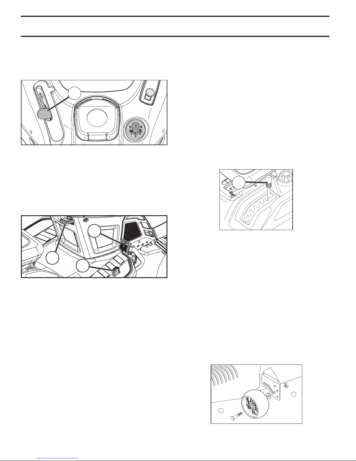
TO USE THROTTLE CONTROL (D) (See Fig.7)
Always operate engine at full speed (fast).
• Operating engine at less than full speed (fast) reduces
the engine's operating efficiency.
• Full speed (fast) of fers the best mower per for mance.
D
Fig. 7
TO MOVE FORWARD AND BACKWARD
(See Fig. 8)
The direction and speed of movement is controlled by the
forward and reverse drive pedals.
• Start tractor and release parking brake.
• Slowly depress forward (K) or reverse (L) drive pedal to
begin movement. Ground speed increases the further
down the pedal is depressed.
TO ADJUST MOWER CUTTING HEIGHT
(See Fig. 9)
The position of the attachment lift lever (A) determines the
cutting height.
• Put attachment lift lever in desired cutting height slot.
The cutting height range is ap prox i mate ly 1 to 4" (25,4 to
101,6 mm). The heights are measured from the ground to
the blade tip with the engine not running. These heights are
approximate and may vary depending upon soil conditions,
height of grass and types of grass being mowed.
• The average lawn should be cut to approximately
2-1/2" (63,5 mm) during the cool season and to over 3"
(76,2 mm) during hot months. For healthier and better
looking lawns, mow often and after moderate growth.
• For best cutting performance, grass over 6" (152,4 mm)
in height should be mowed twice. Make the first cut
relatively high; the second to de sired height.
A
K
J
L
TO USE CRUISE CONTROL (J) (See Fig. 8)
The cruise control feature can be used for forward travel
only.
SYSTEM CHARACTERISTICS
The cruise control should only be used while mowing or
transporting on relatively smooth, straight surfaces. Other
con di tions such as trimming at slow speeds may cause the
cruise control to dis en gage. Do not use the cruise control
on slopes, rough terrian or while trimmimg or turning.
• With forward drive pedal depressed to desired speed,
pull cruise control lever (J) up and hold while lifting
your foot off the pedal, then release the lever.
To disengage the cruise control, depress the brake pedal
or tap on forward drive pedal.
Fig. 9
TO ADJUST GAUGE WHEELS (See Fig. 10)
Gauge wheels are prop er ly ad just ed when they are slight ly
off the ground when mower is at the desired cutting height
in operating position. Gauge wheels then keep the deck
in proper position to help prevent scalping in most terrain
conditions.
NOTE: Adjust gauge wheels with tractor on a flat level
surface.
• Adjust mower to desired cutting height (See “TO AD JUST MOWER CUT TING HEIGHT” in this sec tion of
manual).
• With mower in desired height of cut po si tion, gauge
wheels should be assembled so they are slightly off
the ground. In stall gauge wheel in ap pro pri ate hole.
Tighten se cure ly.
• Repeat for all, installing gauge wheel in same adjustment hole.
9/16”
3/4”
Fig. 10
10
Page 11
OPERATION
TO OPERATE MOWER
Your tractor is equipped with an operator presence sensing switch. While engine is running, any attempt by the
op er a tor to leave the seat without first setting the parking
brake will shut off the engine. You must remain fully and
centrally positioned in the seat to prevent the engine from
hesitating or cutting off when operating your equipment on
rough, rolling terrain or hills.
• Select desired height of cut. (See "TO ADJUST MOWER
CUTTING HEIGHT".)
• Start mower blades by engaging at tach ment clutch
control.
TO STOP MOWER BLADES
Disengage at tach ment clutch con trol.
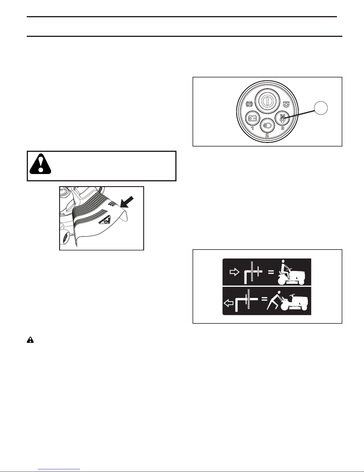
CAUTION: Do not operate the mower without
either the en tire grass catcher, on mowers
so equipped, or the deflector chute in place
(See Fig. 11).
• Release brake pedal and depress reverse drive pedal
to start movement.
• When use of the ROS is no longer needed, press the
ROS button to return to normal operation. The ROS
button should no longer be lit.
G
Fig. 12
TO TRANSPORT (See Fig. 13)
When push ing or tow ing your trac tor, ensure transmission
is disengaged by placing freewheel control in free wheel ing po si tion. Free wheel control is located under the seat.
• Raise attachment lift to highest position with at tach ment
lift control.
• Raise seat and pull freewheel control up and back into
the slot and release so it is held in the disengaged
position.
• Do not push or tow tractor at more than two (2) mph
(3,2 km/h).
• To reengage transmission, reverse above procedure.
Fig. 11
REVERSE OPERATION SYSTEM (ROS)
(See Fig. 12)
Your tractor is equipped with a Reverse Operation System
(ROS). Any attempt by the operator to mow in the reverse
direction without first pressing the ROS button (G) will stop
mower blades. Ensure the transmission is in the neutral
position, move the attachment clutch control to the disengaged position, and then back into the engaged position
before continuing with ROS operation.
WARNING: Backing up with the attachment clutch engaged while mowing is strongly discouraged. Allowing reverse operation with the attachment clutch engaged should
only be done when the operator decides it is necessary
to reposition the machine with the attachment engaged.
Do not mow in reverse unless absolutely necessary.
USING THE REVERSE OPERATION SYSTEM Only use if you are certain no children or other bystanders
will enter the mowing area.
• With engine running, depress brake pedal all the way
down.
• Press ROS button (G) and ensure the ROS button is lit.
• Look down and behind before and while backing.
TRANSMISSION ENGAGED
TRANSMISSION DISENGAGED
Fig. 13
NOTE: To protect hood from damage when transporting
your tractor on a truck or a trailer, ensure hood is closed
and secured to tractor. Use an appropriate means of tying
hood to tractor (rope, cord, etc.).
TOWING CARTS AND OTHER AT TACH MENTS
Tow only the attachments that are recommended by and
comply with specifications of the manufacturer of your tractor. Use common sense when towing. Too heavy of a load,
while on a slope, is dangerous. Tires can lose traction with
the ground and cause you to lose control of your tractor.
11
Page 12
OPERATION
TO OPERATE ON HILLS
CAUTION: Do not drive up or down
hills with slopes greater than 15° and
do not drive across any slope.
• Choose the slowest speed before starting up or down
hills.
• Avoid stopping or changing speed on hills.
• If stopping is absolutely necessary, push brake pedal
quickly to brake position and engage parking brake.
• To restart movement, slowly release parking brake and
brake pedal.
• Slowly depress appropriate drive pedal to slowest set ting.
• Make all turns slowly.
HEADLIGHTS
Headlights can be used without your passcode and with
the engine off.
WITH ENGINE OFF:
• Press headlight button (H) once to turn headlights on
for one minute.
• Press and hold headlight button (H) until headlights
blink twice to turn headlights on for five minutes.
NOTE: If the engine is running and shuts off for any reason,
the headlights will also shut off.
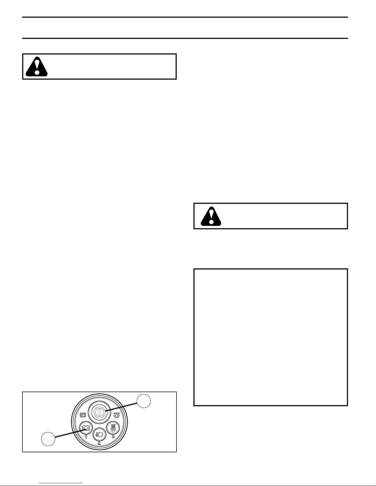
BATTERY INDICATOR BUTTON (See Fig. 14)
The battery indicator button (I) is located on the SmartSwitch
Ignition module and is used to display the status of the
battery. The indicator will only work after the passcode
has been entered and is blinking green.
• Press and hold battery indicator button (I) for three (3)
seconds.
• The SmartSwitch Ignition Button (F) will light up and
indicate the battery status as follows:
RED Charge necessary
RED AND GREEN Charge recommended
GREEN Charge not necessary
• Press the battery indicator button (I) once to stop
viewing the battery status.
NOTE: When the battery is too low and after the first unsuccessful start attempt, the battery indicator button will
blink for two (2) seconds and then stay lit until battery is
charged or until approximately five (5) minutes since last
attempted start.
F
BEFORE STARTING THE ENGINE
CHECK ENGINE OIL LEVEL
The engine in your tractor has been shipped from the factory already filled with sum mer weight oil.
• Check engine oil with tractor on level ground.
• Remove oil fill cap/dipstick and wipe clean, reinsert the
dipstick and screw cap tight, wait for a few seconds,
remove and read oil level. If necessary, add oil until
“FULL” mark on dipstick is reached. Do not overfill.
• For cold weather operation you should change oil for
easier starting. (See “OIL VISCOSITY CHART” in the
Maintenance sec tion of this manual.)
• To change engine oil, see the Maintenance section in
this manual.
ADD GASOLINE
• Fill fuel tank to bottom of filler neck. Do not overfill.
Use fresh, clean, regular gasoline with a minimum of
87 octane. Do not mix oil with gasoline. Purchase fuel
in quantities that can be used within 30 days to ensure
fuel freshness.
CAUTION: Wipe off any spilled oil or
fuel. Do not store, spill or use gasoline
near an open flame.
IMPORTANT: WHEN OPERATING IN TEMPERATURES
BELOW 32°F (0°C), USE FRESH, CLEAN WINTER GRADE
GASOLINE TO HELP ENSURE GOOD COLD WEATHER
STARTING.
CAUTION: Alcohol blended fuels (called gasohol
or using ethanol or methanol) can attract moisture
which leads to sep a ra tion and for ma tion of acids
during storage. Acidic gas can damage the fuel
system of an engine while in storage. To avoid
engine problems, the fuel system should be emptied
before stor age of 30 days or longer. Drain the gas
tank, start the engine and let it run until the fuel
lines and carburetor are empty. Use fresh fuel next
season. See Storage In struc tions for additional
information. Never use engine or carburetor cleaner
products in the fuel tank or permanent damage may
occur. Fuel stabilizer is an acceptable alternative
in minimizing the formation of fuel gum deposits
during stor age. Add stabilizer to gasoline in fuel
tank or storage container. Always follow the mix
ratio found on stabilizer container. Run engine at
least 10 minutes after adding stabilizer to allow the
stabilizer to reach the carburetor. Do not empty
the gas tank and carburetor if using fuel stabilizer.
I
Fig. 14
12
Page 13
OPERATION
RESETTING IGNITION SYSTEM PASSCODE
(See Fig. 15)
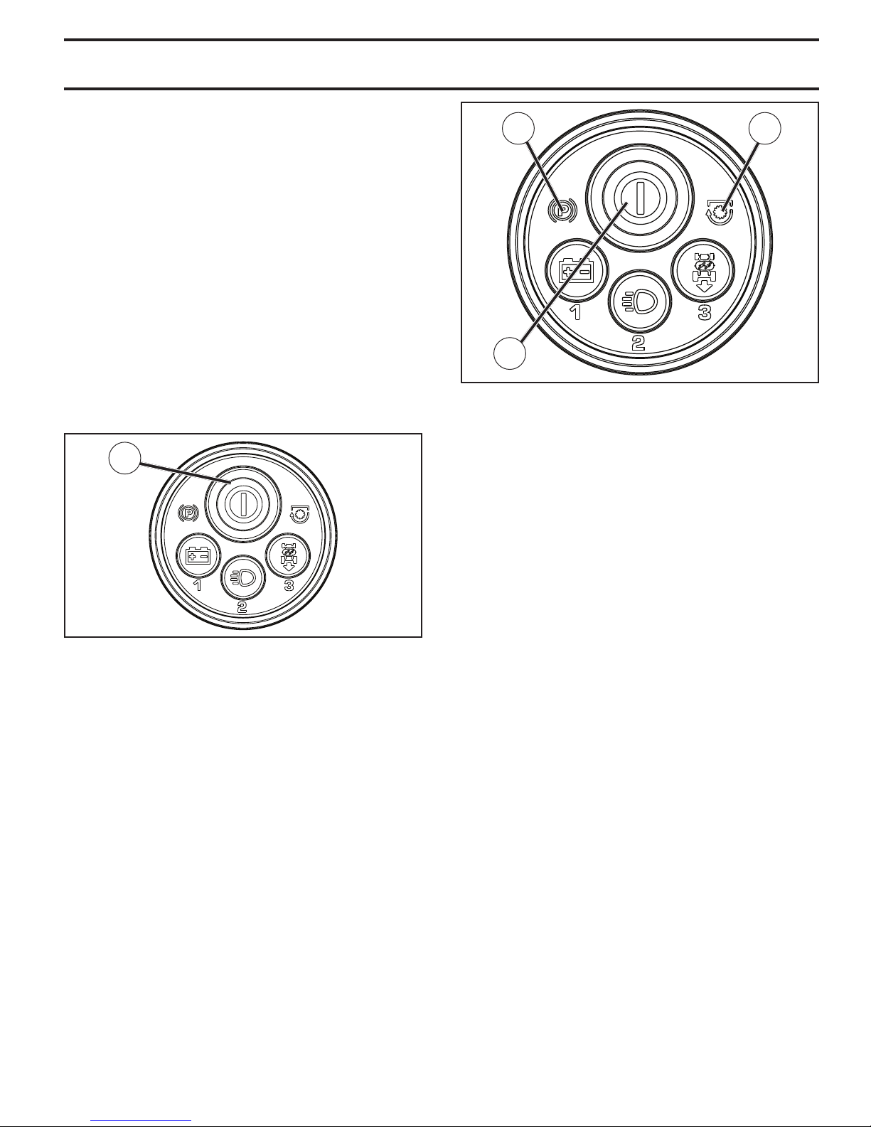
The SmartSwitch Ignition is preset at the factory with the
default code "321". To reset or change the passcode, the
operator does not have to be seated on the tractor.
1. Press the SmartSwitch Ignition (SSI) button (F) once (or
sit on the seat). Ensure the indicator is blinking blue.
2. Press and hold the (1) and (3) buttons simultaneously
for approximately three (3) seconds until the SSI button
changes to solid blue.
3. Using the numbered buttons, enter the desired passcode. The passcode may be anywhere from one to
five digits in length.
4. After the desired passcode has been entered, press
the SSI button (F) once.
NOTE: When the indicator flashes green, the passcode has
been accepted. If the indicator blinks red, the passcode has
not been accepted. Wait until the indicator returns to blinking blue and repeat this procedure starting from step two.
F
CC EE
F
Fig. 16
PRE-START
• Ensure freewheel control is in the transmission en gaged
position.
• Ensure transmission is in the neutral position
• Move attachment clutch control to the “DISENGAGED”
position.
• Sit on seat in operating position, depress brake pedal
and set parking brake.
Fig. 15
TO START ENGINE
NOTE: The default passcode "321" is preset at the factory
and should be changed prior to first use. (See "RESETTING IGNITION SYSTEM PASSCODE" in this section of
the manual.)
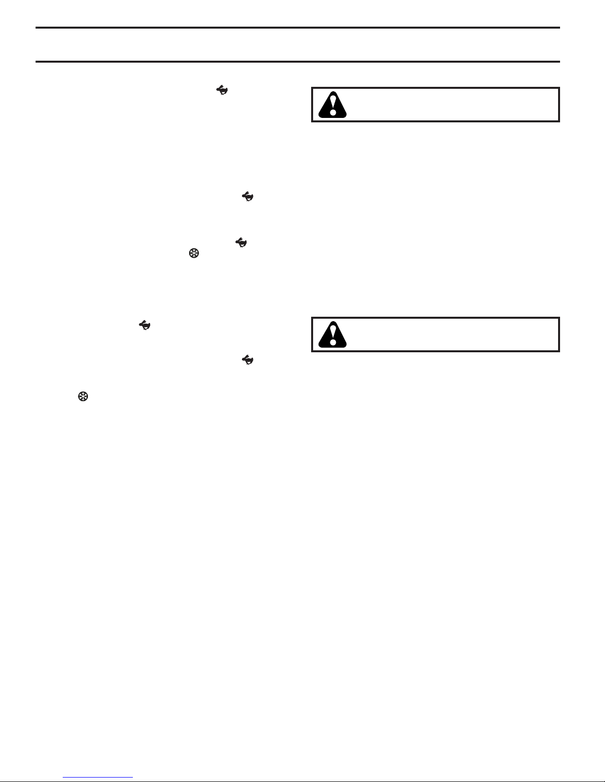
SMARTSWITCH WARNING LIGHTS (See Fig. 16)
The SmartSwitch Ignition is programmed with warning lights
to indicate when any part of the safety system is not being
followed. The engine will not start until all the following
ignition system faults are resolved:
• The park brake symbol (CC) will be lit if the parking
brake has not been engaged during a start attempt.
• The blade switch symbol (EE) will blink if the attachment
clutch control is not in the "DISENGAGED" position
during a start attempt.
MARTSWITCH IGNITION UNLOCK
S
1. Press the SmartSwitch Ignition (SSI) button (F) once (or
sit on the seat). Ensure the indicator is blinking blue.
2. Enter passcode and press the SSI button. If passcode
is not accepted, the SSI button will blink red. Wait until
the SSI button returns to blinking blue before attempting
to re-enter passcode. Once accepted, the SSI button
will flash green.
3. Ensure that the SmartSwitch Safety System warning
lights are not showing any faults present. If any warning
lights do indicate faults present, resolve those faults
before continuing with STARTING.
STARTING
The Briggs & Stratton Endurance engine equipped with
your tractor features a Ready-Start automatic choke system
to provide simplified starting in normal conditions. Please
read the following starting instruction carefully.
NOTE: For the first time starting after your tractor has sat
for an extended period of time, or after running out of gas,
the engine may require an extended start attempt to reprime
the fuel system. For an extended start, press and hold
SSI button for three seconds before releasing. This will
prompt the engine to attempt starting for up to ten seconds
(instead of the normal five seconds), allowing time for fuel
to be pulled into the engine.
13
Page 14
OPERATION
NORMAL STARTING (32°F/0°C and above)
1. Move throttle control to fast position ( ).
2. Perform procedures outlined in "SMARTSWITCH IGNITION
UNLOCK" as previously described.
3. While the SSI button (F) is flashing green, press and
release the SSI button once more to start the engine.
• Once engine starts, the attachments and ground
drive can now be used. If the engine does not accept
the load, restart the engine and allow it to warm up
for one minute.
• Leave throttle control in fast position ( ) while
mowing.
COLD WEATHER STARTING (32°F/0°C and below)
1. Move throttle control beyond fast position ( ) into the
cold weather starting position ( ).
2. Perform procedures outlined in "S
UNLOCK" as previously described.
3. While the SSI button is flashing green, press the SSI
button once more to start the engine.
• Once engine starts, move the throttle control back to
the fast position ( ) to warm-up. The time required
for warm-up will vary from a few seconds to a minute
depending upon conditions and temperature.
• Leave throttle control in fast position (
mowing.
NOTE: Failure to move throttle from cold weather starting
position (
spark plug fouling.
AUTOMATIC TRANSMISSION WARM UP
• Before driving the unit in cold weather, the trans mis sion
should be warmed up as follows:
• Ensure the tractor is on level ground.
• Release the parking brake and let the brake slowly
• Allow one minute for transmission to warm up. This
• The attachments can also be used during the engine
warm-up period after the transmission has been warmed
up.
) will result in poor engine performance and
return to operating position.
can be done during the engine warm up period.
MARTSWITCH IGNITION
) while
PURGE TRANSMISSION
CAUTION: Never engage or disengage freewheel lever while the engine is run ning.
To ensure proper operation and performance, it is rec om mend ed that the transmission be purged before operating
tractor for the first time. This procedure will remove any
trapped air inside the transmission which may have de vel oped during shipping of your tractor.
IMPORTANT: SHOULD YOUR TRANSMISSION RE QUIRE
REMOVAL FOR SERVICE OR REPLACEMENT, IT SHOULD
BE PURGED AFTER REINSTALLATION BEFORE OPERATING
THE TRACTOR.
1. Place tractor safely on a level surface - that is clear
and open - with engine off and parking brake set.
2. Disengage transmission by placing freewheel control
in disengaged position. (See “TO TRANSPORT” in
this section of manual.)
3. Sitting in the tractor seat, start engine. After the engine is running, move throttle control to slow position.
Dis en gage parking brake
CAUTION: At any time, during step 4, there
may be movement of the drive wheels.
4. Depress forward drive pedal to full forward position,
hold for five (5) seconds and release pedal. Depress
reverse drive pedal to full reverse position, hold for five
(5) seconds and release pedal. Repeat this procedure
three (3) times.
5. Shut- off engine and set parking brake.
6. Engage transmission by placing freewheel control
in engaged position. (See “TO TRANSPORT” in this
sec tion of manual.)
7. Sitting in the tractor seat, start engine. After the engine
is running, move throttle control to half (1/2) speed.
Disengage parking brake.
8. Drive tractor forward for approximately 5 feet (1,5 m)
then backwards for 5 feet (1,5 m). Repeat this driving
procedure three times.
Your transmission is now purged and now ready for normal
op er a tion.
SERVICE MINDER/HOURMETER
Service reminder shows the total number of hours the
engine has run and indicates when the engine or mower
needs servicing. After every 50 hours of operation the oil
can icon will stay on for 2 hours. To service engine and
mower, see the Maintenance section of this manual.
NOTE: The service minder runs when either the engine is
running or the SmartSwitch is active (unlocked).
14
Page 15
OPERATION
MOWING TIPS
• DO NOT use tire chains when the mower hous ing is
attached to tractor.
• Mower should be properly leveled for best mowing
performance. See “TO LEVEL MOWER HOUSING”
in the Service and Adjustments section of this manual.
• The left hand side of mower should be used for trim ming.
• Drive so that clippings are discharged onto the area
that has been cut. Have the cut area to the right of
the tractor. This will result in a more even dis tri bu tion
of clippings and more uniform cutting.
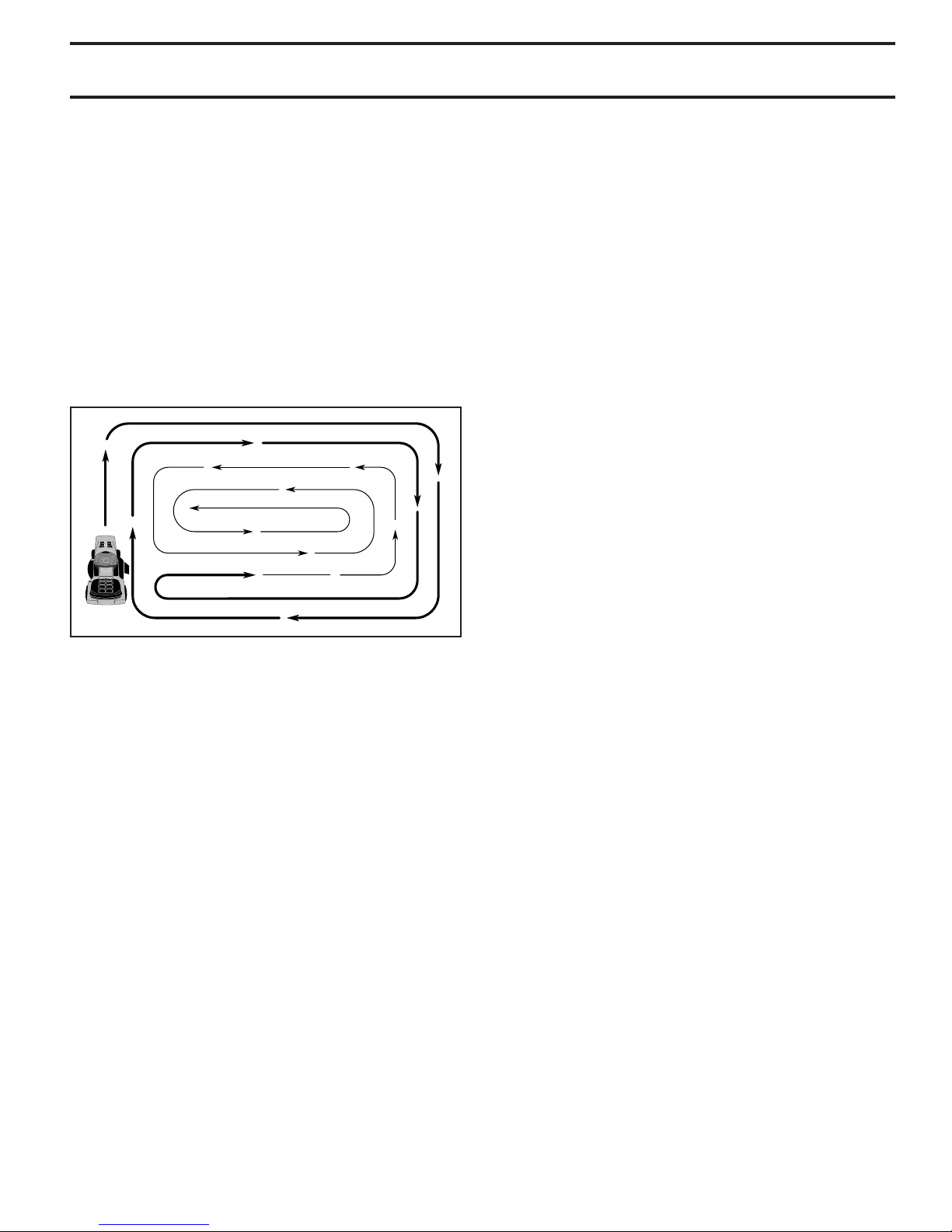
• When mowing large areas, start by turning to the right
so that clippings will discharge away from shrubs,
fences, driveways, etc. After one or two rounds, mow
in the opposite direction making left hand turns until
finished (See Fig. 17).
Fig. 17
• If grass is extremely tall, it should be mowed twice to
reduce load and possible fire hazard from dried clip pings. Make first cut relatively high; the second to the
desired height.
• Do not mow grass when it is wet. Wet grass will plug
mower and leave undesirable clumps. Allow grass to
dry before mowing.
• Always operate engine at full throttle when mow-
ing to ensure better mowing performance and proper
dis charge of material. Regulate ground speed by
se lect ing a low enough gear to give the mower cut ting
per for mance as well as the quality of cut desired.
• When operating attachments, select a ground speed
that will suit the terrain and give best performance of
the at tach ment being used.
15
Page 16
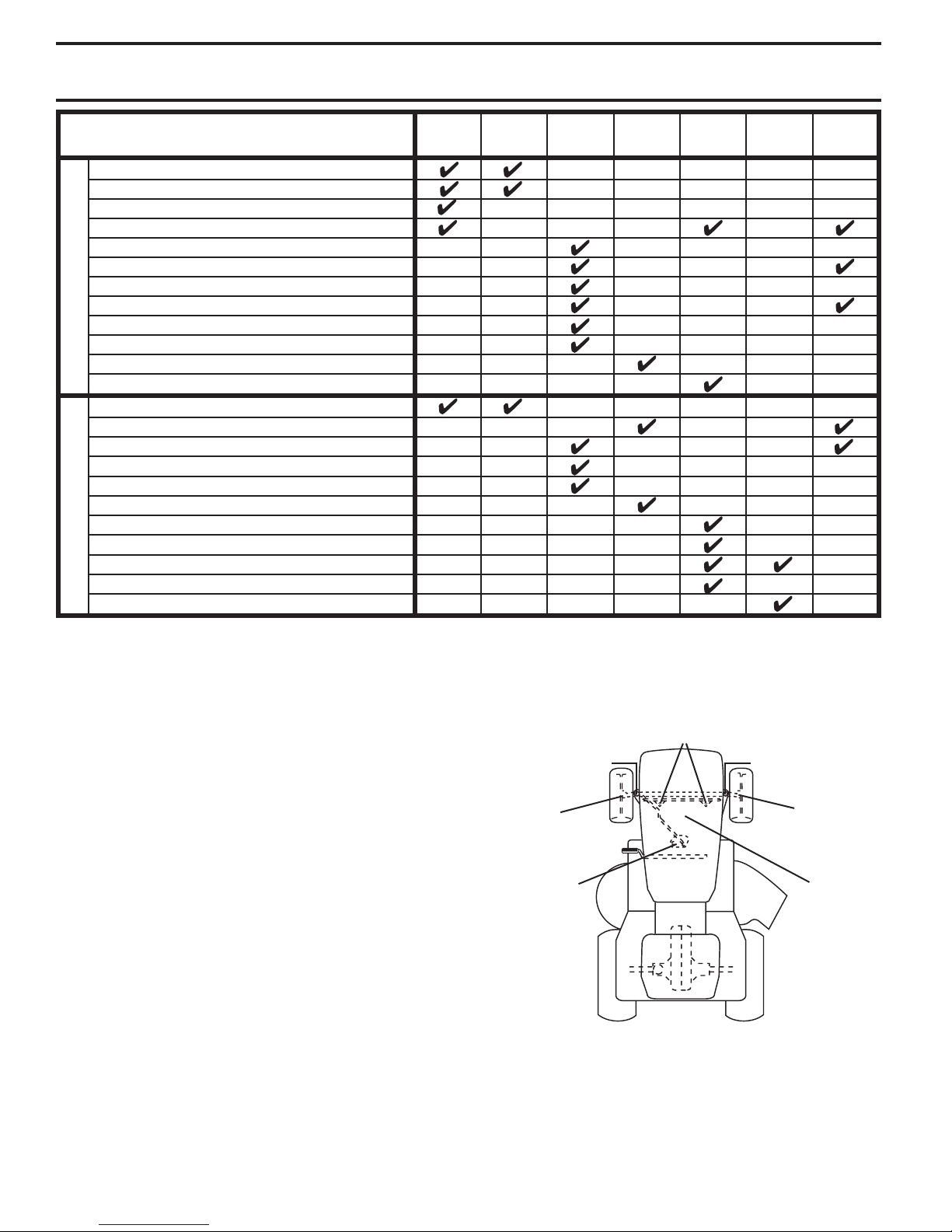
MAINTENANCE
MAINTENANCE SCHEDULE
Check Brake Operation
Check Tire Pressure
Check Operator Presence and ROS Systems
T
Check for Loose Fasteners
R
Check/Replace Mower Blades
A
Lubrication Chart
C
T
Check Battery Level
O
Clean Battery and Terminals
R
Clean Debris off Steering Plate
Check Transaxle Cooling
Check Mower Levelness
Check V-Belts
Check Engine Oil Level
Change Engine Oil (models with oil filter)
Change Engine Oil (models without oil filter)
E
Clean Air Filter
N
Clean Air Screen
G
Inspect Muffler/Spark Arrester
I
Replace Oil Filter (If equipped)
N
Clean Engine Cooling Fins
E
Replace Spark Plug
Replace Air Filter Paper Cartridge
Replace Fuel Filter
1 - Change more often when operating under a heavy load or in high ambient temperatures
2 - Service more often when operating in dirty or dusty conditions.
BEFORE
EACH
USE
EVERY
8
HOURS
3 - Replace blades more often when mowing in sandy soil.
4 - Not required if equipped with maintenance-free battery.
EVERY
HOURS
25
EVERY
50
HOURS
3
4
5
1,2
2
2
EVERY
100
HOURS
1,2
5 - See Cleaning in Maintenance Section.
EVERY
SEASON
,
21
2
2
BEFORE
STORAGE
GENERAL RECOMMENDATIONS
The warranty on this tractor does not cover items that have
been subjected to operator abuse or negligence. To receive
full value from the warranty, operator must main tain tractor
as instructed in this manual.
Some adjustments will need to be made periodically to
properly maintain your tractor.
At least once a season, check to see if you should make
any of the adjustments described in the Service and
Adjustments section of this manual.
• At least once a year you should replace the spark plug,
clean or replace air filter, and check blades and belts
for wear. A new spark plug and clean air filter assure
proper air-fuel mixture and help your engine run better
and last longer.
BEFORE EACH USE
• Check engine oil level.
• Check brake operation.
• Check tire pressure.
• Check operator presence and ROS systems for proper
operation.
• Check for loose fasteners.
LUBRICATION CHART
STEERING PIVOT BOLTS
➀
SPINDLE ZERK
➀
FRONT
➀
WHEEL
BEARING
ZERK
STEERING
➀
SECTOR
GEAR
TEETH
General Purpose Grease
➀
Refer to Maintenance “ENGINE” Section
➁
SPINDLE ZERK
➀
FRONT
➀
➁
IMPORTANT: DO NOT OIL OR GREASE THE PIVOT POINTS
WHICH HAVE SPECIAL NYLON BEARINGS. VISCOUS
LU BRI CANTS WILL ATTRACT DUST AND DIRT THAT WILL
SHORT EN THE LIFE OF THE SELF-LU BRI CAT ING BEARINGS.
IF YOU FEEL THEY MUST BE LU BRI CAT ED, USE ONLY A
DRY, POW DERED GRAPHITE TYPE LU BRI CANT SPARINGLY.
16
WHEEL
BEARING
ZERK
ENGINE
Page 17

MAINTENANCE
TRACTOR
Always observe safety rules when per form ing any
main te nance.
BRAKE OPERATION
If tractor requires more than five (5) feet (1,5 m) to stop at
highest speed in high est gear on a level, dry concrete or
paved surface, then brake must be checked and ad just ed.
(See “TO CHECK BRAKE” in the Ser vice and Ad just ments
section of this manual.)
TIRES
• Maintain proper air pressure in all tires. (See the sides
of tires for proper PSI.)
• Keep tires free of gasoline, oil, or insect control
chemi cals which can harm rubber.
• Avoid stumps, stones, deep ruts, sharp objects and
other hazards that may cause tire damage.
NOTE: To seal tire punctures and pre vent flat tires due
to slow leaks, tire sealant may be purchased from your
local parts dealer. Tire sealant also pre vents tire dry rot
and corrosion.
OPERATOR PRESENCE SYS TEM AND REVERSE
OPERATION SYSTEM (ROS) (See Fig. 18)
Ensure operator presence and reverse operation sys tems
are work ing properly. If your tractor does not function as
described, repair the problem immediately.
• The engine should not start unless the parking brake
is engaged, and the attachment clutch con trol is in the
dis en gaged position.
CHECK OPERATOR PRESENCE SYSTEM
• While the engine is running, any attempt by the op er a tor
to leave the seat without first setting the parking brake
should shut off the engine.
• With the engine running, the parking brake engaged,
and the at tach ment clutch engaged, any attempt by the
operator to leave the seat should shut off the attachment
clutch.
• The attachment clutch should never operate unless
the operator is in the seat.
CHECK REVERSE OPERATION (ROS) SYSTEM
• With the engine running, the SmartSwitch Ignition
(SSI) button (F) solid green, and the attachment clutch
engaged any attempt by the operator to shift in reverse
will stop the mower blades.
• With the engine running, the SmartSwitch Ignition (S SI)
button (F) solid green, and the ROS button (G) lit, any
attempt by the operator to shift in reverse should NOT
stop the mower blades.
BATTERY
Your tractor has a battery charging system which is suf fi cient
for normal use. However, periodic charging of the battery
with an automotive charger will extend its life.
• Keep battery and terminals clean.
• Keep battery bolts tight.
• Keep small vent holes open.
• Recharge at 6-10 amperes for 1 hour.
NOTE: The original equipment battery on your tractor is
maintenance free. Do not attempt to open or remove caps
or covers. Adding or checking level of electrolyte is not
necessary.
TO CLEAN BATTERY AND TERMINALS
Corrosion and dirt on the battery and terminals can cause
the battery to “leak” power.
• Remove terminal guard.
• Disconnect BLACK battery cable first then RED bat tery
cable and remove battery from tractor.
• Rinse the battery with plain water and dry.
• Clean terminals and battery cable ends with wire brush
until bright.
• Coat terminals with grease or petroleum jelly.
• Reinstall battery. (See “REPLACING BATTERY" in the
Service and Adjustments section of this manual.)
V-BELTS
Check V-belts for deterioration and wear after 100 hours
of operation and replace if necessary. The belts are not
ad just able. Re place belts if they begin to slip from wear.
TRANSAXLE MAINTENANCE
The transmission fan and cooling fins should be kept clean
to ensure proper cooling.
Do not attempt to clean fan or transmission while engine
is running or while the transmission is hot. To prevent pos si ble damage to seals, do not use high pressure water or
steam to clean transmission.
• Inspect cooling fan to be sure fan blades are intact and
clean.
• Inspect cooling fins for dirt, grass clippings and other
materials. To prevent damage to seals, do not use compressed air or high pressure sprayer to clean cool ing fins.
TRANSAXLE PUMP FLUID
The transaxle was sealed at the factory and fluid main te nance is not required for the life of the transaxle. Should
the transaxle ever leak or require servicing, contact your
near est au tho rized ser vice center/department.
Fig. 18
F
G
17
Page 18
MAINTENANCE
BLADE CARE
For best results mower blades must be kept sharp. Re place
bent or damaged blades.
CAUTION: Use only a replacement blade approved by the manufacturer of your tractor.
Using a blade not approved by the manufacturer of your tractor is hazardous, could
damage your tractor, and void your warranty.
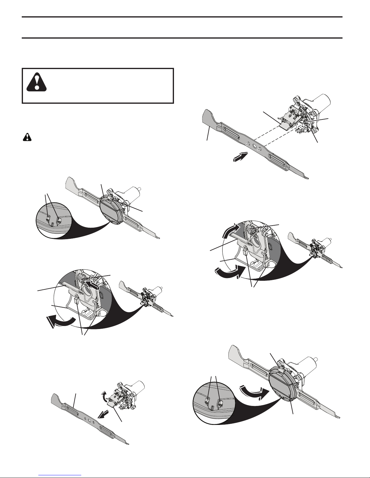
BLADE REPLACEMENT (See Figs. 19 - 24)
• Raise mower to highest position to allow access to
blades.
CAUTION: When handling the blade, protect your hands
with gloves and/or wrap blade with heavy cloth.
TO REMOVE BLADE
• Squeeze tabs inward to release cap. Remove by lifting
cap from hinge and set aside. (See Fig. 19.)
CAP
TABS
HINGE
TO INSTALL BLADE
• Clean area under top plate, the bottom of the mandrel
assembly, and around bosses thoroughly to remove
any dirt or debris.
• Align bosses and insert blade. (See Fig. 22.)
NOTE: Magnets should hold blade in place.
TOP PLATE
BOSS
BLADE
MANDREL
ASSEMBLY
Fig. 22
• Close the top plate over the blade and hook the wireform over the standoffs.
• Push pivot closed until secured by the thumb lock. (See
Fig. 23.)
Fig. 19
• Slide thumb lock and release pivot to allow wire-form
to swing free from standoffs. (See Fig. 20.)
THUMB LOCK
PIVOT
WIRE-FORM
STANDOFFS
Fig. 20
• Open the top plate and remove blade. (See Fig. 21.)
NOTE: Blade is held in place by magnets to prevent free
release.
BLADE
THUMB LOCK
PIVOT
WIRE-FORM
STANDOFFS
Fig. 23
• Reinstall cap. Hook cap onto hinge and rotate onto
tabs. Press cap firmly into place, ensuring both tabs
lock into cap. (See Fig. 24.)
NOTE: Replace cap if worn or cracked.
HINGE
TABS
TOP PLATE
Fig. 21
CAP
Fig. 24
18
Page 19
MAINTENANCE
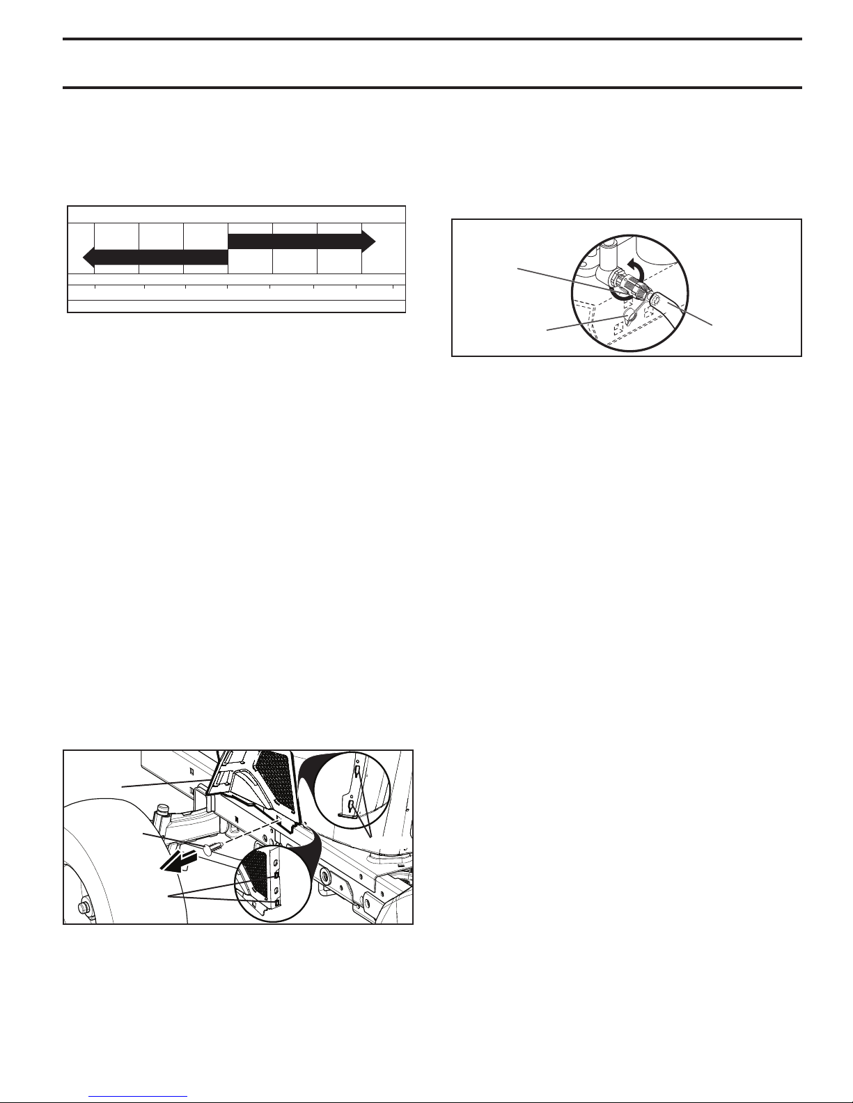
TEMPERATURE RANGE ANTICIPATED BEFORE NEXT OIL CHANGE
SAE VISCOSITY GRADES
-20 0 30 40
80
100
-30
-20 0
20 30 40
F
C
32
-10
10
60
5W-30
SAE 30
ENGINE
LUBRICATION
Only use high quality detergent oil rated with API service
classification SG-SL. Select the oil’s SAE viscosity grade
according to your expected operating temperature.
Fig. 25
NOTE: Although multi-viscosity oils (5W30, 10W30 etc.)
improve starting in cold weather, they will result in increased
oil consumption when used above 32°F/0°C Check your
engine oil level more frequently to avoid possible engine
damage from running low on oil.
Change the oil after every 50 hours of operation or at least
once a year if the tractor is not used for 50 hours in one year.
Check the crankcase oil level before starting the engine
and after each eight (8) hours of operation. Tighten oil fill
cap/dipstick securely each time you check the oil level.
TO CHANGE ENGINE OIL (See Fig. 25 - 27)
Determine temperature range expected before oil change.
All oil must meet API service classification SG-SL.
• Ensure tractor is on level surface.
• Oil will drain more freely when warm.
• Catch oil in a suitable container.
LOWER DASH COVER REMOVAL
• Raise hood.
• Remove fastener from lower dash cover.
CAUTION: Remove lower dash cover carefully to ensure
cover tabs are not broken.
• Slide lower dash cover up to release cover tabs from
tapered slots in lower dash and remove.
LOWER
DASH
COVER
FASTENER
SLOTS
• Remove oil fill cap/dipstick. Be careful not to allow dirt
to enter the engine when changing oil.
• Remove yellow cap from end of drain valve and install
the drain tube onto the fitting.
• Unlock drain valve by pushing inward and turning
coun ter clock wise.
• To open, pull out on the drain valve.
OIL DRAIN VALVE
CLOSED
AND
LOCKED
POSITION
YEL LOW CAP
02463
DRAIN
TUBE
Fig. 27
• After oil has drained completely, close and lock the
drain valve by pushing inward and turning clockwise
until the pin is in the locked position as shown.
• Remove the drain tube and replace the cap onto to the
bottom fitting of the drain valve.
• Refill engine with oil through oil fill dipstick tube. Pour
slowly. Do not overfill. For approximate capacity see
“PRODUCT SPECIFICATIONS” section of this man u al.
• Use gauge on oil fill cap/dipstick for checking level.
Ensure dipstick cap is tightened securely for accurate
reading. Keep oil at “FULL” line on dipstick. Tighten
cap onto the tube securely when finished.
ENGINE OIL FILTER
Replace the engine oil filter every season or every other
oil change if the tractor is used more than 100 hours in
one year.
NOTE: If needed, remove lower dash covers using steps
from "Lower dash cover removal" section of this manual.
AIR FILTER
Your engine will not run properly using a dirty air filter. Service air cleaner more often under dusty conditions.
CLEAN AIR SCREEN
The air screen is over the air intake blower located on top
of engine. The air screen must be kept free of dirt and
chaff to prevent engine dam age from overheating. Clean
with a wire brush or compressed air to re move dirt and
stubborn dried gum fibers.
TABS
Fig. 26
19
Page 20
MAINTENANCE
ENGINE COOLING SYSTEM
To ensure proper cooling, make sure the grass screen,
cooling fins, and other external surfaces of the engine are
kept clean at all times.
Every 100 hours of operation (more often under extremely
dusty, dirty conditions), remove the blower housing and
other cooling shrouds. Clean the cooling fins and external
surfaces as necessary. Ensure the cooling shrouds are
reinstalled.
NOTE: Operating the engine with a blocked grass screen,
dirty or plugged cooling fins, and/or cooling shrouds re moved
will cause engine damage due to overheating.
MUFFLER
Inspect and replace corroded muffler and spark arrester (if
equipped) as it could create a fire hazard and/or damage.
SPARK PLUGS
Replace spark plugs at the beginning of each mowing
season or after every 100 hours of operation, whichever
occurs first. Spark plug type and gap setting are shown in
“PROD UCT SPECIFICATIONS” section of this manual.
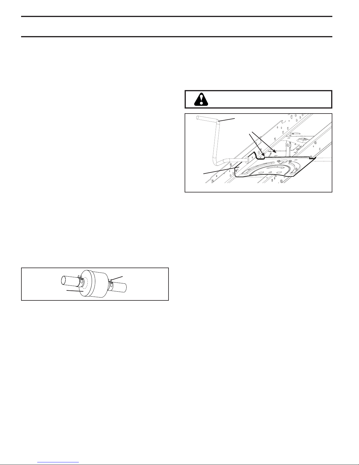
IN-LINE FUEL FILTER (See Fig. 28)
The fuel filter should be replaced once each season. If fuel
filter becomes clogged, ob struct ing fuel flow to car bu re tor,
re place ment is re quired.
• With engine cool, remove filter and plug fuel line sec tions.
• Place new fuel filter in position in fuel line with arrow
pointing towards carburetor.
• Be sure there are no fuel line leaks and clamps are
properly positioned.
• Immediately wipe up any spilled gasoline.
CLAMP
CLEANING
• Clean engine, battery, seat, finish, etc. of all foreign
matter.
• Clean debris from steering plate. Debris can restrict
clutch/brake pedal shaft movement, causing belt slip
and loss of drive. See Fig. 29.
CAUTION: Avoid all pinch points and
movable parts.
CLUTCH/BRAKE PEDAL
CLEAN
TOP SIDE
STEERING
PLATE
STEERING SYSTEM, DASH, FENDER AND MOWER NOT SHOWN
Fig. 29
• Keep finished surfaces and wheels free of all gasoline,
oil, etc.
• Protect painted surfaces with automotive type wax.
Except for the washout port (if equipped), we do not
recommend using a garden hose or pressure washer to
clean the outside of your tractor unless the engine and
transmission are covered to keep water out. Water in
engine or transmission will shorten the useful life of your
tractor. Use compressed air or a leaf blower to remove
grass, leaves and trash from outside tractor and mower.
FUEL FILTER
Fig. 28
20
Page 21
MAINTENANCE
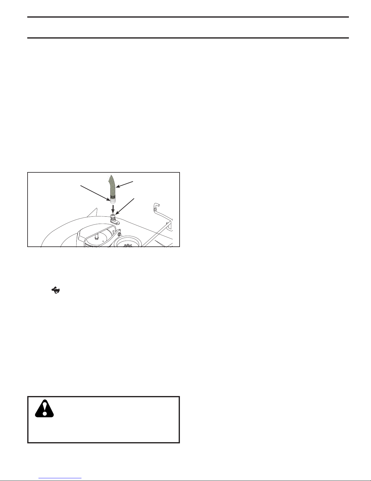
DECK WASHOUT PORT (See Fig. 30)
Your tractor’s deck is equipped with a washout port on
its surface as part of its deck wash system. It should be
utilized after each use.
• Drive the tractor to a level, clear spot on your lawn, near
enough to a water spigot for your garden hose to reach.
IMPORTANT: Make certain the tractor’s discharge chute
is directed AWAY from your house, garage, parked cars,
etc. Remove bagger chute or mulch cover if attached.
• Make sure the attachment clutch control is in the
“DISENGAGED” position, set the parking brake, and
stop the engine.
• Ensure your garden hose is fitted with a standard 12mm
female hose connector (at the opposite end from the
tap connection).
• Pull back the lock collar of the hose connector and push
the connector onto the deck washout port at the left end
of the mower deck. Release the lock collar to lock the
connector on the nozzle.
HOSE CONNECTOR
(12mm FEMALE)
Fig. 30
IMPORTANT: Tug hose ensuring connection is secure.
• Turn the water on.
• While sitting in the operator’s position on the tractor,
re-start the engine and place the throttle lever in the
Fast "
IMPORTANT: Recheck the area making certain the area
is clear.
• Move the tractor’s attachment clutch control to the
“ENGAGED” position. Remain in the operator’s position
with the cutting deck engaged until the deck is cleaned.
• Move the tractor’s attachment clutch control to the
“DISENGAGED” position. Turn the ignition key to the
STOP position to turn the tractor’s engine off. Turn the
water off.
• Pull back the lock collar of the hose connector to
disconnect the connector from the nozzle washout port.
• Move the tractor to a dry area, preferably a concrete or
paved area. Place the attachment clutch control in the
“ENGAGED” position to remove excess water and to
help dry before putting the tractor away.
" position.
HOSE
WASHOUT
PORT
WARNING: A broken or missing washout
fitting could expose you or others to
thrown objects from contact with the blade.
• Replace broken or missing washout fitting
immediately, prior to using mower again.
• Plug any holes in mower with bolts and locknuts.
21
Page 22
SERVICE AND ADJUSTMENTS
WARNING: TO AVOID SERIOUS INJURY, BEFORE PERFORMING ANY SER VICE OR AD JUST MENTS:
• Depress brake pedal fully and set parking brake.
• Place attachment clutch in “DISENGAGED” position.
• Shut engine off and lock the SmartSwitch Ignition.
• Ensure the blades and all moving parts have completely stopped.
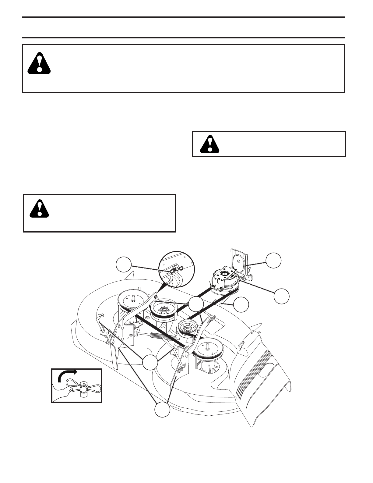
TO REMOVE MOWER (See Fig. 31)
• Place attachment clutch in “DIS EN GAGED” position.
• Lower attachment lift lever to its lowest position.
• Remove mower belt from electric clutch pulley (M).
• Disconnect front link (E) from mower - remove retainer
spring and washer.
• Go to either side of mower and disconnect mower
suspension arm (A) from chassis and rear lift link (C)
from rear mower bracket (D) - remove retainer springs
and washers.
• Go to other side of mower and disconnect the suspension arm and rear lift link.
CAUTION: After rear lift links are disconnected, the attachment lift lever
will be spring loaded. Have a tight grip
on lift lever when changing position of
the lever.
• Slide mower out from under right side of tractor.
B
TO INSTALL MOWER (See Figs. 31 - 36)
Ensure tractor is on level surface and engage park ing brake.
• Lower attachment lift lever to its lowest position.
CAUTION: Lift lever is spring loaded.
Have a tight grip on lift lever, lower it
slowly and engage in lowest position.
NOTE: Ensure mower side suspension arms (A) are point-
ing forward before sliding mower under tractor.
• Slide mower under tractor until it is centered under
tractor.
F
C
D
Fig. 31
22
A
M
E
Page 23
SERVICE AND ADJUSTMENTS
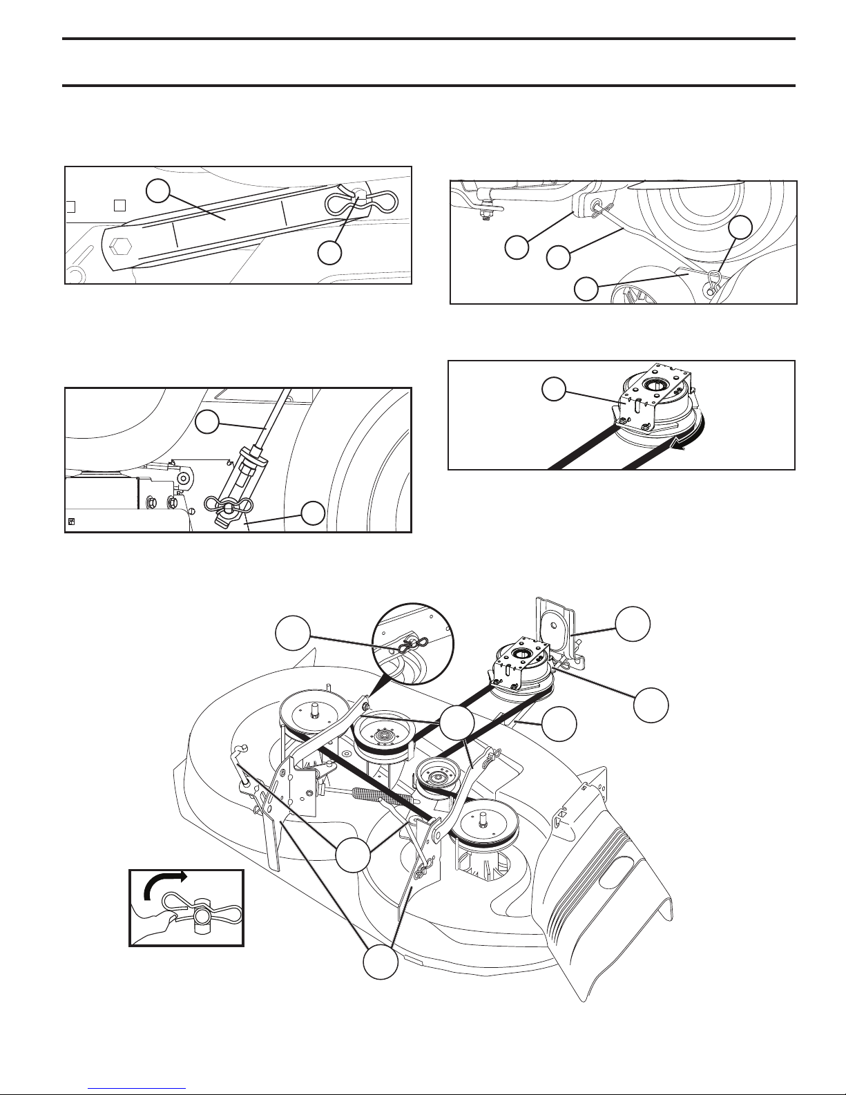
• ATTACH MOWER SIDE SUSPENSION ARMS (A) TO
CHASSIS - Position hole in arm over pin (B) on outside
of tractor chassis and secure with retainer spring.
• Repeat on opposite side of tractor.
A
B
Fig. 32
• ATTACH REAR LIFT LINKS (C) - Lift rear corner of
mower and position slot in link assembly over pin on
rear mower bracket (D) and secure with washer and
retainer spring.
C
• ATTACH FRONT LINK (E) - Work from left side of tractor. Insert rod end of link assembly through front hole
in tractor front suspension bracket (F).
• Insert end of link (E) into hole in front mower bracket
(H) and secure with washer and retainer spring (J).
J
F
E
H
Fig. 34
• Install belt onto electric clutch pulley (M).
M
Fig. 35
Fig. 33
B
D
IMPORTANT: CHECK BELT FOR PROPER ROUTING
IN ALL MOWER PULLEY GROOVES.
• Raise attachment lift lever to highest position.
• If necessary, adjust gauge wheels before op er at ing
mower as shown in the Operation section of this manual.
F
M
A
E
C
D
Fig. 36
23
Page 24
SERVICE AND ADJUSTMENTS
TO LEVEL MOWER
Make sure tires are properly inflated to the PSI shown on
tires. If tires are over or under inflated, it may affect the
appearance of your lawn and lead you to think the mower
is not adjusted properly.
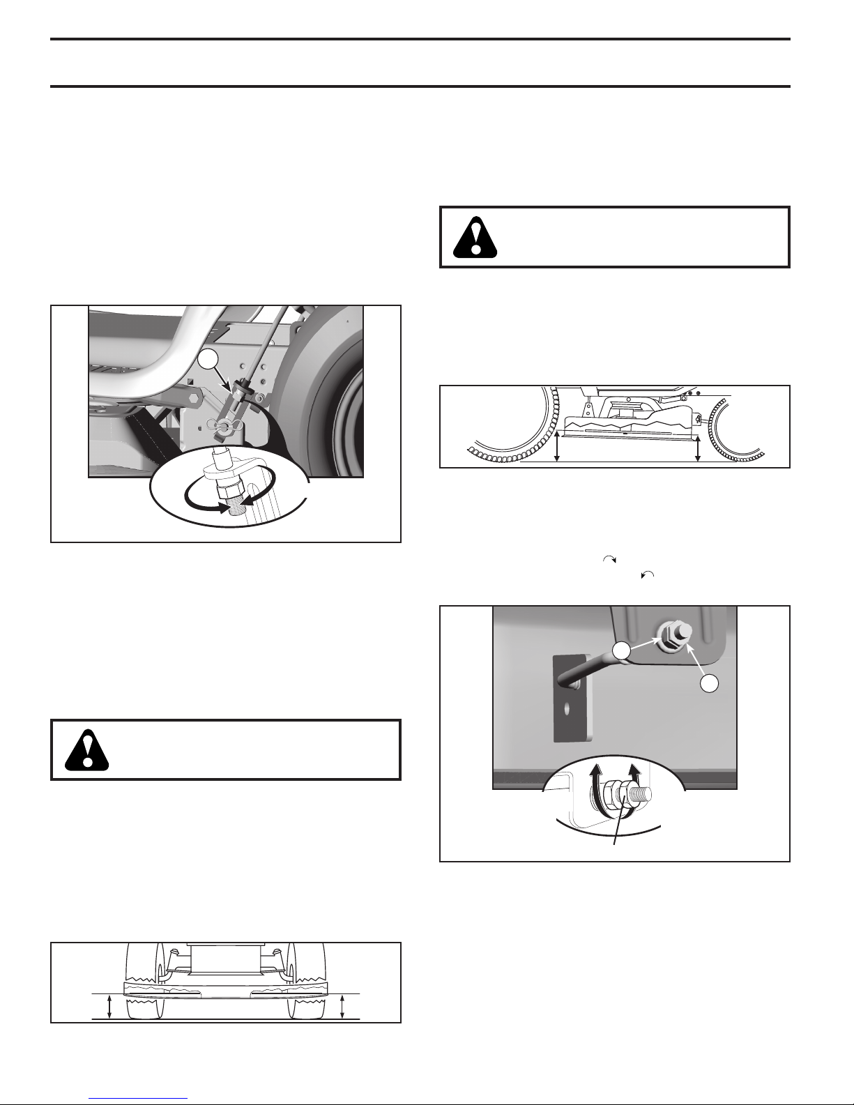
VISUAL SIDE-TO-SIDE ADJUSTMENT (See Fig. 37)
• With all tires properly inflated and if your lawn appears
unevenly cut, determine which side of mower is cutting
lower.
• With a 3/4" or adjustable wrench, turn lift link adjustment
nut (A) to the left to lower LH side of mower, or, to the
right to raise LH side of mower.
A
TURN NUT
RIGHT TO
RAISE
MOWER
Fig. 37
NOTE: Each full turn of adjustment nut will change mower
height about 3/16" (4,7 mm).
• Test your adjustment by mowing some uncut grass and
visually checking the appearance. Readjust, if necessary, until you are satisfied with the results.
PRECISION SIDE-TO-SIDE ADJUSTMENT (See Fig. 38)
• With all tires properly inflated, park tractor on level
ground or driveway.
TURN NUT
LEFT TO
LOWER
MOWER
FRONT-TO-BACK ADJUSTMENT (See Figs. 39 & 40)
IMPORTANT: Deck must be level side-to-side.
To obtain the best cutting re sults, the mower blades should
be adjusted so the front tip is 1/8" to 1/2" (3,1 to 12,7 mm)
lower than the rear tip when the mower is in its highest
position.
CAUTION: Blades are sharp. Protect
your hands with gloves and/or wrap
blade with heavy cloth.
• Raise mower to highest position.
• Position blade so the tip is pointing straight forward.
Measure distance (B) to the ground at front and rear
tip of the blade.
• If front tip of blade is not 1/8" to 1/2" (3,1 to 12,7 mm)
lower than the rear tip, go to the front of tractor.
B
B
Fig. 39
• With an 11/16" or adjustable wrench, loosen jam nut A
several turns to clear adjustment nut B.
• With a 3/4" or adjustable wrench, turn front link adjustment nut (B) clockwise ( ) (tighten) to raise the front of
mower, or, counterclockwise ( ) (loosen) to lower the
front mower.
B
A
CAUTION: Blades are sharp. Protect
your hands with gloves and/or wrap
blade with heavy cloth.
• Raise mower to its highest position.
• At both sides of mower, position blade at side and
measure the distance (A) from bottom edge of blade to
the ground. The distance should be the same on both
sides.
• If adjustment is necessary, see steps in Visual Adjustment instructions above.
• Recheck measurements, adjust if necessary until both
sides are equal.
AA
Fig. 38
TIGHTEN ADJUST
NUT "B" TO
RAISE MOWER
LOOSEN JAM NUT "A" FIRST
LOOSEN ADJUST
NUT "B" TO
LOWER MOWER
Fig. 40
NOTE: Each full turn of the adjustment nut will change
mower height about 1/8" (3,1 mm).
• Recheck measurements, adjust if necessary until front
tip of blade is 1/8" to 1/2" (3,1 to 12,7 mm) lower than
the rear tip.
• Hold adjustment nut in position with wrench and tighten
jam nut securely against adjustment nut.
24
Page 25
SERVICE AND ADJUSTMENTS
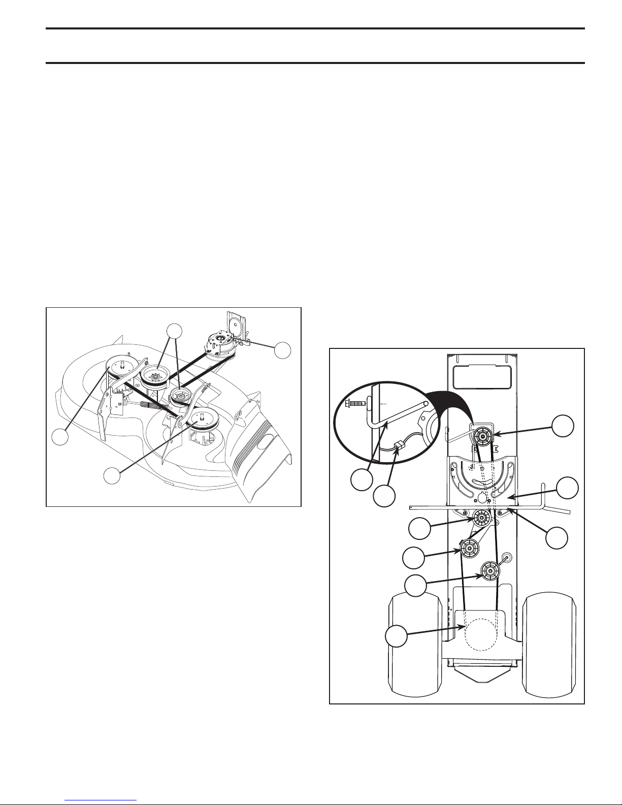
TO REPLACE MOWER BLADE DRIVE BELT
(See Fig. 41)
MOWER DRIVE BELT REMOVAL
• Park tractor on a level surface. En gage parking brake.
• Lower attachment lift lever to its lowest position.
• Remove any dirt or grass clippings which may have
accumulated around mandrels and entire upper deck
surface.
• Remove belt from electric clutch pulley (M), both mandrel pulleys (R) and all idler pulleys (V).
MOWER DRIVE BELT INSTALLATION
• Install belt around all mandrel pulleys (R) and around
idler pulleys (V) as shown.
• Install belt onto electric clutch pulley (M).
IMPORTANT: Check belt for proper routing in all mower
pulley grooves.
• Raise attachment lift lever to highest position.
V
M
• Remove belt downward from engine pulley and around
electric clutch (G).
• Slide belt toward rear of tractor, off the steering plate
(H) and remove from tractor.
BELT INSTALLATION -
• Install new belt from tractor rear to front, over the steering plate (H) and above clutch brake pedal shaft (J).
• Pull belt toward front of tractor and roll belt around
electric clutch and onto engine pulley (G).
• Pull belt toward rear of tractor. Carefully work belt down
around transmission cooling fan and onto the input
pulley (F). Be sure belt is inside the belt keeper.
• Install belt on centerspan idler (E).
• Install belt through stationary idler (C) and clutch ing
idler (D).
• Reinstall anti-rotation link (B) on right side of tractor.
Tighten securely.
• Reconnect clutch harness (A).
• Make sure belt is in all pulley grooves and in side all
belt guides and keep ers.
• Install mower (See “TO IN STALL MOWER” in this
sec tion of manual).
R
R
Fig. 41
TO REPLACE MOTION DRIVE BELT
(See Fig. 42)
Park the tractor on level surface. En gage parking brake.
For as sis tance, there is a belt installation guide decal on
bottom side of left footrest.
BELT REMOVAL -
• Remove mower (See “TO RE MOVE MOWER” in this
section of manual).
NOTE: Observe entire motion drive belt and position of all
belt guides and keepers.
• Disconnect clutch wire harness (A).
• Remove anti-rotation link (B) on right side of tractor.
• Remove belt from stationary idler (C) and clutching
idler (D).
• Remove belt from centerspan idler (E).
• Pull belt slack toward rear of trac tor. Carefully remove
belt up wards from trans mis sion input pulley and over
cooling fan blades (F).
G
B
A
C
D
E
F
Fig. 42
H
J
25
Page 26
SERVICE AND ADJUSTMENTS
TO CHECK BRAKE
If tractor requires more than five (5) feet (1,5 m) to stop at
highest speed in high est gear on a level, dry concrete or
paved surface, then brake must be serviced.
You may also check brake by:
1. Park tractor on a level, dry concrete or paved surface,
depress brake pedal all the way down and engage
parking brake.
2. Disengage transmission by placing freewheel control
in “transmission disengaged” position. Pull freewheel
control out and into the slot and release so it is held in
the disengaged position.
The rear wheels must lock and skid when you try to manually
push the tractor forward. If the rear wheels rotate, then the
brake needs to be serviced. Contact a qualified service center.
FRONT WHEEL TOE-IN/CAM BER
Your new tractor front wheel toe-in and camber is set at the
factory and is normal. The front wheel toe-in and camber
are not adjustable. If damage has occurred to affect the
factory set front wheel toe-in or camber, contact a qualified
service center.
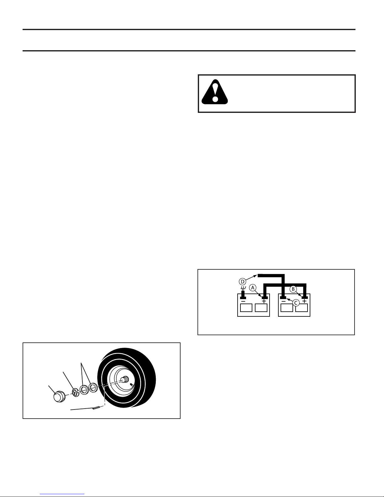
TO REMOVE WHEEL FOR REPAIRS
(See Fig. 43)
• Block up axle securely.
• Remove axle cover, retaining ring and washers to allow
wheel removal (rear wheel contains a square key - Do
not lose).
• Repair tire and reassemble.
• On rear wheels only: align grooves in rear wheel hub
and axle. Insert square key.
• Replace washers and snap retaining ring securely in
axle groove.
• Replace axle cover.
NOTE: To seal tire punctures and prevent flat tires due
to slow leaks, tire sealant may be purchased from your
local parts dealer. Tire sealant also prevents tire dry rot
and corrosion.
TO START ENGINE WITH A WEAK BATTERY
(See Fig. 44)
WARNING: Lead-acid batteries gen er ate
ex plo sive gases. Keep sparks, flame and
smoking ma te ri als away from bat ter ies.
Always wear eye pro tec tion when around
batteries.
If your battery is too weak to start the engine, it should be
recharged. (See "BATTERY" in the MAINTENANCE sec tion of this man u al).
If “jumper ca bles” are used for emer gen cy starting, follow
this pro ce dure:
IMPORTANT: YOUR TRACTOR IS EQUIPPED WITH A
12 VOLT SYSTEM. THE OTHER VEHICLE MUST ALSO
BE A 12 VOLT SYSTEM. DO NOT USE YOUR TRACTOR
BATTERY TO START OTHER VEHICLES.
TO ATTACH JUMPER CABLES -
• Connect one end of the RED cable to the POSITIVE
(+) terminal of each battery(A-B), taking care not to
short against tractor chassis.
• Connect one end of the BL ACK ca ble to the NEGA TIVE
(-) terminal (C) of fully charged battery.
• Connect the other end of the BLACK cable (D) to good
chassis ground, away from fuel tank and bat tery.
TO REMOVE CABLES, REVERSE ORDER -
• BLACK cable first from chassis and then from the fully
charged battery.
• RED cable last from both batteries.
WEAK OR DEAD
BATTERY
FULLY CHARGED
BATTERY
Fig. 44
WASH ERS
RE TAIN ING
RING
AXLE COVER
SQUARE KEY (REAR
WHEEL ONLY)
Fig. 43
26
Page 27
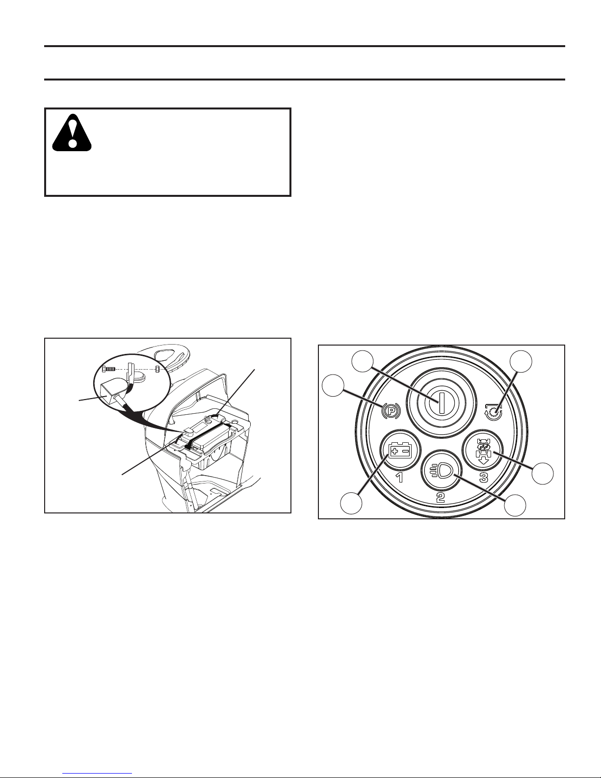
SERVICE AND ADJUSTMENTS
REPLACING BATTERY (See Fig. 45)
WARNING: Do not short battery ter mi nals by allowing a wrench or any other
object to contact both terminals at the
same time. Before connecting battery,
remove metal bracelets, wristwatch
bands, rings, etc. Positive terminal
must be connected first to prevent
sparking from ac ci den tal grounding.
• Lift hood to raised position.
• Remove terminal cover.
• Disconnect BLACK battery cable then RED battery
cable and carefully remove battery from tractor.
• Install new battery with terminals in same position as
old battery.
• Reinstall terminal cover.
• First connect RED battery cable to positive (+) battery
terminal with bolt and nut as shown. Tighten securely.
• Connect BL ACK grounding cable to negative (-) bat tery
terminal with remaining bolt and nut. Tighten securely
• Close hood.
NEGATIVE
(BLACK)
CABLE
FAULTS
• The SSI Button (F) will blink red for two seconds if the
wrong passcode has been entered.
• The park brake symbol (CC) will be lit if the parking
brake has not been engaged during a start attempt.
• The blade switch symbol (EE) will blink if the attachment
clutch control is not in the "DISENGAGED" position
during a start attempt.
• The Reverse Operation System (ROS) button (G) will
blink when there is a fault with the Reverse Operation
System. See "Reverse Operation System" in the Operation section of this manual.
• After the first unsuccessful start attempt, the Battery
Indicator Button (I) will blink for two (2) seconds and then
stay lit. This indicates that the battery voltage is below
normal operating level. While engine is in operation,
this light may also indicate a charging system failure.
• The Headlight Button (H) will blink when one or both of
the headlight bulbs fail.
• All indicator lights will blink in the event the engine shuts
off for unknown reasons; for example, if the engine has
run out of fuel.
F
EE
TERMINAL
COVER
POSITIVE
(RED)
CABLE
Fig. 45
SMARTSWITCH IGNITION SYSTEM LIGHTS
(See Fig. 46)
The SmartSwitch System is equipped with courtesy lights
that are used to indicate system functions or faults.
FUNCTIONS
• The SmartSwitch Ignition (SSI) Button (F) will blink blue
while waiting for the correct passcode to be entered.
The SSI button will blink green when tractor is ready to
start and remain solid green while running.
• The Reverse Operation System (ROS) button (G) will
be lit when Reverse Operation System is in use.
• The Headlight button (H) will remain lit while headlights
are in use.
• During normal operation, the Battery Indicator Button (I)
will not be lit.
CC
G
I
Fig. 46
H
TO REPLACE HEADLIGHT BULB
• Raise hood.
• Pull bulb holder out of the hole in the backside of the
grill.
• Replace bulb in holder and push bulb holder securely
back into the hole in the backside of the grill.
• Close hood.
INTERLOCKS AND RELAYS
Loose or damaged wiring may cause your tractor to run
poorly, stop running, or prevent it from starting.
• Check wiring.
TO REPLACE FUSE
Replace with 30 amp automotive-type plug-in fuse. The
fuse holder is located behind the dash.
27
Page 28
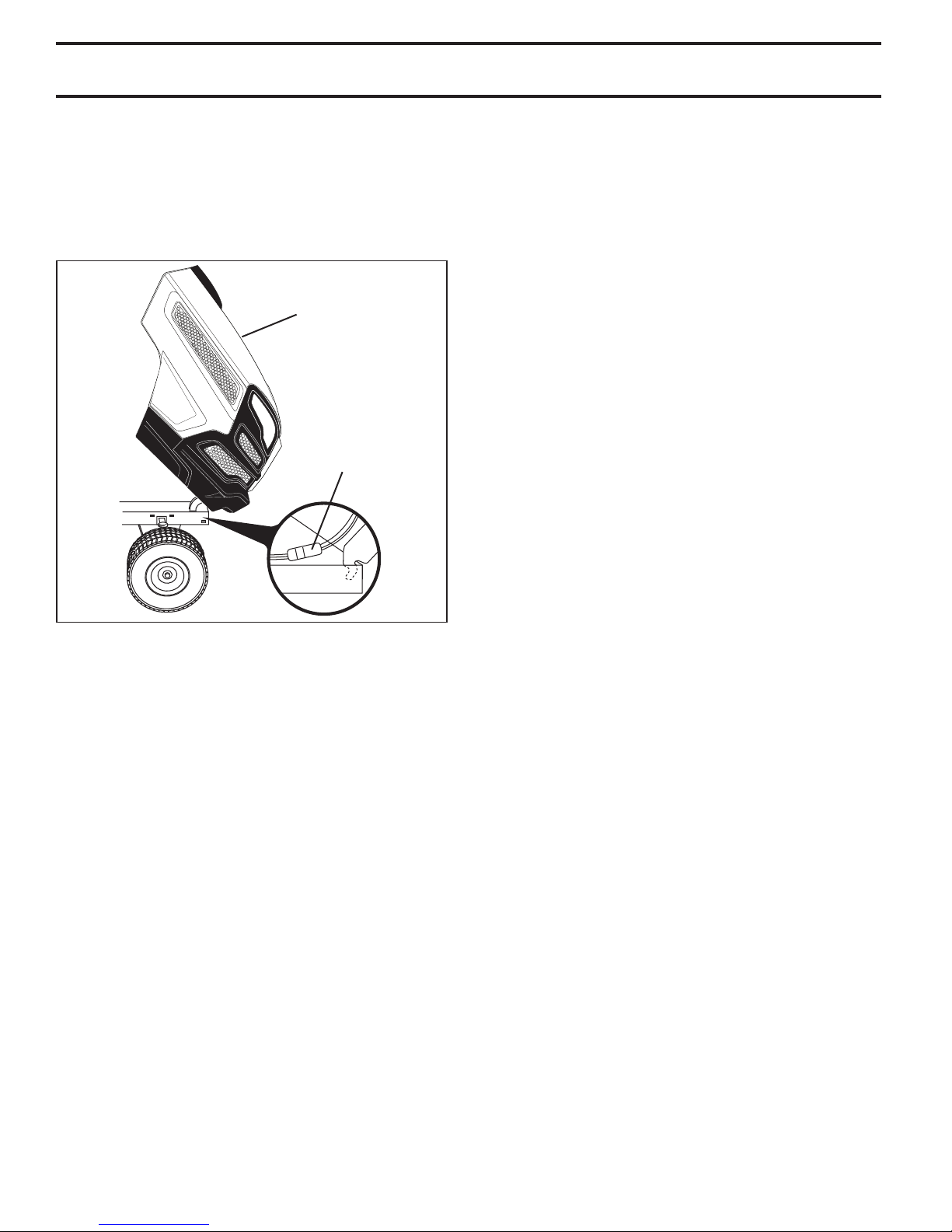
SERVICE AND ADJUSTMENTS
TO REMOVE HOOD AND GRILL ASSEMBLY
(See Fig. 47)
• Raise hood.
• Unsnap headlight wire connector.
• Stand in front of tractor. Grasp hood at sides, tilt toward
engine and lift off of tractor.
• To replace, reverse above procedure.
HOOD
HEADLIGHT
WIRE
CONNECTOR
07002
Fig. 47
ENGINE
TO AD JUST THROTTLE CON TROL CABLE
The throttle control has been preset at the factory and
ad just ment should not be necessary. If adjustment is nec es sary, see engine manual.
TO AD JUST CHOKE CON TROL
The choke control has been preset at the factory and ad just ment should not be necessary. If adjustment is necessary,
see engine manual.
TRANSMISSION
REMOVAL/RE PLACE MENT
Should your transmission require removal for service or
re place ment, it should be purged after reinstallation and
before operating the tractor. See “PURGE TRANS MIS SION”
in the Operation section of this manual.
28
Page 29

STORAGE
Immediately prepare your tractor for storage at the end
of the season or if the tractor will not be used for 30 days
or more.
WARNING: Never store the trac tor with
gas o line in the tank inside a building
where fumes may reach an open flame
or spark. Allow the engine to cool before
storing in any en clo sure.
TRACTOR
Remove mower from tractor for winter storage. When mower
is to be stored for a period of time, clean it thor oughly, remove
all dirt, grease, leaves, etc. Store in a clean, dry area.
• Clean entire tractor. (See “CLEANING” in the
Main te nance section of this manual.)
• Inspect and replace belts, if necessary. (See belt
re place ment instructions in the Service and Adjustments
section of this manual.)
• Lubricate as shown in the Maintenance section of this
man ual.
• Be sure that all nuts, bolts and screws are securely
fastened. Inspect moving parts for damage, breakage
and wear. Replace if necessary.
• Touch up all rusted or chipped paint surfaces; sand
lightly before painting.
BATTERY
• Fully charge the battery for storage.
• After a period of time in storage, battery may require
recharging.
• To help prevent corrosion and power leakage during
long periods of storage, battery cables should be
dis con nect ed and battery cleaned thoroughly. (See
“TO CLEAN BATTERY AND TERMINALS” in the
Maintenance sec tion of this manual.)
• After cleaning, leave cables disconnected and place
cables where they cannot come in contact with battery
terminals.
• If battery is removed from tractor for storage, do not
store battery directly on concrete or damp surfaces.
• If unit is equipped with battery indicator/charging
plug, an optional charging unit may be purchased and
connected to the unit to charge the battery during long
term storage. Inspect and clean the battery terminals
as needed prior to long term storage with charger
connected.
ENGINE
FUEL SYSTEM
IMPORTANT: IT IS IMPORTANT TO PREVENT GUM DEPOSITS
FROM FORMING IN ES SEN TIAL FUEL SYSTEM PARTS SUCH
AS CARBURETOR, FUEL FIL TER, FUEL HOSE, OR TANK
DURING STORAGE. ALSO, EXPERIENCE INDICATES THAT
ALCOHOL BLENDED FUELS (CALLED GASOHOL OR USING
ETHANOL OR METHANOL) CAN ATTRACT MOIS TURE WHICH
LEADS TO SEPARATION AND FOR MA TION OF ACIDS DURING
STOR AGE. ACIDIC GAS CAN DAMAGE THE FUEL SYSTEM
OF AN ENGINE WHILE IN STORAGE.
• Empty the fuel tank by starting the engine and let it run
until the fuel lines and carburetor are empty.
• Never use engine or carburetor cleaner products in
the fuel tank or permanent damage may occur.
• Use fresh fuel next season.
NOTE: Fuel stabilizer is an acceptable alternative in
minimizing the formation of fuel gum deposits during stor age.
Add stabilizer to gasoline in fuel tank or storage container.
Always follow the mix ratio found on stabilizer container.
Run engine at least 10 minutes after adding stabilizer to
allow the stabilizer to reach the carburetor. Do not empty
the gas tank and carburetor if using fuel stabilizer.
ENGINE OIL
Drain oil (with engine warm) and replace with clean engine
oil. (See “ENGINE” in the Maintenance section of this
man ual.)
CYLINDER(S)
• Remove spark plug(s).
• Pour one ounce (
hole(s) into cylinder(s).
• Turn ignition key to “START” position for a few seconds
to distribute oil.
• Replace with new spark plug(s).
29.5 mL) of oil through spark plug
OTHER
• Do not store gasoline from one season to another.
• Replace your gasoline can if your can starts to rust.
Rust and/or dirt in your gasoline will cause problems.
• If possible, store your tractor indoors and cover it to
give protection from dust and dirt.
• Cover your tractor with a suitable protective cover that
does not retain moisture. Do not use plastic. Plastic
cannot breathe which allows condensation to form and
will cause your tractor to rust.
IMPORTANT: NEVER COVER TRACTOR WHILE EN GINE
AND EXHAUST AREAS ARE STILL WARM.
29
Page 30

TROUBLESHOOTING POINTS
PROBLEM CAUSE CORRECTION
Will not start
1. Out of fuel. 1. Fill fuel tank.
2. Engine flooded. 2. Wait several minutes before attempting to start.
3. Bad spark plug. 3. Replace spark plug.
4. Dirty air filter. 4. Clean/replace air filter.
5. Dirty fuel filter. 5. Replace fuel filter.
6. Water in fuel. 6. Empty fuel tank and carburetor, refill tank with fresh
gasoline and replace fuel filter.
7. Loose or damaged wiring. 7. Check all wiring.
8. Engine valves out of adjustment. 8. Contact an authorized service center/department.
Hard to start
Engine will not turn
over
Engine clicks but
will not start
Loss of power
1. Dirty air filter. 1. Clean/replace air filter.
2. Bad spark plug. 2. Replace spark plug.
3. Weak or dead battery. 3. Recharge or replace battery.
4. Dirty fuel filter. 4. Replace fuel filter.
5. Stale or dirty fuel. 5. Empty fuel tank and refill tank with fresh, clean gas.
6. Loose or damaged wiring. 6. Check all wiring.
7. Engine valves out of adjustment. 7. Contact an authorized service center/department.
1. Brake pedal not depressed. 1. Depress brake pedal.
2. Attachment clutch is engaged. 2. Disengage attachment clutch.
3. Weak or dead battery. 3. Recharge or replace battery.
4. Blown fuse. 4. Replace fuse.
5. Corroded battery terminals. 5. Clean battery terminals.
6. Loose or damaged wiring. 6. Check all wiring.
7. Faulty ignition switch. 7. Check/replace ignition switch.
8. Faulty solenoid or starter. 8. Check/replace solenoid or starter.
9. Faulty operator presence switch(es). 9. Contact an authorized service center/department.
1. Weak or dead battery. 1. Recharge or replace battery.
2. Corroded battery terminals. 2. Clean battery terminals.
3. Loose or damaged wiring. 3. Check all wiring.
4. Faulty solenoid or starter. 4. Check/replace solenoid or starter.
1. Cutting too much grass/too fast. 1. Raise cutting height/reduce speed.
2.
Throttle in cold weather starting position (
3. Build-up of grass, leaves, trash under mower. 3. Clean underside of mower housing.
4. Dirty air filter. 4. Clean/replace air filter.
5. Low oil level/dirty oil. 5. Check oil level/change oil.
6. Faulty spark plug. 6. Clean and regap or change spark plug.
7. Dirty fuel filter. 7. Replace fuel filter.
8. Stale or dirty fuel. 8. Empty fuel tank and refill tank with fresh, clean gas.
9. Water in fuel. 9. Empty fuel tank and carburetor, refill tank with fresh
10. Spark plug wire loose. 10. Connect and tighten spark plug wire.
11. Dirty engine air screen/fins. 11. Clean engine air screen/fins.
12. Dirty/clogged muffler. 12. Clean/replace muffler.
13. Loose or damaged wiring. 13. Check all wiring.
14. Engine valves out of adjustment. 14. Contact an authorized service center/department.
2.
).
Move throttle control to fast position ( ).
gasoline and replace fuel filter.
Excessive
vibration
1. Worn, bent or loose blade. 1. Replace blade. Tighten blade bolt.
2. Bent blade mandrel. 2. Replace blade mandrel.
3. Loose/damaged part(s). 3. Tighten loose part(s). Replace damaged parts.
30
Page 31

TROUBLESHOOTING POINTS
PROBLEM CAUSE CORRECTION
Engine continues to
run when operator
leaves seat with
attachment clutch
engaged
1. Faulty operator-safety presence control
system.
1. Check wiring, switches and connections. If not
corrected, contact an authorized service center/
department.
CAUTION: DO NOT operate machine until
problem is corrected.
Poor cut - uneven
Mower blades will
not rotate
Poor grass
discharge
Headlight(s) not
working
(if so equipped)
1. Worn, bent or loose blade. 1. Replace blade. Tighten blade bolt.
2. Mower deck not level. 2. Level mower deck.
3. Buildup of grass, leaves, trash under mower. 3. Clean underside of mower housing.
4. Bent blade mandrel. 4. Replace blade mandrel.
5. Clogged mower deck vent holes from
buildup of grass, leaves, and trash around
mandrels.
1. Obstruction in clutch mechanism. 1. Remove obstruction.
2. Worn/damaged mower drive belt. 2. Replace mower drive belt.
3. Frozen idler pulley. 3. Replace idler pulley.
4. Frozen blade mandrel. 4. Replace blade mandrel.
1. Engine speed too slow. 1. Place throttle control in “FAST” position.
2. Travel speed too fast. 2. Shift to slower speed.
3. Wet grass. 3. Allow grass to dry before mowing.
4. Mower deck not level. 4. Level mower deck.
5. Low/uneven tire air pressure. 5. Check tires for proper air pressure.
6. Worn, bent or loose blade. 6. Replace blade. Tighten blade bolt.
7. Buildup of grass, leaves, trash under mower. 7. Clean underside of mower housing.
8. Mower drive belt worn. 8. Replace mower drive belt.
9. Blades improperly installed. 9. Reinstall blades sharp edge down.
10. Improper blades used. 10. Replace with blades listed in parts manual.
11. Clogged mower deck vent holes from buildup
of grass, leaves, trash around mandrels.
1. Switch is “OFF”. 1. Turn switch “ON”.
2. Bulb(s) or lamp(s) burned out. 2. Replace bulb(s) or lamp(s).
3. Faulty light switch. 3. Check/replace SmartSwitch Ignition switch.
4. Loose or damaged wiring. 4. Check wiring and connections.
5. Blown fuse. 5. Replace fuse.
5. Clean around mandrels to open vent holes.
11. Clean around mandrels to open vent holes.
Battery will not
charge
Loss of drive
Engine "backfires”
when turning
engine “OFF”
Engine dies when
tractor is shifted
into reverse
1. Bad battery cell(s). 1. Replace battery.
2. Poor cable connections. 2. Check/clean all connections.
3. Faulty regulator (if so equipped). 3. Replace regulator.
4. Faulty alternator. 4. Replace alternator.
1. Freewheel control in “disengaged” position. 1. Place freewheel control in “engaged” position.
2. Debris on steering plate (if equipped). 2. See "CLEANING" in the Maintenance section.
3. Motion drive belt worn, damaged, or broken. 3. Replace motion drive belt.
4. Air trapped in transmission during
shipment or servicing.
5. Axle key missing. 5. Install axle key at rear wheel. See "TO REMOVE
1. Engine throttle control not set between
half and full speed (fast) position before
stopping engine.
1. Reverse operation system (ROS) is not "ON"
while mower or other attachment is engaged.
4. Purge transmission.
WHEEL" in the Service and Adjustments section.
1. Move throttle control between half and full speed
(fast) position before stopping engine.
1. Turn ignition key to ROS "ON" position. See
Operation section.
31
Page 32
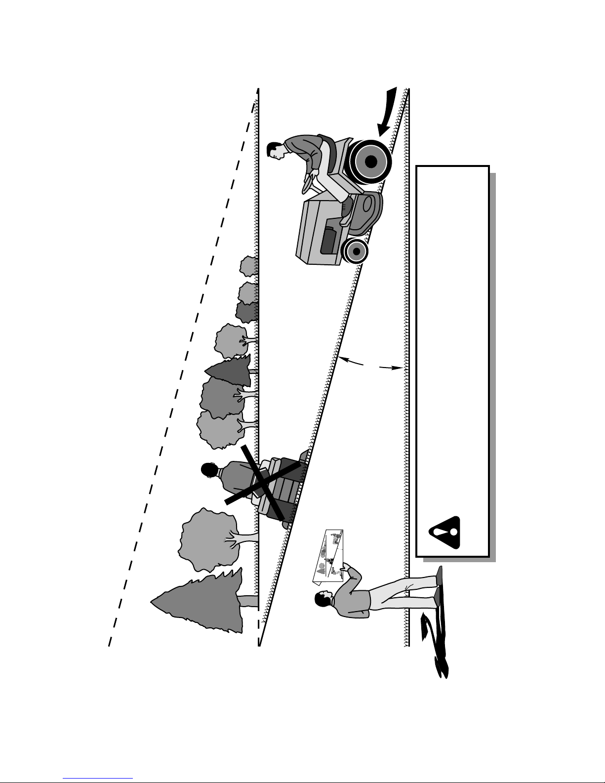
15 DEGREES MAX.
FOLD ALONG DOTTED LINE
THIS IS A 15 DEGREE SLOPE
ONLY RIDE UP AND DOWN HILL,
NOT ACROSS HILL
SUGGESTED GUIDE FOR SIGHTING SLOPES FOR SAFE OPERATION
WARNING: To avoid serious injury, operate your tractor up and
down the face of slopes, never across the face. Do not mow
slopes greater than 15 degrees. Make turns gradually to prevent
tipping or loss of control. Exercise extreme caution when
changing direction on slopes.
1. Fold this page along dotted line indicated above.
2. Hold page before you so that its left edge is vertically parallel to a tree
trunk or other upright structure.
3. Sight across the fold in the direction of hill slope you want to measure.
4. Compare the angle of the fold with the slope of the hill.
32
Page 33

SERVICE NOTES
33
Page 34

SERVICE NOTES
34
Page 35

SERVICE NOTES
35
Page 36

04/22/2015 TH
 Loading...