


Gasoline containing up to 10% ethanol (E10) is acceptable for use in this machine.
The use of any gasoline exceeding 10% ethanol (E10) will void the product warranty.
532 44 30-86 Rev. 6
Operator’s Manual
ST 121E
Please read the owner's manual carefully and make sure you
understand the instructions before using the machine.
English
CONGRATULATIONS on your purchase of a new snow thrower. It has been designed, engineered and man u fac tured to
give best possible dependability and per for mance.
Should you experience any problem you cannot easily remedy, please contact your nearest authorized service center. We
have competent, well-trained tech ni cians and the proper tools to service or repair this unit.
Please read and retain this manual. The instructions will enable you to assemble and maintain your snow thrower prop er ly.
Always observe the “SAFETY RULES”.
Safe Operation Practices for Walk-Behind Snow Throwers
IMPORTANT: This snow thrower is capable of amputating hands and feet and throwing objects. Failure to observe the
following safety instructions could result in serious injury.
Look for this symbol to point out im por tant
safety precautions. It means CAUTION!!! BE COME ALERT!!! YOUR SAFE TY IS IN VOLVED.
WARNING: Always disconnect spark plug wire
and place it where it can not con tact plug in order
to pre vent ac ci den tal start ing when setting up,
trans port ing, ad just ing or making re pairs.
WARNING: This snow thrower is for use on
sidewalks, driveways and other ground level surfaces. Caution should be exercised while using
on sloping surfaces. Do not use snow thrower
on surfaces above ground level such as roofs
of residences, garages, porch es or other such
structures or buildings.
Training
1. Read, understand and follow all instructions on the
machine and in the manual(s) before operating this
unit. Be thoroughly familiar with the controls and the
proper use of the equipment. Know how to stop the
unit and disengage the controls quickly.
2. Never allow children to operate the equipment. Never
allow adults to operate the equipment without proper
instruction.
3. Keep the area of operation clear of all persons, particularly small children.
4. Exercise caution to avoid slipping or falling, especially
when operating the snow thrower in reverse.
Preparation
1. Thoroughly inspect the area where the equipment is
to be used and remove all doormats, sleds, boards,
wires, and other foreign objects.
2. Ensure the control bar is released before starting the
engine.
3. Do not operate the equipment without wearing adequate
winter garments. Avoid loose fitting clothing that can
get caught in moving parts. Wear footwear that will
improve footing on slippery surfaces.
4. Handle fuel with care; it is highly flammable
(a) Use an approved fuel container.
(b) Never add fuel to a running engine or hot engine.
(c) Fill fuel tank outdoors with extreme care. Never fill
fuel tank indoors.
WARNING: Snow throwers have ex posed rotating
parts, which can cause severe injury from contact,
or from material thrown from the discharge chute.
Keep the area of operation clear of all persons,
small children and pets at all times including
startup.
CAUTION: Muffler and other engine parts become
extremely hot during operation and remain hot
after engine has stopped. To avoid severe burns
on contact, stay away from these areas.
WARNING: Engine exhaust, some of its con stit u-
ents, and certain vehicle com po nents contain or
emit chem i cals known to the State of Cal i for nia
to cause can cer and birth defects or oth er re produc tive harm.
(d) Never fill containers inside a vehicle or on a truck or
trailer bed with a plastic liner. Always place containers
on the ground, away from your vehicle, before filling.
(e) When practical, remove gas-powered equipment
from the truck or trailer and refuel it on the ground.
If this is not possible, then refuel such equipment
on a trailer with a portable container, rather than
from a gasoline dispenser nozzle.
(f) Keep the nozzle in contact with the rim of the fuel
tank or container opening at all times, until refueling
is complete. Do not use a nozzle lock-open device.
(g) Replace gasoline cap securely and wipe up spilled
fuel.
(h) If fuel is spilled on clothing, change clothing
immediately.
5. Use extension cords and receptacles as specified by
the manufacturer for all units with electric drive motors
or electric starting motors.
6. Never attempt to make any adjustments while the
engine (motor) is running (except when specifically
recommended by manufacturer).
7. Always wear safety glasses or eye shields during operation or while performing an adjustment or repair to
protect eyes from foreign objects that may be thrown
from the machine.
8. Let engine and machine adjust to outdoor temperatures
before starting to clear snow.
2

Operation
1. Do not put hands or feet near or under rotating parts.
Keep clear of the discharge opening at all times.
2. Exercise extreme caution when operating on or crossing gravel drives, walks, or roads. Stay alert for hidden
hazards or traffic.
3. After striking a foreign object, stop the engine (motor),
disconnect the cord on electric motors, thoroughly
inspect the snow thrower for any damage, and repair
the damage before restarting and operating the snow
thrower. Remove key.
4. If the unit should start to vibrate abnormally, stop the
engine (motor) and check immediately for the cause.
Vibration is generally a warning of trouble.
5. Stop the engine (motor) whenever you leave the
operating position, before unclogging the auger housing or discharge chute, and when making any repairs,
adjustments or inspections.
6. When cleaning, repairing or inspecting the snow thrower,
stop the engine and make certain the auger blades and
all moving parts have stopped. Remove key.
7. Do not run the engine indoors, except when starting
the engine and for transporting the snow thrower in or
out of the building. Open the outside doors; exhaust
fumes are dangerous.
8. Exercise extreme caution when operating on slopes.
9. Never operate the snow thrower without proper guards,
and other safety protective devices in place and working.
10. Never direct the discharge toward people or areas
where property damage can occur. Keep children and
others away.
11. Do not overload the machine capacity by attempting
to clear snow at too fast a rate.
12. Never operate the machine at high transport speeds
on slippery surfaces. Look behind and use care when
operating in reverse.
13. Disengage power to the auger blades when snow
thrower is transported or not in use.
14. Use only attachments and accessories approved by
the manufacturer of the snow thrower.
15. Never operate the snow thrower without good visibility
or light. Always be sure of your footing, and keep a firm
hold on the handles. Walk; never run.
16. Never touch a hot engine or muffler.
Maintenance and Storage
1. Check shear bolts and other bolts at frequent intervals
for proper tightness to be sure the equipment is in safe
working condition.
2. Never store the machine with fuel in the fuel tank inside
a building where ignition sources are present such as
hot water heaters, space heaters, or clothes dryers.
Allow the engine to cool before storing in any enclosure.
3. Always refer to operator’s manual for important details
if the snow thrower is to be stored for an extended
period.
4. Maintain or replace safety and instruction labels, as
necessary.
5. Run the machine a few minutes after throwing snow
to prevent freeze-up of the collector/impeller.
SERIAL NUMBER: ___________________________
DATE OF PURCHASE: _______________________
THE MODEL AND SERIAL NUMBERS WILL BE FOUND
ON A DECAL ATTACHED TO THE REAR OF THE SNOW
THROWER HOUSING (Figure 1).
YOU SHOULD RECORD BOTH SERIAL NUMBER AND
DATE OF PURCHASE AND KEEP IN A SAFE PLACE
FOR FUTURE REFERENCE.
PRODUCT
MODEL NUMBER / NUMERO DE MODELE KG KW RPM
FOR SERVICE CALL/POUR APPELER LE SERVICE
1-800-448-7543
ASSEMBLED IN U.S.A.
ORANGEBURG, SC 29116
MAINTENANCE LEVEL
PRODUIT
NIVEAU DE MAINTENANCE
000000000 00
00000000 000 000 000 0000
CONFORMS TO ANSI B71.3-2005 SAFETY STANDARDS
CONFORME AUX NORMES DE SECURITE ANSI B71.3-2005
SERIAL NUMBER
NUMERO DE SERIE
000000A 000000
YEAR
000000
Figure 1
CUSTOMER RESPONSIBILITIES
• Read and observe the safety rules.
• Follow a regular schedule in maintaining, caring for
and using your snow thrower.
• Follow the instructions under “Maintenance” and “Stor age” sec tions of this manual.
Clearing a Clogged Discharge Chute
Hand contact with the rotating auger blades inside
the discharge chute is the most common cause
of injury associated with snow throwers. Never
use your hand to clean out the discharge chute.
To clear the chute:
1. SHUT THE ENGINE OFF!
2. Wait 10 seconds to be sure the auger blades have
stopped rotating.
3. Always use a clearing tool at least 15 inches long.
PRODUCT SPECIFICATIONS
Gasoline Capacity 1.6 Quarts (1,5 Liters)
and Type: Unleaded Regular only
Oil Type SAE 30 (above 50°F)
(API SG–SL): SAE 5W-30 or 10W-30
(32° to 50°F)
SAE 5W-30 (below 32°F)
Oil Capacity: 18 Ounces (0,53 Liters)
Spark Plug: F6RTC
Gap: 0.030" (0,762 mm)
3
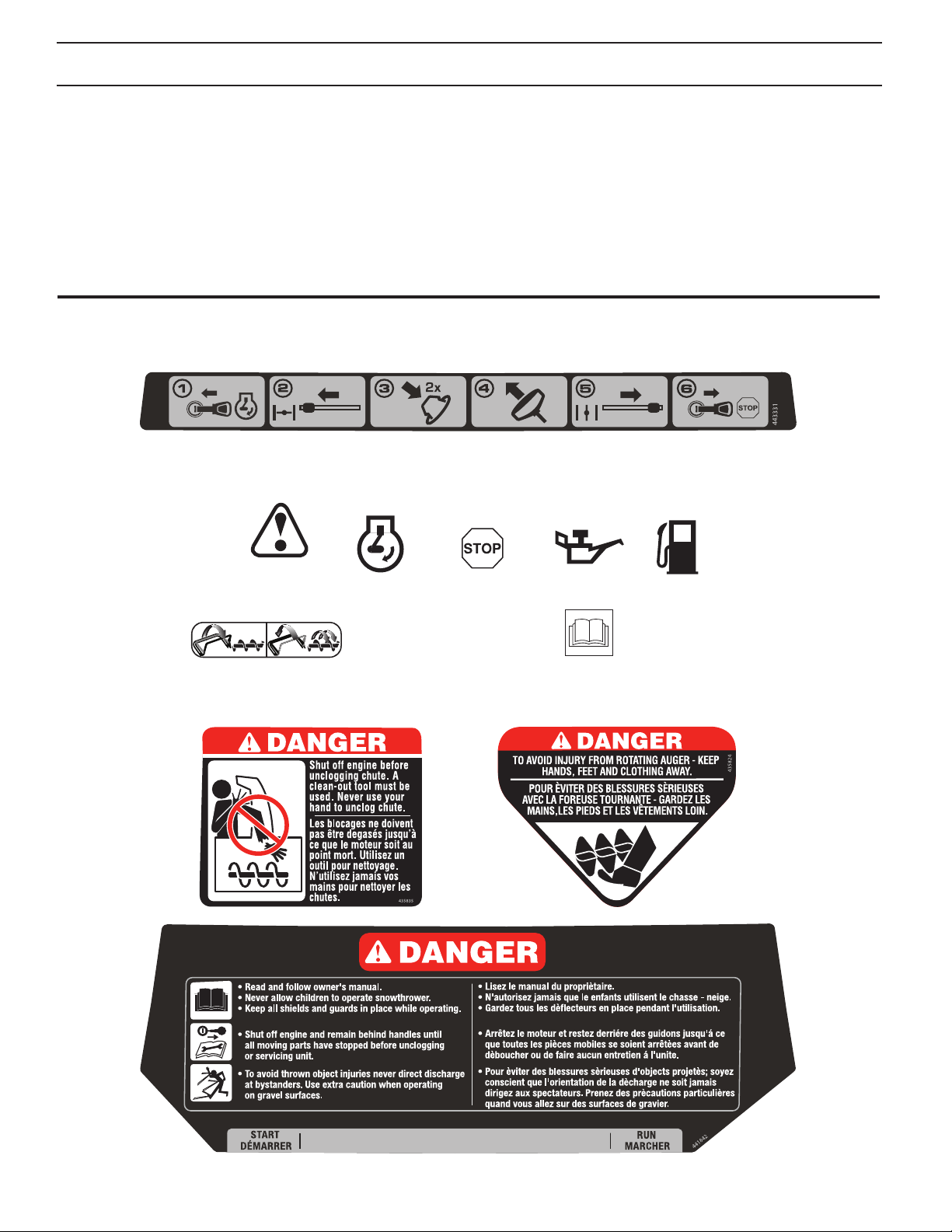
TABLE OF CONTENTS
SAFETY RULES ........................................................ 2-3
PRODUCT SPECIFICATIONS ...................................... 3
CUSTOMER RESPONSIBILITIES ................................ 3
SAFETY AND INSTRUCTIONAL DECALS ................. 4
ASSEMBLY ................................................................ 5-6
OPERATION ............................................................ 8-11
MAINTENANCE ..................................................... 12-16
STORAGE ................................................................... 17
TROUBLESHOOTING ................................................ 18
WARRANTY ........................................................... 20-23
PRODUCT OVERVIEW ................................................ 7
KNOW YOUR SNOW THROWER
READ THIS OWNER'S MANUAL AND ALL SAFETY RULES BEFORE OPERATING YOUR SNOW THROWER.
Compare the illustrations with your snow thrower to familiarize yourself with the location of various controls and adjustments. Save this manual for future reference.
These symbols may appear on your snow thrower or in literature supplied with the product. Learn and
understand their meaning.
IMPORTANT: Safety and instruction decals are located near areas of potential danger. Replace damaged decals.
IGNITION KEY.
INSERT TO
START AND
RUN
CHOKE
CLOSED
(START)
PRIMER
RECOIL START IGNITION KEY.
CHOKE OPEN
(RUN)
PULL OUT TO
STOP
DANGER
OR WARNING
ENGAGING AND
DISENGAGING THE
AUGER BLADES
ENGINE ON
ENGINE OFF
READ AND FOLLOW ALL SAFETY INFORMATION
AND INSTRUCTIONS BEFORE USE OF THIS PRODUCT.
KEEP THESE INSTRUCTIONS FOR FUTURE REFERENCE.
OIL
FUEL
4
ASSEMBLY
Setup
LOOSE PARTS
Use the chart below to verify that all parts have been
shipped.
Description Qty.
Carriage bolts
Shoulder Bolt
Flange nuts
Washer
Knob
Cap Plunger
Chute
Deflector
4
1
4
1
1
1
1
1
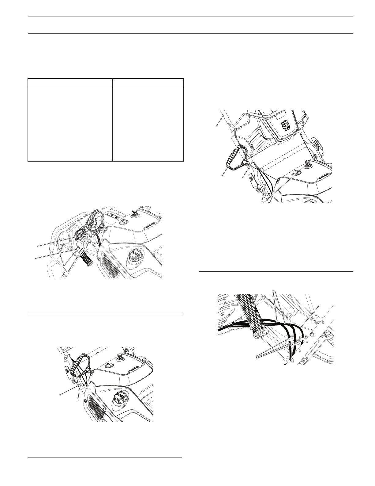
Installing the Handle
1. Remove temporary cable ties holding cables at handle
adjustment holes (Figure 2).
2. Release handle adjustment levers on both sides.
1
4. Pull up and push down slightly on the handle to verify
handle is locked into place (Figure 4).
NOTE: If handle feels unsecure with the adjustment
levers closed, tighten adjustment handle nuts until the
handle feels secure.
5. Remove the cardboard from recoil start handle and
feed the recoil rope through the rope guide.
6. Snap two rotator cables and one wiring harness into
the three cable clips (Figure 5).
1
2
1. Handle
2. Recoil handle
3. Rope guide
4. Adjustment lever nut
3
4
2
Figure 2
1. Cable ties
2. Adjustment lever
3. Lift operator handle up to the desired height, and close
adjustment lever ensuring the positioning pin on the
lower handle engages one of the three holes on the
upper handle (Figure 3).
2
1
Figure 3
Figure 4
1
2
3
Figure 5
1. Rotator cable
2. Wiring harness
3. Cable clip
1. Positioning pin
2. Upper handle adjustment hole
5

ASSEMBLY
Installing the Discharge Chute
1. Install the chute deflector to the discharge chute using
bolts and, washer, nut, deflector knob and cap plunger
(Figure 6).
2. Install the discharge chute to the chute base using
three screws and nuts.
8
7
4
510
3
1
9
6
3
2
2
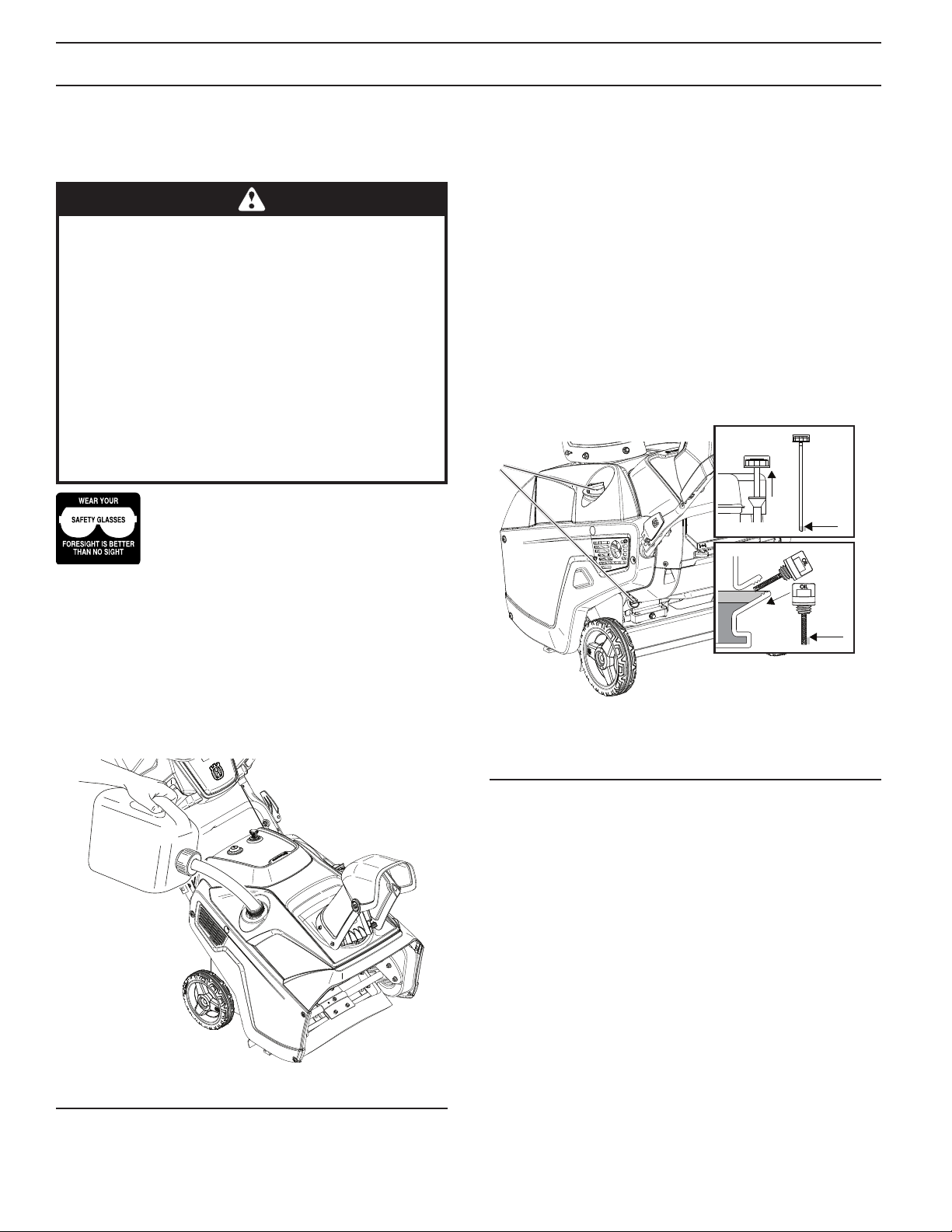
Filling the Engine with Oil
ENGINE
See engine manual.
LUBRICATION
NOTE: Although multi-viscosity oils (5W30, 10W30 etc.)
improve starting in cold weather, these multi-viscosity oils
will result in increased oil consumption when used above
32°F. Check your engine oil level more frequently to avoid
possible engine damage from running low on oil.
Change the oil after every 25 hours of operation or at least
once a year if the snow thrower is not used for 25 hours
in one year.
Check the crankcase oil level before starting the engine
and after each five (5) hours of continuous use. Tighten oil
fill cap / dipstick securely each time you check the oil level.
1. Move the snowthrower to a level surface.
2. Clean around the dipstick (Figure 7).
NOTE: Dipstick location may vary depending on engine
type.
3. Remove either side mounted filler cap dipstick or high
oil fill dipstick and wipe it clean.
Figure 6
1. Deflector
2. Carriage bolts
3. Flange nuts 5/16-18
4. Washer
5. Knob
6. Discharge chute
7. Carriage bolt
8. Shoulder bolt
9. Flange nuts 1/4-20
10. Cap Plunger
IMPORTANT: Do not overtighten the flange nuts;
otherwise you may damage the discharge chute.
1
Fill if oil
is below
“Add”
on the
GLSVWLFN
Fill if oil is
below letter
“L” on the
¿OOHUFDS
Figure 7
1. Oil filler cap/dipstick
4. Insert the dipstick into the filler neck and turn clockwise
until fully seated. Then remove the dipstick by turning
it counter-clockwise.
5. Fill oil to "FULL" on dipstick with the recommended oil.
6. Securely screw in the oil filler cap/dipstick.
6
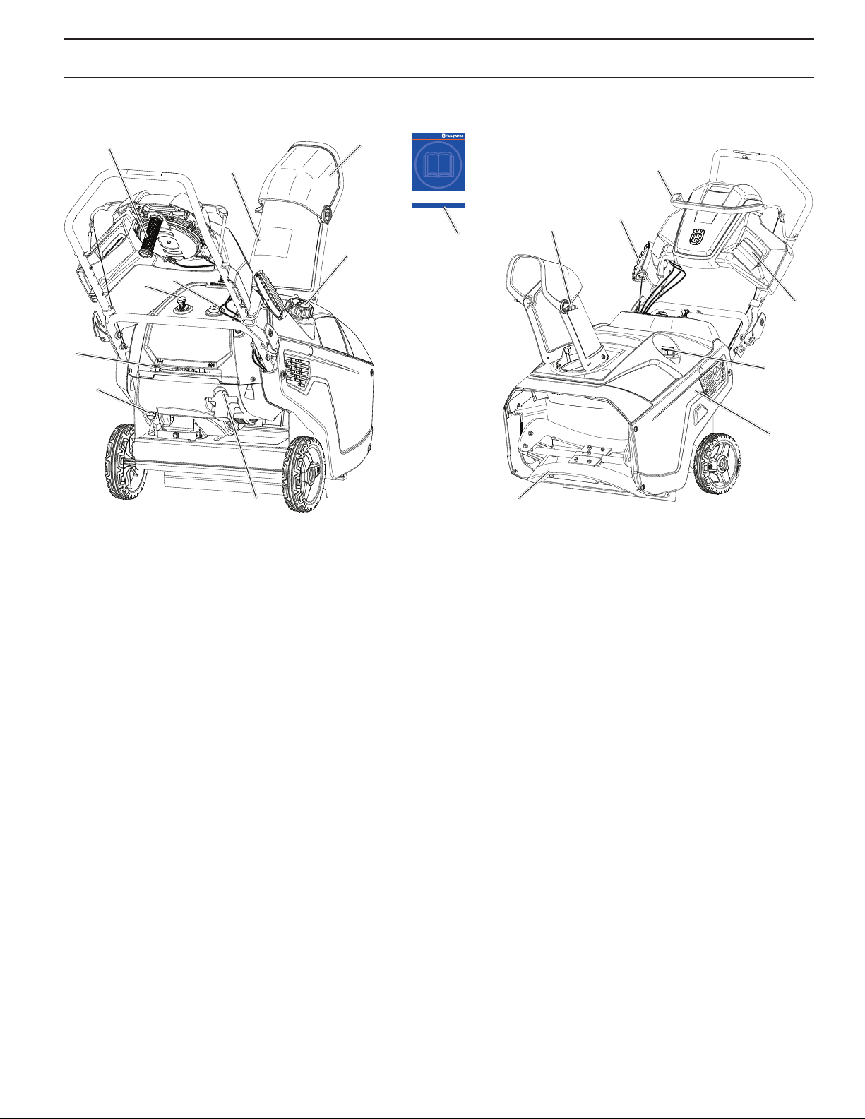
Product Overview
PRODUCT OVERVIEW
8
6, *7
10
2
1
16
3
4
9
5
17
15
12
11
13
*7
14
Figure 8
1. Discharge chute
2. Chute deflector
3. Fuel tank cap
4. Primer
5. Electric-start button
(if equipped)
6. Oil drain plug
7. Oil fill cap/dipstick
8. Choke lever
* Dipstick location may vary depending on engine type.
9. Ignition key
10. Chute rotator handle
11. Recoil start handle
12. Control bar
13. Lights
14. Drive side cover
15. Auger blade
16. Deflector knob
17. Owner's Manual
7
OPERATION
Operation
NOTE: Determine the left and right sides of the machine
from the normal operating position.
• Gasoline is extremely flammable and explosive.
A fire or explosion from gasoline can burn you
and others.
• To prevent a static charge from igniting the gasoline, place the container and/or snowthrower on
the ground before filling, not in a vehicle or on
an object.
• Fill the tank outdoors when the engine is cold.
Wipe up spills.
• Do not handle gasoline when smoking or around
an open flame or sparks.
• Store gasoline in an approved fuel container, out
of the reach of children.
• Do not tip the snowthrower with fuel in the fuel
tank.
The operation of any snow thrower can result
in foreign objects thrown into the eyes, which
can result in severe eye damage. Always wear
safety glasses or eye shields while operating
your snow thrower or performing any ad just ments or repairs. We recommend standard safe ty glasses
or a wide vision safety mask worn over spectacles.
IMPORTANT: Know how to operate all controls before
adding fuel or attempting to start the engine.
IMPORTANT: Do not use E85 blended fuels. This engine
is not E20/E30/E85 compatible. Alternative fuels with
high alcohol content can cause hard starting, poor engine
performance, and may cause internal engine damage.
NOTE: For best results, purchase only the quantity of
gasoline that you expect to use in 30 days. Otherwise,
you may add fuel stabilizer to newly purchased gasoline
to keep it fresh for up to 6 months.
Checking the Engine Oil Level
1. Move the snowthrower to a level surface.
2. Clean around the dipstick (Figure 9).
NOTE: Dipstick location may vary depending on engine
type.
3. Remove either side mounted filler cap dipstick or high
oil fill dipstick and wipe it clean.
1
Fill if oil
is below
“Add”
on the
GLSVWLFN
Fill if oil is
below letter
“L” on the
¿OOHUFDS
Filling the Fuel Tank
Fill the fuel tank with fresh, unleaded gasoline (minimum
87 AKI octane rating) (Figure 8).
Figure 8
IMPORTANT: Do not add oil to the gasoline.
Figure 9
1. Oil filler cap/dipstick
4. Insert the dipstick into the filler neck and turn clockwise
until fully seated. Then remove the dipstick by turning
it counter-clockwise.
5. Fill oil to "FULL" on dipstick with the recommended oil.
6. Securely screw in the oil filler cap/dipstick.
NOTE: Running the engine with a low oil level can cause
engine damage. Always check the engine oil before start up.
NOTE: Running the engine with too much oil may cause
engine damage and excess smoke in the exhaust. Always
check the engine oil level before start up.
8

OPERATION
Starting the Engine
1. Push key in (Figure 10).
2. Move choke lever to left position.
3. Firmly push in the primer 2 times with your thumb,
holding the primer in a for a second before releasing
it each time.
NOTE: Remove your glove when you push in the primer
so that air cannot escape from the primer hole.
IMPORTANT: It may not be necessary to use the primer
or the choke if the engine has been running and is hot.
Excessive priming may flood the engine and prevent it
from starting.
3
1
2
1
Figure 12
1. Electric start button
NOTE: Use an extension cord recommended for outdoor
use that is not longer than 50 feet (15 m).
Figure 10
1. Key
2. Choke lever
3. Primer
4. Pull the recoil starter (Figure 11) or if your snow thrower
is equipped with an electric starter, connect an extension cord to the snow thrower and plug the other end
into a three-hole grounded 110 volt A.C. receptacle
and push the electric-start button (Figure 12).
1
The electrical cord can become damaged, causing
a shock or fire.
Thoroughly inspect the electrical cord before plug-
ging it into a power source. If the cord is damaged,
do not use it to start the snowthrower. Replace or
repair the damaged cord immediately. Contact an
Authorized Service Dealer for assistance.
IMPORTANT: Run the electric starter no more than 10
times at intervals of 5 seconds on, then 5 seconds off.
Running the electric starter extensively can overheat and
damage it. If the engine does not start after this series of
attempts, wait at least 40 minutes to allow the starter to
cool before attempting to start it again. If the engine does
not start after the second series of attempts, take the
snowthrower to an Authorized Service Dealer for service.
NOTE: If you pull the recoil handle and feel no resistance,
the starter may be frozen. Thaw out the starter before
attempting to start the snowthrower.
5. While the engine is running, move the choke lever
slowly to the right position.
6. Unplug the extension cord from the power source and
the snowthrower (Figure 12).
Unplug the power cord whenever you are not start-
ing the snowthrower.
Figure 11
1. Recoil start handle
9

OPERATION
Engaging the Auger Blades
1. To engage the auger blades, hold the control bar against
the handle (Figure 13).
1
1
2
Figure 15
1. Rub Area 2. Wear Areas
Figure 13
1. Control bar
Disengaging the Auger Blades
1. To disengage the auger blades, release the control bar
(Figure 14).
1
Figure 14
1. Control bar
Stopping the Engine
1. To stop the engine, pull key out (Figure 16).
1
1. Key
Figure 16
Adjusting the Discharge Chute and
Chute Deflector
1. To adjust the discharge chute, rotate chute handle left
or right to desired position (Figure 17).
IMPORTANT: During initial operation there may be wear
between the auger blades and the scraper bar. Maximum
performance, both snow throwing and driving, occurs
when there is zero clearance between these two parts
(Figure 15).
During initial break-in period of the auger blades it
is normal for the auger blades to build up excessive
heat if not operated in the snow.
Do not operate without snow or water for lubricating
the auger blades. This will cause excessive heat
build up in the auger blades which could cause
damage to the auger blades and scraper bar.
1
1. Chute rotator handle
Figure 17
10

OPERATION
2. To raise or lower the angle of the chute deflector, loosen
both chute deflector knobs on the chute deflector and
move the chute deflector up or down to desired position
and retighten knobs (Figure 18).
1
2
1. Chute deflector
2. Chute deflector knobs
Figure 18
Clearing a Clogged Discharge
Chute
Hand contact with the rotating auger blades inside
the discharge chute is the most common cause
of injury associated with snow throwers. Never
use your hand to clean out the discharge chute.
Preventing Freeze-up After Use
• Let the engine run for a few minutes to prevent moving
parts from freezing. Stop the engine, wait for all moving parts to stop, and remove ice and snow from the
snowthrower.
• Clean off any snow and ice from the base of the chute.
• Rotate the discharge chute left and right to free it from
any ice buildup.
• With the ignition key in the Off position, pull the recoil
starter handle several times or connect the electrical
cord to a power source and the snowthrower and push
the electric start button once to prevent the recoil starter
and/or the electric starter from freezing up.
• In snowy and cold conditions, some controls and moving parts may freeze. Do not use excessive force when
trying to operate frozen controls. If you have difficulty
operating any control or part, start the engine and let
it run for a few minutes.
Operating Tips
The auger blades can throw stones, toys, and other
foreign objects and cause serious personal injury
to the operator or to bystanders.
• Keep the area to be cleared free of all objects that
the auger blades could pick up and throw.
• Keep all children and pets away from the area of
operation.
• Do not operate snow thrower if weather conditions
im pair visibility. Throwing snow dur ing a heavy,
windy snowstorm can blind you and be hazardous to the safe operation of the snow thrower.
To clear the chute:
1. SHUT THE ENGINE OFF!
2. Wait 10 seconds to be sure the auger blades have
stopped rotating.
3. Always use a clearing tool at least 15 inches long, not
your hands (Figure 19).
Figure 19
• The best time to remove snow is the early morning.
At this time the snow is usually dry and has not been
exposed to the direct sun and warming tem per a tures.
• Slightly overlap each successive path to ensure all
snow will be removed.
• Throw snow downwind whenever possible.
• For extremely heavy snow, re duce the width of snow
removal by over lap ping previous path and moving
slowly.
• Keep engine clean and clear of snow during use. This
will help air flow and extend engine life.
• After snow-throwing is completed, allow engine to run
for a few minutes to melt snow and ice off the engine.
• Clean the entire snow thrower thoroughly after each
use and wipe dry so it is ready for next use.
• Spraying off unit with a hose is NOT recommended.
11

MAINTENANCE
Maintenance
NOTE: Determine the left and right sides of the machine from the normal operating position.
Check for Loose Fasteners
Clean / Inspect Snow Thrower
Clean / Replace V-Belts
Check / Replace Auger Blades and Scraper Bar
Check Fuel Lines and Electrical Wires
Check Engine Oil Level
Change Engine Oil
Inspect Muffler
Check / Replace Spark Plug
Empty Fuel Tank
Adjusting the Control Cable
CHECKING THE CONTROL CABLE
1. Release the control bar to remove the slack in the
control cable (Figure 20).
1
Figure 20
1. Control bar
NOTE: You may need to adjust the control cable from
position 1 (default) to position 2 if you notice belt slip
when the control bar is engaged.
NOTE: If the control cable is adjusted to position 2,
ensure that the auger stops properly when the control bar
is released
ADJUSTING THE CONTROL CABLE
1. With the control bar disengaged, unhook and move
the control cable to the highest position. (Figure 21).
1
2
Position 2
3
IMPORTANT: The control cable must contain some slack
when you disengage the control bar for the auger blades
to stop properly.
12
1. Control bar
2. Adjuster link
3. Cable positions
Figure 21
Position 1:
Default position
(Lower Hole as
shown in illustration)

MAINTENANCE
Inspecting the Auger Blades/
Scraper Bar
Before each session, inspect the auger blades for wear.
When an auger blade edge or the scraper bar has worn
down have an Authorized Service Dealer replace the
auger blades and the scraper bar (Figure 22).
NOTE: Auger blades and scraper bar are wear items and
may have to be replaced after extended use.
1
2
Figure 22
1. Auger blades
2. Scraper bar
Changing the Engine Oil
Run the engine a few minutes before changing the
oil to warm it. Warm oil flows better and carries more
contaminants.
The engine oil will be hot. Avoid skin contact
with the used engine oil.
1. Move snowthrower to a level surface.
2. Run snowthrower until all fuel has been depleted.
3. Remove ignition key.
4. Place an oil drain pan under the oil drain plug, remove
the oil drain plug, and tip the snowthrower backward
and drain the used oil in the oil drain pan (Figure 23).
5. After draining the used oil, return the snowthrower to
the operating position.
6. Screw in the oil fill cap/dipstick (1) and hand tighten it
securely.
NOTE: Dipstick location may vary depending on engine
type.
1
Figure 24
1. Oil fill cap/dipstick
7. Clean around the oil filler cap/dipstick (Figure 24).
8. Unscrew the oil fill cap/dipstick and remove it
(Figure 25).
9. With the snowthrower in the operating position, carefully pour oil into the oil fill hole until "Full" on the fill
cap/dipstick line (Figure 25).
Max fill: 18 oz. (0.5 l), type: automotive detergent oil
with an API service classification of SJ, SL, or higher.
Fill if oil
is below
“Add”
on the
GLSVWLFN
1
1. Oil drain plug
Figure 23
Figure 25
10. Screw in the oil fill cap/dipstick and hand tighten it
securely.
11. Wipe up any spilled oil.
12. Dispose of the used oil properly at a local recycling
center.
13
Fill if oil is
below letter
“L” on the
¿OOHUFDS

MAINTENANCE
Servicing the Spark Plug
Use a NGK BPR6ES, Champion RN9YC, or BOSCH
WR6DC spark plug or equivalent.
1. Move snow thrower to a level surface.
2. Run snow thrower until all fuel has been depleted.
3. Wait until engine is cool.
4. Rotate the discharge chute so that it faces forward.
5. Remove the discharge chute by removing the three
carriage bolts and three flange nuts (Figure 26).
1
3
3
2
2
8. Unsnap top cover by firmly pulling upwards at the
rear section of the cover disengaging the three clips
(Figure 28).
9. Shift top cover until fuel tank is clear of the rear upper
cover and set top cover to the side of the unit.
10. Temporarily reinstall oil fill cap to prevent foreign object
from entering the engine.
11. Remove 2 screws in the side cover and rear covers
on both sides.
2
1
3
4
33
Figure 26
1. Discharge chute 3. Flange nuts
2. Carriage bolts
6. Remove two screws in plenum that hold top cover
(Figure 27).
7. Remove the oil fill cap.
2
3
1
4
Figure 27
Figure 28
1. Top cover 3. Screw
2. Clips 4. Rear upper cover
12. Unplug electrical wires on back of ignition switch
(Figure 29).
13. Pull tube off the back of the primer bulb.
4
2
24
1
Figure 29
1. Electrical wires 3. Tube
2. Ignition switch 4. Primer bulb
3
1. Screw 3. Oil fill cap
2. Plenum 4. Top cover
14. Lift rear upper cover and lay it to the side of the unit.
IMPORTANT: The recoil rope will still be attached to the
upper cover.
14

MAINTENANCE
15. Disconnect the spark plug wire from the spark plug
(Figure 30).
16. Clean around the spark plug.
17. Remove the spark plug from the cylinder head.
1
Figure 30
1. Spark plug wire
IMPORTANT: Replace a cracked, fouled, or dirty spark
plug. Do not clean the electrodes because grit entering
the cylinder can damage the engine.
19. Install the spark plug and torque it to 20–22 ft-lb
(27–30 N-m).
20. Connect the spark plug wire to the spark plug
(Figure 30).
21. Reattach primer bulb tube to primer bulb and electrical wires on back ignition switch of rear upper cover
(Figure 29).
22. Set rear upper cover in place so the two screw holes
line up with the rear lower cover and side covers
(Figure 32).
23. Reattach two screws through the rear covers and into
the clip on the side cover (Figure 27).
18. Set the gap on the plug to 0.030 inch (0.76 mm)
(Figure 31).
0.030 inch
(0.76 mm)
Figure 31
Figure 32
24. Remove top oil fill cap.
25. Set top cover in place and snap three top cover clips
into the rear upper cover (Figure 28).
26. Reinstall top oil fill cap.
27. Reinstall two screws in the side covers that attach to
the clips on the top cover.
28. Reinstall two screws in the plenum that attach to the
top cover (Figure 27).
29. Reinstall discharge chute with the hardware removed
in step 5.
15

MAINTENANCE
Replacing the Auger V-Belt
If auger v-belt becomes worn, oil-soaked, excessively
cracked, frayed, or otherwise damaged, replace the belt.
1. Remove the drive side cover by removing the six screws
as shown in (Figure 33).
5
4
3
Figure 33
6
7
2
1
2
4. Install the new auger v-belt and drive pulley, routing it
as shown in (Figure 34).
NOTE: Route the new auger v-belt first around the engine
pulley, then the idler pulley, and finally around the drive
pulley while pressing down on the front of the idler arm.
(Figure 33).
5. Install the drive side cover with the screws removed in
step 1.
NOTE: Ensure belt keeper on the plastic side panel
engages between belt and frame before bolting down.
1
2
3
1. Drive side cover
2. Screw
3. Drive pulley
4. Idler arm
2. Remove drive pulley from the auger shaft.
NOTE: Nut is welded to drive pulley and has left handed
threads.
3. Remove the auger v-belt from the drive pulley.
5. Idler pulley
6. Engine pulley
7. Auger V-Belt
4
Figure 34
1. Idler arm
2. Idler pulley
3. Engine pulley
4. Drive pulley
NOTE: Ensure that the auger v-belt is properly adjusted
and operating; refer to Checking the Control Cable and
Adjusting the Control Cable in the Maintenance section
of this manual.
16

STORAGE
Storage
STORING THE SNOWTHROWER
Immediately prepare your snow thrower for storage at
the end of the season or if the unit will not be used for 30
days or more.
WARNING: Never store the snow thrower with
gaso line in the tank in side a build ing where fumes
may reach an open flame, spark or pilot light as
on a fur nace, water heater, clothes dryer or gas
ap pli ance. Allow the engine to cool be fore storing
in any enclosure.
SNOW THROWER
When snow thrower is to be stored for a period of time,
clean it thor oughly, re move all dirt, grease, leaves, etc.
Store in a clean, dry area.
1. Clean entire snow thrower after each use.
2. Inspect and replace belts, if necessary (See “Replaceing the Drive Belt” sec tion of this manual).
3. Be sure that all nuts, bolts, screws, and pins are securely
fas tened. Inspect moving parts for damage, breakage
and wear. Replace if nec es sary.
ENGINE OIL
Drain oil (with engine warm) and replace with clean engine
oil. (See “Changing the Engine Oil” section of this man ual).
CYLINDER
1. Remove spark plug.
2. Pour one ounce (29 ml) of oil through spark plug hole
into cylinder.
3. Pull recoil starter handle slowly a few times to dis trib ute
oil.
OTHER
• Remove safety ignition key; store it in a safe place.
• Do not store gasoline from one season to another.
• Replace your gasoline can if your can starts to rust.
Rust and/or dirt in your gasoline will cause problems.
• If possible, store your snow thrower indoors and cover
it to protect it from dust and dirt.
• Cover your snow thrower with a suitable pro tec tive
cover that does not retain moisture. Do not use plastic.
Plastic cannot breathe, which allows con den sa tion to
form and will cause your snow thrower to rust.
IMPORTANT: Never cover snow thrower while engine/
exhaust area is still warm.
FUEL SYS TEM
IMPORTANT: It is important to prevent gum deposits from
forming in essential fuel system parts such as carburetor,
fuel hose, or tank during storage. Also, alcohol blended
fuels can attract moisture which leads to separation and
formation of acids during storage. Acidic gas can damage
the fuel system of an engine while in storage.
• Empty the fuel tank by starting the engine and letting
it run until the fuel lines and car bu re tor are empty.
• Never use engine or carburetor cleaner prod ucts in
the fuel tank or permanent damage may occur.
• Use fresh fuel next season.
NOTE: Fuel stabilizer is an acceptable alternative in min i miz ing the formation of fuel gum deposits during stor age.
Add stabilizer to gasoline in fuel tank or storage container.
Always follow the mix ratio found on stabilizer container.
Run engine at least 10 min utes after adding stabilizer to
allow the stabilizer to reach the carburetor. Do not empty
the gas tank and carburetor if using fuel stabilizer.
17

TROUBLESHOOTING
Troubleshooting
See appropriate section in manual unless directed to a service center/department.
PROBLEM CAUSE CORRECTION
Does not start 1. Safety ignition key is not inserted. 1. Insert safety ignition key.
2. Out of fuel. 2. Fill fuel tank with fresh, clean gasoline.
3. ON/OFF switch is OFF. 3. Move ON/OFF switch to ON position.
4. Choke in OFF position. 4. Move to FULL position.
5. Primer not depressed. 5. Prime as instructed in the Operation section of this manual.
6. Engine is flooded. 6. Wait a few minutes before restarting, DO NOT prime.
7. Spark plug wire is disconnected. 7. Connect wire to spark plug.
8. Bad spark plug. 8. Replace spark plug.
9. Stale fuel. 9. Empty fuel tank & carburetor, refill with fresh, clean gasoline.
10. Water in fuel. 10. Empty fuel tank & carburetor, refill with fresh, clean gasoline.
11. Vapor locked fuel line. 11. Ensure all the fuel line is below the outlet of the fuel tank. Fuel
Loss of power 1. Spark plug wire loose. 1. Reconnect spark plug wire.
2. Throwing too much snow. 2. Reduce speed and width of swath.
3. Fuel tank cap is covered with ice or
snow.
4. Dirty or clogged muffler. 4. Clean or replace muffler.
5. Improper cable length. 5. Adjust cable.
6. Blocked muffler. 6. Clear blockage (ensure engine is cool).
7. Blocked carburetor air intake. 7. Clear blockage (ensure engine is cool).
Engine idles or
runs roughly
Excessive
vibration / Handle
movement
Recoil starter is
hard to pull
Loss of snow
discharge or
slowing of snow
discharge
Lights not On
(If Equipped)
Rotator hard to
move
1. Choke is in FULL position. 1. Move choke to OFF position.
2. Blockage in fuel line. 2. Clean fuel line.
3. Stale fuel. 3. Empty fuel tank & carburetor, refill with fresh, clean gasoline.
4. Water in fuel. 4. Empty fuel tank & carburetor, refill with fresh, clean gasoline.
5. Carburetor is in need of replacing 5. Contact an authorized service center/department.
6. Belt stretch. 6. Replace auger v-belt.
1. Loose parts or damaged augers or
impeller.
2. Handles not positioned correctly. 2. Ensure handles are locked into positioning.
3. Adjustment lever nuts are loose. 3. Tighten nuts until handle feels secure.
1. Frozen recoil starter. 1. See “IF RECOIL STARTER HAS FROZEN” in the Operation
2. Rope is interfering with components. 2. Recoil rope should not be touching any wires or hoses.
1. Worn belt. 1. Adjust drive cable per maintenance procedures.
2. Auger v-belt is off of pulley. 2. Check / reinstall auger v-belt.
3. Auger v-belt is worn. 3. Check / replace auger v-belt.
4. Clogged discharge chute. 4. Clean snow chute.
5. Augers / impeller jammed. 5. Remove debris or foreign object from augers / impeller.
1. Motor not running. 1. Start engine.
2. Loose wire connection. 2. Check wire connections at engine and both lights.
3. LED burnt out. 3. Replace LED light module. (Individual LEDs are not replaceable)
1. Debris in chute rotator mechanism. 1. Clean internal parts of chute rotator mechanism.
2. Cable are kinked or damaged. 2. Ensure cables are not kinked. Replace damaged cables.
line should run continuously down from fuel tank to carburetor.
3. Remove ice and snow on and around fuel tank cap.
1. Tighten all fasteners. Replace damaged parts. If vibration
remains, contact an authorized service center/department.
section of this manual.
18

SERVICE NOTES
19

Consumer Wheeled Products - Limited Warranty
Husqvarna warrants to the original retail purchaser that this product is free from defects in material or workmanship under normal use
and maintenance from the date of retail purchase for the applicable Warranty Period shown on Exhibit A. This Limited Warranty may not be transferred
to any subsequent purchaser of this product. Certain components (e.g., engines and transmissions) are excluded from coverage, and other
limitations apply, as described in this document. Husqvarna will repair or replace at its discretion, any defective product or part covered by the Limited
Warranty, free of charge at any authorized Husqvarna Servicing Dealer/Center using original OEM Husqvarna replacement parts, subject to the
limitations and exclusions described below. Husqvarna does not offer an over-the-counter exchange program.
DISCLAIMERS, LIMITATIONS AND EXCLUSIONS
1. WARRANTY DISCLAIMER. THIS LIMITED WARRANTY IS THE SOLE EXPRESS WARRANTY PROVIDED BY HUSQVARNA AND THERE ARE NO
WARRANTIES WHICH EXTEND BEYOND THE DESCRIPTION ON THE FACE HEREOF, EXCEPT AS MAY BE PROVIDED BY LAW. THIS WARRANTY IS
GIVEN ONLY BY HUSQVARNA, AND MAY BE MODIFIED ONLY BY HUSQVARNA. THIS LIMITED WARRANTY IS THE FINAL EXPRESSION OF OUR
AGREEMENT, AND IS A COMPLETE AND EXCLUSIVE STATEMENT OF THE TERMS OF THAT AGREEMENT. THIS LIMITED WARRANTY GIVES YOU
SPECIFIC LEGAL RIGHTS, AND YOU MAY ALSO HAVE OTHER RIGHTS WHICH VARY BASED ON LOCALITY
2. LIMITED DURATION. ANY WARRANTY THAT MAY BE IMPLIED BY LAW (INCLUDING ANY IMPLIED WARRANTY OF FITNESS FOR A
PARTICULAR PURPOSE OR USE AND IMPLIED WARRANTY OF MERCHANTABILITY) IS LIMITED TO THE DURATION OF THE APPLICABLE
WARRANTY PERIOD UNDER THIS LIMITED WARRANTY. SOME LOCALITIES DO NOT ALLOW LIMITATIONS ON HOW LONG AN IMPLIED
WARRANTY LASTS, SO THE ABOVE LIMITATIONS MAY NOT APPLY TO YOU.
3. EXCLUSIVE REMEDIES. SOME LOCALITIES, INCLUDING THE PROVINCE OF QUEBEC, DO NOT ALLOW THE EXCLUSION OR LIMITATION OF
LIABILITY FOR INJURY TO PERSON OR FOR DAMAGES RESULTING FROM THE FAULT OF THE MANUFACTURER AND/OR THE EXCLUSION OR
LIMITATION OF INCIDENTAL OR CONSEQUENTIAL DAMAGES. AS SUCH, SOME OF THE FOLLOWING LIMITATIONS MAY NOT APPLY TO YOU. THE
ABOVE REMEDIES ARE THE EXCLUSIVE REMEDIES FOR ANY BREACH OF THIS LIMITED WARRANTY. NO OTHER REMEDY, INCLUDING, BUT NOT
LIMITED TO ANY SPECIAL, INCIDENTAL, INDIRECT OR CONSEQUENTIAL DAMAGES, FOR LOST PROFITS, LOST SALES, INJURY TO PERSON OR
PROPERTY, OR ANY OTHER INCIDENTAL OR CONSEQUENTIAL LOSS SHALL BE AVAILABLE, AND ALL SUCH DAMAGES ARE HEREBY
DISCLAIMED.
4. Engines, Transmissions and certain other components are NOT covered. This Limited Warranty does not cover any of the following:
(a) Engines and Attachments.Except where otherwise indicated on Exhibit A, all Engines and Attachments are not covered by this Limited Warranty. In most cases, these
items are NOT manufactured by Husqvarna in which case they may be covered separately by their respective manufacturer's warranties if one is provided and included with
the product at the time of purchase. All such claims must be submitted and sent to the appropriate manufacturer or as otherwise directed in those separate warranties.
Husqvarna is not authorized to handle warranty adjustments or repairs on engines manufactured by Briggs & Stratton, Honda, Kawasaki, or Kohler (with the exception of
models equipped with LCT engines). Husqvarna does not assume any warranty obligation of the other manufacturers' engines under this Limited Warranty.
(b) Transmissions. Except where otherwise indicated on ExhibitA, Transmission / Transaxle (including Drive Systems) are not covered by this Limited Warranty. In most
cases, these items are NOT manufactured by Husqvarna in which case they may be covered separately by their respective manufacturer's warranties if one is provided and
included with the product at the time of purchase. The following transmission / transaxle manufacturers, Dana, Hydro-Gear, Tuff-Torq provide a warranty for the
transmission / transaxle to the ultimate purchaser or to Husqvarna. Husqvarna will assign the transmission / transaxle manufacturer's warranty or any rights thereof to the
original purchaser of the unit. To obtain transmission / transaxle warranty service, first contact the retailer who you purchased the unit from. Should you require assistance
or have any questions concerning transmission / transaxle warranty coverage, contact Husqvarna directly at our website www.husqvarna.com or call 800-487-5951 (US) or
800-805-5523 (Canada) for an authorized Husqvarna service provider. All such claims must be submitted and sent to the appropriate manufacturer or as otherwise directed
in those separate warranties. Husqvarna is not authorized to handle warranty adjustments or repairs on transmissions or transaxles. Husqvarna does not assume any
obligations under this Limited Warranty for the above listed manufacturers (for exceptions - see Exhibit A).
(c) Expendable Parts. This Limited Warranty does not cover general maintenance parts and items ("Expendable Parts"), including without limitation spark plugs, bulbs,
filters, lubricants, starter cords, belts, blades, and blade adapters.
(d) Emissions Control Components. This Limited Warranty does not cover Emissions control equipment and components to the extent regulated by the U.S. Environmental
Protection Agency or similar state, provincial or federal agencies. Such equipment and components are covered by a separate emission control warranty statement supplied
with your new product. Please consult this separate warranty statement for details.
5. Any COMMERCIAL, INSTITUTIONAL, AGRICULTURAL, INDUSTRIAL, INCOME PRODUCING, or RENTAL use will result in either
No Warranty or a Shortened Warranty Period. Depending on the product, there is either NO WARRANTY (whether statutory, contractual or
otherwise) or a reduced warranty if the product is used for commercial, institutional, agricultural, industrial, income producing, or rental purposes and, in
such circumstances, this Limited Warranty is offered instead of and replaces any warranty regime provided for by law. Please refer to Exhibit A.
6. Reconditioned or Refurbished Products have a 30 Day Limited Warranty. Under this Limited Warranty, Certified Factory Reconditioned or
Refurbished products have a 30 Day Limited Warranty for parts and labor for Non-Commercial Use. Products are only reconditioned at the Husqvarna
Factory.
7. Owner's (Your) Responsibilities. To preserve your rights under this Limited Warranty, you must exercise reasonable care and use of the product,
including, following the preventative maintenance, storage, fuel and oil usages as prescribed in the enclosed operator's manual. For example, the
following items are the Owner's responsibility and are not covered by this Limited Warranty:
a. Set-up and pre-delivery service, and engine tune-ups;
b. Adjustments after the first (30) thirty days of purchase and beyond, such as throttle cable, belt guides adjustments; and
c. Preventative maintenance as outlined in the operator's manual.
In addition, you must cease using the product immediately upon any failure or damage. The product should be taken to an authorized Husqvarna
servicing dealer prior to any further use.
8. Damages resulting from normal aging, wear and tear or neglect are NOT covered. The Limited Warranty does not cover damage other than
that resulting from defects in material or workmanship. The following are NOT considered defects in material or workmanship, and therefore are NOT
covered.
20

(a)Ab
rasionto mower decks;
(b) Tires damaged by external punctures;
(c) Natural discoloration of materials due to ultraviolet light;
(d) Damage to cutting equipment by way of contact with, rocks, or other non-approved materials and/or structures;
In addition, this Limited Warranty does not cover damages, malfunctions or failures resulting from abuse or neglect of the product related to or including
any of the following:
(e) Failure to provide or perform required maintenance services as prescribed in the operator's manual;
(f) Abuse, misuse, neglect, modifications, alterations, normal wear, improper servicing, use of unauthorized attachments, Lack of lubrication or
engine failure, due to the use of oils that do not meet Engine manufacturer's specifications;
(g) Use of gasohol, containing methanol (wood alcohol). Gasohol which contains a maximum 10% ethanol (grain alcohol) or 15% MTBE
(methyl/tertiary/butyl/ether) is approved;
(h) Use of ether or any starting fluids;
(i) Pressure cleaning or steam cleaning the product;
(j) Use of spark plugs other than those meeting emission performance requirements listed in the operator's manual;
(k) Tampering with engine speed governor or emission components, or running engines above specified and recommended engine speeds as
listed in your operator's manual;
(l) Operation of the unit with improperly installed/removed or modified cutting shields, guards, or safety devices;
(m) Any removed/damaged air filter, excessive dirt, abrasives, salt water, moisture, corrosion, rust, varnish, stale fuel, or any adverse reaction due
to incorrect storage procedures;
(n) Failures due to improper set up, pre-delivery service or repair service by anyone other than an authorized Husqvarna servicing dealer during
the warranty period;
(o) Dirt contaminated grease or oil, use of incorrect type of greases or oils, failure to comply with recommended greasing intervals, water or
moisture damage, and/or improper storage;
(p) Spray ers pumping or sp raying caustic or flammable materials, lack of or broken strainers; or
(q) Continued use of product, after initial operational problem or failure occurs.
9. Reinforced Stamped (Armor Protected) 10 Year Limited & Fabricated Limited Lifetime, Deck Warranties. These Limited Warranties are for
the deck shell only
wheels
mechanical components/parts such as belts, pulleys, spindle housings, bearings, blades, rods, height adjusters, caster/anti scalp
are NOT covered. The Limited Lifetime Warranty does not cover damage other than that resulting from defects in material or
workmanship. The following are NOT considered defects in material or workmanship, and therefore are NOT covered:
(a) Abrasion to mower decks, including sand wear;
(b) Damage to cutting equipment by way of contact with, rocks, or other non-approved materials and/or structures;
(c) Rust and corrosion; and
(d) Natural discoloration of paint or other materials due to ultraviolet light.
HOW TO OBTAIN SERVICE
10. Authorized Husqvarna Servicing Dealer/Center. In order to obtain warranty coverage it is your responsibility (at your expense) to deliver or ship
your Husqvarna unit to an authorized Husqvarna Servicing Dealer/Center and arrange for pick-up or return of your unit after the repairs have been made.
If you do not know the location of your nearest authorized Husqvarna Servicing Dealer, call Husqvarna, at 1-800-487-5951 during the hours of 8:00 AM
to 8:00 PM Eastern Standard Time, or visit www.husqvarna.com. Should you require assistance or have questions concerning this Limited Warranty, you
may contact us at 800-487-5951 (US) or 800-805-5523 (Canada) during the hours of 8:00 AM to 8:00 PM Eastern Standard Time or contact us through
the web at www.husqvarna.com.
11. Documentation Required. You must maintain and present Proof of purchase (including date, product model and, if applicable, engine serial
number) to an authorized Husqvarna Servicing Dealer for warranty service under this Limited Warranty. Proof of purchase rests solely with you.
Husqvarna encourages you to register your product online at www.usa.husqvarna.com (US & Canada) to help ensure, among other things, that you can
be notified of important product information. However, registering your product is not a condition of warranty service.
Husqvarna Professional Products, NA, Inc.
9335 Harris Corners Parkway, Suite 500, Charlotte, NC28269
575 49 43-01 W 2012 IR
21

Consumer Wheeled Limited Warranty Chart 2012 Exhibit A
)
y
y
y
y
y
y
y
y
y
y
y
y
y
y
y
y
y
y
y
p
Consumer (personal,
household use only)
Product/Com
Riding Lawn Tractors:
Frame, Chassis, Front Axle 5 Years No Warranty No Warranty
Engine*
Transmission (if made by Husqvarna/Peerless)
Transmission (if third party)** ** ** **
XLS Models only - stamped deck shell. Armor
Protected Limited Warranty
Fabricated Deck shell. Limited Lifetime Warranty
Battery
Other Non-Expendable Components 3 Years No Warranty No Warranty
Residential Zero Turn Mowers ( RZ Only )
Engine*
Transmission ** ** No Warranty No Warranty
RZ4623 (967009801 & 967009802)
RZ5426 (967003601 & 967003602) - stamped deck
shell. Armor Protected Limited Warranty
Fabricated Deck shell. Limited Lifetime Warranty
Battery
Other Non-Expendable Components 3 Years No Warranty No Warranty
Residential Zero Turn Mowers ( MZ & EZ )
Engine*
Transmission ** ** ** **
MZ5424S & MZ5425S (967003901 & 25021) stamped deck shell. Armor Protected Limited
Warranty
onent
* * *
3 Years No Warrant
10 Years No Warranty No Warranty
*** No Warrant
1 Year Pro-rated No Warrant
* * *
10 Years No Warranty No Warranty
*** No Warrant
1 Year Pro-rated No Warrant
* * *
10 Years No Warranty No Warranty
Commercial (any commercial,
professional, institutional, agricultural, or
income producing use, other than
Rental Use
Rental (any
rental usage)
No Warrant
No Warrant
No Warrant
No Warrant
No Warrant
Fabricated Deck shell. Limited Lifetime Warranty
Battery
Other Non-Expendable Components 3 Years 1 Year No Warranty
LE475 Edger, Tillers, Snow Throwers
Engine*
Other Non-Expendable Components 2 Years 90 days 90 days
Tiller Tines
Walk Behind Mowers, High Wheel Trimmer
Engine*
Battery
Other Non-Expendable Components 3 Years No Warranty No Warranty
Hovering Trimmers
Engine*
Other Non-Expendable Components 2 Years 1 Year 90 days
Front Mounted Deck Riders
Engine*
Transmission 2 Years No Warranty No Warranty
Other Non-Expendable Components 2 Years No Warranty No Warranty
Cultivators
Battery 1 Year Pro-rated No Warranty No Warranty
Other Non-Expendable Components 2 Years No Warranty No Warranty
Pressure Washers
Model 5525PW:
Engine*
Pump 2 Years No Warranty No Warranty
Other Non-Expendable Components 2 Years No Warranty No Warranty
All other Pressure Washers (6027PW, 9032PW, 1340PW)
Engine*
Pump 2 Years 2 Years No Warranty
Other Non-Expendable Components 2 Years 2 Years No Warranty
*** No Warrant
1 Year Pro-rated No Warrant
* * *
***
* * *
1 Year Pro-rated No Warrant
* * *
* * *
* * *
* * *
No Warrant
No Warrant
No Warrant
No Warrant
No Warrant
Generators
Engine*
Other Non-Expendable Components*
Spreaders
*2 Years (2nd Year Parts
* * *
Only) *2 Years-1365GN (2nd Year Parts Only)
22
No Warrant

Consumer Wheeled Limited Warranty Chart 2012 Exhibit A
)
p
Consumer (personal,
household use only)
Spreader 1 Year 1 Year 1 Year
Product/Com
Robotic Mowers
Robotic Mower 2 Years 90 days 90 days
Battery 1 Year 1 Year 1 Year
Parts & Accessories (if purchased)
Accessories (e.g., grass catcher, bumper guard
accessories, etc.
Parts (e.g., belts, blades, etc.) 30 days No Warranty No Warranty
Parts & Accessories (if replaced in Warranty Service)
Replacement parts and/or accessories provided
under this Limited Warranty are warranted only for
the BALANCE of the warranty period applicable to
the part or accessory that was replaced.
* See Separate Engine Manufacturer's or Manufacturer's warranty. LCT Engines on specific Snow Throwers & Tillers, warranty through
Husqvarna.
** See reference 1 (b) of the warranty statement.
RZ - Two (2) Year Consumer warranty, parts & labor, with Hydro-Gear Distributor network.
EZ - One (1) Year Commercial warranty, parts & labor, with Husqvarna.
Two (2) Year Consumer warranty, parts & labor, with Hydro-Gear Distributor network.
MZ - Two (2) Year Commercial warranty, parts & labor, with Hydro-Gear Distributor network.
*** "Limited Lifetime Warranty" on Tiller tines and Fabricated Deck shell is for the life of the product or 7 (seven) years after the last date of the
complete unit's final production, whichever comes first. Deck Shell replacement will be limited to a maximum of two (2) decks within the Limited
Lifetime Warranty.
onent
1 Year No Warranty No Warranty
See to left See to left See to left
Consumer Commercial Rental
Commercial (any commercial,
professional, institutional, agricultural, or
income producing use, other than
Rental Use
Rental (any
rental usage)
Armor Protected Stamped Deck Shell Example Below Fabricated Deck Shell Example Below
Armor Protected
Stamped Deck Shell
Reinforced area
Stamped Deck Shell below, NOT reinforced
No reinforced area
23

07/06/2012 TH
 Loading...