

Page 1

Operator’s manual
Soff-Cut 2500
Pleasereadtheoperator’smanualcarefullyandmakesureyou
understandtheinstructionsbeforeusingthemachine.
US
Page 2
CONTENTS
UNPACKING
Content Page
Table of contents ………………………….. 2
Unpacking .................................................. 2
Transporting ............................................... 2
Sound Data ................................................ 2
Introduction, personal safety ...................... 3
Registration of the product ………………… 4
General safety message ............................ 4
Safety warnings ......................................... 5
Excel series blades ................................... 6
Blade and skid plate installation ................ 6
What is what? ............................................ 7
Operating instructions ............................... 8-9
Fuel and fuel safety warnings …….…….... 10
Recommended fuels ................................. 10
Recommended oils …….......……….…..… 10
Engine and transmission maintenance ..... 11
Other maintenance ………………….…….. 12
Sawing contraction joints …………....….… 13
Your 2500 saw has been shipped from the factory thoroughly
inspected. Only minimal assembly is required to start using
the saw. Remove the saw from the container using proper lifting techniques. Discard or recycle the packing material per
your regional laws. In your container will be the 2500 saw,
diamond blade, skid plate, blade shaft wrench, spark plug
wrench, an owner’s manual, an engine owner’s manual, a part
list, a warranty card, a joint protector sample pack and a ramp
for unloading the saw. Connect the battery cables and turn the
key switch to the “ON” or “1” position on the instrument panel.
Press the rocker switch on the instrument panel to raise the
saw. Place the unloading ramp at the edge of the container
and roll the saw out of the container. Lower the saw and turn
the key switch to the “OFF” or “0” position.
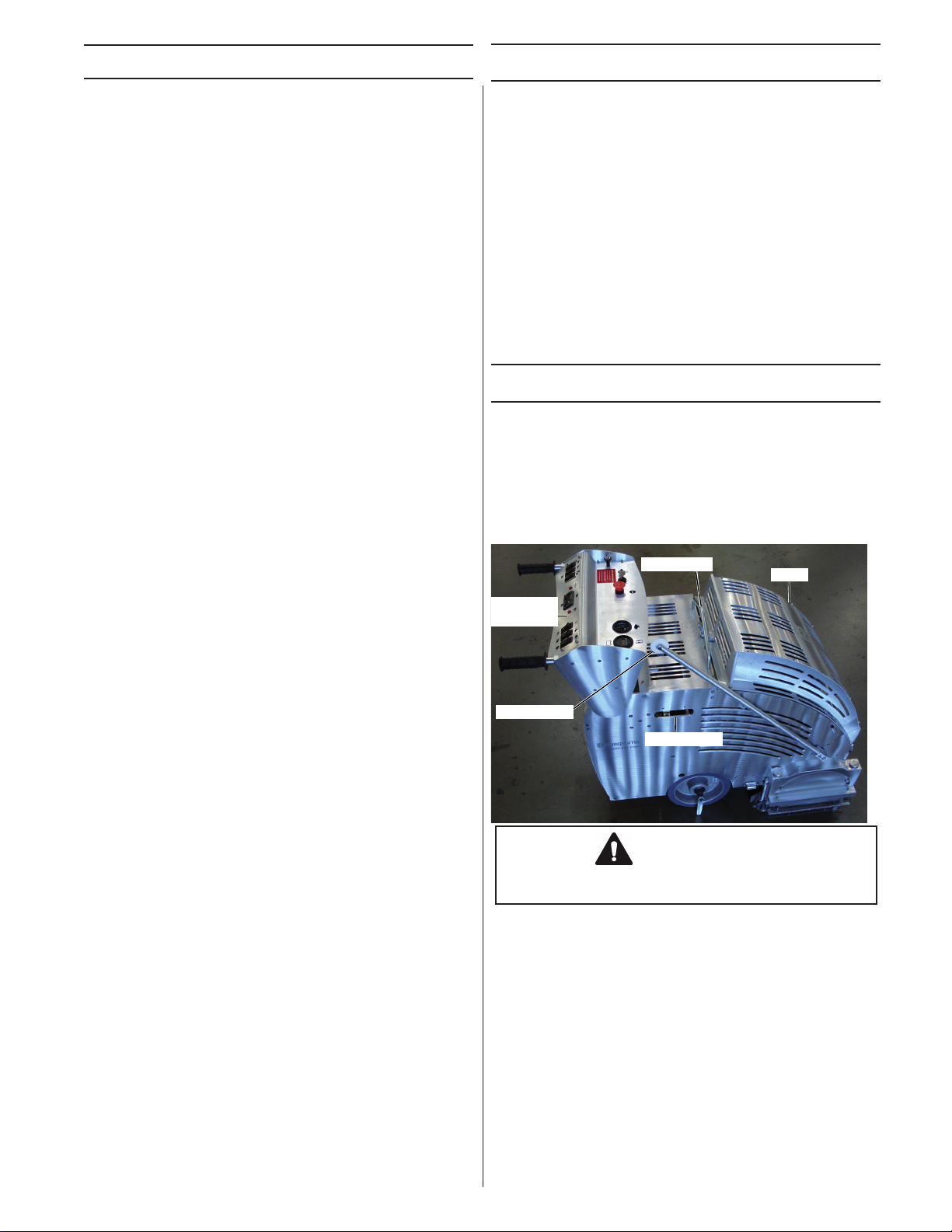
TRANSPORTING
The 2500 saw weights approximately 348 pounds (158 kilograms) when ready to use . Use safe lifting practices when
handling the saw. Always remove the diamond blade when
transporting the saw. Always transport the saw with a skid
plate installed. Retract the guide arm. The saw can be lifted
from the center lifting frame. Always store and transport the
saw in a completely lowered position and secured from moving.
Lifting point
Hood
Maximizing the Soff-Cut system .......…..... 14
Troubleshooting ......................................... 15
Technical specifications ............................. 16
Conformity certificates ............................... 16
Warranty .................................................... 17
Instrument
panel
Front guide
Lifting point
CAUTION
Only use the center lifting frame
when lifting the 2500.
2
Page 3

INTRODUCTION
The 2500 is designed as a medium to heavy duty commercial, industrial, and paving Ultra Early
Entry concrete saw. The patented Soff-Cut Ultra Early Entry dry cutting system controls random cracking of
concrete through the early timing of the saw cutting usually within one to two hours after nishing process
is completed. The patented low noise and low dust blade block and skid plate technology in conjunction
with the Husqvarna blades allows for Ultra Early Entry sawing the same day while minimizing chipping and
spalling. The saw is a self-propelled style with electric switch controls for all functions and electric start.
Common sense:
The focus of this manual is HOW to operate and service the equipment safely.
It is not possible to cover every conceivable situation you can face when using this equipment. Therefore use this
product only in a manner described in this manual. Operation or handling the machine in any other manner can
lead to serious injury or death.
If a situation is not described in this manual it should be considered dangerous - and not be done.
If you are unfamiliar with this product make sure that you carefully understand how it functions and practice all
operations and handling before putting the machine to use. Familiarize yourself in the presence of an experienced
operator. Avoid all situations that are beyond your capability.
If you still feel uncertain about the operating procedures after reading these instructions DO NOT operate the
machine until you have consulted an experienced operator.
If you have further questions you can contact the closest Husqvarna Construction Products location by writing or
calling, see information below. You can also nd the closest location by searching the internet at;
www.husqvarnacp.com . Husqvarna Construction Products will willingly be of service and provide you with advice
as well as help you to use your product both efciently and safely.
Additional manuals are available at NO CHARGE and can also be obtained on the internet site.
Toll Free no: 800 776 3328 (USA & Canada)
Husqvarna Construction Products
265 Radio Road
Corona, California 92879
USA
Phone no: 951 272 2330
Telefax no: 951 272 2338
Internet Site: www.husqvarnacp.com
PERSONAL SAFETY EQUIPMENT
When working and operating the saw the following
approved personal safety items should be used:
Head
Protection
Hearing
Protection
Eye
Protection
3
Safety
Shoes
Protective
Gloves
Page 4

REGISTER THE PRODUCT
Please register your new 2500 with Husqvarna Construction Products by mailing
in the registration card that came with the machine or you can register on the internet site
www.husqvarnawarranty.com
Registration will allow us to contact in case of any critical updates or recalls on this machine.
Warranty registration has also been found to be helpful in tracing stolen equipment.
Record the following information for your records:
PURCHASE DATE: ________________
MODEL No: ________________ SERIAL No: __________________
ENGINE MODEL: _____________ ENGINE TYPE: ______________ ENGINE CODE: ________________
The 2500 model and serial number as well as the engine model number, engine type and code are critical in order
to obtain the correct service parts.
SAFETY DEFINITIONS
In this manual a Safety Alert Symbol followed by the signal words WARNING and CAUTION are used to
identify safety information about hazards which can result in death, serious injury and/or property damage.
These signal words mean:
WARNING indicates a hazard which, if not avoided, could result in death or serious injury.
CAUTION indicates a hazard which, if not avoided, might result in minor or moderate injury.
NOTICE indicates a message not related to personal injury.
SAFETY HAZARDS
WARNING
DO NOT MODIFY THE PRODUCT
Under no circumstances may the design of the machine be modied without the permission of the manufacturer. Always use genuine accessories. Unauthorized modications and/or accessories can result in
serious personal injury or the death of the operator or others. Your warranty may not cover damage or
liability caused by the use of unauthorized accessories or replacement parts.
WARNING
ASPHYXIATION HAZARD
Running an engine in a con-
ned or badly ventilated area
can result in injury or death due
to asphyxiation or carbon
monoxide poisoning.
WARNING
CALIFORNIA PROP 65
Use of this product can expose
you to materials known to the
State of California to cause
cancer and/or birth defects or
other reproductive harm.
4
CAUTION
HEARING HAZARD
During the normal use of this
machine, operator may be
exposed to a noise level equal
to or higher than 85 dB(A). Use
hearing protection.
Page 5

WARNING
SAFETY WARNINGS
SAW SAFETY
• Do not leave saw unattended while the engine is running.
Failure to comply with the following warnings could
result in serious bodily injury or death!
PERSONAL SAFETY
• Read and understand instructions before operating saw.
• Always wear safety approved hearing, eye, head and
respiratory protection.
• Wear boots with non-slip soles to provide proper footing.
Steel-toed safety boots are recommended.
• Wear rubber work gloves to avoid contact with wet concrete
which can cause serious skin irritation.
• Know how to stop the saw quickly in case of emergency.
• Keep all parts of your body away from blade and other
moving parts. Do not wear loose clothing or jewelry which
can be caught in moving parts. Wear protective hair covering
to contain long hair.
• Use caution when loading and unloading saw.
• Stay alert. Maintain awareness of saw operation. Use
common sense. Do not operate saw when tired or after
consumption of any substance that would impair physical
function or rational judgment.
• Do not over reach. Keep proper footing and balance.
WORK AREA SAFETY
• Never operate the saw in any application or job where you
are not trained or supervised.
• Keep visitors, children and animals out of the work area.
• Observe all safety regulations for the safe handling of fuel.
Gasoline is extremely ammable and its vapors can explode
if ignited. Do not refuel indoors or in poorly ventilated areas.
Handle fuel in safety containers. Shut off the engine and
allow it to cool before refueling. Wipe the saw dry if fuel is
spilled on it. Always move away from the fueling area before
starting the engine. Do not smoke while refueling.
• Do not operate the saw while smoking or near an open ame.
• Do not operate the saw in areas of combustible material or
fumes. Sparks may occur from the saw that could cause a
re or explosion.
• Do not alter the saw. Any alteration or modication is misuse
and may result in a dangerous condition.
• All safety guards must be in place before starting the engine.
• Only operate the saw from behind the machine with both
hands on the handle.
• Do not use damaged equipment, blades, guards or personal
protection equipment. Do not disable safety equipment or kill
switches.
• Do not operate the saw if there is a fuel leak.
• Use extreme caution when maneuvering the saw on ramps
or loading and unloading from trucks or trailers.
• Use only Husqvarna Construction Products replacement
parts. Use of unauthorized parts may create a danger.
• Do not use the saw as vehicle for transporting personnel or
equipment.
• Remove the ignition cable from the spark plug before
performing saw maintenance or changing blades to prevent
accidental engine starting.
• Remove all wrenches from the saw before starting.
• Never stand on the saw.
• When the saw is not in use or transporting, remove the blade
and lower the saw completely. Properly secure the saw to
prevent accidental movement.
BLADE SAFETY
• Examine cutting blades before each use. Do not use any
blades that has cracks, nicks, or aws. Tri-arbor hole should
be undamaged. Use only dry cut, steel centered, tri-arbor
diamond blades made for cutting green concrete.
• Husqvarna Excel Series diamond blades are designed to
only cut green concrete. Cutting any other material may result
in blade failure or a dangerous condition.
• Inspect blade anges for damage, excessive wear and
cleanliness before mounting the blade. The blade should t
snugly on clean, undamaged, tri-arbor shaft.
• Use only Husqvarna Excel Series blades or blades marked
with a maximum operating speed greater than 3200 rpm.
• Operate only in well ventilated areas. Engine exhaust contain
carbon monoxide which can cause loss of consciousness and
possible death.
• The mufer and engine become very hot during operation.
Keep all body parts and foreign material away from the
engine while running.
• Avoid dangerous environments. Do not expose saw to rain.
Keep work area well lit and clean.
5
• Never operate the saw without the blade block assembly
securely in place including blade cover, lexan shields and
skid plate installed in working order. A damaged blade block
assembly must be replaced to protect the operator.
• Make sure the blade does not make contact with the ground
or any other surface when maneuvering the saw.
• Avoid getting in direct line with the blade or contacting the
blade while it is rotating.
Page 6
EXCEL SERIES BLADES
The Excel Series of diamond blades have been designed specically for the Soff-Cut Ultra Early Entry dry cutting system of
green concrete. These specialty blades are designed to increase speed and life while cutting a wide range of aggregates.
Choose the correct specication of diamond blade for your area as follows:
Purple Excel Series 1000 XL10-1000 Ultra hard aggregate and non abrasive sand
Green Excel Series 2000 XL10-2000 Hard to ultra hard aggregate and non abrasive sand
Red Excel Series 3000 XL10-3000 Hard aggregate, medium abrasive sand
Orange Excel Series 4000 XL10-4000 Medium hard aggregate, medium abrasive sand
Yellow Excel Series 5000 XL10-5000 Medium hard to soft aggregate, abrasive sand
Black Excel Series 6000 XL10-6000 Soft aggregate, highly abrasive sand
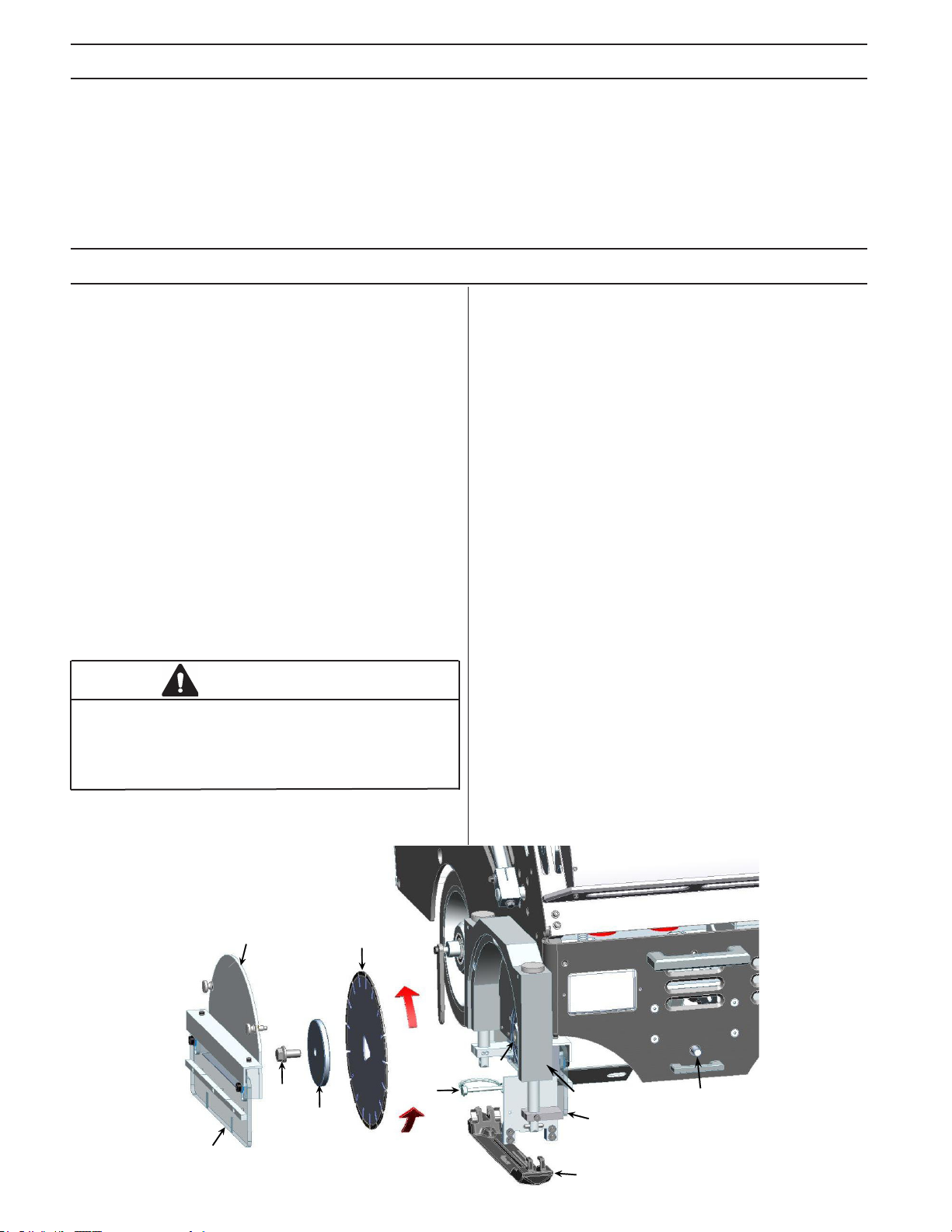
BLADE AND SKID PLATE INSTALLATION
Step 1
Turn the key switch (located on the instrument panel) to the
“ON” or “1” position. Press the blade depth rocker switch in the
instrument panel to raise the saw to its full height. Turn the key
to the “OFF” or “0” position.
Step 2
Remove the blade block cover (A) by turning the two locking
knobs counter-clockwise. Insert the blade wrench supplied
with the saw on the blade shaft bolt (B) on the end of the blade
shaft in the blade block (C). Rotate the blade shaft counterclockwise with the wrench on the blade shaft bolt (B) while
pushing in on the blade shaft locking pin (D) located on the
front of the saw frame. The locking pin will drop in the blade
shaft and prevent the shaft from rotating.
Step 3
Remove the blade shaft bolt by continuing to turn the bolt
counter-clockwise. Remove the outer arbor washer or ange
(E).
WARNING
Inspect the blade (K) for any damage. Do not use any
blade that has cracks, nicks, aws or a damaged arbor.
Make sure the blade is marked with a maximum operating speed greater than 3200 rpm.
Step 4
Match the blade tri-arbor to the blade shaft arbor (F) and install
the blade rmly against the rear ange (F). Insure the blade is
installed on the tri-arbor correctly. Match the female tri-arbor of
the outer washer or ange with the blade shaft and install the
blade shaft bolt turning clockwise while holding the locking pin
in. Be sure the outer ange is fully seated and rmly holding
the diamond blade in position.
Step 5
Install a new skid plate (G) by hooking the front on the front
blade block shaft pin. Connect the rear blade block shaft and
the rear of the skid plate by installing the locking pin (H).
Step 6
Install the blade cover by turning the two knobs and tighten until fully seated against the blade block. Lift the front and rear of
the skid plate to insure the blade slides through the skid plate
freely.
Step 7
Insure the lexan shields (I & J) move freely up and down.
When replacing a worn blade, thoroughly clean the concrete
from blade block and blade cover before installing the new
blade. Discard the old skid plate and replace it with a new skid
plate.
NOTE:
The patented skid plate is the most important part of the
Soff-Cut Ultra Early Entry system. If it is bent, twisted or
damaged, spalling and raveling of a cut may result. Store
skid plates carefully and install them properly. Install a
new skid plate with each new blade. Never re-use skid
plates.
A
K
F
B
E
H
C
D
J
I
G
6
Page 7

WHAT IS WHAT
G
H
A
B
C
V
D
U
E
F
L
I
J
K
L
O
M
N
T
S
R
P
Q
What is what?
A. Choke
B. Circuit breaker
C. Engine on/off switch
D. Emergency stop switch
E. Tachometer
F. Hour meter/Volt meter
G. Saw forward speed switch
H. Guide switch
I. Engine speed switch
J. Transmission neutral light
K. Digital display
L. Max blade depth indicator
M. Light switch
N. Handle bar height switch
O. Blade depth switch
P. Rear access panel
Q. Rear guide
R. Side light
S. Cut depth pointer
T. Blade block
U. Hood
V. Center lifting frame
W. Fuel cap
X. Fuel shut off lever
Y. Oil dipstick & ll
Z. Battery
Model number and serial
number
Y
W
X
Z
7
Page 8

OPERATING INSTRUCTIONS
Control panel
Rear guide
Blade block
Hood
To start the engine, turn the fuel valve (X) on by the carburetor
on the side of the engine. Turn the key switch (C) to the “ON”
or “1” position to activate the rocker switches. Raise the saw
by pushing the blade rocker switch (O) on the instrument panel
to the full up position. Push the saw forward speed rocker
switch (G) into neutral indicated by the red light (J) on the
instrument panel. Make sure the red emergency stop button
(D) is in the “up” position. The saw will not start unless the
emergency stop is “up”.
Close the engine choke (A) by pulling up on the knob. The
closed choke position enriches the fuel mixture for starting a
cold engine. The open choke position provides the correct fuel
mixture for operation after the engine starts and for restarting
a warm engine. Start the engine by turning the key switch (C)
to “START” or “2” position and release once the engine starts.
Slowly open the choke (A) by pushing down on the knob. Allow
the engine to warm for a few minutes.
NOTE:
The hour meter (F) runs when the key is “ON” even if the
motor is not running.
WARNING
Front guide wheel
Experience is very important when running the 2500 saw. A
skilled worker is highly recommended. Always do an inspection
of the saw before starting the engine. Check the fuel (W) and
oil level (Y) per the enclosed engine manual. SAE 10W/30 oil
and unleaded gasoline with an 87 or higher octane should be
used. The hydrostatic tansmission use Mobil DTE 26 hydraulic
oil or equivalent (20W with viscosity of 68). Observe all safety
regulations for the safe handling of fuel. Always check the
engine oil with the saw turned off, completely lowered and
the engine level! Check that all controls are in good work-
ing order. Check for loose bolts or nuts. Check for fuel or oil
leaks. Insure all guards are secure, undamaged and properly
installed.
WARNING
Do not operate saw if there is a fuel leak!
WARNING
Do not operate the saw unless all guards, safety
equipment and the engine kill switch are in place and
operational!
ASPHYXIATION HAZARD
Running an engine in a conned or badly ventilated
area can result in injury or death due to asphyxiation
or carbon monoxide poisoning.
Open the engine throttle lever to full open position for maximum engine speed by pushing the engine speed rocker switch
(I). Lower the front guide to the full down position by depressing the guide arm rocker switch (H).
Line up the saw with the cut line using the front guide wheel,
the rear guide (Q), and the triangle pointer on the back of the
blade block. Press the blade rocker switch (O) to lower the
blade in the concrete slowly to the desired depth (S) shown on
the back of of the blade block. The depth gauge lights (L) on
the instrument panel and on the right side of the saw turns off
when the blade is at full depth.
Move the saw forward by tapping the forward speed rocker
switch (G) until the desired cutting speed is reached. If the
depth gauge light turns on, slow the forward speed to insure
full cutting depth. Keep the front guide wheel on the cut line to
insure straight cuts. Make small adjustments by applying side
side pressure on the handle to keep the saw straight.
Check the air lter and clean or replace if necessary. Check
for proper specication of blade and that the skid plate oper-
ates properly. Check that the blade and skid plate are in good
condition. Make sure the work site is clean, well lit and hazard
free.
Move the saw at about half speed for the rst 100 feet to allow the blade to develop good diamond exposure or open up
and promote full blade life. Increase the forward speed of the
saw until the blade and the engine are working at maximum
efciency.
8
Page 9

cont...
Increase the forward speed if the saw is pulling left. Decrease
the forward speed if the saw is pulling right. Do not force the
saw. When approaching a wall, raise the front guide and use
the triangle guide at the back of the blade block to cut the last
few feet.
Do not hit the blade block assembly against any object.
Damage may result. Slow the forward speed by pressing the
forward speed rocker switch (G) until the saw stops. Press the
blade rocker switch (O) to raise the saw out of the cut to full
“UP” position.
DIGITAL DISPLAY (K)
The digital display in the center of the instrument panel indicates the travel speed of the saw and the total distance cut
by the saw. Push the left arrow button until the display shows
“R” on the left of the display. The unit is set to show the travel
speed of the saw in feet/minute in the US and meters/minute
outside the US. Pressing the left arrow button again changes
the display to the total distance cut by the saw. The R button
on the right resets the cut distance to zero.
The self propel function of the saw will not operate with the unit
in a raised position. Press the engine speed rocker switch (I)
to lower the engine speed. Turn the engine kill switch to the
“OFF” or “0” position. Lower the saw to the down position.
WARNING
Do not leave the saw unattended while the engine
is running! Always secure the saw from movement
while unattended.
NOTE:
Do not walk on the joints or transport equipment across
the joints until the concrete fully hardens.
Periodically, clean any excess concrete from inside the blade
block, scrapers and blade block cover. Always clean the blade
block assembly thoroughly before storing the saw.
HOUR METER/VOLT METER GAUGE (F)
The hour meter and volt meter are incorporated in the same
gauge. With the engine running, the volt meter is operating.
The gauge reads the total saw hours when the engine is not
running.
TACHOMETER GAUGE (E)
The tachometer gauge provides the engine speed in revolutions per minute (rpm).
WARNING
Before each use, carefully inspect the 2500 for any
damage to any of its parts and components. Pay
careful attention to any leakage of gasoline or oil.
Under no circumstance should the 2500 or any of
its attachments be operated if you nd damage or
are suspicious that something appears to be damaged.
9
Page 10

FUEL HANDLING
OIL HANDLING
WARNING
Taking the following precautions will lessen the risk
of injury and property damage:
- Use extreme care in handling gasoline. It is
extremely ammable and the vapors are explosive.
- Extinguish all cigarettes, cigars, pipes, and other
sources of ignition.
- Use only approved gasoline containers.
- Never remove gas cap or add fuel with the engine
running. Allow engine to cool a minimum of 3
minutes before refueling.
- Never fuel the machine indoors.
- Never store the machine or fuel container where
there is an open ame, spark, or pilot light such as
on a water heater or other appliances.
- Never ll containers inside a vehicle or on a truck
or trailer bed with a plastic liner. Always place
containers on the ground away from your vehicle
when lling.
- Remove the 2500 from the truck or trailer and
refuel it on the ground. If this is not possible, then
refuel the equipment with a portable container,
rather than from a gasoline dispenser nozzle.
- Keep the nozzle in contact with the rim of the fuel
tank or container opening at all times until fueling is
complete. Do not use a nozzle lock-open device.
- If fuel is spilled on clothing, change clothing
immediately.
- Never overll fuel tank. Always wipe off any spilled
fuel or oil. Replace fuel cap and tighten
NOTICE
Used oil is a hazardous waste product. Dispose
of used oil properly. Do not discard with household
waste. Check with your local authorities, service
center, or dealer for safe disposal/recycling facility.
ENGINE OIL
Oil Recommendation
The engine holds approximately 1.2 quart (1.1 liter) when
changing oil.
- Use a 4-stroke automotive detergent oil of API service class
SE or higher grade.
- Do not use special additives.
- Choose a viscosity according to the table below.
Please read the enclosed Honda Operator’s Manual for complete oil information.
PROPER FUEL
The Honda engine is certied to operate on automotive unleaded gasoline with a pump octane rating (M+R) of 87 or
higher. Fuel tank capacity is 1.7 gallon (6.5 liter).
Refuel in a well-ventilated area with the engine stopped.
You may use regular unleaded gasoline containing no more
than 10% ethanol (E10). Do not use gasoline containing
methanol.
Use of fuels with an ethanol content of more than 10% (E10)
may cause starting and/or performance problems. It may also
damage metal, rubber, and plastic parts of the fuel system, as
well as posing a re hazard.
Do not use fuel that is older than 30 days. Old fuel can cause
running problems as well as fuel system damage.
The engine will not operate on gasoline
marketed as E-85 (85% ethanol)
HYDROSTATIC TRANS OIL
Mobil DTE 26 hydraulic oil or equivalent (20W with viscosity
of 68)
10
Page 11

ENGINE AND TRANSMISSION MAINTENANCE
Engine Oil
Checking, Adding and Changing Oil
Check the engine oil level (A) daily with saw fully lowered and
the engine level. See the enclosed Kohler manual for more
details.
Use SAE 10W-30 viscosity detergent automotive type with API
service class SE or higher grade oil.
Note: Engine holds approximately 1.2 quart (1.1 liter) when
changing oil and oil lter.
Changing the Oil
Change oil after the rst 5 to 8 hours of use.
Thereafter every 50 hours.
C
Air lter
The air cleaner assembly (C) is a cyclone type that can be
accessed from the hood of the saw. The air cleaner element
should be replaced every 50 hours. Refer to the supplied engine manual and the “Cyclone Dual-Filter-Element Type” for
additional information.
ADDITIONAL ENGINE INFORMATION
Please see the Kohler Operator’s Manual for additional information about servicing the engine.
The manual also has specic information about specications,
tune-up parts, engine warranty, emission compliance, etc.
D
A
B
The oil drain (B) is located at the left side of the saw.
1. With the engine OFF but still warm, place a pan under the
drain and remove the brass cap.
2. Replace the brass cap on the oil drain.
3. Using a long neck funnel, ll the engine with 1.2 quarts (1.1
liters) of oil. When full, the oil level should be at the top of the
crosshatch marks on the dipstick or to the top of the of the
threads on the engine ll hole.
The engine is equipped with an oil alert system that will
stop the engine if the oil level is low.
NOTICE
Used oil is a hazardous waste product. Dispose of
used oil properly. Do not discard with household
waste. Check with your local authorities, service
center, or dealer for safe disposal/recycling facility.
E
Transmission oil
Check the transmission oil level daily. The transmission is accessible from the rear access panel of the saw. The oil reservoir (D) located on the top of the transmission has an oil level
line 1/8” (3 mm) from the bottom of the reservoir to indicate the
proper uid level when cold. Use hydraulic oil 20W with viscosity of 68 Mobil DTE 26 or equivalent.
Transmission neutral
With the saw transmission neutral light illuminated, the saw
should fully stop and not creep or move. To adjust the transmission neutral position, open the rear access panel. In the
lower right hand side, turn the transmission adjustment knob
(E) until the saw stops completely with the transmission neutral
light illuminated.
11
Page 12

OTHER MAINTENANCE
Battery
The battery is maintenance free. If the battery ever requires
charging, use only a voltage regulated taper current charger
designed specically for sealed lead acid gel cell batteries
rated at 2 amps or less (part # 505583501). A standard automotive, or any other type, battery charger not designed specically for sealed gel batteries will cause permanent damage to
the installed battery and void any warranty. Do not leave the
ignition key in the “ON” position as this will drain the battery.
There is a manual recoil start on the side of the engine that
can be used to start the engine if the battery is to low for the
elctric start to function.
WARNING
- Connecting and disconnecting a battery can cause
sparks and short circuits. Do not short battery terminals by allowing a wrench or any other object to
contact both terminals at the same time.
- A spark or ame can cause a lead acid battery to
explode.
- Before connecting a battery, remove metal
bracelets, wristwatch bands, rings, etc. Use gloves
and protective glasses or face shield when working
with a battery.
Saw controls
Inspect all controls for proper function daily. Check all the interlocks for operation especially the red emergency stop
button and engine on/off switch for proper operation.
Belts
Inspect the blade drive belt and transmission belt for cracks or
signs of wear. The belt tension is controlled by belt tensioners
and does not require adjustment. Inspect the belt tensioners
for free movement up and down. Insure the belt tensioner
bearings roll freely.
Blade shaft bearings
Lubricate the blade shaft bearings with 3 pumps of Lithium 12
based grease every 50 hours.
Cleaning
Clean the blade block of any excess concrete build up after
each use. Keep the handle bars and controls clean and dry.
Immediately clean any spilled fuel from the saw. Keep all
openings and slot on the saw clean and open so air ows free-
ly through the engine compartment to insure proper cooling.
Eye Protection Explosion Danger
Guards
Check all guards for damage and proper function daily especially the blade block. Blade block and cover should be secure
to the saw and not damaged. Lexan side covers on the blade
block should move freely up and down.
Diamond blade
Inspect diamond blades daily for damage, cracks, secure t
to the arbor, loss of segments, warping or overheating. If any
blade shows any of these problems, discard the blade and
never use.
Skid plate
Inspect the skid plate daily for damage, excessive wear in the
blade slot, burrs on the concrete surface side, twisting and free
movement up and down when installed on the blade block.
Replace the skid plate with each new diamond blade. Never
reuse the skid plates or spalling and raveling may result.
Protective Gloves
MAINTENANCE SCHEDULE
Check guarding, diamond blade, Daily
skid plate, lexan covers, controls and oil levels.
Clean blade block assembly and saw. Daily
Replace air cleaner. Every 50 hours
Replace engine oil. Every 50 hours
Grease blade shaft bearings. Every 50 hours
Check blade drive belt, the transmission Every 50 hours
drive belt and belt tensioners.
WARNING
Do not modify the saw! Use only Husqvarna Construction Products replacement parts. Use of unauthorized
parts may create a danger or damage the engine.
12
Page 13

SAWING CONTRACTION JOINTS
As concrete hydrates or cures and begins to set, it develops internal stresses which may cause random cracks. Random
cracks cast doubt on the quality and workmanship of the concrete. Contraction joints are cut in concrete to relieve these
stresses before they seek their own relief in the form of random crack. The Soff-Cut Ultra Early Entry system controls random
cracking through the early timing of a saw cut at predetermined locations to create weakened planes in the concrete that
subsequently crack at the bottom of the cut to relieve stress. Husqvarna sawed contraction joints should be a minimum of
1/8th the concrete depth and a minimum of 1” (25mm) deep. Contraction joints should be sawn as soon as the concrete will
support the weight of the saw and the operator without marking or damaging the concrete. There are many possibilities for
joint layout. Joint layout should be provided, the saw contractor should submit a detailed joint layout for approval prior to cutting. Several factors affect joint spacing including:
• Concrete thickness
• Type, amount and location of reinforcement
• Shrinkage potential of concrete-cement (type, quantity), aggregate (size, quantity, quality), water to cement ratio,
admixtures, concrete temperature
• Base friction
• Slab restraints
• Layout of foundations, racks, pits, equipment pad, trenches, etc.
• Environmental factors - temperature, wind, humidity
• Methods and quality of concrete curing.
Generally, contraction joint patterns should divide slabs into approximate square panels per the recommended spacing
shown.
RECOMMENDED CONTRACTION JOINT SPACING
Concrete thickness, in. (mm) Maximum spacing, ft. (m)
3.5 (90) 8 (2.4)
4, 4.5 (100, 114) 10 (3.0)
5, 5.5 (125, 140) 12 (3.6)
6 (150) or greater 15 (4.5)
At all intersecting cross cuts, install Husqvarna joint protectors at each joint to prevent joint damage. Install an additional joint
protector where the right wheel will cross the joint to prevent concrete damage.
13
Page 14

MAXIMIZING THE SOFF-CUT SYSTEM
“ The timing of concrete operations - especially nishing and jointing - is critical”, states a quote from the foreword of
the American Concrete Institute (ACI) 302.1 R-96. It goes on to say that “Failure to address this issue can contribute to undesirable characteristics in the wearing surface as cracking...” (It mentions other problems).
The patented Soff-Cut Ultra Early Entry system has revolutionized the method used to control random cracking. While Soff-
Cut is being specied more today than ever, sometimes the ultra early-entry spec is not always followed on the job site. In
order for the Soff-Cut system and an experienced Husqvarna contractor to do a satisfactory job, four components must exist
to meet the “specication”:
1. A Soff-Cut Ultra Early Entry dry up-cut saw
2. A Husqvarna Excel Series dry-cutting diamond blade
3. A Husqvarna anti-ravel skid plate installed with every new diamond blade
4. An operator skilled in using the Soff-Cut Ultra Early Entry cutting system.
Without this, joints can not be cut clearly enough to control random cracking before it starts, which is what the building owner
is paying for.
The ACI Spec 302.1R-96 says it best:
“Early-entry dry-cut saws use diamond-impregnated blades and a skid plate that helps prevent spalling. Timely changing of skid plates is necessary to effectively control spalling. It is best to change skid plates in accordance with manufacturer’s
recommendations...The goal of saw-cutting is to create a weakened plane as soon as the joint can be cut...The timing of the
early-entry process allows joints to be in place prior to development of signicant tensile stress in the concrete...”
The Portland Cement Association (PCA) engineering bulletin, Concrete Floors on the ground, also states:
“Proper jointing can eliminate unsightly random cracks. Aspects of joining that lead to a good job are choosing the
correct type of joint for each location, establishing a good joint pattern and layout, and installing the joint at the correct time...
Timing of joint sawing is critical...Lightweight, high-speed, early-cut saws have been developed to permit the joint sawing
very soon after oor nishing, sometimes within 0 to 2 hours...if the cut is sawn within a few hours after the nal nishing,
random cracking can be controlled...”
Husqvarna has the only Ultra Early Entry dry-cutting system (Soff-Cut) which controls random cracking through the early tim-
ing of the cut. With the patented Soff-Cut method, control joints are usually cut within 0 to 2 hours after the nishing process.
Joint cutting should begin as soon as the concrete will support the weight of the saw and the operator at each joint location
and before nal set. If the joints are not being cut within this time frame then the Soff-Cut Ultra Early Entry method is not being followed and building owners are not getting what they are paying for or the nished product that they expect.
We hope this information is benecial to building owners, general contractors, concrete nishers, saw operators and the
entire industry. For additional information, contact Husqvarna Construction Products at (951) 272-2330 or (800) 776-3328, or
see our website www.husqvarnacp.com.
14
Page 15

TROUBLESHOOTING
SAW IS SPALLING AND RAVELLING CUT
- Check to see if the diamond blade is worn out, glazed,
warped or damaged.
ENGINE WILL NOT START
- Check that the red emergency stop button is pulled up.
- Insure skid plate moves freely up and down the entire shaft
length without contacting the diamond blade.
- Check skid plate for excessive wear or gap around the
diamond blade.
- Check skid plate for tension or loose mounts. Skid plates are
preset at the factory.
- Check bottom of skid plate for metal burrs or irregularities.
- Insure skid plate is not twisted or bent.
- Check lexan covers for free movement up and down.
- Insure there is spring down pressure at each end of the skid
plate.
- Do not twist or move the saw sideways while cutting.
- Check that the engine is running properly and at full throttle.
- Check belt and belt idler for proper tension.
- Insure the diamond blade is properly mounted and secured
with clean anges.
- Insure that the diamond blade is the correct specication for
your area.
- Insure the slab is in clean with no debris that could raise the
skid plate or saw while cutting.
- Use Husqvarna joint protectors at all cut intersections.
- Clean excess concrete debris from the blade block assembly.
- Check that the scrapers in the blade block are not bent or
binding.
- Insure that the blade block shafts are not bent or damaged.
- Check that the front diverter in the blade block is not bent and
the diverter legs are not contacting the concrete.
ENGINE RUNS ROUGH, BACK FIRES OR CAN NOT
REACH FULL SPEED
- Check if there is fuel in the tank and it is the correct fuel.
Make sure there is no water in the fuel.
- Check that the spark plug wires are connected to the spark
plugs.
- Engine is ooded. Adjust the choke per the engine owner’s
manual.
- Check that the air lter is not dirty or plugged.
- Check the choke is in the “on” position for cold starts. Adjust
the choke per the engine owner’s manual.
- Check that the blade shaft rotates freely and no concrete has
built up in the blade block.
- Check that the fuel valve is turned the “ON” position.
- Oil level is too low. Engine is equipped with an oil alert
system that will not let the engine start unless the engine oil
level is within the correct range.
SAW PULLS TO ONE SIDE WHILE SAWING
- Check front and rear guide is properly aligned with the center
of the diamond blade.
- Check to see if diamond blade is worn out, glazed, warped or
damaged.
- Do not twist or move the saw sideways while cutting. Make
gradual changes in pressure on the handlebar to control the
saw in the cut.
- Insure that all wheels rolls freely and smoothly.
- Do not force the saw. Allow the diamond blade to cut at its
own rate of speed.
- Check the skid plate for damage or burrs.
- Insure both driver tubes are contacting the rear wheels,
driver tubes are clean and rear wheels are not damaged.
- Check if there is fuel in the tank and it is the correct fuel.
Make sure there is no water in the fuel.
- Check that the spark plugs are clean and properly gapped.
- Check that choke is in the “off” position after engine is warm.
- Check that air lter is not dirty or plugged.
- Check that the throttle lever is properly set.
- Check for correct oil level. Engine oil alert system may func
tion intermittently if oil level is not within the correct range.
15
Page 16

TECHNICAL SPECIFICATIONS
Engine
Model Honda GX 390
Engine oil volume,
quarts/liters
Gasoline tank
volume, gal/liters
Type cooled, 4-cycle, single slant cylinder,
Air fi lter Cyclonic type
Oil system Oil alert with auto shut down sensor
Muffl er Silent type 100 dbA, exhaust defl ector,
Emissions Complies with EPA Phase 2 and CARB
Cooling Air cooled
Cylinder Aluminum with cast iron liner
Controls Engine mounted manual fuel shut off
Weight and Dimensions
Weight – dry, lbs/kg 336/152
Weight with gasoline and oil full, lbs/kg 348/158
Length (handle folded in), inch/mm 50/1270
Width, inch/mm 23/584
Height, inch/mm 38/965
Blade
Material cut Green concrete only
Blade type 10.0” (254 mm) or 9.0” (229 mm) dry cut
1.2/1.1
1.7/6.5
overhead valves, gasoline engine
spark arrestor
Tier II USA regulations
lever Instrument panel mounted manual
choke, electric switch operated throttle,
keyed on/off switch.
with tri-arbor
Blade rotation Counter clockwise, upcutting
Blade shaft speed,
rpm
Cutting depth 1 to 1 1/2 inch (25 to 38 mm) depending
Cutting distance
from wall, inch/mm
Average cutting rate - Estimate only. Speed will vary with job
conditions and concrete mixes.
Soft aggregates, ft/min / m/min 20/6.1
Medium aggregates, ft/min / m/min 14/4.3
Hard aggregates, ft/min / m/min 8/2.4
Blades are available in 10.0 inch (254 mm) and 9.0 inch (229 mm)
diameters and in 0.100 inch (2.5 mm), 0.250 inch (6.4 mm), 0.380
inch (9.7 mm), and 0.500 inch (12.7 mm) widths.
Noise emissions (see note 1)
Sound power level, measured dB(A) 109
Sound power level, guaranteed dB(A) 110
Sound levels (see note 2)
Sound pressure level at the operators ear, dB(A) 91
Vibration levels, ahv (see note 3)
Handle right, m/s
Handle left, m/s
Note 1: Noise emissions in the environment measured as sound
power (L
Note 2: Noise pressure level according to EN 13862. Reported
data for noise pressure level has a typical statistical dispersion
(standard deviation) of 1.0 dB(A).
Note 3: Vibration level according to EN 13862. Reported data for
vibration level has a typical statistical dispersion (standard deviation) of 1 m/s
) in conformity with EC directive 2000/14/EC.
WA
2
.
3200
on amount of blade wear
3 1/2 / 89
2
2
3,4
3,6
TECHNICAL DATA
CALIFORNIA AIR RESOURCES BOARD (CARB): This machine is considered a preempt Off-Road Application as relating to CARB standards. Under construction equipment, and in particular, as a Saws : concrete, masonry, cutoff, with engine power less than 19KW (25hp),
CARB standards do not apply to this machine.
For more information see the website http://www.arb.ca.gov/msprog/offroad/preempt.htm
EC DECLARATION OF CONFORMITY
Husqvarna AB, SE-433 81 Göteborg, Sweden, tel: +46-31-949000, declares under sole responsibility that the Husqvarna Soff-Cut 2500
dating from 2010 serial numbers and onwards (the year is clearly stated on the rating plate, followed by the serial number), complies with
the requirements of the COUNCILíS DIRECTIVE:
• of May 17, 2006 ”relating to machinery” 2006/42/EC
• of December 15, 2004 ”relating to electromagnetic compatibility” 2004/108/EC.
• of May 8, 2000 ”relating to the noise emissions in the environment” 2000/14/EC.
The following standards have been applied: EN ISO 12100:2003, EN 55014-1:2006, EN 55014-2/A1:2001, EN 61000-3-2:2006, EN 610003-3/A1/A2:2005, EN 13862/A1:2009.
Huskvarna December 29, 2009
Henric Andersson
Vice President, Head of Power Cutters and Construction Equipment
(Authorized representative for Husqvarna AB and responsible for technical documentation.)
Page 17

WARRANTY
HUSQVARNA EQUIPMENT WARRANTY
New 2500 sold by Husqvarna Construction Products are warranted to be free from manufacturing defects in normal service for a period of six (6) months for labor and up to one (1) year on parts from date of purchase by the
original consumer purchaser or date of introduction into rental company eet.
Our obligation under this warranty is expressly limited to the replacement or repair at Husqvarna Construction Products, or at a service facility designated by us, of such part or parts if inspection shall disclose it to have been defective.
This warranty does not apply to defects caused by damage, unreasonable use, faulty repairs made by others (or
defects caused by failure to provide reasonable maintenance, while in the possession of the consumer). Further, the
warranty is void if the product, or any of its components, are altered or modied by the consumer purchaser, or if the
product is used in an inappropriate manner not recommended by the manufacturer.
The use of any other blade except Husqvarna Construction Products blades and skid plates will void the warranty
and could cause internal damage to the motor.
In no event shall Husqvarna Construction Products be liable for any indirect, incidental or consequential damages
from the sale or use of the product. This disclaimer applies both during and after the term of this warranty.
This warranty gives you specic legal rights and other possible rights, which may vary from state to state. Some
states do not allow the exclusion or limitation of incidental or consequential damages so the above limitation or
exclusion may not apply to you. Some states do not allow limitations on how long an implied warranty lasts so the
above limitation may not apply to you.
WARRANTY ON ENGINE
Husqvarna Construction Products does not perform warranty repairs or reimburse for warranty repairs on engines.
Engine warranties are provided by the engine manufacturer.
To obtain warranty repair: Take your engine along with your proof of purchase to any general purpose dealer or distributor nearest you.
If you are unable to obtain warranty service or are dissatised with the warranty service you received, contact the
owner of the dealership involved. Normally, this should resolve your problem. For further assistance, call our parts
and service department at 1-800-776-3328 or 1-951-272-2330.
WARRANTY ON REPLACEMENT PARTS
There is a three (3) months warranty from date of purchase on all replacement parts.
COPYRIGHT 2009 HUSQVARNA CONSTRUCTION PRODUCTS
Covered by one or more of the following U.S. Patents
4769201, 4889675, 4928662, 4938201, 5056499, 5086750, 5184597, 5303688, 5305729, 5373834, 5441033,
5505189, 5507273, 5570677, 5575271, 5579754, 5582899, 5603310, 5660161, 5664553, 5666939, 5689072,
58030371, 6892719, 6990972, 7073495, 7163010, 7258115.
Other U.S. and foreign patents pending.
17
Page 18

´®z+UOe¶5y¨
´®z+UOe¶5y¨
www.husqvarnacp.com
Original instructions
1153476-95
2014-09-24
 Loading...