

Page 1
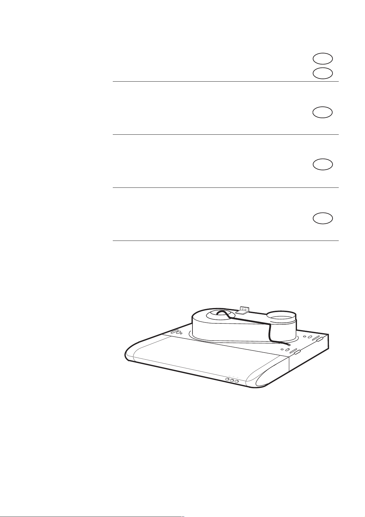
Bruksanvisning
S
N
Brugsanvisning
Käyttöohjeet
User manual
=
FLÄKT • KJØKKENVENTILATOR
DK
F
UK
• LIESITUULETIN • EMHÆTTE • COOKER HOOD
==
821 27 45-04
QC 520, QC 620, QC 720
Page 2
SERVICE
Fläkten är tillverkad i moduler, vilket underlättar vid service.
S
Ventilatoren er bygget opp av moduler slik at det kun er nødvendig å bytte små detaljer ved
N
eventuelt behov for service.
Emhætten er fremstillet i moduler, så de enkelte dele kan udskiftes ved hætter evt. service.
DK
Liesituuletin on moduulirakenteinen siten, että huollon yhteydessä pitää vaihtaa vain pieniä osia.
FI
Built in modules so that only small parts need replacing at service.
UK
Fläkten kan förses med ett TVÄTTBART högeffektivt kolfilter.
S
Ventilatoren kan utstyres med et meget effektivt, VASKBART kullfilter.
N
Emhætten kan monteres med VASKBART højeffektivt kulfilter.
DK
Liesituulettimessa voidaan käyttää PESTÄVÄÄ korkeatehoista hiilisuodatinta.
FI
A highly-effective, WASHABLE carbon filter can be fitted to the hood.
UK
Ytbehandlingen har skett med lösningsmedelsfri pulverlackering.
S
Ventilatoren er overflatebehandlet med pulverlakk uten løsningsmidler.
N
Lakeringen er foretaget med pulverlak som er fri for opløsningsmiddel.
DK
Pintakäsitelty liuotinvapaalla jauhemaalilla (polttomaalaus).
FI
The hood has been finished with a non-solvent paint.
UK
75 W 11 W
Fläkten har lågenergilysrör på 11 W. Detta motsvarar en normal glödlampa på 75 W.
S
Ventilatoren har lavenergi lysrør på 11 W. Lysmessig tilsvarer dette en vanlig glødelampe på 75 W.
N
Emhætten har lavenergilysstofrør på 11 W. Dette svarer til en alm. glødetrådspære på 75 W.
DK
Liesituulettimessa on 11 W energiansäästölamppu, joka vastaa 75 W normaalia hehkulamppua.
FI
The hood's 11 W low-energy fluorescent strip light provides the same light as an ordinary 75 W
UK
bulb.
Fabriken källsorterar: Plåt, wellpapp, trä, papper och cellplast.
S
Fabrikken kildesorterer sitt avfall. Stål, tre, papir, papp og plast.
N
Fabrikken sorterer affald: Metal, pap, træ, papir og plast.
DK
Tehdas kierrättää: Pellit, pakkausmateriaalin, puun, paperin ja muovin.
FI
Metal, cardboard, wood, paper and cellular plastic are sorted for recycling at the factory.
UK
2
Page 3

S
=fååÉÜ™ääëÑ∏êíЙЕвебåÖ
Säkerhetsinformation ...................................................................4
Beskrivning av köksfläkten .........................................................5
Så här använder du din fläkt .....................................................6
Skötsel och rengöring...................................................................6
Om fläkten inte fungerar ............................................................8
Tekniska data ................................................................................. 8
Installation .......................................................................................9
N
=fååÜçäÇëÑçêíÉÖåÉäëÉ
Sikkerhetsforskrifter................................................................... 11
Beskrivelse av ventilatoren....................................................... 12
Bruk av ventilatoren .................................................................. 13
Vedlikehold og Rengjøring......................................................... 13
Dersom ventilatoren ikke fungerer........................................ 15
Tekniske data .............................................................................. 15
Installasjon.................................................................................... 16
DK
=fåÇÜçäÇëÑçêíÉÖåÉäëÉ
Sikkerhedsinformation............................................................... 18
Beskrivelse af emhætten .......................................................... 19
Sådan benyttes emhætten ....................................................... 20
Vedligeholdelse og rengøring ................................................... 20
Hvis emhætten ikke fungerer.................................................. 22
Tekniske data .............................................................................. 23
Installation .................................................................................... 24
FI
=páë®ääóëäìÉííÉäç
Turvallisuustietoa ........................................................................ 26
Liesituulettimen kuvaus ............................................................ 27
Liesituulettimen käyttö.............................................................. 28
Hoito ja puhdistus...................................................................... 28
Jos liesituuletin ei toimi ............................................................. 30
Tekniset tiedot ............................................................................. 30
Asennus......................................................................................... 31
UK
=`çåíÉåíë
Safety instructions ...................................................................... 33
Description of the cooker hood .............................................. 34
Using the cooker hood .............................................................. 35
Maintenance and cleaning ...................................................... 35
If the hood does not function.................................................. 37
Technical data ............................................................................. 37
Installation .................................................................................... 38
3
Page 4

=p~ÑÉíó=áåëíêìÅíáçåë
The cooker hood may only be used in a private household and for normal cooking purposes. It fulfils international
safety regulations and standards of quality. All precautionary measures however cannot fully eliminate all the acci-
dent risks.
Therefore you should read through instructions, advises and safety instructions carefully before you install and
start using the cooker hood. Pay special attention to sentences with a warning triangle to avoid damages to person
or property . Save the instruction boook for future reference if the cooker hood is sold or left to another person.
Use of cooker hood
• Never leave any deep-frying, melting fat,
paraffin or any other inflammable unattended on
the hob. If event of fire: Immediately switch off
the cooker hood and the cooker.
the fire. Never use water.
• Never do any flambé cooking underneath the
cooker hood. It can cause a fire. Remember that
overheated fat may spontaneously ignite. Never
leave the fraying pan unattended.
• It is essential that the grease filter is regularly
cleaned to avoid fat to drip on to the hot zone
and cause fire. Read also the part “Maintenance
and Cleaning” in the instruction book.
Note!
Cover
Disposal
• Prevent accidents when disposing your cooker
hood. Disconnect the power plug from the wall
socket and cut the power cord at the hood inlet.
Contact your local authority for information on
where to dispose the cooker hood.
Guide to use the Instructions
Installation and service
• Any electrical installation of the cooker hood
must be carried out by a qualified ele ctrician and
the hood itself must be installed by someone
with experience. Installation made by an
unqualified person can lead to loss of function
of the cooker hood and possible damage to
person and/or property.
• The cooker hood must be at least 40 cm above
electric burners or electric range, or at least 65
cm above gas burners or gas range.
• Ensure that the power cord does not get
squeezed at the installation.
• The cooker hood is only currentless when the
plug or the fuse is disconnected.
• Laws and regulations which apply to the way
exhaust air should be removed must be
observed. For example, the exhaust air may not
be taken into flues that are used for the removal
of fumes from consumables, which are fed with
types of energy other than electrical energy,
such as oil-fired boilers or wood-burning stoves.
The following symbols will be found in the text to
guide you throughout the Instructions:
Safety instructions
Environmental information
33
Page 5
aЙлЕкбéíáçå=çÑ=íÜÉ=ÅççâÉê=ÜççÇ
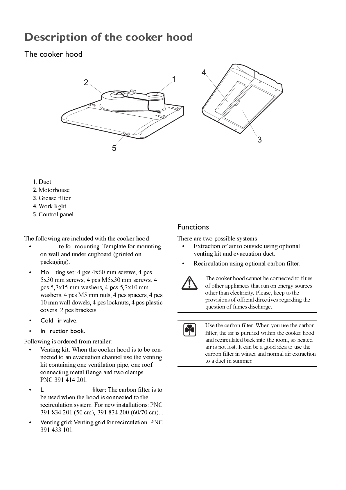
The cooker hood
1
1.
Duct
2.
Motorhouse
3.
Grease filter
4.
Work light
5.
Control panel
2
5
4
3
Accessories
The following are included with the cooker hood:
•
Template for mounting:
on wall and under cupboard (printed on
packaging).
•
Mounting set:
5x30 mm screws, 4 pcs M5x30 mm screws, 4
pcs 5,3x15 mm washers, 4 pcs 5,3x10 mm
washers, 4 pcs M5 mm nuts, 4 pcs spacers, 4 pcs
10 mm wall dowels, 4 pcs locknuts, 4 pcs plastic
covers, 2 pcs brackets.
• Cold air valve.
•
Instruction book.
Following is ordered from retailer:
• Venting kit: When the cooker hood is to be con-
nected to an evacuation channel use the venting
kit containing one ventilation pipe, one roof
connecting metal flange and two clamps.
PNC 391 414 201.
•
LONG LIFE carbon filter:
be used when the hood is connected to the
recirculation system. For new installations: PNC
391 834 201 (50 cm), 391 834 200 (60/70 cm). .
4 pcs 4x60 mm screws, 4 pcs
Template for mounting
The carbon filter is to
Functions
There are two possible systems:
• Extraction of air to outside using optional
venting kit and evacuation duct.
• Recirculation using optional carbon filter.
The cooker hood cannot be connected to flues
of other appliances that run on energy sources
oth er th an el ectri ci ty. Plea se , ke ep to th e
provisions of official directives regarding the
question of fumes discharge.
Use the ca rbon filte r. When you u se th e carbo n
filter, the air is purified within the cooker hood
and recirculated back into the room, so heated
air is not lost. It can be a good idea to use the
carbon filter in winter and normal air extraction
to a duct in summer.
•
34
Venting grid:
391 433 101.
Venting grid for recirculation. PNC
Page 6
rëáåÖ=íÜÉ=ÅççâÉê=ÜççÇ
Correct ventilation
If the cooker hood should be working correctly there
must be an underpressure in the kitchen. It is important
to keep the kitchen windows closed and have a win-
dow in an adjacent room open.
Important to know
Great care must be taken if the hood is used at the
same time as a burner or fireplace (e.g. gas, diesel, c oal
or wood heaters, water heaters, etc.), as the hood will
expel air which is required by these other appliances.
Atten d to it by ope n i n g a w i n do w. No t appli c a ble for
cooker hoods used in recirculation mode.
Do not operate the fan at a higher speed th an
necessary. The low speeds are adequate for
ordinary requirements while cooking. The high
speeds should be used only if food has burnt
while cooking, or for other strong fumes.
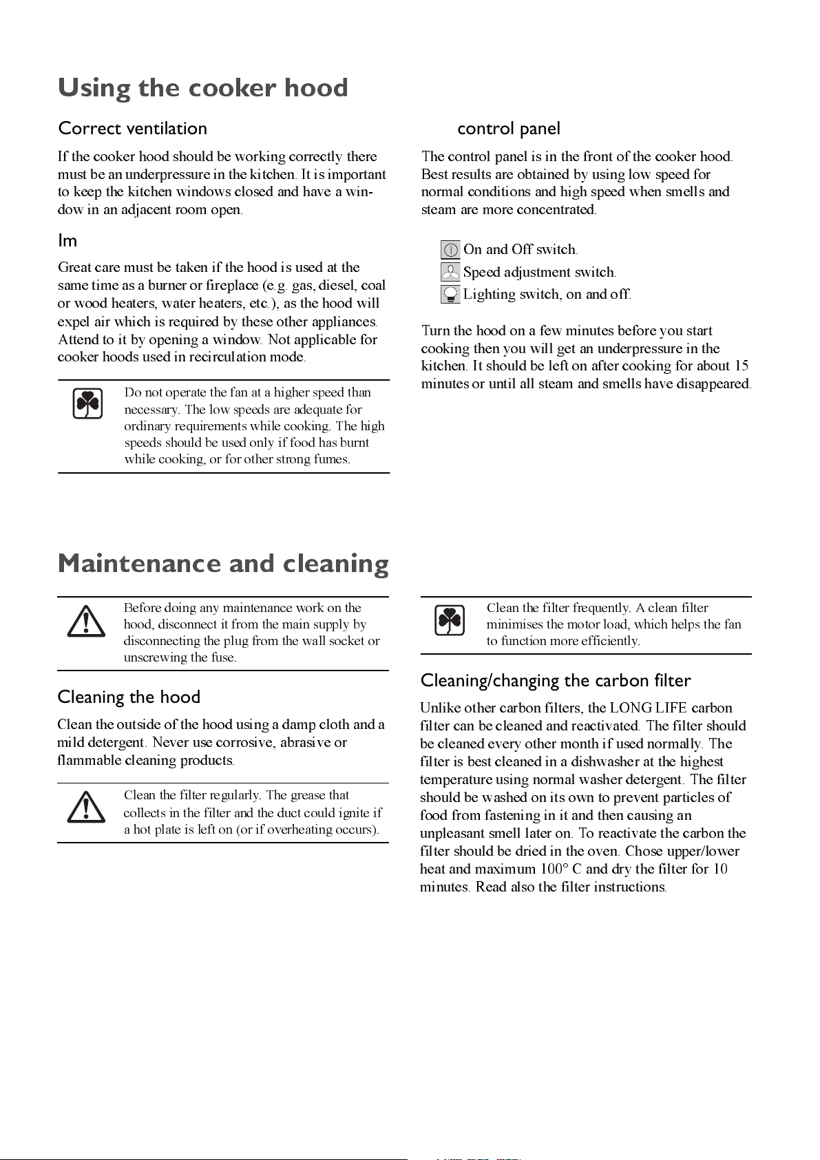
The control panel
The control panel is in the front of the cooker hood.
Best results are obtained by using low speed for
normal conditions and high speed when smells and
steam are more concentrated.
On and Off switch.
Speed adjustment switch.
Lighting switch, on and off.
Turn the hood on a few minutes before you start
cooking then you will get an underpressure in the
kitchen. It should be left on after cooking for about 15
minutes or until all steam and smells have disappeared.
j~áåíÉå~åÅÉ=~åÇ=ÅäÉ~åáåÖ
Before doing any maintenance work on the
hood, disconnect it from the main supply by
disconnecting the plug from the wall socket or
unscrewing the fuse.
Cleaning the hood
Clean the outside of the hood using a damp cloth and a
mild detergent. Never use corrosive, abrasive or
flammable cleaning products.
Clean th e filte r regu l arly . The g rea se th a t
collects in the filter and the duct could ignite if
a hot plate is left on (or if overheating occurs).
Clean the filter frequently. A clean filter
min i m i ses the mo to r lo ad , w h ic h hel ps th e fan
to function more efficiently.
Cleaning/changing the carbon filter
Unlike other carbon filters, the LONG LIFE carbon
filter can be cleaned and reactivated. The filter should
be cleaned every other month if used normally. The
filter is best cleaned in a dishwasher at the highest
temperature using normal washer detergent. The filter
should be washed on its own to prevent particles of
food from fastening in it and then causing an
unpleasant smell later on. To reactivate the carbon the
filter should be dried in the oven. Chose upper/lower
heat and maximum 100° C and dry the filter for 10
minutes. Read also the filter instructions.
35
Page 7
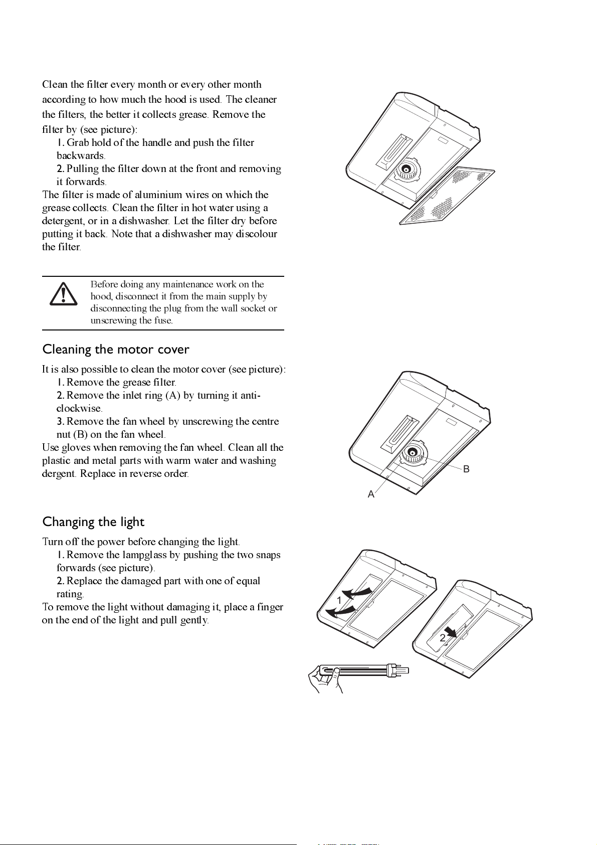
Cleaning the grease filters
Clean the filter every month or every other month
according to how much the hood is used. The cleaner
the filters, the better it collects grease. Remove the
filter by (see picture):
1.
Grab hold of the handle and push the filter
backwards.
2.
Pulling the filter down at the front and removing
it forwards.
The filter is made of aluminium wires on which the
grease collects. Clean the filter in hot water using a
detergent, or in a dishwasher. Let the filter dry before
putting it back. Note that a dishwasher may discolour
the filter.
Before doing any maintenance work on the
hood, disconnect it from the main supply by
disconnecting the plug from the wall socket or
unscrewing the fuse.
Cleaning the motor cover
It is also possible to clean the motor cover (see picture):
1.
Remove the grease filter.
2.
Rem o v e the in l e t ri ng (A ) by turnin g it an ti-
clockwise.
3.
Remove the fan wheel by unscrewing the centre
nut (B) on the fan wheel.
Use gloves when removing the fan wheel. Clean all the
plastic and metal parts with warm water and washing
dergent. Replace in reverse order.
Changing the light
Turn off the power before changing the light.
1.
Remove the lampglass by pushing the two snaps
forwards (see picture).
2.
Replace the damaged part with one of equal
rating.
To remove the light without damaging it, place a finger
on the end of the light and pull gently.
B
A
1
2
36
Page 8
fÑ=íÜÉ=ÅççâÉê=ÜççÇ=ÇçÉë=åçí=ÑìåÅíáçå
Before calling for service
Check the plug is correctly connected to the wall
socket. Check the fuse. Do not attempt any repairs
yourself that are likely to lead to further damage. If the
problem remains, contact your dealer or an approved
service company. Remember to save your purchase
receipt and warranty card (only used in some coun-
tries).
Service and spare parts
Your dealer or service company will supply you with
service and spare parts. Be sure you have the product
number and model name at hand when ordering serv-
ice or parts.
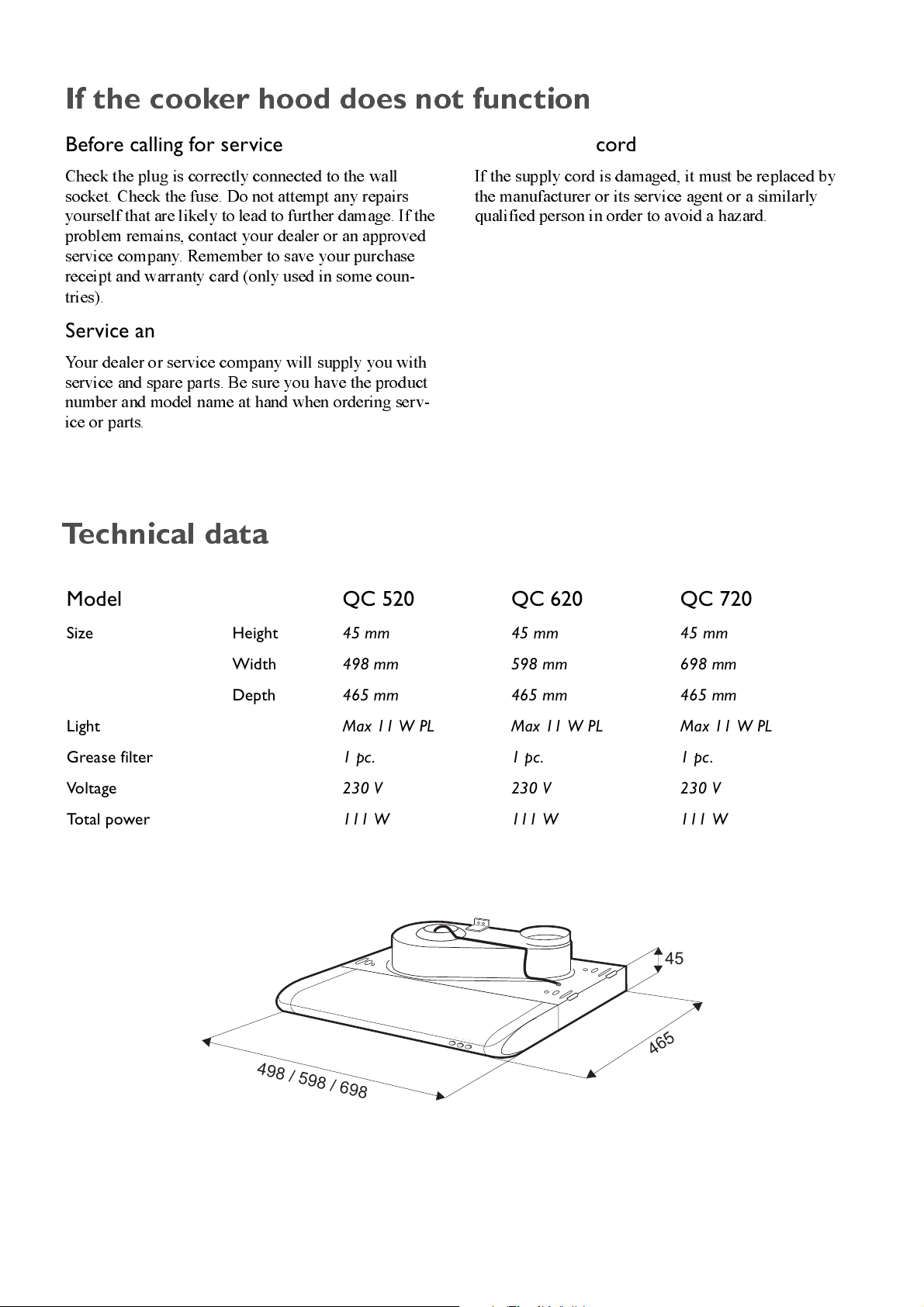
qÉÅÜåáÅ~ä=Ç~í~
Changing the cord
If the supply cord is damaged, it must be replaced by
the manufacturer or its service agent or a similarly
qualified person in order to avoid a hazard.
Model QC 520 QC 620 QC 720
Size Height 45 mm 45 mm 45 mm
Width 498 mm 598 mm 698 mm
Depth 465 mm 465 mm 465 mm
Light Max 11 W PL Max 11 W PL Max 11 W PL
Grease filter 1 pc. 1 pc. 1 pc .
Vol ta ge 230 V 230 V 230 V
To t a l p o w e r 111 W 111 W 111 W
45
465
498 / 598 / 698
37
Page 9
fåëí~ää~íáçå
Unpacking
Check that the cooker hood is not damaged.
Transportation damages should immediately be
reported to the transport company. Damages, faults
and eventually missing parts should immediately be
reported to the retailer. Dispose carefully of the
packaging material so that it is out of the way of small
children. Remove the transport supports
(see “Mounting of cooker hood on wall”).
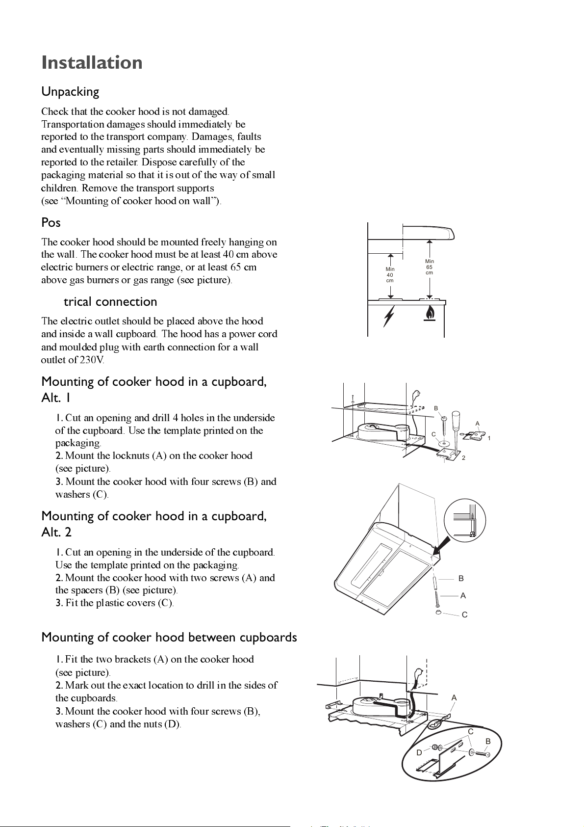
Position
The cooker hood should be mounted freely hanging on
the wall. The cooker hood must be at least 40 cm above
electric burners or electric range, or at least 65 cm
above gas burners or gas range (see picture).
Electrical connection
The electric outlet should be placed above the hood
and inside a wall cupboard. The hood has a power cord
and moulded plug with earth connection for a wall
outlet of 230V.
Min
cm
Min
65
40
cm
Mounting of cooker hood in a cupboard,
Alt. 1
1.
Cut an opening and drill 4 holes in the underside
of the cupboard. Use the template printed on the
packaging.
2.
Mount the locknuts (A) on the cooker hood
(see picture).
3.
Mount the cooker hood with four screws (B) and
washers (C).
Mounting of cooker hood in a cupboard,
Alt. 2
1.
Cut an opening in the underside of the cupboard.
Use the template printed on the packaging.
2.
Mount the cooker hood with two screws (A) and
the spacers (B) (see picture).
3.
Fit the plastic covers (C).
Mounting of cooker hood between cupboards
1.
Fit the two brackets (A) on the cooker hood
(see picture).
2.
Mark out the exact location to drill in the sides of
the cupboards.
3.
Mount the cooker hood with four screws (B),
washers (C) and the nuts (D).
B
A
C
A
D
1
2
B
A
C
C
B
38
Page 10
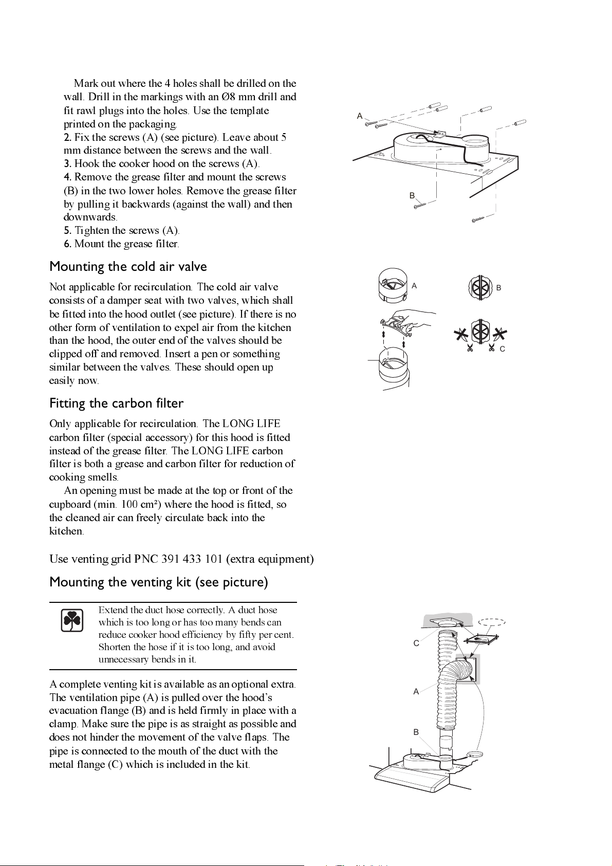
Mounting of cooker hood on wall
1.
Mark out where the 4 holes shall be drilled on the
wall. Drill in the markings with an Ø8 mm drill and
fit rawl plugs into the holes. Use the template
printed on the packaging.
2.
Fix the screw s (A) (se e pictu re ). Leave abo u t 5
mm distance between the screws and the wall.
3.
Hook the cooker hood on the screws (A).
4.
Remove the grease filter and mount the screws
(B) in the two lower holes. Remove the grease filter
by pulling it backwards (against the wall) and then
downwards.
5.
Tigh te n the sc re ws (A).
6.
Mount the grease filter.
Mounting the cold air valve
Not applicable for recirculation. The cold air valve
consists of a damper seat with two valves, which shall
be fitted into the hood outlet (see picture). If the re is no
other form of ventilation to expel air from the kitchen
than the hood, the outer end of the valves should be
clipped off and removed. Insert a pen or something
similar between the valves. These should open up
easily now.
A
B
A
B
C
Fitting the carbon filter
Only applicable for recirculation. The LONG LIFE
carbon filter (special accessory) for this hood is fitted
instead of the grease filter. The LONG LIFE carbon
filter is both a grease and carbon filter for reduction of
cooking smells.
An ope n i n g must be m ad e at the top or fron t of the
cupboard (min. 100 cm²) where the hood is fitted, so
the cleaned air can freely circulate back into the
kitchen.
Use venting grid PNC 391 433 101 (extra equipment)
Mounting the venting kit (see picture)
Extend the duct hose correctly. A duct hose
which is too long or has too many bends can
reduce cooker hood efficiency by fifty per cent.
Shorten the hose if it is too long, and avoid
unnecessary bends in it.
A complete venting kit is available as an optional extra.
The ventilation pipe (A) is pulled over the hood’s
evacuation flange (B) and is held firmly in place with a
clamp. Make sure the pipe is as straight as possible and
does not hinder the movement of the valve flaps. The
pipe is connected to the mouth of the duct with the
metal flange (C) which is included in the kit.
C
A
B
39
Page 11
S
Husqvarna Hushållsprodukter
email: info.domestic@husqvarna.se (www.husqvarna.se)
N
Husqvarna Hvitevarer
email: husqvarna@ehn.no
FI
Oy Electrolux Kotitalouskoneet Ab-Husqvarna
email: carelux.fsh@notes.electrolux.fi
DK
Husqvarna Husholdningsapparater A/S
email: ordrekontor.dkm@notes.electrolux.dk
©ABS-PCH 2002-03-08
 Loading...