


Operator's nual
anual e Operario
M24-54T
Gasoline containing up to 10% ethanol (El0) is acceptable for use inthis machine. The use of any gasoline
exceeding 10% ethanol (El0) will void the product warranty.
Esta m_quina puede utilizar gasolina con un contenido de hasta el 10% de etanol (El0). El uso de una
gasolina que supere el 10% de etanol (El0) anular_ la garantia del producto, the product warranty.
Please read the operator's manual carefully and make sure you understand the instructions before using the
machine.
Por favor lea cuidadosamente y comprenda estas intrucciones antes de usar esta maquina.
583 87 96-49 Original Instructions in English, all others are translations.
English/Spanish
Safe Operation Practices for Ride=On Mowers
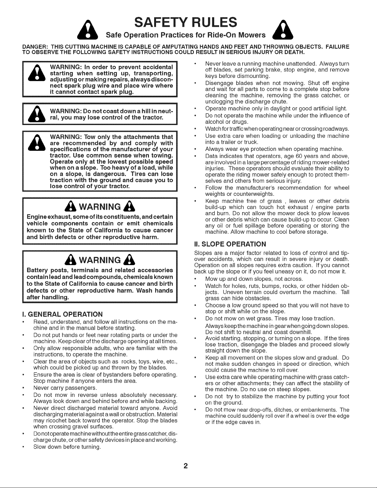
DANGER: THiS CUTTING MACHINE IS CAPABLE OF AMPUTATING HANDS AND FEET AND THROWING OBJECTS. FAILURE
TO OBSERVE THE FOLLOWING SAFETY iNSTRUCTiONS COULD RESULT IN SERIOUS iNJURY OR DEATH.
SAFETY RULES
WARNING: in order to prevent accidental
&
starting when setting up, transporting,
adjusting or making repairs, always discon=
nect spark plug wire and place wire where
it cannot contact spark plug.
WARNING: Tow only the attachments that
&
are recommended by and comply with
specifications of the manufacturer of your
tractor. Use common sense when towing.
Operate only at the lowest possible speed
when on a slope. Too heavy of a load, while
on a slope, is dangerous. Tires can lose
traction with the ground and cause you to
lose control of your tractor.
WARNING
Engine exhaust, some of its constituents, and certain
vehicle components contain or emit chemicals
known to the State of California to cause cancer
and birth defects or other reproductive harm.
WARNING
Battery posts, terminals and related accessories
contain lead and lead compounds, chemicals known
to the State of California to cause cancer and birth
defects or other reproductive harm. Wash hands
after handling.
I. GENERAL OPERATION
• Read, understand, and follow all instructions on the ma-
chine and in the manual before starting.
• Do not put hands or feet near rotating parts or under the
machine. Keep clear of the discharge opening at all times.
• Only allow responsible adults, who are familiar with the
instructions, to operate the machine.
• Clear the area of objects such as rocks, toys, wire, etc.,
which could be picked up and thrown by the blades.
• Ensure the area is clear of bystanders before operating.
Stop machine if anyone enters the area.
• Never carry passengers.
• Do not mow in reverse unless absolutely necessary.
Always look down and behind before and while backing.
• Never direct discharged material toward anyone. Avoid
discharging material against a wall or obstruction. Material
may ricochet back toward the operator. Stop the blades
when crossing gravel surfaces.
• Do not operate machinewithout the entire grass catcher, dis-
charge chute, or other safety devices in place and working.
• Slow down before turning.
• Never leave a running machine unattended. Always turn
off blades, set parking brake, stop engine, and remove
keys before dismounting.
• Disengage blades when not mowing. Shut off engine
and wait for all parts to come to a complete stop before
cleaning the machine, removing the grass catcher, or
unclogging the discharge chute.
• Operate machine only in daylight or good artificial light.
• Do not operate the machine while under the influence of
alcohol or drugs.
• Watch for traffic when operating near or crossing roadways.
• Use extra care when loading or unloading the machine
into a trailer or truck.
• Always wear eye protection when operating machine.
• Data indicates that operators, age 60 years and above,
are involved in a large percentage of riding mower-related
injuries. These operators should evaluate their ability to
operate the riding mower safely enough to protect them-
selves and others from serious injury.
• Follow the manufacturer's recommendation for wheel
weights or counterweights.
• Keep machine free of grass , leaves or other debris
build-up which can touch hot exhaust / engine parts
and burn. Do not allow the mower deck to plow leaves
or other debris which can cause build-up to occur. Clean
any oil or fuel spillage before operating or storing the
machine. Allow machine to cool before storage.
II, SLOPE OPERATION
Slopes are a major factor related to loss of control and tip-
over accidents, which can result in severe injury or death.
Operation on all slopes requires extra caution. If you cannot
back up the slope or if you feel uneasy on it, do not mow it.
• Mow up and down slopes, not across.
• Watch for holes, ruts, bumps, rocks, or other hidden ob-
jects. Uneven terrain could overturn the machine. Tall
grass can hide obstacles.
• Choose a low ground speed so that you will not have to
stop or shift while on the slope.
• Do not mow on wet grass. Tires may lose traction.
Always keep the machine in gear when going down slopes.
Do not shift to neutral and coast downhill.
• Avoid starting, stopping, or turning on a slope. If the tires
lose traction, disengage the blades and proceed slowly
straight down the slope.
• Keep all movement on the slopes slow and gradual. Do
not make sudden changes in speed or direction, which
could cause the machine to roll over.
• Use extra care while operating machine with grass catch-
ers or other attachments; they can affect the stability of
the machine. Do no use on steep slopes.
• Do not try to stabilize the machine by putting your foot
on the ground.
• Do not mow near drop-offs, ditches, or embankments. The
machine could suddenly roll over if a wheel is over the edge
or if the edge caves in.
2
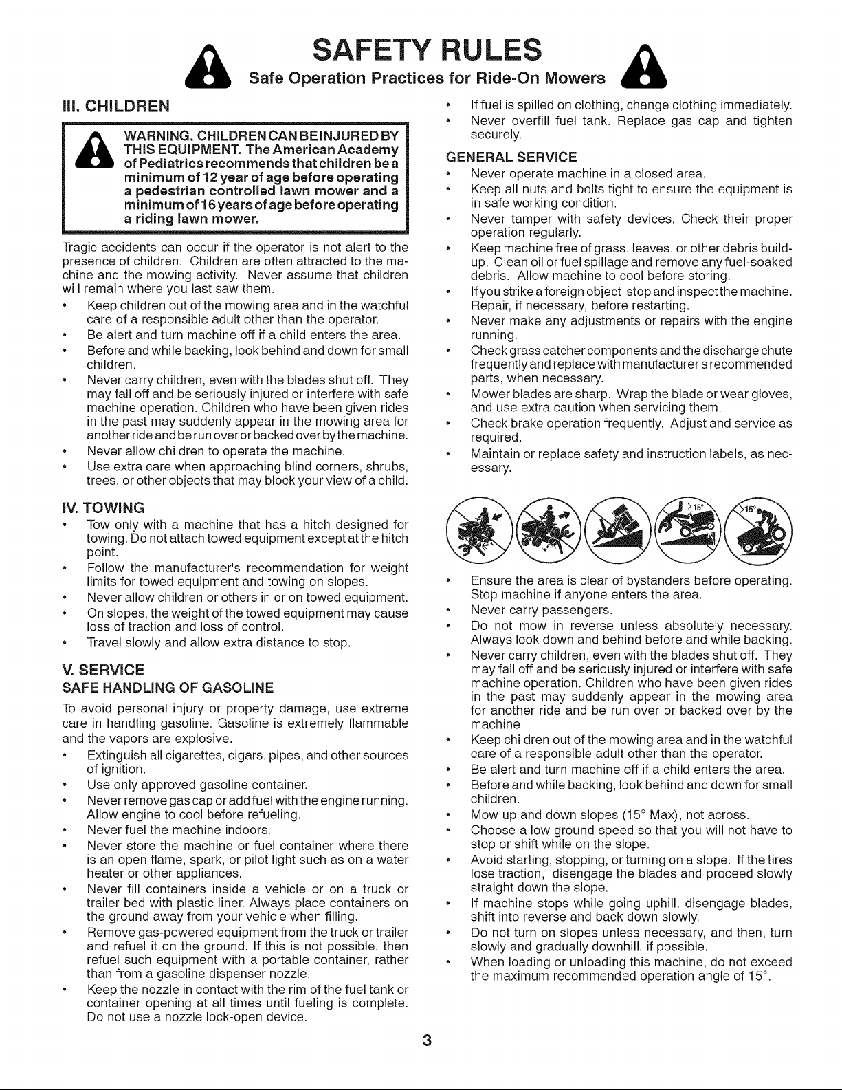
Safe Operation Practices for Ride=On Mowers
SAFETY RULES &
ill. CHILDREN
THIS EQUIPMENT. The American Academy
WARNING. CHILDRENCANBEINJUREDBY
of Pediatrics recommends that children be a
minimum of 12 year of age before operating
a pedestrian controlled lawn mower and a
minimum of 16years of age before operating
a riding lawn mower.
Tragic accidents can occur if the operator is not alert to the
presence of children. Children are often attracted to the ma-
chine and the mowing activity. Never assume that children
will remain where you last saw them.
• Keep children out of the mowing area and in the watchful
care of a responsible adult other than the operator.
• Be alert and turn machine off if a child enters the area.
• Before and while backing, look behind and down for small
children.
• Never carry children, even with the blades shut off. They
may fall off and be seriously injured or interfere with safe
machine operation. Children who have been given rides
in the past may suddenly appear in the mowing area for
another ride and be run over or backed over bythe machine.
• Never allow children to operate the machine.
• Use extra care when approaching blind corners, shrubs,
trees, or other objects that may block your view of a child.
• If fuel is spilled on clothing, change clothing immediately.
• Never overfill fuel tank. Replace gas cap and tighten
securely.
GENERAL SERVICE
• Never operate machine in a closed area.
• Keep all nuts and bolts tight to ensure the equipment is
in safe working condition.
• Never tamper with safety devices. Check their proper
operation regularly.
• Keep machine free of grass, leaves, or other debris build-
up. Clean oil or fuel spillage and remove any fuel-soaked
debris. Allow machine to cool before storing.
• Ifyou strike aforeign object, stop and inspect the machine.
Repair, if necessary, before restarting.
• Never make any adjustments or repairs with the engine
running.
• Check grass catcher components and the discharge chute
frequently and replace with manufacturer's recommended
parts, when necessary.
• Mower blades are sharp. Wrap the blade or wear gloves,
and use extra caution when servicing them.
• Check brake operation frequently. Adjust and service as
required.
• Maintain or replace safety and instruction labels, as nec-
essary.
iV. TOWING
• Tow only with a machine that has a hitch designed for
towing. Do not attach towed equipment except at the hitch
point.
• Follow the manufacturer's recommendation for weight
limits for towed equipment and towing on slopes.
• Never allow children or others in or on towed equipment.
• On slopes, the weight of the towed equipment may cause
loss of traction and loss of control.
• Travel slowly and allow extra distance to stop.
V. SERVICE
SAFE HANDLING OF GASOLINE
To avoid personal injury or property damage, use extreme
care in handling gasoline. Gasoline is extremely flammable
and the vapors are explosive.
• Extinguish all cigarettes, cigars, pipes, and other sources
of ignition.
• Use only approved gasoline container.
• Never remove gas cap or add fuel with the engine running.
Allow engine to cool before refueling.
• Never fuel the machine indoors.
• Never store the machine or fuel container where there
is an open flame, spark, or pilot light such as on a water
heater or other appliances.
• Never fill containers inside a vehicle or on a truck or
trailer bed with plastic liner. Always place containers on
the ground away from your vehicle when filling.
• Remove gas-powered equipment from the truck or trailer
and refuel it on the ground. If this is not possible, then
refuel such equipment with a portable container, rather
than from a gasoline dispenser nozzle.
• Keep the nozzle in contact with the rim of the fuel tank or
container opening at all times until fueling is complete.
Do not use a nozzle lock-open device.
• Ensure the area is clear of bystanders before operating.
Stop machine if anyone enters the area.
• Never carry passengers.
• Do not mow in reverse unless absolutely necessary.
Always look down and behind before and while backing.
• Never carry children, even with the blades shut off. They
may fall off and be seriously injured or interfere with safe
machine operation. Children who have been given rides
in the past may suddenly appear in the mowing area
for another ride and be run over or backed over by the
machine.
• Keep children out of the mowing area and in the watchful
care of a responsible adult other than the operator.
• Be alert and turn machine off if a child enters the area.
• Before and while backing, look behind and down for small
children.
• Mow up and down slopes (15 ° Max), not across.
• Choose a low ground speed so that you will not have to
stop or shift while on the slope.
• Avoid starting, stopping, or turning on a slope. If the tires
lose traction, disengage the blades and proceed slowly
straight down the slope.
• If machine stops while going uphill, disengage blades,
shift into reverse and back down slowly.
• Do not turn on slopes unless necessary, and then, turn
slowly and gradually downhill, if possible.
• When loading or unloading this machine, do not exceed
the maximum recommended operation angle of 15°.
3
PRODUCT SPECiFiCATiONS
Gasoline Capacity 3 Gallons
and type: Unleaded Regular
Oil Type (API-SG-SL): SAE 30 (above 32°F)
SAE 5W30 (below 32°F)
Oil Capacity: W/Filter: 64 oz
W/O Filter: 60 oz
Spark Plug: Champion RC12YC
(Gap: .030")
Charging System: 16 AMPS @ 3600 RPM
Battery: AMP/HR: 28
MIN. CCA: 230
Case Size: U1R
Blade Bolt Torque: 45-55 FT. LBS.
CONGRATULATIONS on your purchase of a new tractor.
It has been designed, engineered and manufactured to give
you the best possible dependability and performance.
Should you experience any problem you cannot easily rem-
edy, please contact your nearest authorized servicecenter/
department We have competent, well-trained technicians
and the proper tools to service or repair this tractor.
Please read and retain this manual. The instructions will
enable you to assemble and maintain your tractor properly.
Always observe the "SAFETY RULES".
CONGRATULATIONS on your purchase of a new tractor.
It has been designed, engineered and manufactured to
give you the best possible dependability and performance.
Should you experience any problem you cannot easily
remedy, please contact your nearest authorized service
center/department. We have competent, well-trained techni-
cians and the proper tools to service or repair this tractor.
Please read and retain this manual. The instructions will
enable you to assemble and maintain your tractor properly.
Always observe the "SAFETY RULES".
CUSTOMER RESPONSIBILITIES
• Read and observe the safety rules.
• Follow a regular schedule in maintaining, caring for
and using your tractor.
• Follow the instructions under "Maintenance" and "Stor-
age" sections of this manual.
• Wear proper Personal Protective Equipment (PPE)
while operating this machine, including (at aminimum)
sturdy footwear, eye protection, and hearing protection.
Do not mow in short and/or, open toed footwear.
• Always let someone know you are outside mowing.
WARNING: This tractor isequipped with an internal com-
bustion engine and should not be used on or near any un-
improved forest-covered, brush-covered or grass-covered
land unless the engine's exhaust system is equipped with
a spark arrester meeting applicable local or state laws (if
any). If a spark arrester is used, itshould be maintained
in effective working order by the operator.
A spark arrester for the muffler is available through your
nearest authorized service center/department.
In the state of California the above is required by law
(Section 4442 of the California Public Resources Code).
Other states may have similar laws. Federal laws apply
on federal lands.
TABLE OF CONTENTS
SAFETY RULES ......................................................... 2=3
PRODUCT SPECIFICATIONS ....................................... 4
CUSTOMER RESPONSIBILITIES ................................. 4
ASSEMBLY ................................................................. 6=9
OPERATION ........................................................... 10-16
MAINTENANCE SCHEDULE ...................................... 17
MAINTENANCE ..................................................... 17=20
SERVICE AND ADJUSTMENTS ............................ 21=25
STORAGE .................................................................... 26
TROUBLESHOOTING ............................................ 27=28
WARRANTY ................................................................. 30
ESPANOL .................................................................... 31
4
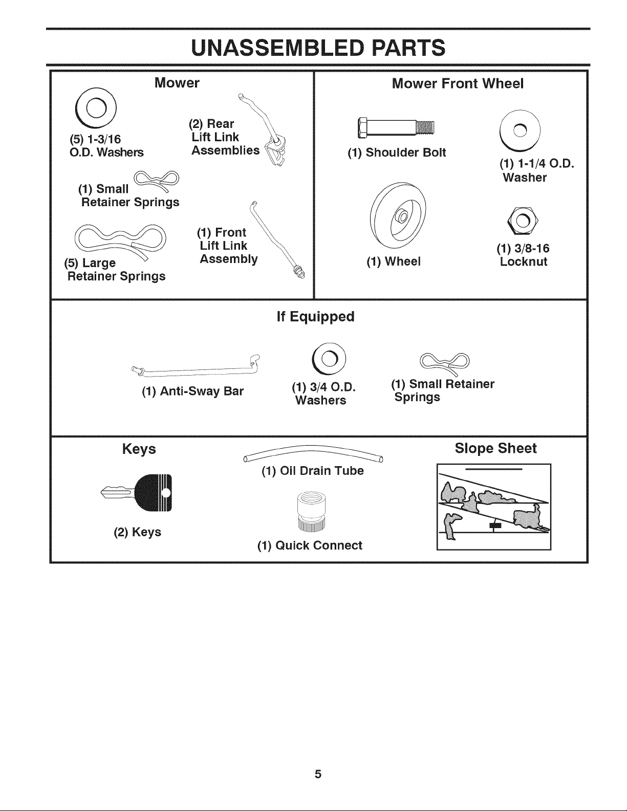
UNASSEMBLED PARTS
(5) 1-3/16
O.D. Washers
(1) Small
Retainer Springs
(5) Large
Retainer Springs
Mower
(2) Rear
Lift Link
Assemblies
(1) Front
Lift Link
Assembly
If Equipped
Mower Front Wheel
G
(1) Shoulder Bolt
(1) Wheel
(1) 1-1/40.D.
Washer
(1)3/8-16
Locknut
(1) Anti-Sway Bar
Keys
(2) Keys
(1)3/40.D.
Washers
(1) Oil Drain Tube
(1) Quick Connect
(1) Small Retainer
Springs
Slope Sheet
5
ASSEMBLY
Your new tractor has been assembled at the factory with exception of those parts left unassembled for shipping purposes.
To ensure safe and proper operation of your tractor all parts and hardware you assemble must be tightened securely. Use
the correct tools as necessary to ensure proper tightness.
TOOLS REQUIRED FOR ASSEMBLY
A socket wrench set will make assembly easier. Standard
wrench sizes are listed.
(2) 7/16" wrenches Utility knife
(1) 1/2" wrench Tire pressure gauge
(1) 3/4" wrench Pliers
(1) 3/4" socket w/drive ratchet
(1) 9/16" wrench Flashlight
When right or lefthand ismentioned in this manual, it means
when you are in the operating position (seated behind the
steering wheel).
TO REMOVE TRACTOR FROM CARTON
UNPACK CARTON
Remove all accessible loose parts and parts cartons
from carton.
• Remove end panels and lay side panels flat.
• Remove mower and packing materials.
• Check for any additional loose parts or cartons and
remove.
BEFORE REMOVING TRACTOR FROM
SKID
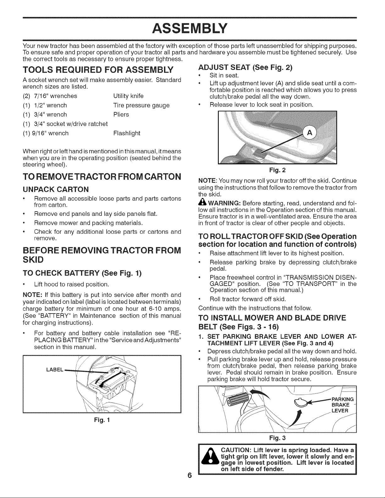
TO CHECK BATTERY (See Fig. 1)
Lift hood to raised position.
NOTE: If this battery is put into service after month and
year indicated on label (label is located between terminals)
charge battery for minimum of one hour at 6-10 amps.
(See "BATTERY" in Maintenance section of this manual
for charging instructions).
• For battery and battery cable installation see "RE-
PLACING BATTERY"in the "Service and Adjustments"
section in this manual.
ADJUST SEAT (See Fig. 2)
• Sit in seat.
• Lift up adjustment lever (A) and slide seat until a com-
fortable position is reached which allows you to press
clutch/brake pedal all the way down.
• Release lever to lock seat in position.
Fig. 2
NOTE: You may now roll your tractor off the skid. Continue
using the instructions that follow to remove the tractor from
the skid.
_f_ WARNING: Before starting, read, understand and fol-
low all instructions in the Operation section of this manual.
Ensure tractor is in awell-ventilated area. Ensure the area
in front of tractor is clear of other people and objects.
TO ROLLTRACTOR OFF SKID (See Operation
section for location and function of controls)
• Raise attachment lift lever to its highest position.
• Release parking brake by depressing clutch/brake
pedal.
• Place freewheel control in "TRANSMISSION DISEN-
GAGED" position. (See "TO TRANSPORT" in the
Operation section of this manual.)
• Roll tractor forward off skid.
Continue with the instructions that follow.
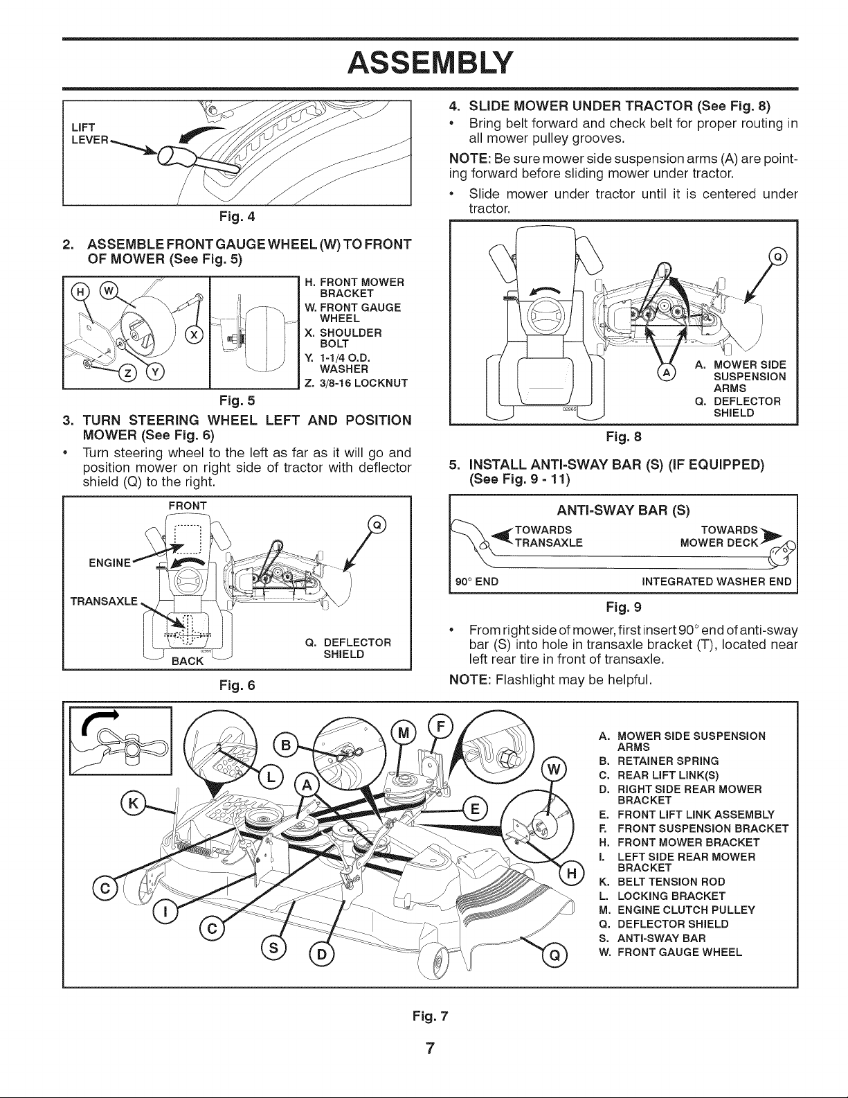
TO INSTALL MOWER AND BLADE DRIVE
BELT (See Figs. 3 - 16)
1. SET PARKING BRAKE LEVER AND LOWER AT=
TACHMENT LIFT LEVER (See Fig. 3 and 4)
• Depress clutch/brake pedal all the way down and hold.
• Pull parking brake lever up and hold, release pressure
from clutch/brake pedal, then release parking brake
lever. Pedal should remain in brake position. Ensure
parking brake will hold tractor secure.
Fig. 1
\/
Fig. 3
CAUTION: Lift lever is spring loaded. Have a
tight grip on lift lever, lower it slowly and en=
gage in lowest position. Lift lever is located
on left side of fender.
6
ASSEMBLY
LiFT
Fig. 4
=
ASSEMBLE FRONT GAUGE WHEEL (W) TO FRONT
OF MOWER (See Fig. 5)
H. FRONT MOWER
BRACKET
W. FRONT GAUGE
WHEEL
X. SHOULDER
BOLT
Y. 1=1/40.D.
WASHER
Z. 3/8=18 LOCKNUT
Fig. 5
=
TURN STEERING WHEEL
MOWER (See Fig. 6)
e
Turn steering wheel to the left as far as it will go and
position mower on right side of tractor with deflector
shield (Q) to the right.
FRONT
LEFT AND POSITION
4. SLIDE MOWER UNDER TRACTOR (See Fig. 8)
• Bring belt forward and check belt for proper routing in
all mower pulley grooves.
NOTE: Be sure mower side suspension arms (A) are point-
ing forward before sliding mower under tractor.
Slide mower under tractor until it is centered under
tractor.
A. MOWER SiDE
SUSPENSION
ARMS
Q. DEFLECTOR
SHIELD
Fig. 8
5=
INSTALL ANTI=SWAY BAR (S) (IF EQUIPPED)
(See Fig. 9 =11)
ANTI=SWAY BAR (S)
TOWARDS TOWARDS'h,.
TRANSAXLE.
Fig. 6
Q. DEFLECTOR
SHIELD
TRANSAXLE MOWER DECKY_
90° END INTEGRATED WASHER END
Fig. 9
From right side of mower, first insert90°end of anti-sway
bar (S) into hole in transaxle bracket (T), located near
left rear tire in front of transaxle.
NOTE: Flashlight may be helpful.
A. MOWER SIDE SUSPENSION
ARMS
B. RETAINER SPRING
C. REAR LIFT LINK(S)
D. RIGHT SIDE REAR MOWER
BRAC KET
E. FRONT LIFT LINK ASSEMBLY
F. FRONT SUSPENSION BRACKET
H. FRONT MOWER BRACKET
I. LEFT SIDE REAR MOWER
BRACKET
K. BELT TENSION ROD
L. LOCKING BRACKET
M. ENGINE CLUTCH PULLEY
Q. DEFLECTOR SHIELD
S. ANTI-SWAY BAR
W. FRONT GAUGE WHEEL
Fig. 7
7
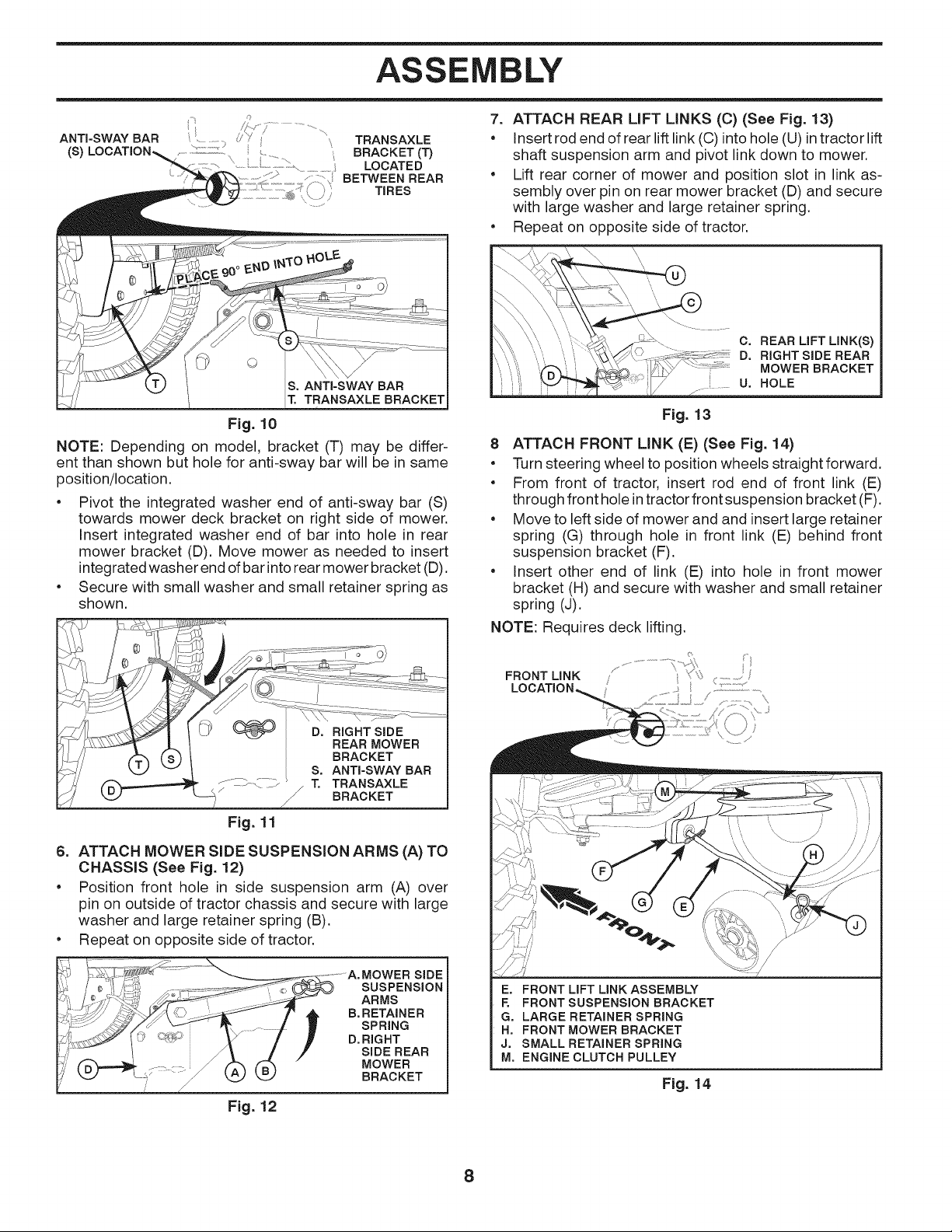
ASSEMBLY
ANTI-SWAY BAR
(s)
...................................... BRACKET (T)
......\
TRANSAXLE
.........../_ iii BETWEEN REAR
TRANSAXLE BRACKET
LOCATED
TIRES
Fig. 10
NOTE: Depending on model, bracket (T) may be differ-
ent than shown but hole for anti-sway bar will be in same
position/location.
• Pivot the integrated washer end of anti-sway bar (S)
towards mower deck bracket on right side of mower.
Insert integrated washer end of bar into hole in rear
mower bracket (D). Move mower as needed to insert
integrated washer end of bar into rear mower bracket (D).
• Secure with small washer and small retainer spring as
shown.
7. ATTACH REAR LiFT LINKS (C) (See Fig. 13)
• Insert rod end of rear lift link (C) into hole (U) intractor lift
shaft suspension arm and pivot link down to mower.
• Lift rear corner of mower and position slot in link as-
sembly over pin on rear mower bracket (D) and secure
with large washer and large retainer spring.
• Repeat on opposite side of tractor.
I\_ \\', " " _\ _, _\.. C. REAR LiFT LINK(S)
I" ",'_' D, RIGHT SiDE REAR
::i ..... MOWERBRACKET
,/ u. HOLE
Fig. 13
8 ATTACH FRONT LINK (E) (See Fig. 14)
• Turn steering wheel to position wheels straightforward.
• From front of tractor, insert rod end of front link (E)
through front hole in tractor front suspension bracket (F).
• Move to left side of mower and and insert large retainer
spring (G) through hole in front link (E) behind front
suspension bracket (F).
• Insert other end of link (E) into hole in front mower
bracket (H) and secure with washer and small retainer
spring (J).
NOTE: Requires deck lifting.
Fig. 11
6. ATTACH MOWER SIDE SUSPENSION ARMS (A) TO
CHASSIS (See Fig. 12)
• Position front hole in side suspension arm (A) over
pin on outside of tractor chassis and secure with large
washer and large retainer spring (B).
• Repeat on opposite side of tractor.
SUSPENSION
ARMS
B, RETAINER
SPRING
D, RIGHT
SIDE REAR
MOWER
BRACKET
Fig. 12
FRONT LINK
LOCATION,
E, FRONT LIFT LINK ASSEMBLY
F. FRONT SUSPENSION BRACKET
G. LARGE RETAINER SPRING
H, FRONT MOWER BRACKET
J. SMALL RETAINER SPRING
M, ENGINE CLUTCH PULLEY
Fig. 14
8
ASSEMBLY
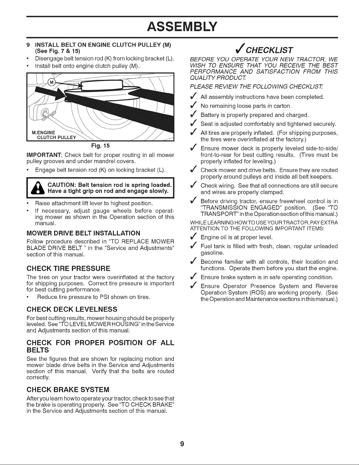
9 iNSTALL BELT ON ENGINE CLUTCH PULLEY (M)
(See Fig. 7 & 15)
• Disengage belt tension rod (K)from locking bracket (L).
• Install belt onto engine clutch pulley (M).
M.ENGINE
CLUTCH PULLEY
Fig. 15
iMPORTANT: Check belt for proper routing in all mower
pulley grooves and under mandrel covers.
• Engage belt tension rod (K) on locking bracket (L).
i CAUTION: Belt tension rod is spring loaded. 1
_ill Have a tight grip on rod and engage slowly.
• Raise attachment lift lever to highest position.
• If necessary, adjust gauge wheels before operat-
ing mower as shown in the Operation section of this
manual.
MOWER DRIVE BELT INSTALLATION
Follow procedure described in "TO REPLACE MOWER
BLADE DRIVE BELT " in the "Service and Adjustments"
section of this manual.
CHECK TIRE PRESSURE
The tires on your tractor were overinflated at the factory
for shipping purposes. Correct tire pressure is important
for best cutting performance.
• Reduce tire pressure to PSI shown on tires.
CHECK DECK LEVELNESS
For best cutting results, mower housing should be properly
leveled. See "TO LEVEL MOWER HOUSING" inthe Service
and Adjustments section of this manual.
'CHECKLIST
BEFORE YOU OPERATE YOUR NEW TRACTOR, WE
WtSH TO ENSURE THAT YOU RECEIVE THE BEST
PERFORMANCE AND SATISFACTION FROM THIS
QUALITY PRODUCT.
PLEASE REVIEW THE FOLLOWING CHECKLIS_
J" All assembly instructions have been completed.
J" No remaining loose parts in carton.
J" Battery is properly prepared and charged.
J" Seat is adjusted comfortably and tightened securely.
J" All tires are properly inflated. (For shipping purposes,
the tires were overinflated at the factory.)
J" Ensure mower deck is properly leveled side-to-side/
front-to-rear for best cutting results. (Tires must be
properly inflated for leveling.)
J" Check mower and drive belts. Ensure they are routed
properly around pulleys and inside all belt keepers.
J" Check wiring. See that all connections are still secure
and wires are properly clamped.
J" Before driving tractor, ensure freewheel control is in
"TRANSMISSION ENGAGED" position. (See "TO
TRANSPORT" in the Operation section ofthis manual.)
WHILELEARNINGHOWTO USEYOURTRACTOR,PAYEXTRA
ATTENTIONTO THE FOLLOWING IMPORTANTITEMS:
J" Engine oil is at proper level.
J" Fuel tank is filled with fresh, clean, regular unleaded
gasoline.
J" Become familiar with all controls, their location and
functions. Operate them before you start the engine.
J" Ensure brake system is in safe operating condition.
J" Ensure Operator Presence System and Reverse
Operation System (ROS) are working properly. (See
the Operation and Maintenance sections inthis manual.)
CHECK FOR PROPER POSITION OF ALL
BELTS
See the figures that are shown for replacing motion and
mower blade drive belts in the Service and Adjustments
section of this manual. Verify that the belts are routed
correctly.
CHECK BRAKE SYSTEM
After you learn how to operate your tractor, check to see that
the brake is operating properly. See "TO CHECK BRAKE"
in the Service and Adjustments section of this manual.
9
OPERATION
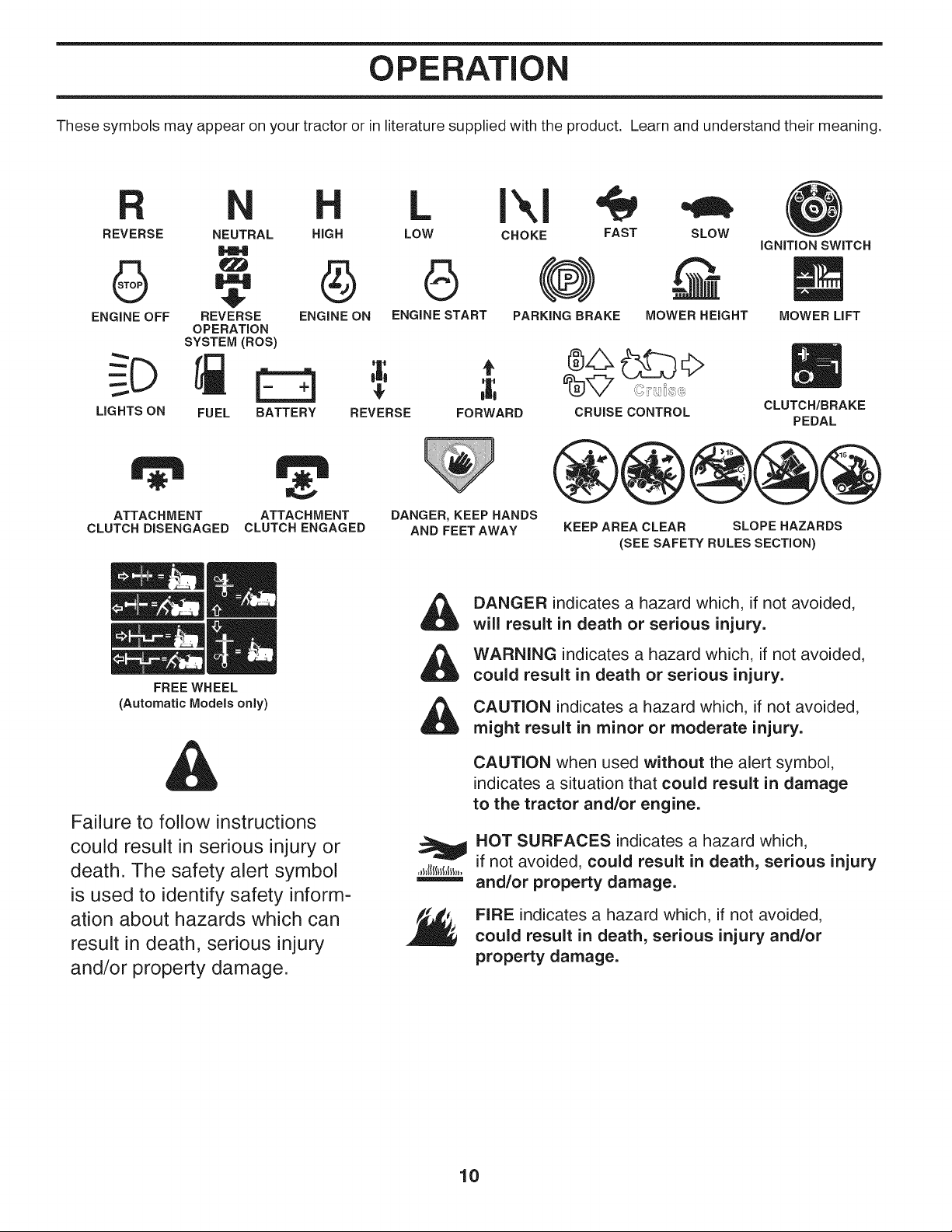
These symbols may appear on your tractor or in literature supplied with the product. Learn and understand their meaning.
L I\1
LOW CHOKE FAST SLOWREVERSE NEUTRAL HIGH
IGNITION SWITCH
ENGINE OFF REVERSE ENGINE ON ENGINE START PARKING BRAKE MOWER HEIGHT
LIGHTS ON
ATTACH MENT
CLUTCH DISENGAGED
(Automatic Models only)
Failure to follow instructions
could result in serious injury or
death. The safety alert symbol
is used to identify safety inform-
ation about hazards which can
result in death, serious injury
and/or property damage.
OPERATION
SYSTEM (ROS)
FUEL BATTERY
FREE WHEEL
ATTACH MENT
CLUTCH ENGAGED
REVERSE FORWARD CRUISE CONTROL
DANGER, KEEP HANDS
AND FEET AWAY
&
&
&
DANGER indicates a hazard which, if not avoided,
will result in death or serious injury.
WARNING indicates a hazard which, if not avoided,
could result in death or serious injury.
CAUTION indicates a hazard which, if not avoided,
might result in minor or moderate injury.
CAUTION when used without the alert symbol,
indicates a situation that could result in damage
to the tractor and/or engine.
HOT SURFACES indicates a hazard which,
if not avoided, could result in death, serious injury
and/or property damage.
FIRE indicates a hazard which, if not avoided,
could result in death, serious injury and/or
property damage.
KEEP AREA CLEAR SLOPE HAZARDS
(SEE SAFETY RULES SECTION)
MOWER LIFT
m
CLUTCH/BRAKE
PEDAL
10
OPERATION
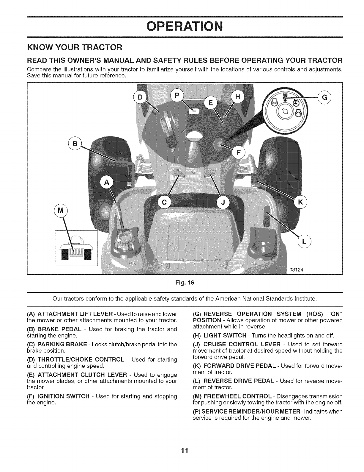
KNOW YOUR TRACTOR
READ THiS OWNER'S MANUAL AND SAFETY RULES BEFORE OPERATING YOUR TRACTOR
Compare the illustrations with your tractor to familiarize yourself with the locations of various controls and adjustments.
Save this manual for future reference.
Our tractors conform to the applicable safety standards of the American National Standards Institute.
(A) ATTACHMENT LIFT LEVER - Used to raise and lower
the mower or other attachments mounted to your tractor.
(B) BRAKE PEDAL - Used for braking the tractor and
starting the engine.
(C) PARKING BRAKE - Locks clutch/brake pedal intothe
brake position.
(D) THROTTLE/CHOKE CONTROL - Used for starting
and controlling engine speed.
(E) ATTACHMENT CLUTCH LEVER - Used to engage
the mower blades, or other attachments mounted to your
tractor.
(F) IGNITION SWITCH - Used for starting and stopping
the engine.
03124
Fig. 16
(G) REVERSE OPERATION SYSTEM (ROS) "ON"
POSITION - Allows operation of mower or other powered
attachment while in reverse.
(H) LIGHT SWITCH - Turns the headlights on and off.
(J) CRUISE CONTROL LEVER - Used to set forward
movement of tractor at desired speed without holding the
forward drive pedal.
(K) FORWARD DRIVE PEDAL - Used for forward move-
ment of tractor.
(L) REVERSE DRIVE PEDAL - Used for reverse move-
ment of tractor.
(M) FREEWHEEL CONTROL - Disengages transmission
for pushing or slowly towing the tractor with the engine off.
(P) SERVICE REMINDER/HOUR METER- Indicates when
service is required for the engine and mower.
11
OPERATION
The operation of any tractor can result in foreign objects thrown into the eyes, which can result
in severe eye damage. Always wear safety glasses or eye shields while operating your tractor
or performing any adjustments or repairs. We recommend standard safety glasses or a wide
vision safety mask worn over spectacles.
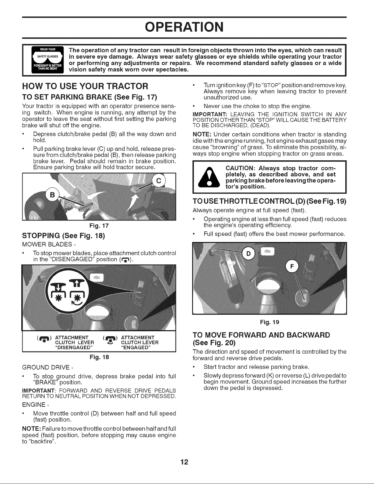
HOW TO USE YOUR TRACTOR
TO SET PARKING BRAKE (See Fig. 17)
Your tractor is equipped with an operator presence sens-
ing switch. When engine is running, any attempt by the
operator to leave the seat without first setting the parking
brake will shut off the engine.
• Depress clutch/brake pedal (B) all the way down and
hold.
Pull parking brake lever (C) up and hold, release pres-
sure from clutch/brake pedal (B), then release parking
brake lever. Pedal should remain in brake position.
Ensure parking brake will hold tractor secure.
Fig. 17
STOPPING (See Fig. 18)
MOWER BLADES -
• Tostop mower blades, place attachment clutch control
in the "DISENGAGED" position (t_).
• Turn ignitionkey (F) to "STOP"position and remove key.
Always remove key when leaving tractor to prevent
unauthorized use.
• Never use the choke to stop the engine.
IMPORTANT: LEAVING THE IGNITION SWITCH IN ANY
POSITION OTHER THAN "STOP" WILL CAUSE THE BATTERY
TO BE DISCHARGED, (DEAD).
NOTE: Under certain conditions when tractor is standing
idle with the engine running, hot engine exhaust gases may
cause "browning" of grass. To eliminate this possibility, al-
ways stop engine when stopping tractor on grass areas.
CAUTION: Always stop tractor corn=
pletely, as described above, and set
parking brake before leaving the opera=
tor's position.
TO USE TH ROTTLE CONTROL (D) (See Fig. 19)
Always operate engine at full speed (fast).
• Operating engine at less than full speed (fast) reduces
the engine's operating efficiency.
• Full speed (fast) offers the best mower performance.
(_) ATTACHMENT (I_) ATTACHMENT
CLUTCH LEVER CLUTCH LEVER
"DISENGAGED .... ENGAGED"
Fig. 18
GROUND DRIVE -
• To stop ground drive, depress brake pedal into full
"BRAKE" position.
IMPORTANT: FORWARD AND REVERSE DRIVE PEDALS
RETURNTO NEUTRALPOSITION WHEN NOT DEPRESSED.
ENGINE -
• Move throttle control (D) between half and full speed
(fast) position.
NOTE: Failure to move throttle control between half and full
speed (fast) position, before stopping may cause engine
to "backfire".
Fig. 19
TO MOVE FORWARD AND BACKWARD
(See Fig. 20)
The direction and speed of movement is controlled by the
forward and reverse drive pedals.
• Start tractor and release parking brake.
• Slowly depress forward (K) or reverse (L) drive pedal to
begin movement. Ground speed increases the further
down the pedal is depressed.
12
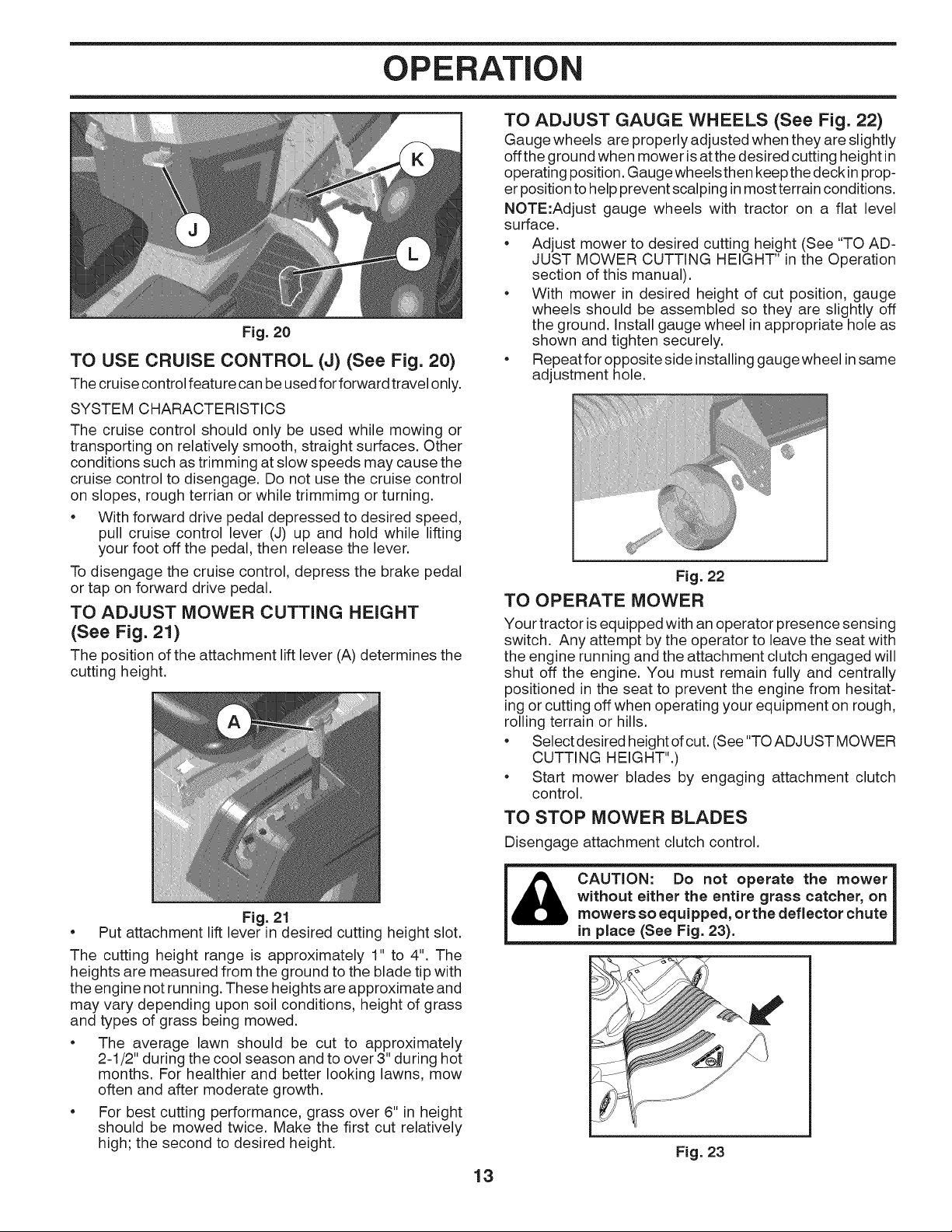
OPERATION
Fig. 20
TO USE CRUISE CONTROL (J) (See Fig. 20)
The cruise control feature can be used for forward travel only.
SYSTEM CHARACTERISTICS
The cruise control should only be used while mowing or
transporting on relatively smooth, straight surfaces. Other
conditions such as trimming at slow speeds may cause the
cruise control to disengage. Do not use the cruise control
on slopes, rough terrian or while trimmimg or turning.
• With forward drive pedal depressed to desired speed,
pull cruise control lever (J) up and hold while lifting
your foot off the pedal, then release the lever.
To disengage the cruise control, depress the brake pedal
or tap on forward drive pedal.
TO ADJUST MOWER CUTTING HEIGHT
(See Fig. 21)
The position of the attachment lift lever (A) determines the
cutting height.
TO ADJUST GAUGE WHEELS (See Fig. 22)
Gauge wheels are properly adjusted when they are slightly
off the ground when mower isat the desired cutting height in
operating position. Gauge wheels then keep thedeck inprop-
er position tohelp prevent scalping in most terrain conditions.
NOTE:Adjust gauge wheels with tractor on a flat level
surface.
• Adjust mower to desired cutting height (See "TO AD-
JUST MOWER CUTTING HEIGHT" in the Operation
section of this manual).
• With mower in desired height of cut position, gauge
wheels should be assembled so they are slightly off
the ground. Install gauge wheel in appropriate hole as
shown and tighten securely.
• Repeat for opposite side installing gauge wheel in same
adjustment hole.
Fig. 22
TO OPERATE MOWER
Your tractor isequipped with an operator presence sensing
switch. Any attempt by the operator to leave the seat with
the engine running and the attachment clutch engaged will
shut off the engine. You must remain fully and centrally
positioned in the seat to prevent the engine from hesitat-
ing or cutting off when operating your equipment on rough,
rolling terrain or hills.
• Select desired height of cut. (See "TO ADJUST MOWER
CUTTING HEIGHT".)
• Start mower blades by engaging attachment clutch
control.
TO STOP MOWER BLADES
Disengage attachment clutch control.
• Put attachment lift lever in desired cutting height slot.
Fig. 21
The cutting height range is approximately 1" to 4". The
heights are measured from the ground to the blade tip with
the engine not running. These heights are approximate and
may vary depending upon soil conditions, height of grass
and types of grass being mowed.
• The average lawn should be cut to approximately
2-1/2" during the cool season and to over 3" during hot
months. For healthier and better looking lawns, mow
often and after moderate growth.
• For best cutting performance, grass over 6" in height
should be mowed twice. Make the first cut relatively
high; the second to desired height.
_ CAUTION: Do not operate the mower
without either the entire grass catcher, on
mowers so equipped, or the deflector chute
in place (See Fig. 23).
'If......
Fig. 23
13
OPERATION
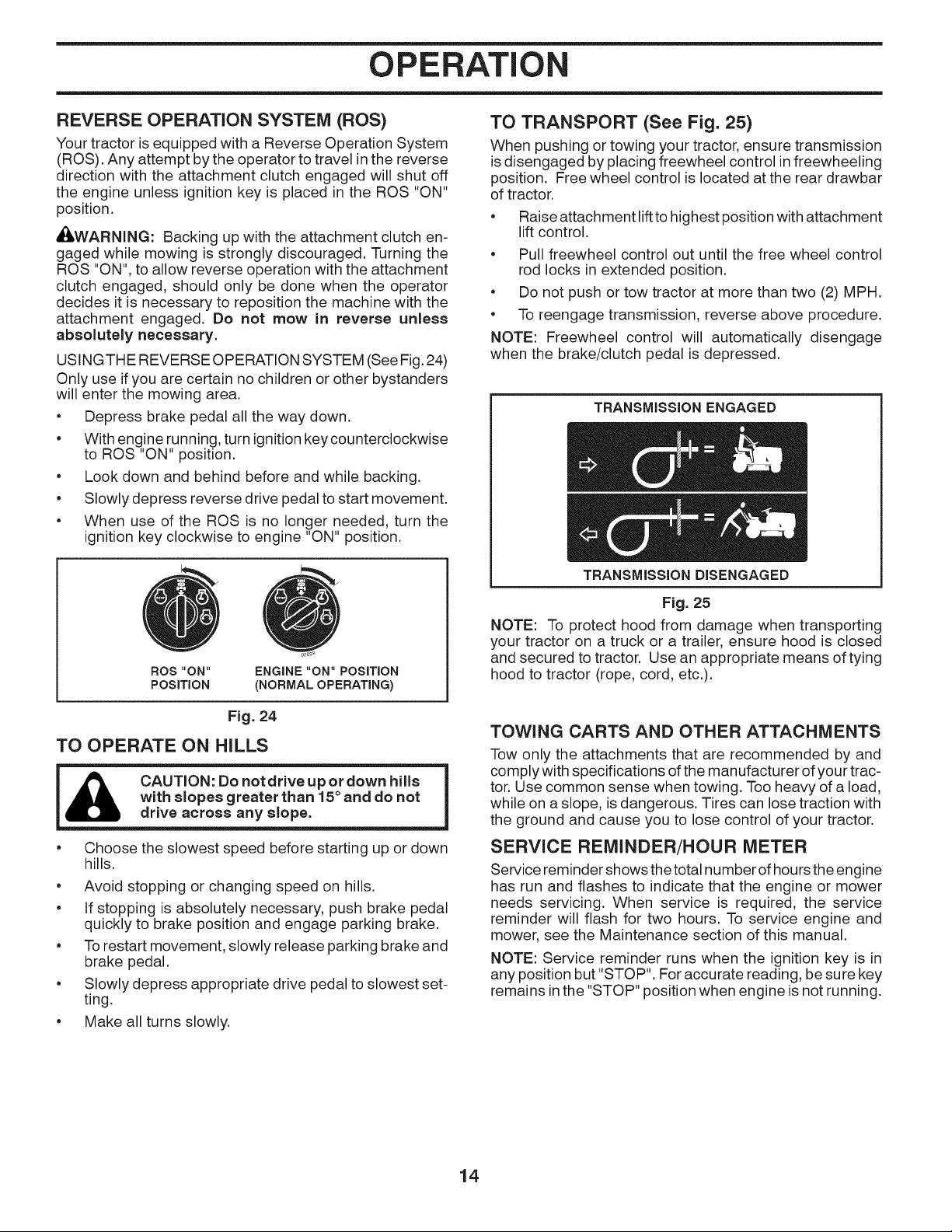
REVERSE OPERATION SYSTEM (ROS)
Your tractor is equipped with a Reverse Operation System
(ROS). Any attempt by the operator to travel in the reverse
direction with the attachment clutch engaged will shut off
the engine unless ignition key is placed in the ROS "ON"
position.
_WARNING: Backing up with the attachment clutch en-
gaged while mowing is strongly discouraged. Turning the
ROS "ON", to allow reverse operation with the attachment
clutch engaged, should only be done when the operator
decides it is necessary to reposition the machine with the
attachment engaged. Do not mow in reverse unless
absolutely necessary.
USINGTHE REVERSE OPERATION SYSTEM (See Fig. 24)
Only use if you are certain no children or other bystanders
will enter the mowing area.
• Depress brake pedal all the way down.
• With engine running, turn ignitionkey counterclockwise
to ROS "ON" position.
• Look down and behind before and while backing.
• Slowly depress reverse drive pedal to start movement.
• When use of the ROS is no longer needed, turn the
ignition key clockwise to engine "ON" position.
TO TRANSPORT (See Fig. 25)
When pushing or towing your tractor, ensure transmission
is disengaged by placing freewheel control in freewheeling
position. Free wheel control is located at the rear drawbar
of tractor.
• Raise attachment lift to highest position with attachment
lift control.
• Pull freewheel control out until the free wheel control
rod locks in extended position.
• Do not push or tow tractor at more than two (2) MPH.
• To reengage transmission, reverse above procedure.
NOTE: Freewheel control will automatically disengage
when the brake/clutch pedal is depressed.
TRANSMISSION ENGAGED
ROS "ON" ENGINE "ON" POSITION
POSITION (NORMAL OPERATING)
Fig. 24
TO OPERATE ON HILLS
CAUTION: Do not drive up or down hills
with slopes greater than 15° and do not
drive across any slope.
• Choose the slowest speed before starting up or down
hills.
• Avoid stopping or changing speed on hills.
• If stopping is absolutely necessary, push brake pedal
quickly to brake position and engage parking brake.
• Torestart movement, slowly release parking brake and
brake pedal.
• Slowly depress appropriate drive pedal to slowest set-
ting.
• Make all turns slowly.
TRANSMiSSiON DISENGAGED
Fig. 25
NOTE: To protect hood from damage when transporting
your tractor on a truck or a trailer, ensure hood is closed
and secured to tractor. Use an appropriate means of tying
hood to tractor (rope, cord, etc.).
TOWING CARTS AND OTHER ATTACHMENTS
Tow only the attachments that are recommended by and
comply with specifications of the manufacturer of your trac-
tor. Use common sense when towing. Too heavy of a load,
while on aslope, is dangerous. Tires can lose traction with
the ground and cause you to lose control of your tractor.
SERVICE REMINDER/HOUR METER
Service reminder shows the total number of hours the engine
has run and flashes to indicate that the engine or mower
needs servicing. When service is required, the service
reminder will flash for two hours. To service engine and
mower, see the Maintenance section of this manual.
NOTE: Service reminder runs when the ignition key is in
any position but "STOP". For accurate reading, be sure key
remains inthe "STOP" position when engine is not running.
14
OPERATION
BEFORE STARTING THE ENGINE
CHECK ENGINE OiL LEVEL
The engine in your tractor has been shipped from the fac-
tory already filled with summer weight oil.
• Check engine oil with tractor on level ground.
• Remove oil fill cap/dipstick and wipe clean, reinsert the
dipstick and screw cap tight, wait for a few seconds,
remove and read oil level. If necessary, add oil until
"FUL!/' mark on dipstick is reached. Do not overfill.
• For cold weather operation you should change oil for
easier starting. (See "OI L VISCOSITY CHART" inthe
Maintenance section of this manual.)
• To change engine oil, see the Maintenance section in
this manual.
ADD GASOLINE
• Fill fuel tank to bottom of filler neck. Do not overfill.
Use fresh, clean, regular gasoline with a minimum of
87 octane. Do not mix oil with gasoline. Purchase fuel
in quantities that can be used within 30 days to ensure
fuel freshness.
fuel. Do not store, spill or use gasoline
CAUTION: Wipe off any spilled oil or
near an open flame.
IMPORTANT: WHEN OPERATING IN TEMPERATURES
BELOW32°F (0°C), USE FRESH, CLEAN WINTER GRADE
GASOLINE TO HELP ENSURE GOOD COLD WEATHER
STARTING.
CAUTION: Alcohol blended fuels (called gasohol
or using ethanol or methanol) can attract moisture
which leads to separation and formation of acids
during storage. Acidic gas can damage the fuel
system of an engine while in storage. To avoid
engine problems, the fuel system should be emptied
before storage of 30 days or longer. Drain the gas
tank, start the engine and let it run until the fuel
lines and carburetor are empty. Use fresh fuel next
season. See Storage Instructions for additional
information. Never use engine or carburetor cleaner
products in the fuel tank or permanent damage may
occur. Fuel stabilizer is an acceptable alternative
in minimizing the formation of fuel gum deposits
during storage. Add stabilizer to gasoline in fuel
tank or storage container. Always follow the mix
ratio found on stabilizer container. Run engine at
least 10 minutes after adding stabilizer to allow the
stabilizer to reach the carburetor. Do not empty
the gas tank and carburetor if using fuel stabilizer.
TO START ENGINE (See Fig. 16)
When starting the engine for the first time or if the engine
has run out of fuel, itwill take extra cranking time to move
fuel from the tank to the engine.
• Be sure freewheel control is in the transmission en-
gaged position.
• Sit on seat in operating position, depress brake pedal
and set parking brake.
• Move attachment clutch to "DISENGAGED" position.
• Move throttle control to choke position.
NOTE: Before starting, read the warm and cold starting
procedures below.
• Insert key intoignition and turn key clockwise to"START"
position and release key as soon as engine starts.
Do not run starter continuously for more than fifteen
seconds per minute. If the engine does not start after
several attempts, move throttle control to fast position,
wait a few minutes and try again. If engine still does
not start, move the throttle control back to the choke
position and retry.
WARM WEATHER STARTING (50°F/10°C and above)
• When engine starts, move the throttle control to the
fast position.
• The attachments and ground drive can now be used. If
the engine does not accept the load, restart the engine
and allow itto warm up for one minute using the choke
as described above.
COLD WEATHER STARTING (50°F/10°C and below)
• When engine starts, allow engine to run with the
throttle control in the choke position until the engine
runs roughly, then move throttle control to fast posi-
tion. This may require an engine warm-up period from
several seconds to several minutes, depending on the
temperature.
AUTOMATIC TRANSMISSION WARM UP
• Before driving the unit incold weather, the transmission
should be warmed up as follows:
• Be sure the tractor is on level ground.
• Release the parking brake and let the brake slowly
return to operating position.
• Allow one minute for transmission to warm up. This
can be done during the engine warm up period.
• Theattachmentscanalso beusedduringtheenginewarm-
up period after the transmission has been warmed up.
15
OPERATION
MOWING TIPS
• DO NOT use tire chains when the mower housing is
attached to tractor.
• Mower should be properly leveled for best mowing
performance. See "TO LEVEL MOWER HOUSING"
in the Service and Adjustments section of this manual.
• The left hand side of mower should be used for trimming.
• Drive so that clippings are discharged onto the area
that has been cut. Have the cut area to the right of
the tractor. This will result in a more even distribution
of clippings and more uniform cutting.
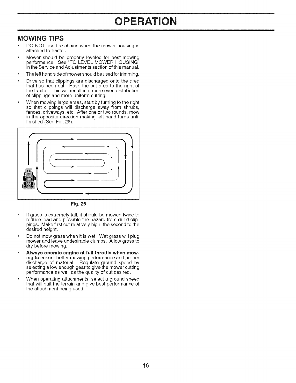
• When mowing large areas, start by turning to the right
so that clippings will discharge away from shrubs,
fences, driveways, etc. After one or two rounds, mow
in the opposite direction making left hand turns until
finished (See Fig. 26).
}=
(
Fig. 26
• If grass is extremely tall, itshould be mowed twice to
reduce load and possible fire hazard from dried clip-
pings. Make first cut relatively high; the second to the
desired height.
• Do not mow grass when it iswet. Wet grass will plug
mower and leave undesirable clumps. Allow grass to
dry before mowing.
• Always operate engine at full throttle when mow=
ing to ensure better mowing performance and proper
discharge of material. Regulate ground speed by
selecting a low enough gear to give the mower cutting
performance as well as the quality of cut desired.
• When operating attachments, select a ground speed
that will suit the terrain and give best performance of
the attachment being used.
16
MAINTENANCE
MAINTENANCE
SCHEDULE
Check BrakeOperation
Check Tire Pressure
T Check Operator Presence & ROS Systems
A Check for Loose Fasteners
C ChecWReplace Mower Blades
T Lubrication Chart
0 Check Battery Level
R Clean Battery andTerminals
Clean Debris Off Steering Plate
Check Mower Levelness
Check V-Belts
Check Engine Oil Level
Change Engine Oil (models with oil filter)
Change Engine Oil (models without oil filter)
NE Clean Air Filter
G Clean Air Screen
Inspect Muffler/Spark Arrester
N Replace Oil Filter (If equipped)
E Clean Engine Cooling Fins
Replace Spark Plug
Replace Air FilterPaper Cartridge
m R_lace Fuel Filter
1 - Change more often when operating under a heavy load or in high ambient temperatures.
2 - Service more often when operating in dirty or dusty conditions.
BEFORE
EACH
USE
v"
v"
v"
v"
EVERY
8
HOURS
EVERY
25
HOURS
EVERY
50
HOURS
v"
v"
_#1,2
V"2
v"2
v"
3 - Replace blades more often when mowing in sandy soil.
4 - Not required if equipped with maintenance-free battery.
EVERY
100
HOURS
EVERY
SEASON
v'
v'
v"
5 - See Cleaning in Maintenance Section.
BEFORE
STORAGE
v"
v"
v"
V"
v"
GENERAL RECOMMENDATIONS
The warranty on this tractor does not cover items that have
been subjected to operator abuse or negligence. Toreceive
full value from the warranty, operator must maintain tractor
as instructed in this manual.
Some adjustments will need to be made periodically to
properly maintain your tractor.
At least once a season, check to see if you should make
any of the adjustments described in the Service and
Adjustments section of this manual.
• At least once a year you should replace the spark plug,
clean or replace air filter, and check blades and belts
for wear. A new spark plug and clean air filter ensure
proper air-fuel mixture and help your engine run better
and last longer.
BEFORE EACH USE
• Check engine oil level.
• Check brake operation.
• Check tire pressure.
• Check operator presence and ROS systems for proper
operation.
• Check for loose fasteners.
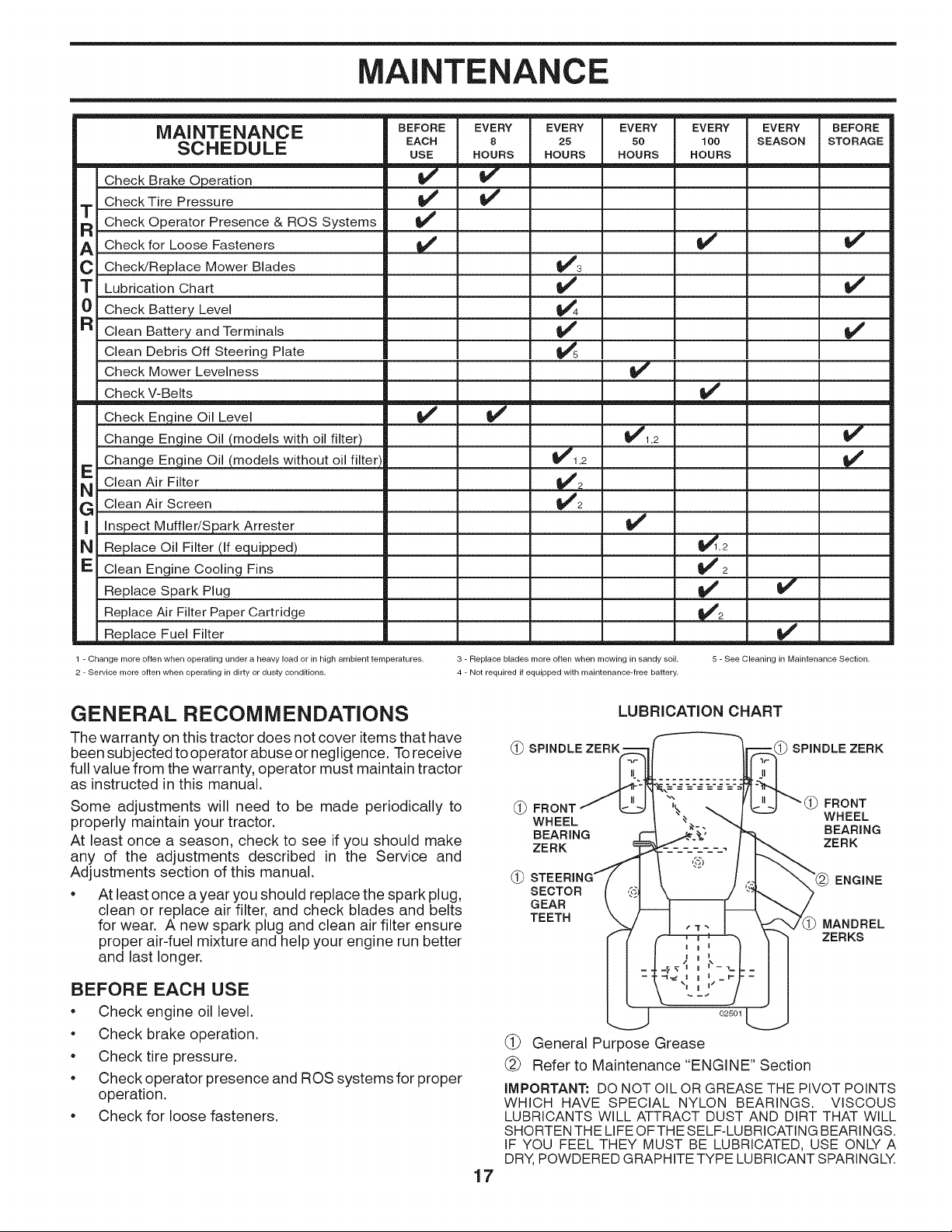
LUBRICATION CHART
(_ SPINDLE ZERK = SPINDLE ZERK
(_ FRONT FRONT
WHEEL WHEEL
BEARING BEARING
ZERK ZERK
SECTOR
GEAR
TEETH
02501
(_ General Purpose Grease
(_ Refer to Maintenance "ENGINE" Section
IMPORTANT: DO NOT OIL OR GREASE THE PIVOT POINTS
WHICH HAVE SPECIAL NYLON BEARINGS. VISCOUS
LUBRICANTS WILL ATTRACT DUST AND DIRT THAT WILL
SHORTEN THE LIFE OFTHE SELF-LUBRICATING BEARINGS.
IF YOU FEEL THEY MUST BE LUBRICATED, USE ONLY A
DRY, POWDERED GRAPHITE TYPE LUBRICANT SPARINGLY.
17
ENGINE
MANDREL
ZERKS
MAINTENANCE
TRACTOR
Always observe safety rules when performing any
maintenance.
BRAKE OPERATION
If tractor requires more than five (5) feet to stop at highest
speed in highest gear on a level, dry concrete or paved
surface, then brake must be checked and adjusted. (See
"TO CHECK BRAKE" in the Service and Adjustments
section of this manual).
TIRES
• Maintain proper air pressure in all tires (See the sides
of tires for proper PSI).
• Keep tires free of gasoline, oil, or insect control
chemicals which can harm rubber.
• Avoid stumps, stones, deep ruts, sharp objects and
other hazards that may cause tire damage.
NOTE: To seal tire punctures and prevent flat tires due
to slow leaks, tire sealant may be purchased from your
local parts dealer. Tire sealant also prevents tire dry rot
and corrosion.
OPERATOR PRESENCE SYSTEM AND REVERSE
OPERATION SYSTEM (ROS) (See Fig. 27)
Be sure operator presence and reverse operation systems
are working properly. If your tractor does not function as
described, repair the problem immediately.
• The engine should not start unless the brake pedal is
fully depressed, and the attachment clutch control is
in the disengaged position.
CHECK OPERATOR PRESENCE SYSTEM
• When the engine is running, any attempt bythe operator
to leave the seat without first setting the parking brake
should shut off the engine.
• When the engine is running and the attachment clutch
is engaged, any attempt by the operator to leave the
seat should shut off the engine.
• The attachment clutch should never operate unless
the operator is in the seat.
CHECK REVERSE OPERATION (ROS) SYSTEM
• When the engine is running with the ignition switch in
the engine "ON" position and the attachment clutch
engaged, any attempt by the operator to shift into
reverse should shut off the engine.
• When the engine is running with the ignition switch
in the ROS "ON" position and the attachment clutch
engaged, any attempt by the operator to shift into
reverse should NOT shut off the engine.
ROS "ON"
POSITION
ENGINE "ON" POSITION
(NORMAL OPERATING)
Fig. 27
BLADE CARE
Forbest results mower blades must be kept sharp. Replace
bent or damaged blades.
proved bythe manufacturer of your tractor.
_ CAUTION: Use onlya replacement blade ap=
Using a blade not approved by the manu=
facturer of your tractor is hazardous, could
damage your tractor and void your warranty.
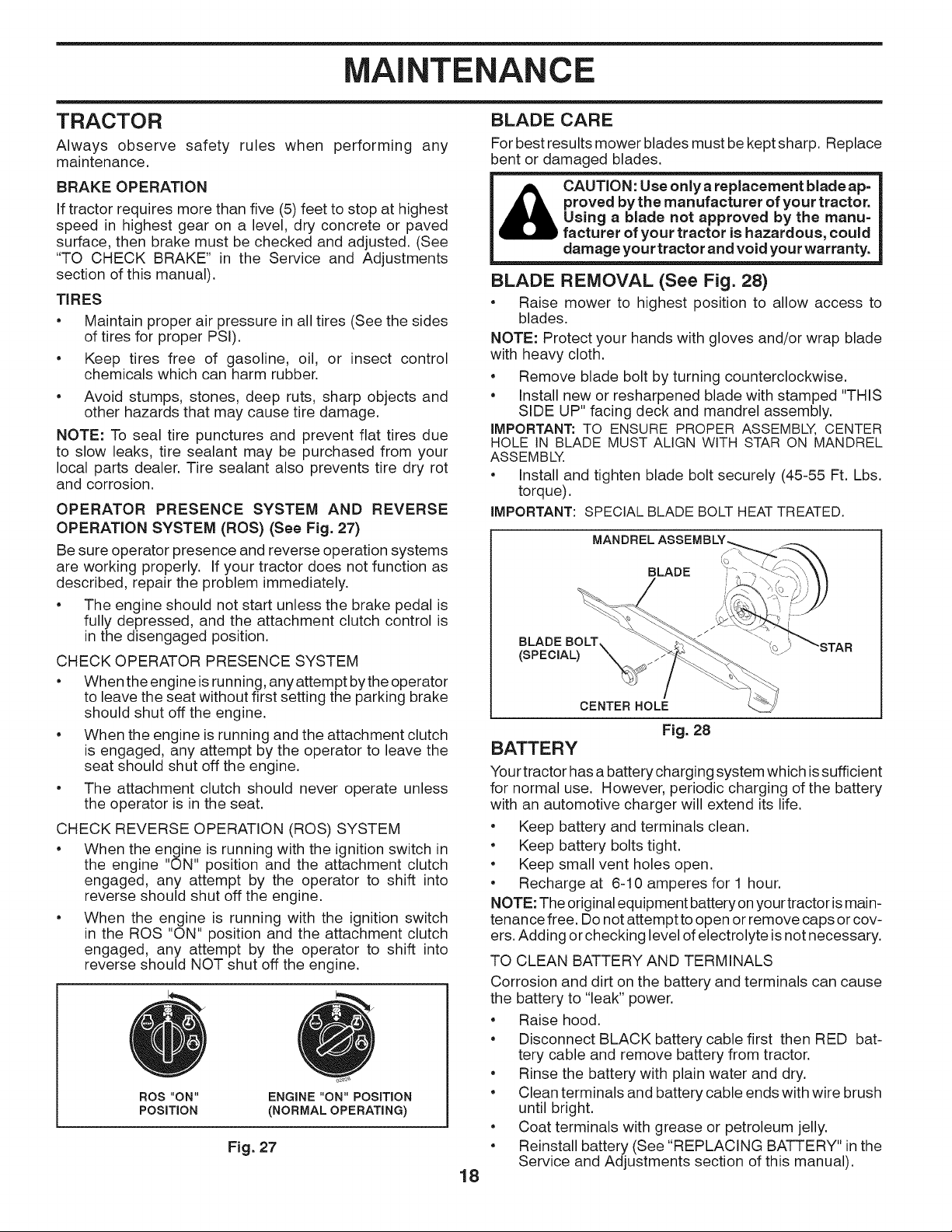
BLADE REMOVAL (See Fig. 28)
• Raise mower to highest position to allow access to
blades.
NOTE: Protect your hands with gloves and/or wrap blade
with heavy cloth.
• Remove blade bolt by turning counterclockwise.
• Install new or resharpened blade with stamped "THIS
SIDE UP" facing deck and mandrel assembly.
iMPORTANT: TO ENSURE PROPER ASSEMBLY, CENTER
HOLE IN BLADE MUST ALIGN WITH STAR ON MANDREL
ASSEMBLY.
• Install and tighten blade bolt securely (45-55 Ft. Lbs.
torque).
IMPORTANT: SPECIAL BLADE BOLTHEATTREATED.
MANDREL
BLADE
BLADE BOLT,
(SPECIAL)
CENTER HOLE
Fig. 28
BATTERY
Your tractor has a battery charging system which issufficient
for normal use. However, periodic charging of the battery
with an automotive charger will extend its life.
• Keep battery and terminals clean.
• Keep battery bolts tight.
• Keep small vent holes open.
• Recharge at 6-10 amperes for 1 hour.
NOTE: The original equipment battery on your tractor ismain-
tenance free. Do not attempt to open or remove caps or cov-
ers. Adding or checking level of electrolyte isnot necessary.
TO CLEAN BATTERY AND TERMINALS
Corrosion and dirt on the battery and terminals can cause
the battery to "leak" power.
• Raise hood.
• Disconnect BLACK battery cable first then RED bat-
tery cable and remove battery from tractor.
• Rinse the battery with plain water and dry.
• Clean terminals and battery cable ends with wire brush
until bright.
• Coat terminals with grease or petroleum jelly.
• Reinstall battery (See "REPLACING BATTERY" inthe
Service and Adjustments section of this manual).
18

MAINTENANCE
V=BELTS
Check V-belts for deterioration and wear after 100 hours
of operation and replace if necessary. The belts are not
adjustable. Replace belts if they begin to slip from wear.
TRANSAXLE MAINTENANCE
The transaxle was sealed at the factory and fluid mainte-
nance is not required for the life of the transaxle. Should
the transaxle ever leak or require servicing, contact your
nearest authorized service center/department.
ENGINE
LUBRICATION
Only use high quality detergent oil rated with API service
classification SG-SL. Select the oil's SAE viscosity grade
according to your expected operating temperature.
SAE VISCOSITY GRADES
,q
F -20 0 30 32 40 60 80 100
C -30 -2; -1; ; 1'0 20 30 4;
TEMPERATURE RANGE ANTICIPATED BEFORE NEXT OIL CHANGE
NOTE: Although multi-viscosity oils (5W30, 10W30 etc.
improve starting incold weather, they will result inincreased
oil consumption when used above 32°R Check your engine
oil level more frequently to avoid possible engine damage
from running low on oil.
Change the oil after every 50 hours of operation or at least
once a year if the tractor is not used for 50 hours inone year.
Check the crankcase oil level before starting the engine
and after each eight (8) hours of operation. Tighten oil fill
cap/dipstick securely each time you check the oil level.
TO CHANGE ENGINE OIL (See Fig. 29)
Determine temperature range expected before oil change.
All oil must meet API service classification SG-SL.
• Ensure tractor ison level surface.
• Oil will drain more freely when warm.
• Catch oil in a suitable container.
• Remove oil fill cap/dipstick. Be careful not to allow dirt
to enter the engine when changing oil.
• Remove yellow cap from end of drain valve and install
the drain tube onto the fitting.
OIL DRAIN VALVE
CLOSED
AND "-__...._ __(_---/,_'_ -" _'\
LOCKED --'_--___._._
POSITION __._
YELLOW CAP
Unlock drain valve by pushing inward and turning
counterclockwise.
• To open, pull out on the drain valve.
• After oil has drained completely, close and lock the
drain valve by pushing inward and turning clockwise
until the pin is in the locked position as shown.
• Remove the drain tube and replace the cap onto to the
bottom fitting of the drain valve.
• Refill engine with oil through oil fill dipstick tube. Pour
slowly. Do not overfill. For approximate capacity see
"PRODUCT SPECIFICATIONS" section of this manual.
Use gauge on oil fill cap/dipstick for checking level.
Ensure dipstick cap istightened securely for accurate
reading. Keep oil at "FULl" line on dipstick. Tighten
cap onto the tube securely when finished.
ENGINE OIL FILTER
Replace the engine oil filter every season or every other
oil change if the tractor is used more than 100 hours in
one year.
AIR FILTER
Your engine will not run properly using a dirty air filter.
Service air cleaner more often under dusty conditions.
See engine Manual.
CLEAN AIR SCREEN
The air screen is over the air intake blower located on top
of engine. The air screen must be kept free of dirt and
chaff to prevent engine damage from overheating. Clean
with a wire brush or compressed air to remove dirt and
stubborn dried gum fibers.
ENGINE COOLING SYSTEM
To ensure proper cooling, make sure the grass screen,
cooling fins, and other external surfaces of the engine are
kept clean at all times.
Every 100 hours of operation (more often under extremely
dusty, dirty conditions), remove the blower housing and
other cooling shrouds. Clean the cooling fins and external
surfaces as necessary. Ensure the cooling shrouds are
reinstalled.
NOTE: Operating the engine with a blocked grass screen,
dirty orplugged cooling fins, and/or cooling shrouds removed
will cause engine damage due to overheating.
MUFFLER
Inspect and replace corroded muffler and spark arrester (if
equipped) as it could create a fire hazard and/or damage.
SPARK PLUGS
Replace spark plugs at the beginning of each mowing
season or after every 100 hours of operation, whichever
occurs first. Spark plug type and gap setting are shown in
"PRODUCT SPECIFICATIONS" section of this manual.
Fig. 29
19

MAINTENANCE
IN=LINE FUEL FILTER (See Fig. 30)
The fuel filter should be replaced once each season. Iffuel
filter becomes clogged, obstructing fuel flow to carburetor,
replacement is required.
• With engine cool, removefilter andplugfuel linesections.
• Place new fuel filter in position in fuel line with arrow
pointing towards carburetor.
• Be sure there are no fuel line leaks and clamps are
properly positioned.
• Immediately wipe up any spilled gasoline.
CLAMP
I CLAMP __
FUEL FILTER _ J 00667
Fig. 30
CLEANING
e
Clean engine, battery, seat, finish, etc. of all foreign
matter.
e
Clean debris from steering plate. Debris can restrict
clutch/brake pedal shaft movement, causing belt slip
and loss of drive.
DECK WASHOUT PORT (See Fig. 32)
Your tractor's deck is equipped with a washout port as part
of its deck wash system. It should be utilized after each use.
1. Drive the tractor to a level, clear spot on your lawn, near
enough to a water spigot for your garden hose to reach.
IMPORTANT: Make certain the tractor's discharge chute is
directed AWAY from your house, garage, parked cars, etc.
Remove bagger chute or mulch cover if attached.
2. Make sure the attachment clutch control is in the
"DISENGAGED" position, set the parking brake, and
stop the engine.
3. Thread the nozzle adapter (packaged with your tractor's
Operator's Manual) onto the end of your garden hose.
4. Pull backthe lock collar of the nozzle adapter and push
the adapter onto the deck washout port at the left end
of the mower deck. Release the lock collar to lock the
adapter on the nozzle.
NOZZLE ADAPTER
I _ CAUTION: Avoid all pinch points and i
STEERING
STEERING SYSTEM, DASH, FENDER AND MOWER NOT SHOWN
movable parts.
...=.CLUTCH/BRAKE PEDAL D
CLEAN
TOP SIDE
\
Fig. 31
• Keep finished surfaces and wheels free of all gasoline,
oil, etc.
• Protect painted surfaces with automotive type wax.
Except for the washout port (if equipped), we do not
recommend using a garden hose or pressure washer to
clean the outside of your tractor unless the engine and
transmission are covered to keep water out. Water in
engine or transmission will shorten the useful life of your
tractor. Use compressed air or a leaf blower to remove
grass, leaves and trash from outside tractor and mower.
Fig. 32
IMPORTANT: Tug hose ensuring connection is secure.
5. Turn the water on.
6. While sitting in the operator's position on the tractor,
re-start the engine and place the throttle lever in the
Fast ",_" position.
IMPORTANT: Recheck the area to ensure the area isclear.
Ensure no children are inthe area while cleaning the deck.
7. Move the tractor's attachment clutch control to the
"ENGAGED" position. Remain in the operator's position
with the cutting deck engaged until the deck is cleaned.
8. Move the tractor's attachment clutch control to the
"DISENGAGED" position. Turn the ignition key to the
STOP position to turn the tractor's engine off. Turn the
water off.
9. Pull back the lock collar of the nozzle adapter to discon-
nect the adapter from the nozzle washout port.
10.Move the tractor to adry area, preferably a concrete or
paved area. Place the attachment clutch control in the
"ENGAGED" position to remove excess water and to
help dry before putting the tractor away.
fitting could expose you or others to
WARNING: A broken or missing washout
thrown objects from contact withthe blade.
• Replace broken or missing washout fitting
immediateJy, prior to using mower again.
• Plug any hoJes in mower with boJts and Iocknuts.
2O

SERVICE AND ADJUSTMENTS
Depress brake pedal fully and set parking brake.
WARNING: TO AVOID SERIOUS iNJURY, BEFORE PERFORMING ANY SERVICE OR ADJUSTMENTS:
" Place attachment clutch in "DISENGAGED" position.
" Turn ignition key to "STOP" and remove key.
" Make sure the blades and all moving parts have completely stopped.
" Disconnect spark plug wire from spark plug and place wirewhere itcannot come incontact with plug.
TO REMOVE MOWER (See Fig. 33)
• Place attachment clutch in "DISENGAGED" position.
• Lower attachment lift lever to its lowest position.
• Disengage belt tension rod (K) from lock bracket (L).
loaded. Have a tight grip on rodand
release slowly.
• Remove mower belt from electric clutch pulley (M).
• Disconnect front link (E) from mower - remove retainer
spring and washer.
• Goto eitherside ofmower anddisconnect mowersuspen-
sion arm (A) from chassis and rear lift link (C) from rear
mower bracket (D)- remove retainersprings andwashers.
• Go to other side of mower and disconnect the suspen-
sion arm and rear lift link.
CAUTION: After rear lift links are discon=
nected, the attachment lift lever will be
spring loaded. Have a tight grip on lift
lever when changing position of the lever.
From right side of mower, disconnect anti-sway bar (S)
from right rear mower bracket (D) - remove retainer
spring and washer and pull mower toward you until the
bar falls from the hole in bracket.
Turn tractor steering wheel to the left as far as itwill go.
Slide mower out from under right side of tractor.
TO INSTALL MOWER
Follow procedure described in "INSTALL MOWER AND
DRIVE BELT" in the Assembly section of this manual.
TO REPLACE MOWER BLADE DRIVE BELT
(See Fig. 34)
MOWER DRIVE BELT REMOVAL
• Park tractor on a level surface. Engage parking brake.
• Lower attachment lift lever to its lowest position.
• Disengage belt tension rod (K) from lock bracket (L).
loaded. Have a firm gripon rod and
release slowly. J
• Remove screws (P) from mandrel covers (Q) and
remove covers.
• Remove any dirt orgrass clippings which may have accu-
mulated around mandrels and entire upper decksurface.
• Remove belt from electric clutch pulley (M), both man-
drel pulleys (R) and all idler pulleys (V).
MOWER DRIVE BELT INSTALLATION
• Install belt around all mandrel pulleys (R) and around
idler pulleys (V) as shown.
• Install belt onto electric clutch pulley (M).
IMPORTANT: Check belt for proper routing in all mower
pulley grooves.
• Reassemble mandrel covers (Q). Securely tighten all
screws.
• Engage belt tension rod (K) on locking bracket (L).
&
• Raise attachment lift lever to highest position.
Fig. 33
Fig. 34
21

SERVICE AND ADJUSTMENTS
TO LEVEL MOWER
Make sure tires are properly inflated to the PSI shown on
tires. If tires are over or under inflated, it may affect the
appearance of your lawn and lead you to think the mower
is not adjusted properly.
VISUAL SIDE-TO-SIDE ADJUSTMENT (See Fig. 35)
• With all tires properly inflated and ifyour lawn appears
unevenly cut, determine which side of mower iscutting
lower.
NOTE: As desired, you can raise the low side of mower
or lower the high side.
• Go to side of mower you wish to adjust.
• With a 3/4" or adjustable wrench, turn lift link adjust-
ment nut (A) to the left to lower the mower, or, to the
right to raise the mower.
Turnnut right Turnnut left
to raise mower to lower mower
Fig. 35
NOTE: Each full turn of adjustment nut will change mower
height about 3/16".
• Test your adjustment by mowing some uncut grass
and visually checking the appearance. Readjust, if
necessary, until you are satisfied with the results.
PRECISION SIDE-TO-SIDE ADJUSTMENT (See Fig. 36)
• With all tires properly inflated, park tractor on level
ground or driveway.
• Ifadjustment is necessary, see steps inVisual Adjust-
ment instructionsabove.
• Recheck measurements, adjust if necessary until both
sides are equal.
FRONT-TO-BACK ADJUSTMENT (See Figs. 37 & 38)
iMPORTANT: Deck must be level side-to-side.
Toobtain the best cutting results, the mower blades should
be adjusted so the front tip is 1/8" to 1/2" lower than the
rear tip when the mower is in its highest position.
your hands with gloves and/or wrap
_ CAUTION: Blades are sharp. Protect
e
Raise mower to highest position.
e
Position any blade so the tip is pointing straightforward.
blade with heavy cloth.
Measure distance (B) to the ground at front and rear
tip of the blade.
Fig. 37
If front tip of blade is not 1/8" to 1/2" lower than the
rear tip, go to the front of tractor.
With an 11/16" or adjustable wrench, loosen jam nut
A several turns to clear adjustment nut B.
With a 3/4" or adjustable wrench, turn front link adjust-
ment nut (B) clockwise (4_)(tighten) to raise the front
of mower, or, counterclockwise (F-,)(loosen) to lower
the front mower.
i_ CAUTION: Blades are sharp. Protect
e
Raise mower to its highest position.
e
At both sides of mower, position blade at side and
your hands with gloves and/or wrap
blade with heavy cloth.
measure the distance (A) from bottom edge of blade
to the ground. The distance should be the same on
both sides.
Fig. 36
TIGHTEN ADJUST LOOSEN
NUT B TO RAISE ADJUST NUT
MOWER _z --- B TO LOWER
LOOSEN JAM NUTA FIRST
MOWER
Fig. 38
NOTE: Each full turn of the adjustment nut will change
mower height about 1/8".
• Recheck measurements, adjust if necessary until front
tip of blade is 1/8" to 1/2" lower than the rear tip.
• Hold adjustment nut inposition with wrench and tighten
jam nut securely against adjustment nut.
22

SERVICE AND ADJUSTMENTS
TO REPLACE MOTION DRIVE BELT
(See Fig. 39)
Park the tractor on level surface. Engage parking brake.
For assistance, there is a belt installation guide decal on
bottom side of left footrest.
BELT REMOVAL -
1. Remove mower. (See "TO REMOVE MOWER" section
in this manual.)
NOTE: Observe entire motion drive belt and position of all
belt guides and keepers.
2. Remove belt from stationary idler (A) and clutching
idler (B).
3. Remove belt from centerspan idler (C).
4. Pull belt slack toward rear of tractor. Remove belt
upwards from transaxle input pulley (D).
5. Remove belt downward from engine pulley (E).
6. Slide belt toward rear of tractor, off the steering plate
(F) and remove from tractor.
BELT INSTALLATION -
1. Install new belt from tractor rear to front, over the steer-
ing plate (F) and above clutch brake pedal shaft (G).
2. Pull belt toward front of tractor and roll belt onto engine
pulley (E).
3. Pullbelt toward rearoftractor. Carefully work belt down
around transaxle input pulley (D). Be sure belt is inside
the belt keeper.
4. Install belt on centerspan idler (C).
5. Install belt through stationary idler (A) and clutching
idler (B).
6. Make sure belt is in all pulley grooves and inside all
belt guides and keepers.
7. Install mower. (See "TO INSTALL MOWER" section in
this manual.)
TO CHECK BRAKE
If tractor requires more than five (5) feet to stop at highest
speed in highest gear on a level, dry concrete or paved
surface, then brake must be serviced.
You may also check brake by:
1. Park tractor on a level, dry concrete or paved surface,
depress brake pedal all the way down and engage
parking brake.
.
Disengage transmission by placing freewheel control
in "transmission disengaged" position. Pull freewheel
control out and into the slot and release so it isheld in
the disengaged position.
The rear wheels must lock and skid when you try to manu-
ally push the tractor forward. If the rear wheels rotate,
then the brake needs to be serviced. Contact a qualified
service center.
FRONT WHEEL TOE=IN/CAMBER
Your new tractor front wheel toe-in and camber isset at the
factory and is normal. The front wheel toe-in and camber
are not adjustable. If damage has occurred to affect the
factory set front wheel toe-in or camber, contact a qualified
service center.
TO REMOVE WHEEL (See Fig. 40)
• Block up axle securely.
• Remove axle cover, retaining ring and washers to allow
wheel removal (rear wheel contains a square key - Do
not lose).
• Repair tire and reassemble.
• On rear wheels only: align grooves in rear wheel hub
and axle. Insert square key.
• Replace washers and snap retaining ring securely in
axle groove.
• Replace axle cover.
NOTE: To seal tire punctures and prevent flat tires due
to slow leaks, tire sealant may be purchased from your
local parts dealer. Tire sealant also prevents tire dry rot
and corrosion.
Fig. 39
WASHERS
RETAINING
AXLE COVER
SQUARE KEY (RE_ I
WHEEL ONLY)
Fig. 40
23

SERVICE AND ADJUSTMENTS
TO START ENGINE WiTH A WEAK BATTERY
(See Fig. 41)
WARNING: Lead=acid batteries gen=
erate explosive gases. Keep sparks,
flame and smoking materials away from
batteries. Always wear eye protection
when around batteries.
If your battery is too weak to start the engine, itshould be
recharged. (See "BATTERY" in the MAINTENANCE sec-
tion of this manual).
If "jumper cables" are used for emergency starting, follow
this procedure:
IMPORTANT: YOUR TRACTOR IS EQUIPPED WITH A 12
VOLTSYSTEM. THE OTHER VEHICLE MUSTALSO BE A 12
VOLTSYSTEM. DO NOTUSEYOUR TRACTOR BATTERYTO
STARTOTHER VEHICLES.
TO ATTACH JUMPER CABLES -
• Connect one end of the RED cable to the POSITIVE
(+) terminal of each battery(A-B), taking care not to
short against tractor chassis.
• Connect one end ofthe BLACK cable to the NEGATIVE
(-) terminal (C) of fully charged battery.
• Connect the other end of the BLACK cable (D) to good
chassis ground, away from fuel tank and battery.
TO REMOVE CABLES, REVERSE ORDER -
• BLACK cable first from chassis and then from the fully
charged battery.
• RED cable last from both batteries.
REPLACING BATTERY (See Fig. 42)
nals by allowing a wrench or any other
_ WARNING: Do notshort batterytermi=
• Lift hood to raised position.
• Remove terminal cover.
• Disconnect BLACK battery cable then RED battery
cable and carefully remove battery from tractor.
• Install new battery with terminals in same position as
old battery.
• Reinstall terminal cover.
• First connect RED battery cable to positive (+) battery
terminal with bolt and nut as shown. Tighten securely.
• Connect BLACKgrounding cable to negative (-) battery
terminal with remaining bolt and nut. Tighten securely
• Close hood.
object to contact both terminals at the
same time. Before connecting battery,
remove metal bracelets, wristwatch
bands, rings, etc. Positive terminal
must be connected first to prevent
sparking from accidental grounding.
WEAK OR DEAD FULLY CHARGED
BATTERY BATTERY
Fig. 41
Fig. 42
24

SERVICE AND ADJUSTMENTS
TO REPLACE HEADLIGHT BULB
Raise hood.
• Pull bulb holder out of the hole in the backside of the
grill.
• Replace bulb in holder and push bulb holder securely
back into the hole in the backside of the grill.
• Close hood.
iNTERLOCKS AND RELAYS
Loose or damaged wiring may cause your tractor to run
poorly, stop running, or prevent it from starting.
• Check wiring.
TO REPLACE FUSE
Replace with 20 amp automotive-type plug-in fuse. The
fuse holder is located behind the dash.
TO REMOVE HOOD AND GRILL ASSEMBLY
(See Fig. 43)
• Raise hood.
• Unsnap headlight wire connector.
• Stand in front of tractor. Grasp hood at sides, tilt toward
engine and lift off of tractor.
• To replace, reverse above procedure.
ENGINE
TO ADJUST THROTTLE CONTROL CABLE
The throttle control has been preset at the factory and
adjustment should not be necessary. If adjustment is nec-
essary, see engine manual.
TO ADJUST CHOKE CONTROL
The choke control has been preset atthe factory and adjust-
ment should not be necessary. If adjustment is necessary,
see engine manual.
04010
HOOD
HEADLIGHT WIRE
CONNECTOR
Fig. 43
25

STORAGE
Immediately prepare your tractor for storage at the end
of the season or if the tractor will not be used for 30 days
or more.
WARNIN G: Never store the tractor with
gasoline in the tank inside a building
where fumes may reach an open flame
or spark. Allowthe engine to cool before
storing in any enclosure.
TRACTOR
Remove mowerfrom tractor forwinter storage. When mower
isto bestored for aperiod oftime, clean itthoroughly, remove
all dirt, grease, leaves, etc. Store in a clean, dry area.
• Clean entire tractor (See "CLEANING" in the Mainte-
nance section of this manual).
• Inspect and replace belts, if necessary (See belt re-
placement instructions inthe Service and Adjustments
section of this manual).
• Lubricate as shown in the Maintenance section of this
manual.
• Be sure that all nuts, bolts and screws are securely
fastened. Inspect moving parts for damage, breakage
and wear. Replace if necessary.
• Touch up all rusted or chipped paint surfaces; sand
lightly before painting.
BATTERY
• Fully charge the battery for storage.
• After a period of time in storage, battery may require
recharging.
• To help prevent corrosion and power leakage during
long periods of storage, battery cables should be dis-
connected and battery cleaned thoroughly (see "TO
CLEAN BATTERY AND TERMINALS" in the Mainte-
nance section of this manual).
• After cleaning, leave cables disconnected and place
cables where they cannot come in contact with battery
terminals.
• If battery is removed from tractor for storage, do not
store battery directly on concrete or damp surfaces.
ENGINE
FUEL SYSTEM
IMPORTANT: IT IS IMPORTANTTO PREVENT GUM DEPOSITS
FROM FORMING IN ESSENTIAL FUELSYSTEM PARTS SUCH
AS CARBURETOR, FUEL FILTER, FUEL HOSE, OR TANK
DURING STORAGE. ALSO, EXPERIENCE INDICATES THAT
ALCOHOL BLENDED FUELS (CALLED GASOHOL OR USING
ETHANOLOR METHANOL) CAN ATTRACT MOISTURE WHICH
LEADS TO SEPARATION AND FORMATION OFACIDS DURING
STORAGE. ACIDIC GAS CAN DAMAGE THE FUEL SYSTEM
OF AN ENGINE WHILE IN STORAGE.
• Empty the fuel tank by starting the engine and let it run
until the fuel lines and carburetor are empty.
• Never use engine or carburetor cleaner products in the
fuel tank or permanent damage may occur.
• Use fresh fuel next season.
NOTE: Fuel stabilizer is an acceptable alternative in mini-
mizing the formation of fuel gum deposits during storage.
Add stabilizer to gasoline in fuel tank or storage container.
Always follow the mix ratio found on stabilizer container.
Run engine at least 10 minutes after adding stabilizer to
allow the stabilizer to reach the carburetor. Do not empty
the gas tank and carburetor if using fuel stabilizer.
ENGINE OIL
Drain oil (with engine warm) and replace with clean en-
gine oil. (See "ENGINE" in the Maintenance section of
this manual).
CYLINDER(S)
• Remove spark plug(s).
• Pour one ounce of oil through spark plug hole(s) into
cylinder(s).
• Turn ignition key to "START" position for a few seconds
to distribute oil.
• Replace with new spark plug(s).
OTHER
• Do not store gasoline from one season to another.
• Replace your gasoline can if your can starts to rust.
Rust and/or dirt in your gasoline will cause problems.
• If possible, store your tractor indoors and cover it to
give protection from dust and dirt.
• Cover your tractor with a suitable protective cover that
does not retain moisture. Do not use plastic. Plastic
cannot breathe which allows condensation to form and
will cause your tractor to rust.
IMPORTANT: NEVERCOVERTRACTORWHILE ENGINEAND
EXHAUSTAREAS ARE STILLWARM.
26

TROUBLESHOOTING
PROBLEM
Will not start
Hard to start
Engine will not turn
over
CAUSE
1. Out of fuel.
2. Engine not "CHOKED" properly.
3. Engine flooded.
4. Bad spark plug.
5. Dirty air filter.
6. Dirty fuel filter.
7. Water in fuel.
8. Loose or damaged wiring.
9. Engine valves out of adjustment.
1. Dirty air filter.
2. Bad spark plug.
3. Weak or dead battery.
4. Dirty fuel filter.
5. Stale or dirty fuel.
6. Loose or damaged wiring.
7. Engine valves out of adjustment.
1. Brake pedal not depressed.
2. Attachment clutch is engaged.
3. Weak or dead battery.
4. Blown fuse.
5. Corroded battery terminals.
6. Loose or damaged wiring.
7. Faulty ignition switch.
8. Faulty solenoid or starter.
9. Faulty operator presence switch(es).
CORRECTION
2. See "TO START ENGINE" in Operation section.
3. Wait several minutes before attempting to start.
4. Replace spark plug.
5. Clean/replace air filter.
6. Replace fuel filter.
7. Empty fuel tank and carburetor, refill tank with fresh
gasoline and replace fuel filter.
8. Check all wiring.
9. Contact an authorized service center/department.
1. Clean/replace air filter.
2. Replace spark plug.
3. Recharge or replace battery.
4. Replace fuel filter.
5. Empty fuel tank and refill tank with fresh, clean gas.
6. Check all wiring.
7. Contact an authorized service center/department.
1. Depress brake pedal.
2. Disengage attachment clutch.
3. Recharge or replace battery.
4. Replace fuse.
5. Clean battery terminals.
6. Check all wiring.
7. Check/replace ignition switch.
8. Check/replace solenoid or starter.
9. Contact an authorized service center/department.
Engine clicks but
will not start
Loss of power
Excessive
vibration
1. Weak or dead battery.
2. Corroded battery terminals.
3. Loose or damaged wiring.
4. Faulty solenoid or starter.
1. Cutting too much grass/too fast.
2. Throttle in "CHOKE" position.
3. Build-up of grass, leaves, trash under mower.
4. Dirty air filter.
5. Low oil level/dirty oil.
6. Faulty spark plug.
7. Dirty fuel filter.
8. Stale or dirty fuel.
9. Water in fuel.
10. Spark plug wire loose.
11. Dirty engine air screen/fins.
12. Dirty/clogged muffler.
13. Loose or damaged wiring.
14. Engine valves out of adjustment.
1. Worn, bent or loose blade.
2. Bent blade mandrel.
3. Loose/damaged part(s).
1. Recharge or replace battery.
2. Clean battery terminals.
3. Check all wiring.
4. Check/replace solenoid or starter.
1. Raise cutting height/reduce speed.
2. Adjust throttle control.
3. Clean underside of mower housing.
4. Clean/replace air filter.
5. Check oil level/change oil.
6. Clean and regap or change spark plug.
7. Replace fuel filter.
8. Empty fuel tank and refill tank with fresh, clean gas.
9. Empty fuel tank and carburetor, refill tank with fresh
gasoline and replace fuel filter.
10. Connect and tighten spark plug wire.
11. Clean engine air screen/fins.
12. Clean/replace muffler.
13. Check all wiring.
14. Contact an authorized service center/department.
1. Replace blade. Tighten blade bolt.
2. Replace blade mandrel.
3. Tighten loose part(s). Replace damaged parts.
27

TROUBLESHOOTING
PROBLEM CORRECTION
Engine continues to
run when operator
leaves seat with
attachment clutch
engaged
Poorcut=uneven
Mower blades will
not rotate
Poor grass
discharge
CAUSE
1. Faulty operator-safety presence control
system.
1. Worn, bent or loose blade.
2. Mower deck not level.
3. Buildup of grass, leaves, trash under mower.
4. Bent blade mandrel.
5. Clogged mower deck vent holes from
buildup of grass, leaves, and trash around
mandrels.
1. Obstruction in clutch mechanism.
2. Worn/damaged mower drive belt.
3. Frozen idler pulley.
4. Frozen blade mandrel.
1. Engine speed too slow.
2. Travel speed too fast.
3. Wet grass.
4. Mower deck not level.
5. Low/uneven tire air pressure.
6. Worn, bent or loose blade.
7. Buildup of grass, leaves, trash under mower.
8. Mower drive belt worn.
9. Blades improperly installed.
10. Improper blades used.
11. Clogged mower deckvent holesfrom buildup
of grass, leaves, trash around mandrels.
1.
Check wiring, switches and connections. If not
corrected, contact an authorized service center/
department.
CAUTION: DO NOT operate machine until
&
problem is corrected,
1. Replace blade. Tighten blade bolt.
2. Level mower deck.
3. Clean underside of mower housing.
4. Replace blade mandrel.
5. Clean around mandrels to open vent holes.
1. Remove obstruction.
2. Replace mower drive belt.
3. Replace idler pulley.
4. Replace blade mandrel.
1. Place throttle control in "FAST" position.
2. Shift to slower speed.
3. Allow grass to dry before mowing.
4. Level mower deck.
5. Check tires for proper air pressure.
6. Replace blade. Tighten blade bolt.
7. Clean underside of mower housing.
8. Replace mower drive belt.
9. Reinstall blades sharp edge down.
10. Replace with blades listed in parts manual.
11. Clean around mandrels to open vent holes.
Headlight(s) not
working
(if so equipped)
Bakery willnot
charge
Loss of drive
Engine "backfires"
when turning
engine "OFF"
Engine dies when
tractor is shifted
into reverse
1. Switch is "OFF".
2. Bulb(s) or lamp(s) burned out.
3. Faulty light switch.
4. Loose or damaged wiring.
5. Blown fuse.
1. Bad battery cell(s).
2. Poor cable connections.
3. Faulty regulator (if so equipped).
4. Faulty alternator.
1. Freewheel control in "disengaged" position.
2. Debris on steering plate (if equipped).
3. Motion drive belt worn, damaged, or broken.
4. Axle key missing.
1. Engine throttle control not set between
half and full speed (fast) position before
stopping engine.
1. Reverse operation system (ROS) is riot"ON"
while mower or other attachment is engaged.
1. Turn switch "ON".
2. Replace bulb(s) or lamp(s).
3. Check/replace light switch.
4. Check wiring and connections.
5. Replace fuse.
1. Replace battery.
2. Check/clean all connections.
3. Replace regulator.
4. Replace alternator.
1. Place freewheel control in "engaged" position.
2. See "CLEANING" in the Maintenance section.
3. Replace motion drive belt.
4. Install axle key at rear wheel. See "TO REMOVE
WHEEL" in the Service and Adjustments section.
1. Move throttle control between half and full speed
(fast) position before stopping engine.
1. Turn ignition key to ROS "ON" position. See
Operation section.
28

SUGGESTED GUIDE FOR SIGHTING SLOPES FOR SAFE OPERATION
ONLY RIDE UP AND DOWN HILL,
NOT ACROSS HILL
03
15 DEGREES MAX.
_hb ARNING: To avoid serious injury, operate your tractor up and
1. Fold this page along dotted line indicated above.
2. Hold page before you so that its left edge is vertically parallel to a tree
3. Sight across the fold in the direction of hill slope you want to measure.
4. Compare the angle of the fold with the slope of the hill.
down the face of slopes, never across the face. Do not mow
slopes greater than 15 degrees. Make turns gradually to prevent
tipping or loss of control. Exercise extreme caution when
changing direction on slopes.
trunk or other upright structure.

LiMiTED WARRANTY
The Manufacturer warrants to the original consumer purchaser that this product as manufactured is free from defects in mate-
rials and workmanship. For a period of two (2) years from date of purchase by the original consumer purchaser, we will repair
or replace, at our option, without charge for parts or labor incurred in replacing parts, any part which we find to be defective
due to materials or workmanship. This Warranty is subject to the following limitations and exclusions.
1. This warranty does not apply to the engine, transaxle/transmission components, battery (except as noted below) or com-
ponents parts thereof. Please refer to the applicable manufacturer's warranty on these items.
2.
Transportation charges for the movement of any power equipment unit or attachment are the responsibility of the purchas-
er. Transportation charges for any parts submitted for replacement under this warranty must be paid by the purchaser un-
less such return is requested by the manufacturer.
3.
Battery Warranty: On products equipped with a Battery, we will replace, without charge to you, any battery which we find
to be defective in manufacture, during the first ninety (90) days of ownership. After ninety (90) days, we will exchange the
Battery, charging you 1/12 of the price of a new Battery for each full month from the date of the original sale. Battery must
be maintained in accordance with the instructions furnished.
4.
The Warranty period for any products used for rental or commercial purposes is limited to 90 days from the date of origi-
nal purchase.
5.
This Warranty applies only to products which have been properly assembled, adjusted, operated, and maintained in ac-
cordance with the instructions furnished. This Warranty does not apply to any product which has been subjected to altera-
tion, misuse, abuse, improper assembly or installation, delivery damage, or to normal wear of the product.
6.
Exclusions: Excluded from this Warranty are belts, blades, blade adapters, normal wear, normal adjustments, standard
hardware and normal maintenance.
7. In the event you have a claim under this Warranty, you must return the product to an authorized service dealer.
8. When operated and maintained according to all supplied instructions, Warranty will also cover defects in material and
workmanship of the Frame and Front Axle for five years from the date of purchase.
Should you have any unanswered questions concerning this Warranty, please contact:
HOP
Outdoor Products Customer Service Dept.
9335 Harris Corners Parkway
Charlotte, NC 28269 USA
In Canada contact:
HOP
5855 Terry Fox Way
Mississauga, Ontario
L5V 3E4
giving the model number, serial number and date of purchase of your product and the name and address of the authorized
dealer from whom it was purchased.
THIS WARRANTY DOES NOT APPLY TO INCIDENTAL OR CONSEQUENTIAL DAMAGES AND ANY IMPLIED WARRAN-
TIES ARE LIMITED TO THE SAME TIME PERIODS STATED HEREIN FOR OUR EXPRESSED WARRANTIES. Some areas
do not allow the limitation of consequential damages or limitations of how long an implied Warranty may last, so the above
limitations or exclusions may not apply to you. This Warranty gives you specific legal rights, and you may have other rights
which vary from locale to locale.
This is a limited Warranty within the meaning of that term as defined in the Magnuson-Moss Act of 1975.
3O

Practicas de Operacidn Seguras para las Segadoras Conducibles
REGLAS DE SEGURIDAD
PELIGRO: ESTA MAQUINA CORTADORA ES CAPAZ DE AMPUTAR LAS IVlANOSY LOS PiES Y DE LANZAR OBJETOS. SI NO SE
OBSERVAN LAS INSTRUCCIONES DE SEGURIDAD SIGUIENTES SE PUEDEN PRODUCIR LESIONES GRAVES O LA MUERTE.
Nunca dejar una maquina encendida sin vigitancia.
alambre de la bujia y p6ngalo donde no
pueda entrar en contacto con la bujia, para
ADVERTENCIA: Siempre desconecte el
evitar el arranque pot accidente, durante la
preparaci6n, el transporte, el ajuste o cuando
se hacen reparaciones.
punto muerto ya que podria perder el control
ADVERTENCIA: No avance cuesta abajo a
del tractor.
accesorios recomendados y conformes a las
ADVERTENCIA: Remolque solamente los
caracteristicas indicadas pot el fabricante
de su tractor. Tenga cuidado y prudencia al
utilizar el tractor. Cuando se encuentre en
un declive, oper utilizando exclusivamente la
velocidad m6s baja. En caso de un declive una
carga excesiva podria resultar peligrosa. Los
neum6ticos pueden perder latracci6n con el
suelo y hacerle perder el control de su tractor.
ADVERTENCIA
El tubo de escape del motor, algunos de sus constituy=
entes y algunos componentes del vehiculo contienen o
desprenden productos quimicos conocidos en el Estado de
California como causa de c6ncer y defectos al nacimiento
u otros da_os reproductivos.
Apagar siempre las cuchillas, poner el freno de estaciona-
miento, parar et motor, y quitar las Ilaves antes de bajar.
Desenganche las hojas cuando no este cortando cesped.
Apague el motor y espere hasta que todas las partes se
detengan por completo antes de limpiar la m6.quina, retirar
la trampa para cesped o destapar la canateta de descarga.
Hacer funcionar la m6.quina s6to con la luz det dia o luz
artificial buena.
* No hacer funcionar la m6.quina estando bajo los efectos de
alcohol o droga.
* Poner atenci6n at tr&fico cuando se opera cerca de calles o
se cruzan.
* Poner la m&xima atenci6n al cargar o descargar la m&quina
en una caravana o cami6n.
* Llevar siempre gafas de protecci6n cuando se hace funcionar
la m6.quina.
* Los datos indican que los operadores a partir de los 60
aflos est&n afectados por un gran porcentaje de heridas
relativas a ta conducci6n det cortacesped. Estos opera-
dores tendrian que evaluar su habilidad de hacer funcionar
et cortacesped de modo Io bastante seguro para prote-
ger a si mismos y a otras personas de heridas graves.
* Seguir las recomendaciones det fabricante para los pesos
y contrapesos de las ruedas.
* Mantener la m6.quina libre de hierba, hojas u otros es-
combros que pueden tocar el tubo de escape / partes del
motor calientes y quemarse. No permitir que el puente
del cortacesped cargue hojas u otros residuos que pu-
eden causar acumutaciones. Limpiar toda salpicadura de
aceite o carburante antes de hacer operaciones sobre la
m6.quina o guardarla. Dejarla enfriar antes de guardarla.
ADVERTENCIA
Los bornes, terminales y accesorios relativos de la bat=
eria contienen plomo o compuestos de plomo, productos
quimicos conocidos en el Estado de California como
causa de c6ncer y defectos al nacimiento u otros daflos
reproductivos. Lavar las manos despu6s de manipularlos.
I. FUNCIONAMIENTO GENERAL
• Leer, entender y seguir todas las instrucciones sobre la
m6.quina yen et manual antes de empezar.
• No porter las manos o los pies cerca de partes giratorias o
debajo de la m&quina. Mantener siempre limpia la abertura
de descarga.
• Permitir el funcionamiento de ta m6.quina s61oa aduttos que
tengan familiaridad con las instrucciones.
• Limpiar et 6.rea de objetos como piedras, juguetes, cables,
etc. que pueden ser recogidos y disparados con las cuchillas.
• Asegurarse de que el &rea este libre de otras personas antes
de ponerla en marcha. Parar la m6.quina si alguien entra en
el &rea.
• Nunca Itevar pasajeros.
• No cortar marcha atr6.s al no ser absolutamente necesario.
Mirar siempre abajo y delante mientras se procede atr&s.
• Nunca dirigir et material descargado hacia nadie. Evitar des-
cargar material contra paredes u obstrucciones. Et material
podria rebotar hacia el operador. Parar las cuchitlas cuando
se pasan superficies de grava.
• No maneje la m6.quina si no tiene ta trampa para cesped
compteta, la canateta de descarga u otros dispositivos de
seguridad en su tugar yen funcionamiento.
• Ralentizar antes de girar.
II. FUNCIONAMIENTO EN PENDIENTES
Las pendientes son el mayor factor de accidentes relativos a la
perdida de control y vuetco, que pueden causar severas heridas
omuerte. Etfuncionamiento en pendientes requiere una atenci6n
extra. Si no es posibte hacer marcha atr6.s en una pendiente o si
te sientes incomodo, no la cortes.
Cortar hacia arriba y abajo de una pendiente, no de modo
horizontal.
Poner atenciones alos hoyos, lasrafces, los buttos, las piedras
u otros objetos escondidos. Et terreno irregular puede votcar
la m6.quina. La hierba alta puede esconder obsta.culos.
Escoger una velocidad de marcha baja de modo que no sea
necesario pararse o cambiar estando en una pendiente.
No cortar la hierba mojada. Las ruedas pueden perder
tracci6n. Poner siempre una marcha cuando se est& en
pendientes. No poner en punto muerto e ir cuesta abajo.
Evitar arrancar, pararse o girar en una pendiente. Si las rue-
das pierden tracci6n, desconectar las cuchitlas y proceder
despacio cuesta abajo en la pendiente.
Mantener todo los movimientos en las pendientes lentos
y gradual. No hacer cambios repentinos de velocidad o
direcci6n, ya que pueden causar el escape de la m6.quina.
* Poner la m6.xima atenci6n cuando la m6.quina funciona con
captadores de hierba u otros dispositivos enganchados;
pueden afectar la estabilidad de la m6.quina. No usar en
pendientes empinados.
* No intentar estabilizar la m6.quina poniendo el pie en et ter-
reno.
* No cortar cerca de bajadas, cunetas y orillas. Las m6.quina
puede volcarse improvisamente si una rueda est& en etborde
o se hunde.
31

&
REGLAS DE SEGURIDAD
&
Practicas de Operacibn Seguras para las Segadoras Conducibles
II1. NII_OS
_) ADVERTENCIA: LOS NI_IOS PUEDEN SUFRIR DA=
Si eloperador no pone atenci6n a la presencia de los niflos pueden
ocurrir accidentes tr&gicos. Los niflos a menudo est&n atraidos
por la maquina y tas actividad de cortar. No dar por hecho de que
los niflos se queden adonde estaban la Ottimavez que los vistes.
• Antes y durante la marcha atr&s, mirar adetante y abajo para
• Nunca Ilevar niflos, incluso si hay las cuchitlas apagadas.
• Nunca dejar que los niflos maniputen ta m&quina.
• Tener et m&ximo cuidado cuando se acerca a cantos ciegos,
NOS CON EL USO DE ESTE EQUIPO. LaAcademia
Estadounidense de Pediatria (American Academy
of Pediatrics) recomienda que s61o se permita a
niSos con una edad minima de 12 a_os manejar
m_quinas cortac6sped manuales, y al menos
de 16 aSos para manejar tractores cortac6sped,
Mantener los niflos fuera del area de corte y vigitados por
un adutto responsable que no sea el operador.
Estar alerta y apagar la m&quina si un niflos entra en el&rea.
ver si hay niflos pequeflos.
Podrian caer y herirse seriamente o interferir con etfunciona-
miento seguro delam&quina. los niflos quese han tlevado prec-
edentemente pueden aparecer de pronto en et &rea de corte
pot otto paseo y ser atropetlados o tumbados por la m&quina.
arbustos, &rboles uotros objetos que pueden impedir la vista
de niflos.
IV. REMOLQUE
• Remolcar s61o con una m&quina que tenga un gancho dis-
eflado para remolcar. Enganchar el equipo o remolcar s6to
en el punto dispuesto al efecto.
• Seguir las recomendaciones del productor con respecto a los
limites del equipo por remolcar y el remolque en pendientes.
• Nunca permitir que niflos u otras personas esten dentro det
equipo por remolcar.
• En pendientes, el peso det equipo remolcado puede causar
la perdida de tracci6n y la perdida de control.
• Viajar despacio y dejar m&s distancia para frenar.
V. SERVlClO
MANIPULACION SEGURA DE LA GASOLINA
Para evitar heridas personales o daflos alas cosas, poner el
m&ximo cuidado a ta hora de manipular la gasotina. La gasolina
es extremamente inflamable y los vapores son exptosivos.
Apagar todos los cigarriltos, cigarros, pipas y otras fuentes
de ignici6n.
Usar s61o contenedores para gasotina aprobados.
Nunca quitar et tap6n de la gasotina o afladir carburante
con et motor en marcha, dejar enfriar et motor antes det
abastecimiento de la gasolina.
* Nunca abastecer la m&quina al interior de un local.
* Nunca guardar la m&quina o et contenedor del carbu-
rante donde haya una llama abierta, chispas o una luz
piloto como un calentador de agua u otros dispositivos.
* Nunca Ilenar los contenedores al interior de un vehiculo o en
una caravana o cami6n recubiertos con un forro de pl&stico.
Cotocar siempre los contenedores en et terreno lejos det
vehiculo cuando se est& tlenando.
* Quitar et equipo de gas del cami6n o caravana y abastecerto
en elterreno. Si noes posible, abastecer dicho equipo con un
contenedor port&til, m&s bien que de un surtidor de gasolina.
* Mantener la boquilta a contacto del borde del dep6sito de
carburante o la abertura det contenedor durante toda la
operaci6n de abastecimiento. No utilizar un dispositivo con
boquitla cerrada-abierta.
Si se vierte carburante sobre la ropa, cambiarse la ropa
inmediatamente.
Nunca Ilenar el dep6sito m&s de Io debido. Volver a colocar
el tap6n det gas y cerrar de modo firme.
OPERACIONES DE SERVIClO GENERALES
* Nunca hacer funcionar la m&quina en un &rea cerrada.
* Mantener todas las tuercas y pernos apretados para asegu-
rarse de que trabaja en condiciones seguras.
Nunca modificar los dispositivos de seguridad. Controlar su
correcto funcionamiento regutarmente.
Mantener la m&quina libre de hierba, hojas u otros re-
siduos acumutados. Limpiar las salpicaduras de aceite
o carburante y quitar cualquier cosa mojada con carbu-
rante. Dejar que la m&quina se enfrie antes de guardarta.
* Si se golpea un objeto ajeno, hay que pararse einspeccionar
la m&quina. Reparar, si es necesario, antes de volver a poner
en marcha.
* Nunca hacer ning0n ajuste o reparaci6n con et motor en
funci6n.
* Verifique los componentes de la trampa para cesped y la
canateta de descarga con frecuencia y sustituya con repues-
tos recomendados por et fabricante cuando sea necesario.
* Las cuchillas del cortacesped son afiladas. Envolv-
er la cuchilla, ponerse guantes y poner la m&xima
atenci6n cuando se hacen operaciones en elias.
* Controtar elfuncionamiento detfreno frecuentemente. Ajustar
y hacer las operaciones de mantenimiento cuando eso sea
necesario.
* Mantener y sustituir las etiquetas de seguridad e instrucci6n,
cuando sea necesario.
* Asegurarse de que el b,rea este libre de otras personas antes
de ponerla en marcha, para la m&quina si alguien entra en
el &rea.
* Nunca Ilevar pasajeros.
No cortar marcha atr&s al no ser absolutamente necesario.
Mirar siempre abajo y detante mientras se procede atr&s.
Nunca Ilevar niflos, inctuso si hay las cuchillas apagadas.
Podrian caer y herirse seriamente o interferir con el funcio-
namiento seguro de la m&quina, los niflos que se han tlevado
precedentemente pueden aparecer de pronto en el &rea de
corte por otro paseo y ser atropetlados o tumbados pot la
m&quma.
* Mantener los niflos fuera del &rea de corte y vigilados pot
un adutto responsable que no sea el operador.
* Estar alerta y apagar la m&quina si un niflos entra en el &rea.
* Antes y durante ta marcha atr&s, mirar adetante y abajo para
ver si hay niflos pequeflos.
* Cortar hacia arriba y abajo de una pendiente (15° M&x), no
de modo horizontal.
* Escoger una velocidad de marcha baja de modo que no sea
necesario pararse o cambiar estando en una pendiente.
* Evitar arrancar, pararse o girar en una pendiente. Si las rue-
das pierden tracci6n, desconectar las cuchitlas y proceder
despacio cuesta abajo en ta pendiente.
®
Si la m&quina se para mientras va cuesta arriba, desconectar
las cuchillas, poner la marcha atr&s y ir hacia atr&s despacio.
®
No girar estando en pendientes si no es necesario, y luego
girar despacio y gradualmente cuesta abajo, si es posibte.
®
At cargar o descargar la m&quina, no sobrepase et &nguto
m&ximo recomendado de 15°.
32

ESPECIFICACIONES DEL PRODUCTO
Capacidad y Tipo 3 Galones (11,35 L)
de gasolina: Regular Sin Plomo
Tipo de Aceite: SAE 30 (Sobre 32°F/0°0)
(API-SG-SL) SAE 5W30 (Debajo 32°F/0°0)
Capacidad de petr6teo Con filtro: 64 Oz. (1,65 L)
Sin filtro: 60 Oz. (1,4 L)
Buj{a: Champion RC12YC
(Abertura: .030"/.76mm)
Sistema de Carga: 16 Amps @ 3600 RPM
Bateria: Amp/Hr: 28
Min. CCA: 230
Case Size: U1R
Torsi6n del Perno
de la Cuchitla: 45-55 Ft. Lbs. (62-75 Nm)
FEMCITAClONES por la compra de su tractor. Ha sido disehado,
ptanificado y fabricado para darle la mejor confiabilidad y etmejor
rendimiento posible.
En el caso de que se encuentre con cualquier problema que no
pueda solucionar f&citmente, haga el favor de ponerse en con-
tacto con un centro de servicio o con un otto centro de servicio
cualificado. Cuenta con tecnicos bien capacitados y competen-
tes y con las herramientas adecuadas para darle servicio o para
reparar este tractor.
Haga el favor de leer y de guardar este manual. Estas instrucciones
le permitir&n montar y mantener su unidad en forma adecuada.
Siempre observe las "REGLAS DE SEGURIDAD."
RESPONSABILIDADES DEL CLIENTE
• Lea y observe las reglas de seguridad.
Siga un programa regular de mantenimiento, cuidado y uso
de su tractor.
• Siga las instrucciones descritas en tas secciones "Manten-
imiento" y 'Almacenamiento" de este manual.
• Utilice prendas de seguridad adecuadas al manejar la
m&quina, incluidos (como minimo) calzado de seguridad,
gafas protectoras y protecci6n auditiva. No utilice calzado
bajo y/o abierto cuando corte la hierba.
• Informe siempre a alguien de que se dispone a cortar la
hierba en et exterior.
ADVERTENCIA: Este tractor viene equipado con un motor
de combusti6n interna y no se debe usar sobre, o cerca, de un
terreno no desarrotlado cubierto de bosques, de arbustos o de
cesped, o menos que el sistema de escape del motor venga
equipado con un amortiguador de chispas que cumpta con las
leyes locales o estatales (si existen). Si se usa un amortiguador
de chispas, el operador debe mantenerlo en condiciones de
trabajo eficientes.
En el estado de California, la ley exige Io anterior (Secci6n 4442
del "California Public Resources Code"). Otros estados pueden
contar con otras leyes parecidas. Las leyes federales se aptican
en la tierras federates.
Su centro de Servicio m&s cercano tiene disponibte amortigua-
dotes de chispas para et sitenciador.
TABLA DE MATERIAS
REGLAS DE SEGURIDAD ..................................... 31=32
ESPECIFICACIONES DEL PRODUCTO .................... 33
RESPONSABILIDADES DEL CLIENTE ..................... 33
MONTAJ E ............................................................... 35=38
OPERACION ........................................................... 39=45
TABLA DEL MANTENIMIENTO ................................. 46
MANTENIMIENTO .................................................. 46=49
SERVIClO Y AJUSTES .......................................... 50=54
ALIVlACENAMIENTO ................................................... 55
IDENTIFICACION DE PROBLEMAS ..................... 56=57
GARANTIA ................................................................... 59
33

PIEZAS SIN MONTAR
Segadora
(2) Conjunto _
de eslabones \\
(5)1-3/16"
Arandela
(p)eqberazadd_i6 n
\___ de levantamiento \\
"_ delanteros
(5) Abrazadera
grande de retencion
de levantamiento _,
traseros
Si Los Tiene
©
Rueda Delantera De La Segadora
(1) Perno
(1)I-I/4"
Arandela
(1)3/8-16"
(1) Rueda
Tuerca
(1) Barra Antioscilacion
Llaves
(2) Llaves
(1) 3/4"
Arandela
(1) Tubo de desagL_e
(1) Accesorio del cone×ion
(1) Abrazadera
pequeSo de
retencion
Hoja de pendiente
34

MONTAJE
Su tractor nuevo ha sido montado en la f&brica con la excepci6n de aquetlas partes que no se han montado por razones de env[o. Para
asegurarse que su tractor funcione en forma adecuada y segura todas las partes y los arficulos de ferreteria que se monten tienen
queser apretados en forma segura. Use las herramientas correctas, segQn sea necesario, para asegurarse de que est@n apretados
en forma segura.
HERRAMIENTAS NECESARIAS PARA
EL MONTAJE
Un juego de Ilaves de tubo facilitar6, el montaje. A continu-
aci6n se enumeran los tama_os de las Ilaves estAndar.
(2) Llaves de 7/16" Cuchillo para todo uso
(1) Llaves de 1/2" Medidor de presi6n de las Ilantas
(1) Llave de 3/4" Pinzas
(1) Montura de 3/4 pulg. con mando de trinquete
(1) Llaves de 1/2" Linterna
Cuando en este manual se mencionan los t@rminos "mano
derecha" o "mano izquierda" se refiere a cuando usted se
encuentra en la posici6n de operaci6n (sentado/a detrAs
del volante de direcci6n).
PARA REMOVER EL TRACTOR DE LA
CAJA DE CARTON
DESEIVIPAQUE LA CAJA DE CARTON
Remueva todas las partes suettas que est@n accesibtes, y
las cajas de partes, de la caja de cart6n grande.
Remover los paneles de cierre y aptanar los paneles taterates.
Remueva la segadora y los materiales det embalage.
Revise si hay partes suettas adicionales o cart6n y remu@-
valas.
ANTES DE REMOVER EL TRACTOR DE
LA CORREDERA
VERIFIQUE LA BATERiA (Vea Fig. 1)
• Levante del capota a la posici6n tevantada.
AVISO: Siesta bateria esta utilizada despu@s det mes y aflo
indicado sobre la etiqueta (la etiqueta que se encuentra entre
los terminales), cargue la bateria por un minimo de una hora a
6-10 amps. (Vea "BATERIAF en la secci6n de Mantenimento de
este manual).
• Para instale la bateria, y cable de la bateria, realice el pro-
cedimiento descrito en "REEMPLAZAR LA BATER[AF det
capituto de Servicio y Ajustes de este manual.
AVISO: Ahora puede sacar ettractor de tatarima. ContinQe usando
las instrucciones que siguen para retirar et tractor de la tarima.
ADVERTENClA: Antes de empezar, leer, entender y seguir
todas las instrucciones presentes en ta secci6n Operaciones
de este manual. Asegurarse que et tractor est@en un &rea bien
ventilada. Asegurarse que la zona detante det tractor est@libre
de otras personas y objetos.
PARA HACER RODAR EL TRACTOR FUERA DE LA
CORREDERA (VEA LA SECClON DE LA OPERACION
PARA LA LOCALIDAD Y LA FUNClON DE LOS CON=
TROLES)
• Levante la palanca de levantamiento det accesorio a su
posici6n m&s alta.
• Suelte el freno de estacionamiento presionando et pedal det
embrague/freno.
Ponga el control de la rueda tibre en ta posici6n de giro libre
para desenganchar la transmisi6n. (Vea "PARA TRANS-
PORTAR" en la secci6n de Operaci6n de este manual.)
• Haga rodar et tractor hacia detante fuera de la corredera.
Continuar con las siguientes instrucciones.
INSTALE LA SEGADORA (Vea Fig. 3 = 15)
1. ACCIONE LA PALANCA DEL FRENO DE ESTACIONA=
MIENTO Y LA PALANOA DE LEVANTAMIENTO DEL AC-
CESORIO iNFERiOR (Vea Fig. 3 at 4)
• Presione et pedal de embrague/freno comptetamente hasta
abajo y mant@ngalo apretado.
• Tire y mantenga la palanca detfreno de estacionamiento hacia
arriba, libere la presi6n del pedal de embrague/freno y, luego,
suelte la palanca del freno de estacionamiento. El pedal debe
permanecer en posici6n de frenado. AsegOrese de que et
freno de estacionamiento mantendr& asegurado et tractor.
Fig. 2
ETIQUETA
Fig. 1
PARA AJUSTAR EL ASIENTO (Vea Fig. 2)
1. Si@ntese sobre et asiento.
2. Levante la patanca det ajuste (A) hacia arriba y mueva el
asiento hasta que alcance una posici6n c6moda que le
permita presionar comptetamente sobre el pedal det freno.
3. Desconecte la palanca para trabar et asiento en ta posici6n.
Fig. 3
accionada p_t_ngal a firmemente_
bapretad_nte y eng_nchela an la |
• posici6n m_s baja. La palanca de levantarniento
se encuentra an el lado izquierdo de la defensa.
35

MONTAJE
PALANCA DE
Fig. 4
2=
ARIVIE LA RUEDA CAMBRADORA DELANTERA (W) EN
LA PARTE DELANTERA DE LA CORTADORA DE CESPED
(Vea Fig, 5)
H. ESCUADRA DE LA
CORTADORA DE
CO:SPEDDELANTERA
W. RUEDA CALIBRADORA
DELANTERA
X. PERNO CON RESALTO
Y. ARANDELA DE 1=1/4
Z. TUERCA DE
SEGURIDAD DE 3/8=18
Fig. 5
3. GIRE ELVOLANTE HACIA LA IZQUIERDAY UBIQUE LA
CORTADORA DE CESPED EN SU LUGAR (Vea Fig. 6)
* Gire el votante completamente hacia la izquierda y ubique
la cortadora de cesped en et lado derecho det tractor con et
btindaje deflector (Q) a la derecha.
PARTE DELANTERA
4, DESLICE LA CORTADORA DE ClaSPED DEBAJO DEL
TRACTOR (Vea Fig. 8)
• Lleve la correa hacia adetante y verifique que su trayectoria
sea correcta en todos los surcos de la polea de la cortadora
de cesped.
NOTA: asegQrese de que los brazos de suspensi6n lateral de la
cortadora de cesped (A) esten orientados hacia adetante antes
de deslizar la cortadora de cesped debajo del tractor.
Deslice la cortadora de cesped debajo det tractor hasta que
se encuentre centrada debajo det tractor.
Fig. 8
5, SI LA TIENE, INSTALE LA BARRA ANTIBALANCEO (S)
(Vea Fig. 9 - 11)
BARRA ANTIBALANCEO (S)
MOTOR
PARTETRASERA
Fig. 6
Q. BLINDAJE
DEFLECTOR
NAClAEL NAClALAPLATAFOR,MADE',
TRANSEJE
LA CORTADORA DE CESPEDT_
EXTREMOEN 90° EXTREMO CONARANDELA INTEGRADA
Fig. 9
Desde et lado derecho de la cortadora de cesped, inserte
primero et extremo en 90° de tabarra antibalanceo (S) dentro
det agujero de la escuadra de transeje (T), ubicado cerca de
la rueda trasera izquierda adetante det transeje.
NOTA: Puede resuttar [3til usar una linterna.
A. BRAZOSDESUSPENSIONLATERAL
DE LA CORTADORA DE CESPED
B. RESORTE DE RETENCION
C. ESLABONES DE LEVANTAMIENTO
TRASEROS
D. ESCUADRATRASERA DERECHA
DE LA CORTADORA DE CESPED
E. CONJUNTO DE ESLABONES DE
LEVANTAMIENTO DELANTEROS
E ESCUADRA DE SUSPENSION
DELANTERA
H. ESCUADRA DELA CORTADORA
DE CESPED DELANTERA
I. ESCUADRATRASERAIZQUIERDA
DE LA CORTADORA DE CESPED
K. VARILLATENSORADELACORREA
L. ESCUADRA DE BLOQUEO
M. POLEADELEMBRAGUEDELMOTOR
Q. BLINDAJE DEFLECTOR
S. BARRA ANTIBALANCEO
W. RUEDA CALIBRADORA
DELANTERA
Fig. 7
36

MONTAJE
UBIOACI6N
DE LA BARRA
ANTIBALANCEO (S)
NOTA: Dependiendo del modelo, la escuadra (T) puede ser
diferente de ta que se ilustra, pero et agujero para la barra anti-
balanceo estar& en la misma posici6n/ubicaci6n.
Haga oscilar el extremo con la arandela integrada de la barra
antibalanceo (S) hacia la escuadra de la ptataforma de la
cortadora de cesped en et lado derecho de la cortadora.
Inserte et extremo con ta arandela integrada de la barra en
el agujero de la escuadra trasera de la cortadora de cesped
(D). Mueva la cortadora de cesped segOn sea necesario para
insertar el extremo con la arandela integrada de la barra en
la escuadra trasera de la cortadora de cesped (D).
Asegure con una arandela peque_a y un resorte de retenci6n
pequeho, como se ilustra.
i_!:' .................................ESCUADRA DE
i/ / L TRANSEJE (T)
.................. _:UBICADAENTRE
.............. ......................LAS RUEDAS
ESCUADRA TRANSEJE
Fig. 10
7. INSTALE LOS ESLABONES DE LEVANTAMIENTO TRA-
SEROS (C) (Vea Fig. 13)
* Inserte el extremo de varilla del estab6n de levantamiento
trasero (C) dentro del agujero (U) en et brazo de suspensi6n
del eje de levantamiento del tractor y haga oscitar el estab6n
hacia abajo hacia la cortadora de cesped.
* Levante la esquina trasera de tacortadora de cesped y ubique
la ranura en el conjunto de eslabones sobre la chaveta en
la escuadra trasera de la cortadora (D); asegure con una
arandela grande y un resorte de retenci6n grande.
* Repita en et lado opuesto del tractor.
./_.', Co ESLABONES DE
\\, TRASEROS
I_ _\ '\ ",'\ \\'_"_ .... TRASERA
-- _ ,.._ CORTADORA DE
...... CESPED
Fig. 13
8. INSTALE EL ESLABON DELANTERO (E) (Vea Fig. 14)
• Gire el votante hasta ubicar las ruedas derechas en posici6n
de avance.
• Desde la parle delantera det tractor, inserte et extremo de
varilta del estab6n delantero (E)a traves det agujero detantero
de la escuadra de suspensi6n detantera del tractor (F).
• Muevase hasta el lado izquierdo de la cortadora e inserte
un resorte de retenci6n grande (G) a traves del agujero del
eslab6n delantero (E) detr&s de la escuadra de suspensi6n
delantera (F).
• Inserte et otro extremo del eslab6n (E) en el agujero de la
escuadra derecha de la cortadora de cesped (H) y asegure
con una arandeta y un resorte de retenci6n peque_o (J).
NOTA: Requiere levantar la ptataforma.
D, ESCUADRA
[ U. AGUJERO
Fig. 11
6. INSTALE LOS BRAZOS DE SUSPENSION LATERAL DE
LA CORTADORA DE C#SPED (A) EN EL CHASIS
(Vea Fig. 12)
• Ubique el agujero delantero det brazo de suspensi6n lateral
(A) sobre la chaveta en ta parte exterior del chasis del tractor
y asegure con una arandeta grande y un resorte de retenci6n
grande (B).
• Repita en et lado opuesto det tractor.
A. BRAZOS DE SUS-
PENSI6NLATERAL
DELACORTADORA
DE CESPED
RETENCION
ERA DERECHA DE
LACORTADORADE
CESPED
Fig. 12
UBICACI6N ...........
DEL ESLABON / _.............,
DELANTERO _............
/
E. CONJUNTO DE ESLABONES DE LEVANTAMIENTO DELANTEROS
F. ESCUADRA DE SUSPENSION DELANTERA
G. RESORTE DE RETENCI6N GRANDE
H. ESCUADRA DE LA CORTADORA DE CE_SPED DELANTERA
J. RESORTE DE RETENCION PEQUENO
M. POLEA DEL EMBRAGUE DEL MOTOR
Fig. 14
37

MONTAJE
9. INSTALE LA CORREA EN LA POLEA DEL EMBRAGUE
DEL MOTOR (M) (Vea Fig. 7 & 15)
" Desenganche tavarilla tensora de lacorrea (K)de la escuadra
de btoqueo (L).
• Instale la correa en la polea det embrague del motor (M)
M. POLEA DEL
EMBRAGUE
DEL MOTOR
Fig. 15
IMPORTANTE: Verifique que la trayectoria de la correa sea cor-
recta en todos los surcos de ta potea de la cortadora de cesped
y debajo de las cubiertas de mandril.
• Enganche la varilla tensora de la correa (K) en la escuadra
de btoqueo (L).
PRECAUCI6N: la varilla tensora de la eorrea est_|
accionada pot resorte. Sostenga la varilla firme-|
&
mente apretada y eng_nchela lentamente. J
®
Eleve la palanca de levantamiento det accesorio hasta la
posici6n m&xima.
®
Si es necesario, ajuste las rueditas del calibre antes de
poner en funcionamiento ta cortadora, como se ilustra en et
capituto de Manejo de este manual.
PARA REEMPLAZAR LA CORREA DE LA SEGADORA
Realice el procedimiento descrito en "PARA REEMPLAZAR LA
CORREA DE LA CUCHILLA DE LA SEGADORAF det capituto
de Servicio y Ajustes de este manual.
REVISION DE LA PRESION DE LAS LLANTAS
Las Ilantas en su unidad fueron infladas demasiado en lafa.brica
por razones de envio. La presi6n de las Ilantas correctas es im-
portante para obtener et mejor rendimiento en et corte.
Reduzca la presi6n de los neum&ticos a la PSI que se indica
en estos.
REVISI(_N DE LA NIVELACION DEL CONJUNTO
Para obtener los mejores resultados en el corte, la caja de la
segadora tiene que estar nivelada en la forma adecuada. Vea
"PARA NIVELAR LA CAJA:' en la secci6n de Servicio y Ajustes
de este manual.
tf LISTA DE REVISION
ANTES DE OPERAR Y DE DISFRUTAR DE SU TRACTOR
NUEVO, LE DESEAMOS QUE RECIBA EL MEJOR
RENDIMIENTO Y LA MAYOR SATISFACCION DE ESTE
PRODUCTO DE CALIDAD.
HAGA EL FAVOR DE REVISAR LA LISTA A CONTINUACION:
,/
Se han completado todas las instrucciones de montaje.
,/
No quedan partes sueltas en la caja de cart6n.
,/
La bateria est& preparada y cargada en forma adecuada.
,/
El asiento ha sido ajustado en forma c6moda y apretado en
forma segura.
,/
Todas las Ilantas han sido infladas en forma adecuada.
(Para fines de envio, las Ilantas se inftaron demasiado en
la f&brica.)
,/
AsegQrese que et conjunto segador este nivelado en forma
adecuada, de lado a tado y desde adelante hacia atr&s, para
obtener los mejores resuttados en etcorte. (Las llantas tienen
que estar infladas en forma adecuada para la nivetaci6n.)
,/
Revise las correas de impulsi6n y de lasegadora. AsegOrese
que recorran el paso adecuado atrededor de las poteas y
dentro de todos los fijadores de las correas.
,/
Revise el alambrado. Fijese que todas las conexiones todavia
esten seguras y que los alambres esten sujetos en forma
adecuada.
,/
Antes de conducir et tractor, asegOrese que el control de
rueda libre este en la posici6n de "transmisi6n enganchada"
(Vea"PARA TRAN SPORTAR" en lasecci6n de laOperaci6n
de este manual).
AL MISMO TIEMPO QUE APRENDE A COMO USAR SU
TRACTOR, PRESTE ATENCION EXTRA A LOS PUNTOS DE
IMPORTANCIA QUE SE PRESENTAN A CONTINUACION:
_" Et aceite det motor tiene que Ilegar al nivel adecuado.
_" Et estanque de combustible tiene que estar Ileno con gasolina
sin ptomo regular, nueva y limpia.
,/
Familiaricese con todos los controtes - su ubicaci6n y su
funci6n. Operetos antes de hacer arrancar et motor.
,/
AsegOrese que et sistema de frenos este en una condici6n
de operaci6n segura.
,/
Asegurarse de que el Sistema de Presencia det Operador
y el Sistema de Funcionamiento Atr&s (ROS) funcionan de
modo adecuado. (Ver las Secciones de Funcionamiento y
Mantenimiento en este manual.)
REVISION DE LA POSICION ADECUADA DE TO=
DAS LAS CORREAS
Vea las figuras que aparecen para cambiar las correas de imput-
si6n de la cuchitla de la segadora y de movimiento en la secci6n
de Servicio y Ajustes de este manual. Verifique que las correas
sigan su paso correcto.
REVISION DEL SISTEMA DE FRENOS
Una vez que usted haya aprendido a manejar su tractor, verifique
que el freno funcione correctamente. Ver "PARA VERIFICAR SI
FUNCIONA BIEN EL FRENO" en etcapituto de servicio y ajustes
de este manual.
38

f
OPERAClON
Estos sfmbolos pueden aparecer sobre su tractor o en la literatura proporcionada con el producto. Aprenda y comprenda
sus significados.
L
MARCHA ATRAS NEUTRO
ALTO BAJO
ESTRANGU- R,_,PIDO LENTO
LACION
6
MOTOR
APAGADO
FUNCIONAMIENTO
LUCES
ENSENDIDAS
ACCESORIO DEL
EMBRAGUE
ENGANCHADO
RUEDA LIBRE
(Solamente para los
modetos automatico)
MOTOR MOTOR
SISTEMA ENCENDIDO EN MARCHA
ATRAS (ROS)
COMBUSTIBLE
ACCESORIO DEL
EMBRAGUE
DESENGANCHADO
BATERIA MARCHA
ATR_,S
PELIGRO, GUARDE LAS
MANOS Y LOS PIES LEJOS
(@)
FRENO DE ALTURA DE LA
ESTACIONAMIENTO SEGADORA
MARCHA PALANCA DE MANDO PEDAL DE FRENO /
HAClA ADELANTE CRUCERO DE EMBRAGUE
MANTENGA EL PELIGROS DE
AREA DESPEJADA PENDIENTES
(Yea la secci6n de las reglas de seguridad)
PELIGRO indica un peligro que, si no se evita,
provoca muerte o lesiones graves.
ADVERTENCIA indica un peligro que, si no se evita,
puede provocar muerte o lesiones graves.
PRECAUCION indica un peligro que, si no se evita,
puede provocar lesiones Iigeras o moderadas.
LEVANTAMIENTO
DE LA SEGADORA
No seguir las siguientes instrucciones
puede provocar heridas o muerte. Los
simbolos de aviso de seguridadse utilizan
para identificar informaciones de seguridad
relativas a peligros que puedenprovocar la
muerte, heridas graves y/o dafios a la
maquina.
,h{llllll41/,,
PRECAUCION cuando se utiliza sin el simbolo de aviso,
indica una situaci6n que puede provocar dafios al
tractor y/o al motor.
SUPERFICIES CALIENTES indica un peligro que,
si no se evita, puede provocar la muerte, lesiones
graves y/o danos a la maquina.
FUEGO indica un peligro que, si no se evita, puede
provocar la muerte, lesiones graves y/o danos
a la maquina.
39

f
OPERACION
FAMILIARICESE CON SU TRACTOR
LEA ESTE MANUAL DEL DUEllO Y LAS REGLAS DE SEGURIDAD ANTES DE OPERAR SU TRACTOR
Compare lasilustraciones consutractor parafamiliarizarse con tasubicaciones delos diversoscontrolesy ajustes.Guarde este manual
)ara referenciaen etfuturo.
Nuestros tractores cumplen con los est&ndares de seguridad del American National Standard Institute.
(A) PALANCA DEL LEVANTAMIENTO DEL ACCESORIO
- Se usa para levantar, bajar y ajustar el conjunto segador
o los dem&s accesorios montados en su tractor.
(B) PEDAL DEL EMBRAGUE/FRENO - Se usa para de-
sembragar y frenar el tractor y para hacer arrancar elmotor.
(C) PALANCA DEL FRENO DE ESTAClONAMIENTO
- Asegura el pedal del embrague/freno en la posici6n del
freno.
(D) CONTROL DE ACELERACION - Se usa para contro-
lar la velocidad del motor.
(E) INTERRUPTOR DEL EMBRAGUE DEL ACCESORIO
- Se usa para enganchar las cuchillas segadoras o los
dem&s accesorios montados en su tractor.
(F) INTERRUPTOR DE IGNICI6N -Se usa para hacer
arrancar o hacer parar el motor.
(G) SISTEMA DE FUNCIONAMIENTO HACIA ATRAS
03124
Fig. 16
(ROS) EN POSICION "ON" -Permite la operaci6n del
conjunto segador o otro accesorio accionado mientras
queen reves.
(H) INTERRUPTOR DE LA LUZ- Enciende y apaga las
luces delanteras.
(J) PALANCA DE MANDO CRUCERO -Se utiliza para
fijar el movimiento hacia adelante del tractor a la velocidad
deseada sin apretar el pedal de marcha atr&s.
(K) PEDAL DE MARCHA ADELANTE - Se utiliza para el
movimiento del tractor hacia adelante.
(L) PEDAL DE MARCHA ATR.&S -Se utiliza para el
movimiento del tractor hacia atr&s.
(M) CONTROL DE RUEDA LIBRE -Desengancha la
trans-misi6n para empujar o arrastrar.
(P) DISPOSITIVO DE AVlSO DE SERVlCIO/CRONO-
METRO -Indica cuando hay que hacerles el servicio al
motor y a la cortadora.
4O
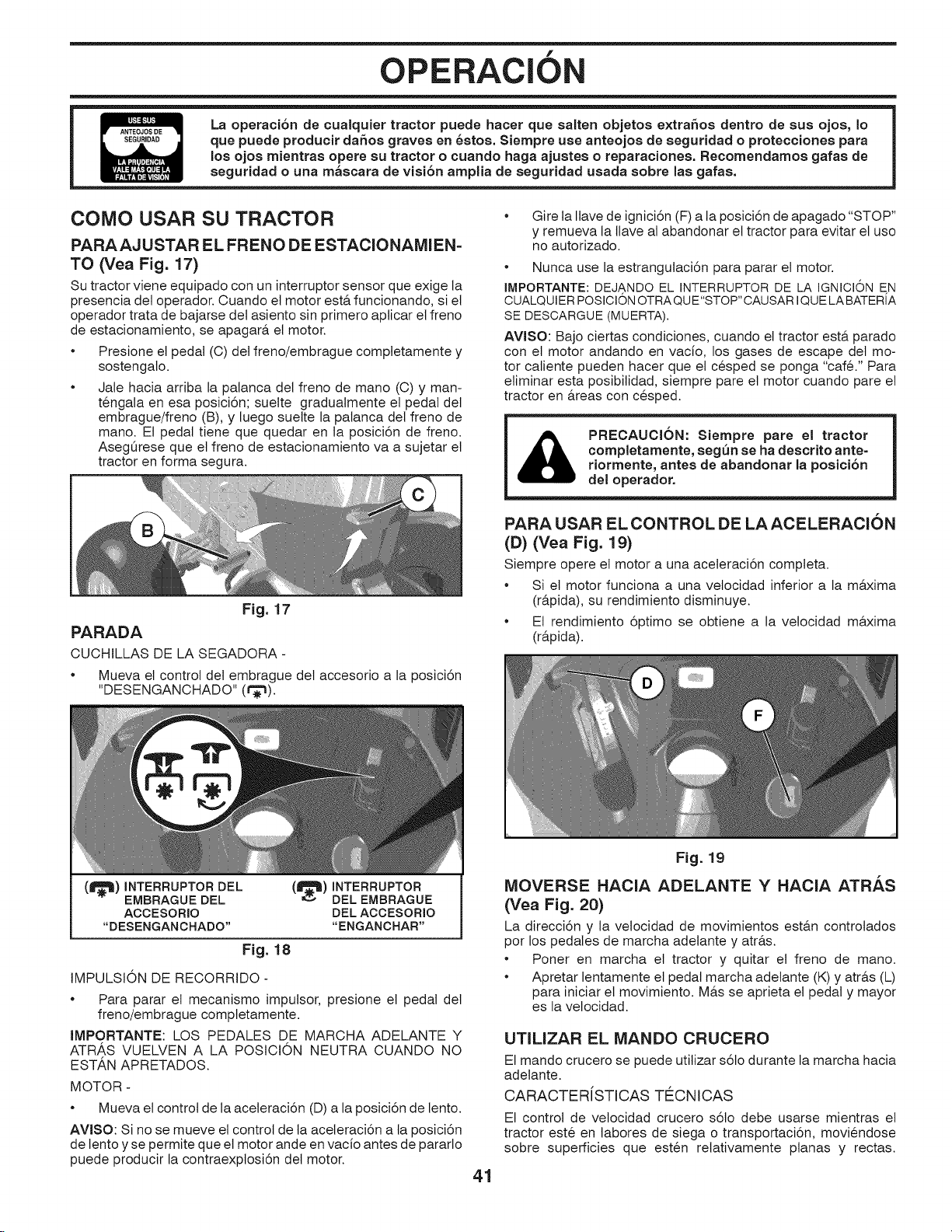
f
OPERAClON
La operaci6n de cualquier tractor puede hacer que salten objetos extrahos dentro de sus ojos, Io
que puede producir dahos graves en 6stos. Siempre use anteojos de seguridad o protecciones para
los ojos mientras opere su tractor o cuando haga ajustes o reparaciones. Recomendamos gafas de
seguridad o una m_scara de visi6n amplia de seguridad usada sobre las gafas.
COMO USAR SU TRACTOR
PARAAJ USTAR EL FRENO DE ESTACIONAMIEN=
TO (Vea Fig. 17)
Su tractor viene equipado con un interruptor sensor que exige la
presencia det operador. Cuando el motor est& funcionando, si et
operador trata de bajarse del asiento sin primero apticar et freno
de estacionamiento, se apagar& et motor.
• Presione el pedal (C) det freno/embrague comptetamente y
sostengalo.
• Jale hacia arriba la palanca del freno de mano (C) y man-
tengala en esa posici6n; suelte gradualmente el pedal det
embrague/freno (B), y luego suelte la palanca del freno de
mano. El pedal tiene que quedar en ta posici6n de freno.
AsegOrese que et freno de estacionamiento va a sujetar et
tractor en forma segura.
Fig. 17
PARADA
CUCHILLAS DE LA SEGADORA -
• Mueva el control det embrague det accesorio a la posici6n
"DESENGANCHADO" (t_).
* Gire ta Ilave de ignici6n (F) a la posici6n de apagado "STOP"
y remueva la Ilave al abandonar et tractor para evitar et uso
no autorizado.
Nunca use la estrangutaci6n para parar et motor.
IMPORTANTE: DEJANDO EL INTERRUPTOR DE LA IGNICKDNE,N
CUALQUIERPOSICK_NOTRAQUE"STOP"CAUSARIQUE LABATERIA
SE DESCARGUE (MUERTA).
AVlSO: Bajo ciertas condiciones, cuando el tractor est& parado
con et motor andando en vacfo, los gases de escape det mo-
tor caliente pueden hacer que et cesped se ponga "care." Para
etiminar esta posibilidad, siempre pare et motor cuando pare et
tractor en &teas con cesped.
completamente, seg_n se ha descrito ante=
PRECAUClON: Siempre pare el tractor
riormente, antes de abandonar la posici6n
del operador,
PARA USAR EL CONTROL DE LA ACELERACION
(D) (Vea Fig. 1g)
Siempre opere et motor a una aceteraci6n completa.
Si el motor funciona a una vetocidad inferior a la m&xima
(r&pida), su rendimiento disminuye.
Et rendimiento 6ptimo se obtiene a la velocidad m&xima
(r&pida).
(_)INTERRUPTORDEL
EMBRAGUE DEL
ACCESORIO
"DESENGANCHADO"
(_)INTERRUPTOR
DELEMBRAGUE
DELACCESORIO
"ENGANCHAR"
Fig. 18
IMPULSION DE RECORRIDO -
• Para parar el mecanismo imputsor, presione et pedal det
freno/embrague comptetamente.
IMPORTANTE: LOS PEDALES DE MARCHA ADELANTE Y
ATRAS VUELVEN A LA POSICION NEUTRA CUANDO NO
ESTAN APRETADOS.
MOTOR -
Mueva et control de la aceteraci6n (D) a laposici6n de lento.
AVISO: Si nose mueve et control de taaceteraci6n a la posici6n
de lento y se permite que etmotor ande en vacio antes de pararlo
puede producir la contraexptosi6n del motor.
Fig. 19
IVlOVERSE HACIA ADELANTE Y HACIA ATRAS
(Vea Fig. 20)
La direcci6n y la velocidad de movimientos est&n controlados
pot los pedales de marcha adelante y atr&s.
* Poner en marcha el tractor y quitar et freno de mano.
* Apretar lentamente el pedal marcha adetante (K) y atr&s (L)
para iniciar et movimiento. M&s se aprieta el pedal y mayor
es la vetocidad.
UTILiZAR EL IVIANDO CRUCERO
El mando crucero se puede utilizar s6to durante la marcha hacia
adetante.
OARAOTER[STIOAS TE_ONIOAS
El control de velocidad crucero s61o debe usarse mientras el
tractor este en tabores de siega o transportaci6n, moviendose
sobre superficies que esten retativamente ptanas y rectas.
41

OPERAClON
Fig. 20
Otras condiciones de trabajo, como la poda, que requiere ve-
Iocidades bajas, podrian desengranar el control de vetocidad
crucero. No emplee et control de velocidad crucero mientras
et tractor se desptaza pot elevaciones, terrenos escarpa-
dos o mientras el tractor este en labores de poda o virando.
• Con el pedal (K) de marcha adetante apretado a la veloci-
dad deseada, mover la palanca de mando de crucero hacia
adelante hasta la posici6n "SET" y mantenerla mientras se
levanta etpie det pedal, luego soltar la palanca (J) de mando
de crucero.
• Para desconectar et control de crucero, tire la patanca hacia
atr&s a ta posici6n "OFF", o empuje comptetamente et pedal
del freno.
PARA AJUSTAR LA ALTURA DE CORTE DE LA
SEGADORA (VEA FIG. 21)
La posici6n de la patanca elevadora (A) determina a que attura
se cortar& el cesped.
f
PARA AJUSTAR LAS RUEDAS CALIBRADORAS
(Vea Fig. 22)
Las ruedas calibradoras est&n bien ajustadas cuando se en-
cuentran un poco a distancia det terreno al mismo tiempo que ta
segadora este a la altura de corte deseada. Entonces las ruedas
catibradoras mantienen el conjunto segador en posici6n para
prevenir et corte raspeo en casi todos los terrenos.
AVlSO: Ajuste las ruedas calibradoras con et tractor en una
superficie nivetada plana.
1. Ajuste la segadora a laaltura de corte deseada con la manitla
de ajuste de attura (Vea "PARA AJUSTAR LA ALTURA DE
CORTE DE LA SEGADORA:' en tasecci6n de Operaci6n de
este manual).
2. Con la segadora a la altura deseada para la posici6n de corte,
se tienen que montar las ruedas calibradoras de modo que
queden un poco sobre elsuelo. Instate las ruedas calibradoras
en etagujeroadecuadocomoindicados.Apriete con seguridad.
3. Repita el procedimiento para et lado opuesto instalando la
rueda calibradora en et mismo agujero de ajuste.
Fig. 22
PARA OPERAR LA SEGADORA
Su tractor viene equipada con un interruptor sensor que exige
la presencia del operador. Si et motor est& funcionando y el em-
brague del accesorio est& enganchado y et operador trata de
bajarse del asiento, se apagar& et motor. Tiene que mantenerse
sentado completa y centralmente en el asiento para impedir que
el motor vacite o se apague cuando se opere su equipo en terreno
disparejo, &spero o en cerros.
• Elija a que altura cortar& et cesped (Vea" PARA AJUS-TAR
LA ALTURA DE CORTE DE LA SEGADORA".)
• Haga arrancar las cuchillas de la segadora enganchando et
control det embrague det accesorio.
Fig. 21
• Coloque la patanca elevadora en la ranura de la attura de-
seada.
La gama de la altura de corte es de aproximadamente 1 a 4
pulgadas. Las alturas se miden desde el suelo a la punta de la
cuchilla cuando el motor no est& funcionando. Estas alturas son
aproximadas y pueden variar dependiendo de las condiciones
del suelo, de la attura del cesped y del tipo del cesped que se
est& segando.
• El cesped promedio debe cortarse aproximadamente a
2-1/2 pulgadas durante la temporada fria y sobre 3 pulgadas
durante los meses calurosos. Para obtener un cesped m&s
saludable y de mejor apariencia, siegue amenudo y despues
de un crecimiento moderado.
Para obtener el mejor rendimiento de corte, el cesped que
tiene m&s de 6 pulgadas de altura debe segarse dos veces.
Haga el primer corte relativamente alto; el segundo a taattura
deseada.
PARA PARAR LAS CUCHILLAS DE LA SEGADORA
• Desenganche et control det embrague det accesorio.
el recogedor de c_sped completo en laa sega-
_ PRECAUCI6N: No opere la segadora sin, ya sea,
doras asi equipadas o con la protecci6n contra
la descarga an su lugar (Vea Fig. 23),
m __
Fig. 23
42
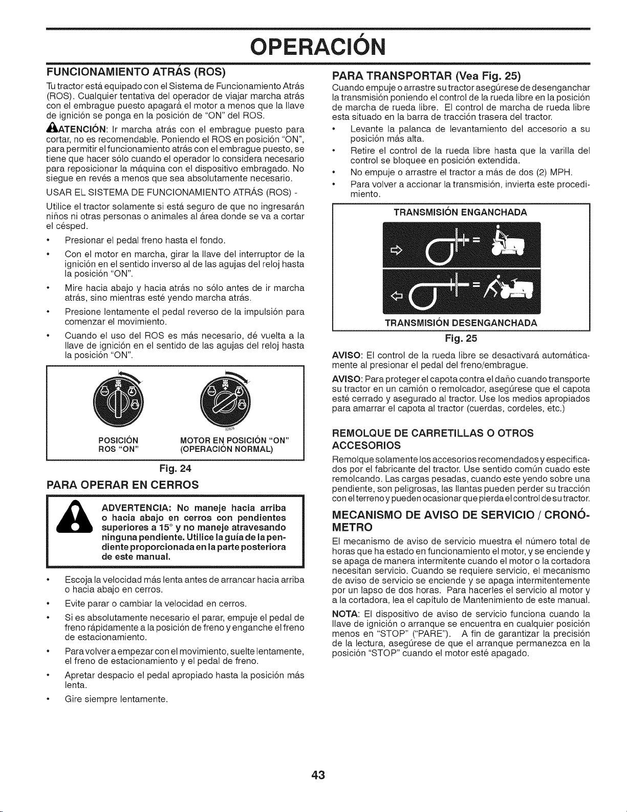
OPERAClON
"7
FUNCIONAMIENTO ATRAS (ROS)
Tutractor est,, equipado con et Sistema de Funcionamiento Atr&s
(ROS). Cualquier tentativa del operador de viajar marcha atr&s
con el embrague puesto apagar& et motor a menos que la Ilave
de ignici6n se ponga en la posici6n de "ON" det ROS.
,,I_,ATENCI6N: Ir marcha atrb,s con el embrague puesto para
cortar, no es recomendable. Poniendo el ROSen posici6n "ON",
para permitir et funcionamiento atr&s con et embrague puesto, se
tiene que hacer s6to cuando el operador Io considera necesario
para reposicionar la m&quina con et dispositivo embragado. No
siegue en reves a menos que sea absolutamente necesario.
USAR EL SISTEMA DE FUNCIONAMIENTO ATRAS (ROS) -
Utilice et tractor sotamente si est& seguro de que no ingresar&n
niflos ni otras personas o animales al &rea donde se va a cortar
et cesped.
Presionar et pedal freno hasta et fondo.
Con et motor en marcha, girar la llave del interruptor de ta
ignici6n en elsentido inverso al de las agujas det retoj hasta
la posici6n "ON".
Mire hacia abajo y hacia atr&s no s61o antes de ir marcha
atr&s, sino mientras este yendo marcha atr&s.
Presione lentamente el pedal reverso de la imputsi6n para
comenzar el movimiento.
Cuando el uso det ROSes m&s necesario, de vuetta a la
Ilave de ignici6n en et sentido de las agujas det retoj hasta
la posici6n "ON".
f
PARA TRANSPORTAR (Yea Fig. 25)
Cuando empuje o arrastre su tractor aseg_rese de desenganchar
la transmisi6n poniendo et control de la rueda libre en la posici6n
de marcha de rueda fibre. El control de marcha de rueda fibre
esta situado en la barra de tracci6n trasera del tractor.
• Levante la patanca de levantamiento det accesorio a su
posici6n m&s alta.
• Retire et control de la rueda fibre hasta que la varilla det
control se bloquee en posici6n extendida.
• No empuje o arrastre et tractor a m&s de dos (2) MPH.
• Para volver a accionar la transmisi6n, invierta este procedi-
miento.
TRANSMISION ENGANCHADA
TRANSMISION DESENGANCHADA
Fig. 25
AVlSO: El control de la rueda libre se desactivar& autom&tica-
mente al presionar el pedal del freno/embrague.
AVISO: Para proteger el capota contra et daflo cuando transporte
su tractor en un cami6n o remotcador, asegOrese que el capota
este cerrado y asegurado al tractor. Use los medios apropiados
para amarrar et capota al tractor (cuerdas, cordetes, etc.)
POSICION
ROS "ON"
MOTOR EN POSICION "ON"
(OPERACION NORMAL)
Fig. 24
PARA OPERAR EN CERROS
ADVERTENCIA: No maneje hacia arriba
o hacia abajo en cerros con pendientes
superiores a 15° y no maneje atravesando
ninguna pendiente. Utilice la guia de la pen=
diente proporcionada en la parte posteriora
de este manual.
Escoja la vetocidad m&s tenta antes de arrancar hacia arriba
o hacia abajo en cerros.
Evite parar o cambiar la vetocidad en cerros.
Si es absotutamente necesario et parar, empuje el pedal de
freno r&pidamente a laposici6n de freno y enganche et freno
de estacionamiento.
Paravolver a empezar con etmovimiento, suette lentamente,
el freno de estacionamiento y et pedal de freno.
Apretar despacio et pedal apropiado hasta la posici6n m&s
lenta.
Gire siempre lentamente.
REMOLQUE DE CARRETILLAS O OTROS
ACCESORIOS
Remolque solamente los accesorios recomendados y especifica-
dos por et fabricante del tractor. Use sentido com0n cuado este
remotcando. Las cargas pesadas, cuando este yendo sobre una
pendiente, son peligrosas, las tlantas pueden perder su tracci6n
con elterreno y pueden ocasionar que pierda etcontrol de sutractor.
MECANISMO DE AVISO DE SERVlClO / CRONO=
METRO
El mecanismo de aviso de servicio muestra et nOmero total de
horas que ha estado en funcionamiento el motor, y se enciende y
se apaga de manera intermitente cuando et motor o la cortadora
necesitan servicio. Cuando se requiere servicio, el mecanismo
de aviso de servicio se enciende y se apaga intermitentemente
por un tapso de dos horas. Para hacerles et servicio at motor y
a la cortadora, lea el capituto de Mantenimiento de este manual.
NOT.&: Et dispositivo de aviso de servicio funciona cuando la
Ilave de ignici6n o arranque se encuentra en cualquier posici6n
menos en "STOP" ("PARE"). A fin de garantizar la precisi6n
de la lectura, asegQrese de que el arranque permanezca en la
posici6n "STOP" cuando el motor este apagado.
43

OPERACION
f
ANTES DE HACER ARRANCAR EL MOTOR
REVISE EL NIVEL DE ACEITE DEL MOTOR
El motor de su tractor se envia de f&brica ya Ileno con aceite de
peso para verano.
Revise et aceite det motor con et tractor en terreno nivelado.
Remueva la tapa/varilla indicadora de nivet de relleno del
aceite y limpielas, vuelva a insertar la varitla indicadora de
nivet y atornille la tapa hasta que quede apretada, espere
por unos cuantos segundos, remuevala y tea et nivel det
aceite. Si es necesario, agregue aceite hasta que se haya
alcanzado la marca Ileno (FULL) en la varilla indicadora de
nivet. No Io Ilene demasiado.
Para la operaci6n en clima frio, debe cambiar el aceite para
poder arrancar m&s f&cilmente. (Vea "Tabta de Viscosidad
Del Aceite" en tasecci6n de Mantenimento de este manual.)
Para cambiar et aceite det motor, vea la secci6n de Manteni-
mento en este manual.
AGREGUE GASOLINA
Llene et tanque de combustible hasta la parte inferior det
cuetlo de relteno. No Io tlene de m&s. Use gasolina normal
nueva y limpia con un minimo de 87 octanos. No mezcte
aceite con gasolina. Compre combustible en cantidades
que se puedan usar en 30 dias para asegurar la frescura
det combustible.
&
IMPORTANTE: CUANDO SE OPERE EN TEMPERATURAS
POR DEBAJO DE 32°F (0°C) USE GASOLINA DE INVIERNO
LIMPIA Y NUEVA PARA AUEDAR A ASEGURAR UN BUEN
ARRANQUE EN CLIMA FR[O.
PRECAUCI6N: Los combustibles mezclados con al-
cohol (llamados gasohol o que usan etanol o metano0
pueden atraer la humedad, Io que provoca Is separaci6n
y formaci6n de 6cidos durante el almacenamiento. El
gas 6cido puede daflar el sistema de combustible de
un motor mientras se encuentra en almacenamiento.
Para evitar problemas con el motor, el sistema de
combustible se debe vaciar antes del almacenamiento
durante 30 dias o m6s. Drene el tanque de gasolina,
arranque el motor y h6galo funcionar hasta que las
tuberias de combustible y del carburador est6n vacias
Use combustible nuevo en la temporada siguiente.
Consulte las Instrucciones de AImacenamiento para
obtener informaci6n adicional. Nunca use productos
limpiadores para motor o carburador en el tanque de
combustible porque puede provocar daSos irreparables.
Elestabilizador de combustible es una alternativa acept=
able para minimizar la formaci6n de dep6sitos de goma
de combustible durante el almacenamiento. Agregue
estabilizador a la gasolina en el tanque de combustible
o recipiente de almacenamiento. Siga siempre la pro=
porci6n de mezcla que se encuentra en el recipiente del
estabilizador. Deje funcionar el motor al menos durante
10 minutos despu6s de agregar el estabilizador para
permitir que el estabilizador Ilegue al carburador. No
vacie el tanque de gasolina y el carburador si utiliza
estabilizador de combustible.
PARA HACER ARRANCAR EL MOTOR (Vea Fig. 16)
AI hacer arrancar et motor por la primera vez o si se ha acabado
et combustible det motor, se necesitar& tiempo para et arranque
extra para mover et combustible desde el estanque hasta etmotor.
AsegQrese que et control de rueda libre este en la posici6n
enganchada.
Sientase en el sitl6n en ta posici6n de operaci6n, suelte et
pedal det freno y ponga et freno de estacionamiento.
Mueva el embrague det accesorio a la posici6n desen-
ganchado.
Mueva la palanca de control de la aceteraci6n a la posici6n
de estrangutaci6n.
AVISO: Antes de arrancar, lea las instrucciones siguientes para
et arranque en ctima frio y temptado.
Inserte la Ilave en ta ignici6n y gire la Ilave en et sentido que
giran las manillas det retoj a la posici6n de arranque start, y
suelte la tlave tan pronto como arranque el motor. No haga
funcionar et arrancador continuamente por m&s de quince
seg.undos pot minuto. Si el motor no arranca despues de
vanos intentarlos, mueva el control de la aceteraci6n a la
posici6n de r&pido, espere unos cuantos minutos y trate de
nuevo. Si el motor sigue sin funcionar, mueva el control de
la aceteraci6n a la posici6n de estrangutaci6n y intente de
nuevo.
ARRANQUE CON TIEMPO TEMPLADO (50° F/10°C y m&s)
Cuando arranque el motor, mueva et control de la acetera-
ci6n a la posici6n de r&pido.
Los accesorios y et embrague ahora pueden ser utilizados.
Si el motor no acepta esta carga, vuetva a arrancar
et motor para permitirle que se caliente por un minuto
utilizando el estrangutador como describido arriba.
ARRANQUE OON TIEMPO FR[O (50 ° F/10°O y menos)
AI hacer arrancar et motor, mantenga el control de la
aceleraci6n a la posici6n de estrangulaci6n hasta que et
motor se caliente y empieze funcionar mal. Una vez que
empieze a funcionar mal, mueva inmediatamente el control
de la aceteraci6n a la posici6n r&pida. Et calentamiento del
motor puede tomar a partir de varios segundos a varios
minutos (cuanto m&s fria es la temperatura, m&s largo es el
calentamiento).
CALENTAMIENTO PARA LA TRANSMISION AUTOMATICA
Antes de conducir la unidad en un tiempo frio, la transmisi6n debe
ser calentada como las instrucciones siguientes:
AsegQrese que ettractor este situado en una superficie
nivelada.
Alivie et freno de estacionamiento y deje que et freno
vuelva a la posici6n de operaci6n.
Permita que tatransmisi6n se caliente durante un minuto.
Esto puede ser echo durante ettiempo de calentamiento
del motor.
Los accesorios pueden ser utilizados durante el periodo del
recalentamiento det motor despues que la transmisi6n halla
sido calentada.
44

OPERAClON
CONSEJOS PARA SEGAR
• NO use cadenas de llanta cuando la carcasa de la cortadora
de cesped este colocada en ettractor.
La segadora debe estar nivelada en forma adecuada para
obtener el mejor rendimiento al segar. Vea "PARA NIVELAR
LA CAJA DE LA SEGADORA:' en la secci6n de Servicio y
Ajustes de este manual.
El lado izquierdo de la segadora se debe usar para recorte.
Maneje de modo que los recortes se descarguen en et &rea
que ya ha sido cortada. Mantenga el &rea de corte a la
derecha del tractor. Esto producir& una distribuci6n m&s
pareja de los recortes y un corte m&s uniforme.
AI segar las &rea grandes, empiece girando a la derecha
de modo que los recortes se descarguen, alej&ndose de los
arbustos, cercos, entradas de autom6viles, etc. Despues de
una o dos vuettas, siegue en ta direcci6n opuesta, haciendo
virajes a la izquierda, hasta que termine (Vea Fig 26).
Si et cesped est& demasiado alto, se debe segar dos veces
}.
f
lrI
C
J
Fig, 26
para reducir la carga y los posibtes petigros de incendio
debido a los recortes secos. Haga et primer corte relativa-
mente alto; et segundo a la altura deseada.
No siegue el cesped cuando esta.mojado. Et cesped mojado
taponar& la segadora y dejar& montones indeseabtes. Per-
mita que se seque et cesped antes de segarto.
Siempre opere etmotor con una aceleraci6n compteta cuando
siegue para asegurarse de conseguir un mejor rendimien-
to y una descarga apropiada de los materiales. Regule la
vetocidad de recorrido seteccionando un cambio 1osuficien-
temente bajo para obtener un rendimiento de corte de parte
de su segadora y tambien ta calidad det corte deseada.
Cuando opere con accesorios, seteccione una vetocidad de
recorrido que se acomode al terreno y le permita obtener et
mejor rendimiento det accesorio que se est& usando.
45

MANTENIMIENTO
PROGRAMA DE MANTENIMIENTO
Revisar la operaci6n del freno
Revisar la presi6n de las ttantas
Verificar la sistemas presencia det operador y sistemas "ROS '_
t Revisar si hay sujetadores sueltos
a Afilar/cambiar tas cuchillas de la segadora
Tabta de tubricaci6n
m Revisar et nivet de bateria
0 Limpiar ta bateria y los tereminales
R Limpie los residuos de la placa de direcci6n.
Compruebe la nivetaci6n del cortacespedes
Inspeccione las correas trapezoidales
Revisar el nivel del aceite del motor
Cambiar el aceite del motor (Modelos con filtro de aceite)
Cambiar el aceite del motor (Modelos sin filtro de aceite)
Limpiar el filtro de aire
t Limpiar la rejilla de aire
O Inspeccionar el silenciador/amortiguador de chispas
a Cambiar el filtro de aceite (si equipado)
Limpiar las aletas de enfriamiento
Cambiar ta bujia
Cambiar el cartucho de papel del filtro de aire
Cambiar el filtro de combustible
1- Cambiar mAs a menudo cuando se opere bajo carga pesada o en ambientes con altas temperaturas
2- Dar servicio mAs a menudo cuando se opere en condiciones sucias o polvorosas
ANTES DE CADA
CADAUSO 8HORAS
i/ t/
t/ i/
t/
i/ i/
3=Cambiar las cuchillas mas a menudo cuando se siegue en suelo arenoso
4- No requeddo s} equipado con una bateria libre de mantenimiento
CADA CADA CADA CADA
25 HORAS 50 HORAS 100 HORAS TEMPORADA
ALMACENAMIENTO
t/ t/
t/ i/
i/ i/
i/
_1,2
_1,2
i/
t/
i/
5=Yea "LIMPJEZA" en la secci6n de
Mantenirnento de este manual
i/
RECOMENDACIONES GENERALES
La garantia de este tractor no cubre los articutos que han estado
sujetos al abuso o a la negligencia del operador. Para recibir todo
etvalor de la garantia, eloperador tiene que mantener lasegadora
segQn las instrucciones descritas en este manual.
Hay algunos ajustes que se tienen que hacer en forma peri6dica
para poder mantener su tractor adecuadamente.
AI menos una vez cada estaci6n comprobar si es necesario
efectuar los adjustes descritos en las secciones de Servicio y
Ajustes de este manual.
Una vez al aflo, cambie la bujia, limpie o cambie el filtro de
aire y revise si las cuchitlas y tas correas est&n desgastadas.
Una bujia nueva y unfiltro de aire limpio aseguran una mezcta
de aire-combustible adecuada y le ayudan a que su motor
funcione mejor y que dure m&s.
ANTES DE CADA USO
Revise et nivet del aceite det motor.
Revise la operaci6n de los frenos.
Revise la presi6n de las Itantas.
Verifique que et sistema de presencia det operado y ROS
funcionen adecuatamente.
Revise si hay sujetadores suettos.
TABLA DE LUBRICACK)N
(_ ACCESORIO
DE GRASA DEI
ARBOL
@
DE GRASA DEL
RODAMIENTO
DE LA RUEDA
DELANTERA
.1_ACCESORIO
DE GRASA DEL
ARBOL
ACOESORIO
DE GRASA DEL
RODAMIENTO
DE LA RUEDA
DELANTERA
@
DEL
ENGRANAJE
DE SECTOR
DE
DIRECCI6N
02501
ACCESORJO
DE GRASA
DELMANDRIL
(_ Grasa de proposito general
(_ Refi@ase a la secci6n del "MOTOR" en Mantenimiento
IMPORTANTE: NO ACEITE O ENGRASE LOS PUNTOS PIVOTES,
LOS QUE TIENEN RODAMIENTOS DE NILON ESPECIALES. LOS
LUBRICANTES VlSCOSOS ATRAER#,N POLVO Y MUGRE, LO QUE
ACORTARA LA DURACJON DE LOS RODAMIENTS. SI CREE QUE
LUBRICARSE, USE SOLAMENTE UN LUBRICANTE TIPO GRAFITO
DE POLVO SECO EN FORMA MODERADA.
46
MOTOR

MANTENIMIENTO
TRACTOR
Siempre observe las regtas de seguridad cuando de manteni-
miento.
OPERACION DEL FRENO
Si et tractor necesita m&s de cinco (5) pies para detenerse
a la m&xima velocidad al cambio m&s alto en una superficie
nivetada, de hormig6n o pavimentada, hay que hacerle
et servicio al freno. Vea "CONTROLAR Y AJUSTAR EL
FRENO" en et capituto de Servicio y ajustes de este manual.
LLANTAS
• Mantenga todos los neum&ticos con la presi6n de aire
adecuada (Vea la PSI que se indica en estos).
• Mantenga las Ilantas sin gasolina, aceite o substancias
quimicas para control de insectos que pueden daflar la goma.
• Evite los tocones, las piedras, las grietas profundas, los
objetos afilados y otros petigros que pueden daflar alas
Ilantas.
AVlSO: Para arreglar las Ilantas perforadas y pera prevenir
que tenga Ilantas pinchadas a causa de pequeflas fugas, puede
comprar et setlo para Ilantas de su comerciante de partes de
repuesto m&s cercano. Etsetlo previene que las tlantas se sequen
y tambien la corrosi6n.
SISTEMA PRESENCIA OPERADOR Y SISTEMA FUN=
CIONAMIENTO ATRh.S (ROS) (Vea Fig. 27)
Asegurarse de que el sistema de presencia del operador, el
sistema de trabajo y el sistema funcionamiento atr&s funcionen
bien. Si tu tractor no funci6n como descrito, reparar et probtema
inmediatamente.
El motor no arrancar& si et pedal de embrague/freno est&
comptetamente presionado y el mando det embrague det
accesorio est& desconectado.
V#RIFIEZ SlSTEMA PRESENCIA OPERADOR
Cuando et motor est& en marcha, cualquier tentativa det
operador de abandonar el asiento sin haber puesto et freno
de estacionamiento primero, apagar& et motor.
Cuando et motor est& en marcha y el embrague del
accesorio est& conectado, cualquier tentativa det operador
de abandonar el asiento, apagar& el motor.
El embrague del accesorio no tendria que funcionar nunca
si et operador no est& en su asiento.
V#RIFI#Z SISTEMA FUNCIONAMIENTO ATR,AS (ROS)
Cuando et motor est& en marcha con el interruptor de llave
en posici6n de motor "ON" y el embrague del accesorio
conectado, cualquier tentativa det operador de viajar marcha
atr&s, apagar& et motor.
Cuando etmotor est& en marcha con elinterruptor de tlave del
sistema de funcionamiento atr&s (ROS) en la posici6n "ON"
y el embrague del accesorio conectado, cualquier tentativa
det operador de viajar marcha atr&s, NO apagar& et motor.
POSICION
ROS "ON"
MOTOR EN POSlCI6N "ON"
(OPERACION NORMAL)
Fig. 27
CUIDADO DE LA CUCHILLA
Para obtener resuttados 6ptimos, las cuchillas de la cortadora
deben estar afiladas. Reemptace tascuchillas que esten gastadas,
dobtadas o dafladas.
PRECAUCI6N: Usar solamente la hojas de
repuesto aprobada pot el fabricante de su
cortac6sped. Usar una hoja no aprobada
pot el fabricante de su cortac6sped as
peligroso, puede da_ar su cortac6sped y
anular su garantia.
REMOCION DE LA CUCHILLA (Vea Fig. 28)
• Levante la segadora a su posici6n m&s alta para permitir et
acceso alas cuchitlas.
AVlSO: Proteja sus manos con guantes y/o envuetva la cuchilla
con una teta gruesa.
Remueva etperno de la cuchitla dandole vuettas en etsentido
inverso al de las agujas det retoj.
Instale la nueva cuchitla o cuchilla afilada con et estampado
"THIS SIDE UP" en ladireccion de lasegadora y det conjunto
det mandril.
IMPORTANTE: PARA ASEGURAR LA INSTALACION APRO-
PIADA, POSICIONE ELAGUJERO CENTRAL DE LA CUCHILLA
CON LA ESTRELLA DEL CON JUNTO DEL MANDRIL.
Instale y apriete etperno de lacuchilla firmemente (62-75 Nm).
IMPORTANTE: EL PERNO DE LA CUCHILLA ES TRATADO
A CALO.
y\ CONJUNTO DEL
_,_ "_ MANDRIL
AGUJERO
Fig. 28
ESTRELLA
BATERiA
Su tractor cuenta con un sistema de carga de la baterfa que es
suficiente para el uso normal. Sin embargo, si se carga la bater[a,
peri6dicamente, con un cargador de autom6viles se prolongar&
su duraci6n.
* Mantenga la bater[a y los terminales limpios.
* Mantenga los pernos de la bater[a apretados.
* Mantenga los agujeros de ventilaci6n pequeflos abiertos.
* Vuetva a cargar a 6-10 amperes por 1 hora.
AVlSO: La bateria det equipo original de su tractor no becesita
servicio. No intente abrir o remover las tapas o cubiertas. No
esnecesario afladir o verificar el nivet det electr6tito.
PARA LIMPIAR LA BATER[A Y LOS TERMINALES -
La corrosi6n y ta mugre de la bater[a y de los terminales pueden
producir "escapes" de potencia en la bater[a.
* Levantan el capota.
* Desconecte el cable de la bater[a NEGRO primero y luego
et cable de la bater[a ROJO y remueva la bater[a det tractor.
* Enjuague la bater[a con agua corriente y sequela.
* Limpie los terminates y los extremos det cable de la bater[a
con un cepillo de alambre hasta que queden brillantes.
* Cubra los terminales con grasa o parafina.
* Reinstale la bater[a (Vea "REEMPLAZAR LA BATERIA:' en
la secci6n de Servicio y Ajustes de este manual).
47

MANTENIMIENTO
CORREAS"V"
Revise tas correas "V" paraverificar si existe deterioro y desgaste
despues de 100 horas de operaci6n y c&mbielas si es necesario.
Las correas no son ajustabtes. Cambie las correas si empiezan
a destizarse debido al desgaste.
ENFRIAMIENTO DEL TRANSEJE
Et transeje ha sido seltado en la f&brica y el mantenimiento del
fluido no es necesario para la vida del transeje. En et caso de
que el transeje se fittrase o necesitase servicio, haga et favor de
ponerse en contacto con un otro centro de servicio cualificado.
MOTOR
LUBRICACION
Use sotamente aceite dedetergente dealta catidad ctasificado con la
clasificaci6n SG-SLde servicio API. Seteccione lacatidad de viscos-
idaddet aceite SAE seg_n su temperatura de operaci6n esperada.
CALIDADES DE VISCOSIDAD DE SAE
F -20 0 30 32 40 60 80 100
o -_0 -2; -1; ; 10 _0 _0 4;
GAMA DE TEMPERATURA ANTICIPADA ANTES DEL PROXIMO CAMBIO DE ACEITE
AVlSO: A pesar de que los aceites de muttiviscosidad (5W30,
10W30, etc.) mejoran et arranque en clima frio, estos aceites de
muttiviscosidad van a aumentar el consumo de aceite cuando
se usan en temperaturas sobre 32° F (0° C). Revise et nivet det
aceite det motor m&s a menudo, para evitar un posibte daflo en
et motor, debido a que no tiene suficiente aceite.
Cambie el aceite despues de 25 horas de operaci6n o por Iome-
nos una vez at aflo si el tractor se utitiza menos 25 horas et aflo.
Revise el nivel det aceite det c&rter antes de arrancar el motor
y despues de cada ocho (8) horas de uso continuado. Apriete
la tapa del relteno/varilla indicadora de nivel det aceite en forma
segura cada vez que revise et nivel det aceite.
PARA CAMBIAR EL ACEITE DEL MOTOR
(Vea Fig. 29)
Determine la gama de la temperatura esperada antes de cam-
biar et aceite. Todo etaceite debe cumptir con la clasificaci6n de
servicio API SG-SL.
AsegOrese que el tractor este en una superficie nivetada.
Et aceite se drenar& m&s f&cilmente cuando este catiente.
Recoja et aceite en un envase adecuado.
Remueva la tapa/varilla indicadora de nivet para relteno del
aceite. Tenga cuidado de no permitir que la mugre entre en
et motor cuando cambie et aceite.
Quite et casquitlo de la guarnici6n inferior de la v&tvula de
desagQe e instale et tubo de desagQe sobre la guarnici6n.
V/_LVULA DE DESAGUE DEL ACEITE
POSICION
CERRADA Y
BLOQUEADA
Abra la v&tvuta de desagQe empujando hacia dentro y dando
vuetta a la izquierda.
Para abrirse, tire hacia fuera la v&tvuta de desagOe.
Despues de que el aceite haya drenado total-mente, cerrar
y btoquee la v&lvula de desagQe empujando hacia dentro y
dando vuetta en sentido de las agujas de un reloj hasta que
la ctavija est& en la posici6n btoqueada segOn Io mostrado.
Remueva el tubo de desagOe y substituya et casquitlo sobre
la guarnici6n inferior de la v&tvula de desagQe.
Vuetva a Ilenar et motor con aceite a traves det tubo de la
varilla indicadora de nivel para retteno del aceite. Vacfelo
lentamente. No lotlene demasiado. Para la capacidad aproxi-
mada vea las "Especificaciones det Producto" secci6n de
este manual.
Use un medidor en ta tapa/varilla indicadora del nivel para
relleno det aceite para revisar et nivel. Mantenga et aceite
en la linea de lleno (FULL) en ta varilla indicadora de nivel.
Apriete la tapa en ettubo en forma segura cuando termine.
FILTRO DE ACEITE DEL MOTOR
Cambie el filtro de aceite del motor cada temporada o vez por
medio que cambie etaceite, si et tractor se usa m&s de 100 horas
en un aflo.
FILTRO DEL AIRE
Su motor puede sufrir averias y funcionar de manera incorrecta
con un filtro del aire sucio. Dele servicio al filtro de aire m&s a
menudo si se usa en condiciones polvorosas. Vea la manual de
la motor.
LIMPIEZA DE LA PANTALLA DE AIRE
La pantalla de aire est& sobre et soptador de la toma de aire
que se ubica en la parte superior del motor. La pantalla de aire
se debe mantener libre de suciedad y paja para evitar que et
motor se dafle por sobrecalentamiento. Limpie con un cepillo
de alambre o con aire comprimido para retirar la suciedad y las
fibras de goma secas dificites de quitar.
SISTEMA DE ENFRIAMIENTO DE AIRE
Para asegurar un enfriamiento adecuado, asegOrese que la rejilla
det cesped, las aletas de enfriamiento, y otras superficies externas
det motor se mantengan limpias en todo momento.
Cada 100 horas de operaci6n (m&s a menudo bajo condiciones
extremadamente potvorosas o sucias), remueva la caja det
ventilador y otras tapas de enfriamiento. Limpie las aletas de
enfriamiento y las superficies externas, segQn sea necesario.
AsegOrese que se vuetvan a instalar las tapas de enfriamiento.
AVISO: Si se opera la m&quina con una rejilta det cesped blo-
queada, sucia, o con tas aletas de enfriamiento taponadas, y/o
las tapas de enfriamiento removidas se producir& daflo en et
motor debido al calentamiento excesivo.
BUJiA(S)
Cambie tas bujias al comienzo de cada temporada de siega o
despues de cada 100 horas de operaci6n, 1oque suceda primero.
El tipo de bujfa y el ajuste de la abertura aparecen en "ESPECI-
FICACIONES DEL PRODUCTO" secci6n de este manual.
Ul__ _ TUBO DE
CASQI ___ ,_ _._ ,. DESAGUE
Fig. 29 48

MANTENIMIENTO
SILENCIADOR
Inspeccione y cambie et silenciador corroido y et amortiguador
de chispas (si viene equipado) pues pueden crear un petigro de
incendio y/o daflos.
FILTRO DE COMBUSTIBLE EN LINEA (Vea Fig. 30)
Etfiltro de combustible debe cambiarse una vez cada temporada.
Si el filtro de combustible se tapona, obstruyendo el flujo det
combustible hacia el carburador, es necesario cambiarlo.
• Con el motor frio, remueva et filtro y tapone las secciones
de la linea de combustible.
• Ponga el filtro de combustible nuevo en su posici6n en la linea
de combustible con la flecha seflalando hacia et carburador.
• AsegOrese de que no hayan fugas en la tinea det combus-
tible y que las grapas esten colocadas en forma adecuada.
• Inmediatamente limpie toda la gasolina derramada.
ABRAZADERA ABRAZADERA
FILTRO _--_6f
CO MB U_._1BLE ...._......'_._ u_G7
Fig. 30
LIMPIEZA
®
Limpie todo material extraflo det motor, la bateria, et asiento,
et putido, etc.
®
Limpie los desechos de taplaca guia. Los desechos pueden
limitar et movimiento det eje del pedal det freno/embrague,
Io que har& que patine la correa y que se pierda ta tracci6n.
PRECAUCION: Evite todos los puntos de i
enganche y las piezas m6viles.
f PEDAL DEL EMBRAGUE/FRENO
,r,..............._,- LIMPIAR PARTE
,' PLACADE
/ DIRECCION
SISTEMA DE DIRECCION, SALPICADERO,
GUARDA=BARROS Y SEGADORA NO MOSTRADOS
• Mantenga las superficies putidas y las ruedas sin derrames
de gasolina, aceite, etc.
• Proteja las superficies pintadas con cera tipo automotriz.
Excepto pot el puerto de tavado (si est& inctuido), se recomienda
no utitizar una manguera de jardin ni et lavado a presi6n para
limpiar la parte externa de su tractor, a menos que el motor y la
transmisi6n esten cubiertos para protegertos det agua. Si entra
agua en et motor o la transmisi6n se reducir& tavida [3titdel trac-
tor. Utitice aire comprimido o un soplador de hojas para retirar
el cesped, las hojas y la basura de la parte externa det tractor y
de la cortadora de cesped.
SUPERIOR
Fig. 31
i
J
PUERTO DE LAVADO DE LA CUBIERTA
_ea Fig. 32)
La plataforma det tractor est& equipada con un puerto de lavado
como parte del sistema de lavado de la ptataforma. Se debe
utilizar despues de cada uso.
1. Lleve el tractor a un lugar horizontal y despejado de su
cesped, Io bastante cerca de una boca de riego como para
que Ilegue la manguera del jardin.
IMPORTANTE: AsegOrese de que la boca de descarga del tractor
est& orientada LEJOS de su casa, garaje, coches aparcados, etc.
Quite la boca de ensacado o cubierta de mantillo siesta, acoplada.
2. Mueva et control del embrague del accesorio a la posici6n
"DESENGANCHADO", ponga el freno de estacionamiento
y apague et motor.
3. Enrosque et adaptador de la boquilla (empaquetado con et
manual del operador det tractor) en elextremo de tamanguera
det jardin.
4. Eche hacia atr&s la abrazadera de cierre del adaptador de la
boquitla y empuje este en el puerto de lavado de la cubierta
en elextremo izquierdo de ta cubierta de la segadora. Suelte
la abrazadera de cierre para fijar etadaptador en taboquitla.
Fig. 32
IMPORTANTE: Tire de la manguera para asegurarse de que la
conexi6n est& bien fija.
5. Abra la Ilave det agua.
6. Desde la posici6n del operador del tractor, vuetva a arrancar
et motor y ponga la palanca de aceleraci6n en la posici6n
r&pido (",_").
IMPORTANTE: Vuetva a revisar el &rea para asegurar que est&
despejada. AsegOrese de que no haya niflos en et &rea mientras
limpia la plataforma.
7. Mueva et control det embrague del accesorio a la posici6n
"ENGANCHAR". Mantengase en la posici6n del operador con
la cubierta de corte acoptada hasta que lacubierta este limpia.
8. AsegOrese de que etcontrol del embrague del accesorio este
en la posici6n "DESACTWADO". Apague et motor. Apague
et agua.
9. Tire hacia atr&s la abrazadera de cierre del adaptador de la
boquitla para desconectar et adaptador det puerto de lavado
de la cubierta.
10. Lleve eltractor a una zona seca, preferentemente de cemento
opavimentada. Mueva etcontrol del embrague del accesorio
a la posici6n "ENGANCHAR" para quitar el exceso de agua
y ayudar a que se seque antes de guardar el tractor.
roto o no estfi, Ud. y otras personas estarfin ex-
ADVERTENCIA: Si el accesorio de lavado estfi
puestos a qua la hoja les lance aquellos objetos
* Sustituya inmediatamente el accesorio de lavado
. Tape todos los orificios de la segadora con pernos
con los que entre en contacto,
roto o que falta antes de volver a usar la segadora.
y tuercas de seguridad.
49

SERVICIO Y AJUSTES
HACER AJUSTES:
_ DVERTENCIA: PARA EVITAR LESI6NES SERIAS, ANTES DE DAR CUALQUIER SERVICIO O DE
• Presione el pedal de freno completamente y aplique el freno de estacionamiento.
• Asegur_is que el transmisi6n en la posici6n de neutro.
• Ponga el embrague del accesorio en la posici6n desenganchado (DISENGAGED).
• Ponga la Ilave de ignici6n en la posici6n de apagado (STOP) y remu_vala.
• Aseg_rese que las cuchillas y que todas las partes movibles se hayan detenido completamente.
• Desconecte el alambre de la bujia y p6ngalo en donde no pueda entrar en contacto con _sta.
PARA DESMONTAR LA CORTADORA DE ClaSPED
(Vea Fig. 33)
• Suette etembrague poniendolo en taposici6n"DESACTIVADO".
• Baje la palanca etevadora de montaje a la posici6n de m&s
abajo.
• Retire la barra de tensi6n de la correa (K) de la barra de
sujeci6n (L).
C_i6n de la correa _fun=
I oio.a oo oorzayao =to=aI
)acIo,
• Retire la correa de la cortadora de la polea det embrague
etectrico (M).
• Desconecte la pieza de uni6n anterior (E) de la cortadora-
retire et resorte de contenci6n y la arandela.
• Pot uno de los lados de la cortadora, desconecte et brazo
de suspensi6n de la cortadora (A) det chasis y la pieza
de uni6n posterior (C) de la barra posterior de la corta-
dora (D) - retire los resortes de contenci6n y las arandelas.
• Por el otro lado de la cortadora, desconecte et brazo de
suspensi6n y la pieza de uni6n posterior.
_ CUIDADO: Una vez que se desconecten las pie-
zas de uni6n posteriores, la palanca elevadora
funcionar_ a resorte. Sujete con fuerza lapalanca
elevadora al cambiarla de posici6n.
Por et lado derecho de la cortadora, desconecte la barra anti-
balanceo (S) de la barra posterior derecha de la cortadora
(D) - retire el resorte de contenci6n y la arandela, y jale la
cortadora hacia usted hasta que la barra se salga det orificio
de la barra.
Haga girar el volante det tractor todo Io posible a ta izquierda.
Destice la cortadora pot debajo det lado derecho det tractor.
PARA INSTALAR LA SEGADORA
Siga los procedimientos que se describen en "INSTA-LACION
DE LA SEGADORA Y DE LA CORREA DE IMPULSION" en la
secci6n de Montaje de este manual.
PARA REEMPLAZAR LA CORREA DE LA
CUCHILLA DE LA SEGADORA (See Fig. 34)
DESMONTAJE DE LA CORREA DE TRANSMISION DE LA
SEGADORA
• Estacione el tractor en una superficie nivelada. Ponga et freno
de mano.
• Baje la palanca elevadora a la posici6n de m&s abajo.
• Retire la barra de tensi6n de la correa (K) de la barra de
sujeci6n (L).
a resorte. Suj6tela con fuerza y su_ltela
despacio.
• Quite los tornillos (P) de las cubiertas derecha e izquierda y
retirelas (Q).
• Quite toda suciedad y restos de hierbas que pueda haberse
acumutado alrededor de los dispositivos de recolecci6n y de
toda la superficie superior.
• Retire la correa de la potea del embrague electrico (M), las
dos poleas de tos dispositivos de recolecci6n (R) y las poleas
de los pihones (V).
MONTAJE DE LA CORREA DE TRANSMISION DE LA SEGA-
DORA
• Instale la correa pas&ndota alrededor de las poteas (R) y
alrededor de las poteas (V), como se muestra en la figura.
• Pase tacorrea porencima de tapotea del embrague electrico (M).
IMPORTANTE: Verifique que la correa catce bien en todas las
ranuras de las poteas de la cortadora.
• Vuelva a cotocar las cubiertas derecha e izquierda (Q). Ajuste
bien todos los torniltos.
• Coloque la barra de tensi6n de la correa (K) en la barra de
sujeci6n (L).
CUIDADO: La barra de tensi6n funciona
a resorte. Suj6tela con fuerza y p6ngala
despacio.
• Suba la palanca etevadora a la posici6n de m&s arriba.
i
Fig. 33 Fig. 34
50

SERVICIO Y AJUSTES
PARA NIVELAR LA SEGADORA
AsegQrese de que los neum&ticos esten inflados a la PSi
que se indica en estos. Si est&n demasiado inflados o poco
inflados, et cesped no le quedara bien cortado, Io cual podra
Ilevarlo a pensar que la SEGADORA no est& bien regutada.
REGULACION VISUAL DE LADO A LADO (Yea Fig. 35)
* Si todos los neum&ticos est&n correctamente inflados y el
cesped parece haber quedado cortado desparejo, determine
que lado de la cortadora est& cortando m&s al ras.
NOTA: SegOn Io desee, puede subir et lado m&s bajo o bajar et
lado m&s alto de la segadora.
* Aborde el lado de la cortadora que quiera regular.
* Con una Ilave inglesa de 3/4"o de calibre regulable, haga girar
hacia la izquierda la tuerca de ajuste de la pieza de uni6n (A)
para bajar la cortadora, o bien h&gala girar hacia la derecha
para subirla.
Vuelva a verificar tas medidas y ajuste nuevamente, en caso
necesario, hasta que ambos lados queden iguales.
AJUSTE DE DELANTE A ATRAS (Yea Fig. 37 y 38)
IMPORTANTE: El piso debe quedar bien nivetado de lado a lado.
Para que el cesped le quede perfectamente cortado, las
cuchitlas de la cortadora deben ajustarse de tal manera que la
punta anterior quede 1/8" a 1/2" m&s abajo que la punta poste-
rior cuando la cortadora se encuentre en su posici6n m&s alta.
i CUIDADO_ afJladas. Prot_jase
I laa m ual ou i,aa I
&
_con tela gruesa, o bien haga ambas cosas.
Suba la SEGADORA a la posici6n m&s alta.
Ubique cualquiera de las hojas de la cuchitla de tal
manera que la punta quede apuntando directamente
hacia adelante. Mida la distancia (B) que hay entre la
punta anterior y el sueto y entre la punta posterior y et sueto.
Si la punta anterior de la hoja de la cuchitla no est& 1/8" a
Fig. 37
Haga girar la Haga girar la
tuerca nacla la tuerca nacta la
derecha para ,,,,
subir la segadora
Fig. 35
NOTA: Cada vuelta completa de la tuerca de ajuste har& variar
la altura de la cortadora aproximadamente 3/16".
Pruebe la regulaci6n realizada cortando cesped que a[3n no
haya cortado y observando c6mo queda. Vuetva a ajustar,
en caso necesario, hasta obtener resultados satisfactorios.
REGULACION DE LA PRECISION DE LADO A LADO
(Vea Fig. 36)
• Con todos los neum&ticos correctamente inftados, esta-
cione el tractor a nivet det sueto o en la entrada a la casa.
CUJDADO: Las cuchillas son afiladas. Prot_jase i
_)con tela gruesa, o bien haga ambas cosas.
las manos con guantes o envuelva las cuchJllas
Suba la SEGADORA a la posici6n m&s alta.
A ambos lados de la cortadora, ubique la cuchilla hacia un
lado y mida la distancia (A) que hay entre el borde inferior
de la cuchilta y et sueto. Dicha distancia debe set la misma a
ambos lados.
En caso que sea necesario realizar un ajuste, lea los pasos
2 y 3 de las instrucciones de Regutaci6n visual que aparecen
m&s arriba.
-- : 2 C:-::: ......................" " "i : -"
izquierda para
bajar la segadora
At Lf IA
1/2" m&s abajo que la punta posterior, dirijase a la parte de
adelante det tractor.
Con una Ilave ingtesa de 11/16"o de calibre regutabte, afloje
la tuerca A, d&ndole varias vuettas para despejar la tuerca
de ajuste B.
Con una Ilave inglesa de 3/4"o de calibre regutable, haga
girar la tuerca de ajuste de la pieza de uni6n anterior (B) en
sentido horario (ajustar) para elevar laparte de adelante de la
cortadora, o bien en sentido antihorario (aflojar) para bajarla.
NOTA: Cada vuetta compteta de la tuerca de ajuste har& variar
la altura de la cortadora 1/8".
Ajuste La Tuerca De
Regulaci6n De Altura
B Para Levantar La
Segadora
Afloje la tuerca A primero
Fig. 38
Vuetva a verificar las medidas y ajuste nuevamente, en
caso necesario, hasta que la punta anterior de la hoja de la
cuchilla quede 1/8" a 1/2" m&s abajo que la punta posterior.
Mantenga en la posici6n la tuerca de ajuste pot medio de una
Ilave inglesa, y apriete bien la tuerca contra dicha tuerca de
ajuste.
Afloje la tuerca
de regulaci6n de
altura B para bajar
segadora
Fig. 36 51

SERVICIO Y AJUSTES
PARA REEMPLAZAR LA CORREA DE TRANSMISI6N
(Vea Fig. 39)
Estacione el tractor en una superficie nivetada. Ponga el freno
de mano. Si necesita asistencia, det lado de abajo det apoyapies
hay una guia pr&ctica para et montaje de la correa.
DESMONTAJE DE LA CORREA
1. Desmonte la cortadora. (Ver "PARA DESMONTAR LA COR-
TADOR_' en este capitulo del manual.)
NOTE: Observe toda la correa de transmisi6n y la posici6n de
todas las guias y guardacorreas.
2. Retire la correa del pifl6n estacionario (A) y del pifl6n de
embrague (B).
3. Retire la correa del pifl6n central (C).
6. Jale el cable de la correa hacia la parte de atras del tractor.
Con mucho cuidado, retire la correa de la polea de entrada
de la transmisi6n, moviendola hacia arriba y pasandola por
encima de las paletas del ventilador (D).
4. Retire la correa de la polea del motor moviendola hacia abajo
(E).
5. Deslice la correa hacia la parte de atras del tractor, retirela
de la placa de direcci6n (F) y quitela del tractor.
MONTAJE DE LA CORREA
1. Instale la correa nueva de la parte de atras a la parte de adel-
ante del tractor, pasandola por encima de laplaca de direcci6n
(F) y del vastago del pedal del embrague / freno (G).
2. Jale la correa hacia la parte de adelante del tractor y paselo
por sobre la polea del motor (E).
3. Jale la correa hacia la parte de atras del tractor. Con mucho cui-
dado, mueva la correa hacia abajo y pasela alrededor del ventila-
dor detransmisi6n y por encima de la polea de entrada (D). Cer-
ci6rese de que lacorrea este calzada dentro del guardacorrea.
4. Coloque la correa sobre el pifl6n central (C).
5. Pase la correa a traves del pifl6n estacionario (A) y del pifl6n
del embrague (B).
6. Aseg0rese de que la correa calce en todas las ranuras de las
poleas y dentro de todas las guias y guardacorreas.
5. Instale la segadora. (Ver "INSTALE LA SEGADOR_' en este
capitulo del manual.)
CONTROLAR Y AJUSTAR EL FRENO
Si el tractor exige mas de cinco (5) pies para pararse a una veto-
cidad mas alta en et cambio mas alto en una superficie nivelada
de hormig6n seco o pavimentada, entonces se debe controlar
y ajustar et freno.
CONTROL DEL FRENO
1. Aparcar et tractor en una superficie nivetada de hormig6n
seco o pavimentada, presionar et pedal del freno hasta et
fondo y accionar et freno de estacionamiento.
2. Desembragar latransmisi6n colocando el mando de larueda
libre en la posici6n "transmisi6n desembragada". Tirar el
mando de la rueda libre fuera y dentro la ranura y soltar asi
se coloca en la posici6n desembragada.
Las ruedas traseras tiene que bloquearse y patinar cuando se
intenta empujar hacia adelante et tractor manualmente. Sustituir
las zapatas delfreno ocontactar otro centro de servicio cualificado.
IMPRESION / INCLINACION DE LAS RUEDAS
DELANTERAS
La impresi6n e inclinaci6n de las ruedas delanteras de su nuevo
tractor vienen asi de fabrica y son normales. La impresi6n y la in-
ctinaci6n de las ruedas delanteras no son regutables. En caso que
se produzca alg0n daflo que afecte la impresi6n o ta inctinaci6n de
las ruedas detanteras tal como vinieron de fabrica, p6ngase en con-
tacto con uncentro deservicios u otro centro de servicios autorizado.
PARA REMOVER LAS RUEDAS (Vea Fig. 40)
* Bloquee el eje en forma segura.
* Remueva la cubierta det eje, el anillo de retenci6n y las
arandelas para permitir la remoci6n de las ruedas (la rueda
trasera contiene una Ilave cuadrada - no la pierda).
Repare la Itanta y vuelvata a montar.
AVlSO: En tas ruedas traseras solamente: alinee las ranuras en
el cubo de la rueda trasera en el eje. Inserte la Ilave cuadrada.
* Vuelva a colocar las arandelas e inserte et anitlo de retenci6n
en forma segura en la ranura det eje.
* Vuelva a cotocar la cubierta det eje.
AVlSO: Para arregtar las Ilantas perforadas y pera prevenir que
tenga llantas pinchadas a causa de pequeflas fugas, comprar de
su commerciante y utilizar et sello para Ilantas. Elsetlo previene
que las Ilantas se sequen y tambien la corrosi6n.
Fig. 39
ARANDELAS
ANILLO DE
RETENCION
CUBIERTA
DEL EJE
LLAVECUADRADA
TRASERA SOLAMENTE
Fig. 40
52

SERVICIO Y AJUSTES
PARA HACER ARRANCAR EL MOTOR CON UNA
BATERiA BAJA (Vea Fig. 41)
ADVERTENCIA: Las baterias de _cido-
plomo generan gases explosivos. Man=
tenga las chispas, las llamas y los
materiales para fumar alejados de las
baterias. Siempre use una protecci6n
para los ojos alrededor de las baterias,
Si su bateria est& demasiado baja como para hacer arrancar et
motor tiene que volverse a cargar. (Vea "BATER[A? en la secci6n
de Mantenimiento de este manual).
Si se usan "cables de empalme" para un arranque de emergen-
cia, siga este procedimiento:
IMPORTANTE: SU TRACTOR ESTA EQUIPADO CON UN SISTE-
MA DE 12 VOLTS. EL OTRO VEH[CULO TAMBIEN TIENE QUE
TENER UN SISTEMA DE 12VOLTS. NO USE LA BATER[A DE SU
TRACTOR PARA HACER ARRANCAR A OTROS VEH[CULOS.
PARA ADJUNTAR LOS CABLES DE EMPALME -
• Conecte cada extremo del cable ROJO con el terminal (A-B)
POSmVO (+) de cada bateria, preocup&ndose de no hacer
cortocircuito en et chasis.
• Conecte un extremo del cable NEGRO con el terminal (C)
NEGATIVO (-) de una bateria completamente cargada.
• Conecte et otro extremo det cable (D) NEGRO con un buena
CONEXION A TIERRA DEL CHASIS, alejado det estanque
de combustible y de la bateria.
PARA REMOVER LOS CABLES, INVIERTA EL ORDEN
• El cable NEGRO primero det chasis y luego de la bateria
completamente cargada.
• Et cable ROJO al Ottimo de ambas baterias.
REEMPLAZAR LA BATERIA (Vea Fig. 42)
_ ADVERTENCIA: No haga cortocircuito con los
terminales de la bateria al permitir que una
Ilave de tuerca o cualquier otto objeto entre
en contacto con ambos terminales a la misma
vez, Antes de instalar la bateria remueva las
pulseras de metal, los relojes de pulsera de
metal, los anillos, etc. El terminal positivo tiene
que conectarse primero para evitar las chispas
debido a la conexi6n a tierra pot accidente.
• Levantamos la capota a la posici6n levantada.
• Desconecte el cable de la bateria NEGRO primero y luego
et cable de la bateria ROJO y remueva la bateria det tractor.
• Instale la nueva bateria con los terminos en misma posici6n
como la bateria vieja.
• Reemplazamos cubierta terminal.
• Primero, conecte et cable de ta bateria ROJO con et terminal
positivo (+) con et perno hexagonal y la tuerca segOn se
muestra. Aprietelos en forma segura.
• Conecte et cable de conexi6n a tierra NEGRO al terminal
negativo (-) con el perno hexagonal y la tuerca que queden.
Aprietelos en forma segura.
• Cerramos la capota.
CABLE NEGRO
(NEGATIVO)
TERMINAL
BATERiA DEBIL BATERiA COMPLETAMENTE
O DESCARGADA CARGADA
Fig. 41
CABLE ROJO
(POSITIVO)
Fig. 42
53

SERVICIO Y AJUSTES
PARA CAMBIAR LA BOMBILLA DE LA LUZ DEL-
ANTERA
• Levante et capota.
• Tire el sujetador de ta bombilla fuera det agujero en la parte
trasera det enrejado.
• Cambie la bombilla en elsujetador y empuje el sujetador de
la bombilta, en forma segura, hacia atr&s en et agujero en la
parte trasera del enrejado.
• Cierre el capota.
ENTRECIERRE Y RELE
Et alambrado suetto o dahado puede producir et mal funcio-
namiento de su tractor, o que deje de funcionar, o le impida et
arrancar.
• Revise et alambrado.
PARA CAMBIAR EL FUSIBLE
C&mbieto por un fusible tipo enchufabte de 20 amps, tipo auto-
motriz. Et sujetador det fusible est& ubicado detras del tabtero.
PARA REMOVER EL CONJUNTO DEL CAPOTA Y
DEL ENREJADO (Vea Fig. 43)
• Levante el capota.
• Desabroche et conector det alambre de las luces detanteras.
• Parese delante del tractor. Agarre el capota en los lados,
inclinelo un poco hacia el motor y s&queto det tractor.
• Para volver a instalar et capota, asegQrese de volver a co-
nectar el conector det alambre de las luces.
MOTOR
PARA AJUSTAR EL CABLE DE CONTROL DE LA
ACELERACION
El control de la aceteraci6n ha sido preajustado en taf&brica y no
deberfa necesitar ajustes. Revise los ajustes que se describen a
continuaci6n, antes de soltar et cable. Si et ajuste es necesario,
vea de manual de motor.
PARAAJUSTAR EL CONTROL DE ESTRANGULACION
Et control de la estrangutaci6n ha sido preajustado en la f&brica
y no deber[a necesitar ajustes.
04010
CAPOTA
CONECTOR
DELALAMBRE
DE LAS LUOES
DELANTERAS
Fig. 43
54
ALMACENAMIENTO
Inmediatamente prepare su tractor para etalmacenamiento al final
de la temporada o si et tractor no se va a usar pot 30 dfas o m&s.
Advertencia: Nunca almacene el tractor con
gasolina en el estanque dentro de un edificio
en donde los gases pueden alcanzar una
llama expuesta ouna chispa. Permita que
el motor se enfrie antes de almacenarlo en
cualquier recinto privado.
TRACTOR
Remueva la segadora det tractor para et almacenamiento por el
invierno. Cuando tasegadora seva a almacenar por cierto periodo
de tiempo, limpiela cuidadosamente, quite toda lamugre, la grasa,
las hojas, etc. Gu&rdeta en una &rea limpia y seca.
Limpie todo et tractor (vea "LIMPIEZA? en la secci6n de
Mantenimiento en este manual).
* Inspeccione y cambie las correas, si es necesario (vea las
instrucciones para el cambio de las correas en la secci6n
de Servicio y Ajustes de este manual).
* Lubriqueto, segOnse muestra en lasecci6n de Mantenimiento
de este manual.
AsegOrese que todas las tuercas, los pernos y los tornillos
esten sujetados en forma segura. Inspeccione las partes
movibtes para verificar si hay daflo, rotura o desgaste.
C&mbietas si es necesario.
Retoque todas superficies pintadas oxidadas o picadas;
aptique lija antes de pintar.
BATERiA
Cargue la bateria comptetamente antes de guardarta.
Despues de cierto perfodo de tiempo en almacenamiento,
la bateria puede necesitar volver a cargarse.
Para ayudar a evitar la corrosi6n y las fugas de potencia
durante largos periodos de almacenamiento, se deben
desconectar los cables de la bateria y se debe limpiar cui-
dadosamente (vea "PARA LIMPIAR LA BATERIA Y LOS
TERMINALES" en la secci6n de Mantenimientode este
manual).
Despues de limpiarla, deje los cables desconectados y
p6ngalos en donde no puedan entrar en contacto con los
terminates de la bateria.
Si se remueve tabateria del tractor para etalmacen-amiento,
no ta guarde directamente sobre concreto o sobre superficies
h0medas.
MOTOR
SISTEMA DE COMBUSTIBLE
IMPORTANTE: Es important evitar que se forman depositos
de goma en partes fundamentales det sistema de combus-tibte
tales como el carburador, el fittro del combustible, la manguera
det combustibles mezclados con alcohol (conocido como gasohol
o que tienen etanol o metanol) pueden atraer humedad, Io que
conduce a la separaci6n y a la formaci6n de acudos durante
etalmacenamiento. La gasolina acidica puede daflar el sistema de
combustible de un motor durante et periodo de atmacenamiento.
Vaciar el dep6sito det carburante poniendo en marcha el
motor y dej&ndoto funcionar hasta que et carburante termine
et carburador este vacfo.
Nunca use los productos para limpieza del carburador o
det motor en et estanque de combustible pues se pueden
producir daflos permanentes.
Use combustible nuevo la pr6xima temporada.
AVlSO: Etestabitizador de combustible esuna alternativa acepta-
bte para reducir a un minimo la formaci6n de dep6sitos de goma
en etcombustible durante el periodo de almacenamiento. Agregue
estabilizador a la gasolina en et estanque de combustible o en el
envase para et almacenamiento. Siempre siga la proporci6n de
mezcla que se encuentra en et envase del estabilizador. Haga
funcionar et motor por Io menos 10 minutos despues de agregar
et estabilizador, para permitir que este tlegue al carburador. No
vaciar la gasolina del estanque de gasotina y el carburador si se
est& usando estabilizador de combustible.
ACEITE DEL MOTOR
Drene et aceite (con el motor caliente) y c&mbieto con aceite de
motor limpio. (Vea"MOTOR" en ta secci6n de "MANTENI MIENTO"
de este manual.)
CILINDRO(S)
• Remueva la(s) bujia(s).
• Vacie una onza de aceite a traves del agujero(s) de la bujia
en el cilindro(s).
• Gire la Ilave de ignici6n a la posici6n de 'ARRANQUE"
(START), por unos cuantos segundos para distribuir etaceite.
• Cambie pot bujia(s) nueva(s).
OTROS
No guarde la gasotina de una temporada a la otra.
Cambie et envase de la gasotina si se empieza a oxidar. La
oxidaci6n y/o la mugre en su gasolina producir&n probtemas.
Si es posibte, guarde su unidad en un recinto cerrado y
c0brala para protegerla contra et potvo y la mugre.
Cubra su unidad con un forro protector adecuado que no
retenga la humedad. No use pt&stico. El pl&stico no puede
respirar, Io que permite la formaci6n de condensaci6n, Io
que producir& la oxidaci6n de su unidad.
IMPORTANTE: NUNCA CUBRA EL TRACTOR MIENTRAS
EL MOTOR Y LAS AREAS DE ESCAPE TODAV[A ESTAN
CALIENTES.
55

f
IDENTIFICACION DE PROBLEMAS
PROBLEMA
NO arraRca
Dificil de arrancar
El motor no la vuelta
El motor suena pero
RO arraRca
P6rdida de fuerza
Vibraci6n
excesiva
CAUSA
1. Sin combustible.
2. Motor sin la"ESTRANGULACION" (CHOKE)
adecuada.
3. Motor ahogado.
4. Bujia male.
5. Filtro de aire sucio.
6. Filtro de combustible sucio.
7. Ague en el combustible.
8. Alambrado suelto o daSado.
9. V&lvulas del motor desajustadas.
1. Filtro de aire sucio.
2. Bujia male.
3. Bateria baja o descargada.
4. Filtro de combustible sucio.
5. Combustible rancio o sucio.
6. Alambrado suelto o daSado.
7. V&lvulas del motor desajustadas.
1. Pedal del freno no presionado.
2. El embrague del accesorio est& enganchado.
3. Bateria baja o descargada.
4. Fusible quemado.
5. Terminales de la baterfa corrofdos.
6. Alambrado suelto o daSado.
7. Interruptor de la ignici6n fallado.
8. Solenoide o arrancador fallados.
9. Interruptor(es) que exige(n) la presencia del
operador fallado.
1. Bateria baja o descargada
2. Terminales de la bateria corroidos.
3. Alambrado suelto o daSado.
4. Solenoide o arrancador fallados.
1. Corta mucho c6sped, muy rapido.
2. Acele[aci6n en la posici6n de "ESTRANGU-
LACION" (CHOKE).
3. Acumulaci6n de cesped, hojas y basura debajo
de la segadora.
4. Filtro de aire sucio.
5. Nivel de aceite bajo/aceite sucio.
6. Bujia fallada.
7. Filtro de combustible sucio.
8. Combustible rancio o sucio.
9. Ague en el combustible.
10. Alambrado de la bujia suelto.
11. Rejilla/aletas de aire del motor sucias.
12. Silenciador sucio/taponado.
13. Alambrado suelto o daSado.
14. V&lvulas del motor desajustadas.
1. Cuchilla desgastada, doblada o suelta.
2. Mandril de la cuchilla doblado.
3. Parte(s) suelta(s)/da_ada(s).
CORRECClON
1. Llene el estanque de combustible.
2. Vea "PARA HACER ARRANCAR EL MOTOR" en la sec-
ci6n de operaci6n.
3. Espere varios minutos antes detratar de arrancar.
4. Cambie la bujia.
5. Limpie/cambie el filtro de aire.
6. Cambie el filtro de combustible.
7. Vaciar el estanque de combustible y el carburador, vuelva
a Ilenar el estanque con gasoline nueva cambie el filtro de
combustible.
8. Revise todo el alambrado.
9. Pongase en contacto con un centro de servicio cuali-
ficado.
1. Limpie/cambie el filtro de aire.
2. Cambie la bujia.
3. Vuelva a cargar o cambie la bateria.
4. Cambie el filtro de combustible.
5. Vaciar el estanque de combustible y vuelva a Ilenarlo con
gasoline nueva.
6. Revise todo el alambrado.
7. Pongase en contacto con un centro de servicio cualificado.
1. Presione el pedal del freno.
2. Desenganche el embrague del accesorio.
3. Vuelva a carger o cambie la bateria.
4. Cambie el fusible.
5. Limpie los terminales de la bateria.
6. Revise todo el alambrado.
7. Revise/cambie el interruptor de la ignici6n.
8. Revise/cambie el solenoide o arrancador.
9. P6ngase en contacto con un centro de servicio cuali-
ficado.
1. Vuelva a cargar o cambie la bateria.
2. Limpie los terminales de la bateria.
3. Revise todo el alambrado.
4. Revise/cambie el solenoide o arrancador.
1. Eleve la altura de corte/reduzca la velocid&d
2. Ajuste el control de la aceleraci6n.
3. Limpie la parte inferior de la cajade la segadora.
4. Limpie/cambie el filtro de aire.
5. Revise el nivel de aceite/cambie el aceite.
6. Limpie y vuelva a ajustar la abertura o cambie la bujia.
7. Cambie el filtro de combustible.
8. Vaciar el estanque de combustible y vuelva a Ilenarlo con
gasolina nueva.
9. Vaciar el estanque de combustible y el carburador, vuelva
a Ilenar el estanque con gasoline nueva y cambie el filtro
de combustible.
10. Conecte y apriete el alambre de la bujia.
11. Limpie las rejilla/aletas de aire del motor.
12. Limpie/cambie el silenciador.
13. Revise todo el alambrado.
14. Pongase en contacto con un centro de servicio cuali-
ficado.
1. Cambie la cuchilla. Apriete el perno de la cuchilla.
2. Cambie la mandril de la cuchilla.
3. Apriete la(s) parte(s). Cambie las partes daSadas.
56

f
IDENTIFICACION DE PROBLEMAS
PROBLEMA
El motor contJn_a
funcionando cuando
el operador se baja
del asJento con el
embrague del acces=
orio enganchado
El torte disparejo
Las cuchillas saga-
dotes no rotan
Male descarga del
c6sped
Las luz (cea) de
lantera(e) no
funcionando
La baterJa no carga
P6rdida de
impulsJ6n
El motor tiene "con=
traexplosiones"
cuando se "APAGA"
El tractor se ponen
marcha atria
CAUSA
1. Sistema de control que exige la presencia del
operador-seguridad fallado.
1. Cuchilla desgastada, doblada o suelta.
2. El conjunto segador no est&nivelado.
3. Acumulaci6n de cesped, hojas y basura debajo
de la segadora.
4. Mandril de la cuchilla doblado.
5. Los agujeros de ventilaci6n del conjunto sega-
dor taponadosdebido a la acumulaci6n dece-
sped, hojas y basura alrededorde los mandriles.
1. Obstrucci6n en el mecanismo del embrague.
2. La correa de impulsi6n de la segadora est&
desgastada/da_ada.
3. Polea de guia atascada.
4. Mandril de la cuchilla atascado.
1. Velocidad del motor muy lenta.
2. Velocidad de recorrido demasiado r&pida.
3. Cesped mojado.
4. El conjunto segador no est&nivelado.
5. Presi6n de aire de las Ilantas baja o dispareja.
6. Cuchilla desgastada, doblada o suelta.
7. Acumulaci6n de cesped, hojas y basura debajo
de la segadora.
8. La correa de impulsi6n de la segadora est& des-
gastada o desajustada.
9. Las cuchillas est&n mal coninstaladas.
10. Cuchillas inadecuadas en uso.
11. Los agujeros de ventilaci6n del conjunto agujeros
segador taponados debido a la acumulaci6n de
cesped, hojas ybasu ra alrededor de los mandriles.
1. El interruptor est&'APAGADO"(OFF).
2. Bombilla(s) o I&mpara(s) quemada(s).
3. Interruptor de la luz fallado.
4. Alambrado suelto o daSado.
5. Fusible quemado.
1. Elemento(s) de la bateria malo(s).
2. Malas conexiones de cables.
3. Regulador fallado (si equipado).
4. Alternador fallado.
1. El control de rueda libre est& enla posici6n
"DESENGANCHADO" (disengaged).
2. Residuos es en de la placa de direcci6n. (Si los
tiene)
3. Lacorreade impulsi6n de impulsi6n de movimiento.
4.
Llave cuadrada de eje es ausente.
1. El control de la aceleraci6n del motor no fue
ajustado en la posici6n de velocidad media y
m&xima (r&pida) antes de para el motor.
1. El sistema de funcionamiento atr&s (ROS) no
est,. "ON", cuando enganche la segadora o otro
accesorio.
CORRECCl6N
1. Revise el alambrado, los interruptores y la conexiones.Si
no est&n correctas, pongase en contacto con un centro
de servicio cualificado.
PREOAUOION: NO JarnaquJna sJno hasta haber
corregido eJ probJema.
1. Cambie la cuchilla. Apriete el perno de la cuchilla.
2. Nivele el conjunto segador.
3. Limpie la parte inferior de la cajade la segadora.
4. Cambie la mandril de la cuchilla.
5. Limpie alrededor de los mandriles para abrir los de
ventilaci6n.
1. Remueva la obstrucci6n.
2. Cambie la correa de impulsi6n de la segadora.
3. Cambie la polea de guia.
4. Cambie la mandril de la cuchilla.
1. Pooga el control de la aceleraci6n en la posici6n de
"RAPIDO" (fast).
2. Cambie a una velocidad m&s lenta.
3. Permita que se seque el cespedantes de segar.
4. Nivele el conjunto segador.
5. Revise las Ilantas para verificarque tienen la presi6n de aire.
6. Cambie/afile la cuchilla. Apriete el perno de la cuchilla.
7. Limpie la parte inferior de la cajade la segadora.
8. Cambie/ajuste la correa de impulsi6n de la segadora.
9. Vuelva a instalarlas cuchillas elborde afilado hacia abajo,
10. Cambie por las cuchillas enumeradas en este manual.
11. Limpie alrededor de los mandriles para abrir los de
ventilaci6n.
1. "ENCIEND,_' (ON) el interruptor.
2. Cambie la bombilla(s) o I_.mpara(s).
3. Revise/cambie el interruptor de la luz.
4. Revise elalambrado y las conexiones,
5. Cambie el fusible.
1. Cambie la bateria.
2. Revise/limpie todas las cables.
3. Cambie el regulador.
4. Cambie el alternador.
1. Ponga el control de rueda libre enla posici6n
"ENGANCHADO"(disengaged).
2. Vea"LIM PIEZA:'enlasecci6n de Mantenimentode este manual.
3. Reemplace la correa de movimien-to esta gastada, da_ada
o rota.
4. Vea "PARA REMOVER LAS RUEDAS" en la secci6n de
Servicio y Ajustes de este manual.
1,
Mueva el control de la aceleraci6n a la posici6n de veloci-
dad media y m&xima (r&pida) antes de para el motor.
1. Girar el ROSen la posici6n "ON".Vea la secci6n de
operaci6n.
opere
57

O1
Co
GUiA SUGERIDA PARA lVlEDIRLAS PENDIENTES CON LA VISTA PARA UNA
OPERACION SEGURA
SOLAMENTE ANDE CUESTA ARRIBA O
CUESTA ABAJO Y NO ATRAVIESE EL CERRO
15 GRADOS MAX,
y abajo de las pendientes, nunca transversalmente con respecto alas
,pendientes. No cortar pendientes mayores de 15 grados. Haga los
ADVERTENCIA: Para evitar dahos graves, haga funcionar su tractor arriba
virajes gradualmente para evitar volcarse o la p_rdida de control.
Tenga mucho cuidado cuando cambie de direcci6n en las pendientes.
1. Plegar esta pagina a Io largo de la t_nea punteada arfiba indicada.
2. Tener la pagina ante de s_ mismos de modo que su borde izquierdo sea vertical
paralelo al tronco del arbol u otra estructura vertical.
3. IVlirara traves del pliegue en direccion de la pendiente que se quiere medir.
4. Comparar el angulo del pliegue con la pendiente det terreno.
GARANTiA LIMITADO
Et fabricante le garantiza al comprador consumidor original que este producto no tendr& defectos en los materiales ni en la
mano de obra. Le repararemos o reemptazaremos, a nuestra opci6n, cualquier pieza que encontremos defectuosa a causa de
los materiates o mano de obra, sin incluir los costos de las piezas o de mano de obra incurridos en el reemplazo de las piezas
y durante un perfodo de dos (2) ahos desde la fecha de compra det comprador consumidor original. Esta garantfa est& sujeta
alas siguientes limitaciones y exctusiones.
1. Esta garantfa no se aptica al motor, a los componentes det transeje/transmisi6n, a ta baterfa (excepto Io que se expresa a
continuaci6n) ni partes componentes de estos. Consulte la garantfa det fabricante correspondiente a estos artfcutos.
2.
Los costos de transporte ocasionados por et traslado de cualquier unidad o accesorio de equipos motorizados son re-
sponsabilidad det comprador. Et comprador debe pagar los costos de transporte de cualquiera de las piezas enviadas
para su reemptazo en garantfa, excepto cuando et reemplazo haya sido solicitado por et fabricante.
3.
Garantia de la baterfa: En los productos equipados con baterfas, le reemptazaremos, sin costo al comprador, cualquier
baterfa que encontremos defectuosa en su fabricaci6n durante los primeros noventa (90) dfas de posesi6n. Despues de
noventa (90) dfas, le cambiaremos la baterfa, con un costo det 1/12 det precio de una baterfa nueva por cada mes com-
pteto desde la venta original. La baterfa debe ser conservada de acuerdo con las instrucciones provistas.
4.
El perfodo de garantfa para cualquier producto utilizado con fines comerciales o de alquiter est& limitado a 90 dfas desde
la fecha original de compra.
5.
Esta garantia se aplica solo a productos que han sido ensambtados, ajustados, operados y conservados correctamente y
de acuerdo con tas instrucciones provistas. Esta garantfa no se aplica a ningOn producto que haya estado sujeto a alter-
aciones, uso indebido, abuso, ensamblado o instataci6n incorrectas, daflos por env[o o al desgaste natural del producto.
6.
Exclusiones: Se exctuyen de esta garantia las correas, las cuchitlas, los adaptadores de las cuchitlas, et desgaste natural,
los ajustes normates, los accesorios est&ndares y et mantenimiento normal.
7.
En caso de tener que hacer un rectamo durante et periodo de vigencia de esta garantfa, deber& devolver el producto a un
distribuidor de servicio autorizado.
8. Adem_.s, cuando se opera y mantiene de acuerdo con todas las instrucciones que se suministran, la garantia tambien cu-
bre defectos de material y mano de obra det bastidor y del eje detantero pot cinco ahos a partir de la fecha de compra.
En caso de tener preguntas sobre esta garantfa, p6ngase en contacto con:
HOP
Outdoor Products Customer Service Dept.
9335 Harris Corners Parkway
Charlotte, NC 28269 USA
En Canad&:
HOP
5855 Terry Fox Way
Mississauga, Ontario
L5V 3E4
Proporcione el n0mero de modeto, nQmero de serie y fecha de compra det producto, y et nombre y direcci6n det distribuidor
autorizado donde compr6 et producto.
ESTA GARANT[A NO SE APLICA A DA_IOS INCIDENTALES O CONSECUENTES Y CUALQUIER GARANT[A IMPL[CITA
ESTA LIMITADA A LOS MISMOS PLAZOS AQU[ ESTABLECIDOS POR NUESTRAS GARANT[AS EXPRESAS. Algunas
jurisdicciones no permiten la limitaci6n de dahos consecuentes o limitaciones sobre et periodo de duraci6n de una garantfa
implicita, por Io que las limitaciones o exclusiones anteriormente detalladas pueden no apticarse en su caso. Esta garantia le
otorga derechos legales especfficos y es posible que usted goce de otros derechos que varfan de Iocalidad en localidad.
Esta es una garantla limitada seg[3n se define en ta Ley Magnuson-Moss de 1975.
59

01.31.13 TH Printed in U.S.A.
 Loading...