

Page 1

EEEEnnnngggglllliiiisssshh
hh
K 1260
K 1260 Rail
Operator′s manual
Please read the operator’s manual carefully and make sure you
understand the instructions before using the machine.
Page 2

2 – English
KEY TO SYMBOLS
Symbols on the machine
WARNING! The machine can be a
dangerous tool if used incorrectly or
carelessly, which can cause serious or
fatal injury to the operator or others.
Please read the operator’s manual
carefully and make sure you understand the
instructions before using the machine.
Wear personal protective equipment. See
instructions under the heading ”Personal
protective equipment”.
This product is in accordance with
applicable EC directives.
WARNING! Dust forms when cutting, this
can cause injuries if inhaled. Use an
approved breathing mask. Avoid inhaling
petrol fumes and exhaust fumes. Always
provide for good ventilation.
WARNING! Kickbacks can be sudden,
rapid and violent and can cause life
threatening injuries. Read and understand
the instructions in the manual before using
the machine.
WARNING! Sparks from the cutting blade
can cause fire in combustible materials
such as: petrol (gas), wood, dry grass etc.
Noise emission to the environment
according to the European Community’s
Directive. The machine’s emission is
specified in chapter Technical data and on
label.
Other symbols/decals on the machine
refer to special certification requirements for certain
markets.
Explanation of warning levels
The warnings are graded in three levels.
WARNING!
CAUTION!
NOTICE!
!
WARNING! Used if there is a risk of serious
injury or death for the operator or damage to
the surroundings if the instructions in the
manual are not followed.
!
CAUTION! Used if there is a risk of injury to
the operator or damage to the surroundings
if the instructions in the manual are not
followed.
NOTICE! Used if there is a risk of damage to materials or
the machine if the instructions in the manual are not
followed.
Page 3

English – 3
CONTENTS
Contents
KEY TO SYMBOLS
Symbols on the machine ............................................. 2
Explanation of warning levels ...................................... 2
CONTENTS
Contents ...................................................................... 3
PRESENTATION
Dear Customer, ............................................................ 4
Features ....................................................................... 4
WHAT IS WHAT?
What is what on the power cutter - K 1260? ................ 5
WHAT IS WHAT?
What is what on the power cutter - K 1260 Rail? ......... 6
MACHINE´S SAFETY EQUIPMENT
General ........................................................................ 7
CUTTING BLADES
General ........................................................................ 9
Abrasive blades ........................................................... 9
Diamond blades ........................................................... 10
Transport and storage .................................................. 10
ASSEMBLING AND ADJUSTMENTS
General ........................................................................ 11
Checking the drive shaft and flange washers .............. 11
Fitting the cutting blade ................................................ 11
Guard for the blade ...................................................... 11
Assembling the rail fixture ............................................ 11
FUEL HANDLING
General ........................................................................ 12
Fuel .............................................................................. 12
Fuelling ........................................................................ 12
Transport and storage .................................................. 12
OPERATING
Protective equipment ................................................... 13
General safety precautions .......................................... 13
Transport and storage .................................................. 16
STARTING AND STOPPING
Before starting ............................................................. 17
Starting ........................................................................ 17
Stopping ....................................................................... 17
MAINTENANCE
General ........................................................................ 18
Maintenance schedule ................................................. 18
Cleaning ....................................................................... 19
Functional inspection ................................................... 19
TECHNICAL DATA
Technical data .............................................................. 23
Cutting equipment ........................................................ 23
EC-declaration of conformity ........................................ 24
Page 4

4 – English
PRESENTATION
Dear Customer,
Thank you for choosing a Husqvarna product!
It is our wish that you will be satisfied with your product and
that it will be your companion for a long time. A purchase of
one of our products gives you access to professional help with
repairs and services. If the retailer who sells your machine is
not one of our authorised dealers, ask him for the address of
your nearest service workshop.
This operator’s manual is a valuable document. Make sure it
is always at hand at the work place. By following its´ content
(using, service, maintenance etc) the life span and the
second-hand value of the machine can be extended. If you
will sell this machine, make sure that the buyer will get the
operator´s manual.
More than 300 years of innovation
Husqvarna AB is a Swedish company based on a tradition
that dates back to 1689, when the Swedish King Charles XI
ordered the construction of a factory for production of
muskets. At that time, the foundation was already laid for the
engineering skills behind the development of some of the
world's leading products in areas such as hunting weapons,
bicycles, motorcycles, domestic appliances, sewing
machines and outdoor products.
Husqvarna is the global leader in outdoor power products for
forestry, park maintenance and lawn and garden care, as well
as cutting equipment and diamond tools for the construction
and stone industries.
User responsibility
It is the owner’s/employer’s responsibility that the operator
has sufficient knowledge about how to use the machine
safely. Supervisors and operators must have read and
understood the Operator’s Manual. They must be aware of:
• The machine’s safety instructions.
• The machine’s range of applications and limitations.
• How the machine is to be used and maintained.
National legislation could regulate the use of this machine.
Find out what legislation is applicable in the place where you
work before you start using the machine.
The manufacturer’s reservation
All information and all data in the Operator’s Manual were
applicable at the time the Operator’s Manual was sent to print.
Husqvarna AB has a policy of continuous product
development and therefore reserves the right to modify the
design and appearance of products without prior notice.
Features
Values such as high performance, reliability, innovative
technology, advanced technical solutions and environmental
considerations distinguish Husqvarna's products.
Some of the unique features of your product are described
below.
Active Air Filtration™
Centrifugal air cleaning for longer service life and longer
service intervals.
SmartCarb™
Built-in automatic filter compensation maintains high power
and reduces fuel consumption.
EasyStart
The engine and starter are designed to ensure quick and
easy starting of the machine. Reduces the pull resistance in
the starter cord with up to 40%. (Reduces the compression
during starting.)
DEX
Low flushing wet cutting kit for effective dust handling.
Efficient vibration damping system
Efficient vibration dampers spare arms and hands.
Rail fixture - RA 10, RA 10 S (K 1260 Rail)
Is attached to the rail and drives the cut perpendicular to the
fixture for a straighter cut.
Page 5

5 – English
WHAT IS WHAT?
What is what on the power cutter - K 1260?
1 Front handle
2 Water tap
3 Information and warning decal
4 Air filter cover
5 Cylinder cover
6 Choke control
7 Start throttle lock
8 Stop switch
9 Fuel tank
10 Starter
11 Starter handle
12 Rating plate
13 Decompression valve
14 Adjustment handle for guard
15 Guard for the blade
16 Cutting blade
17 Cutting arm
18 Belt tensioner
19 Muffler
20 Cutting head
21 Water connector
22 Throttle control
23 Throttle lockout
24 Combination spanner
25 Operator′s manual
Page 6
English – 6
WHAT IS WHAT?
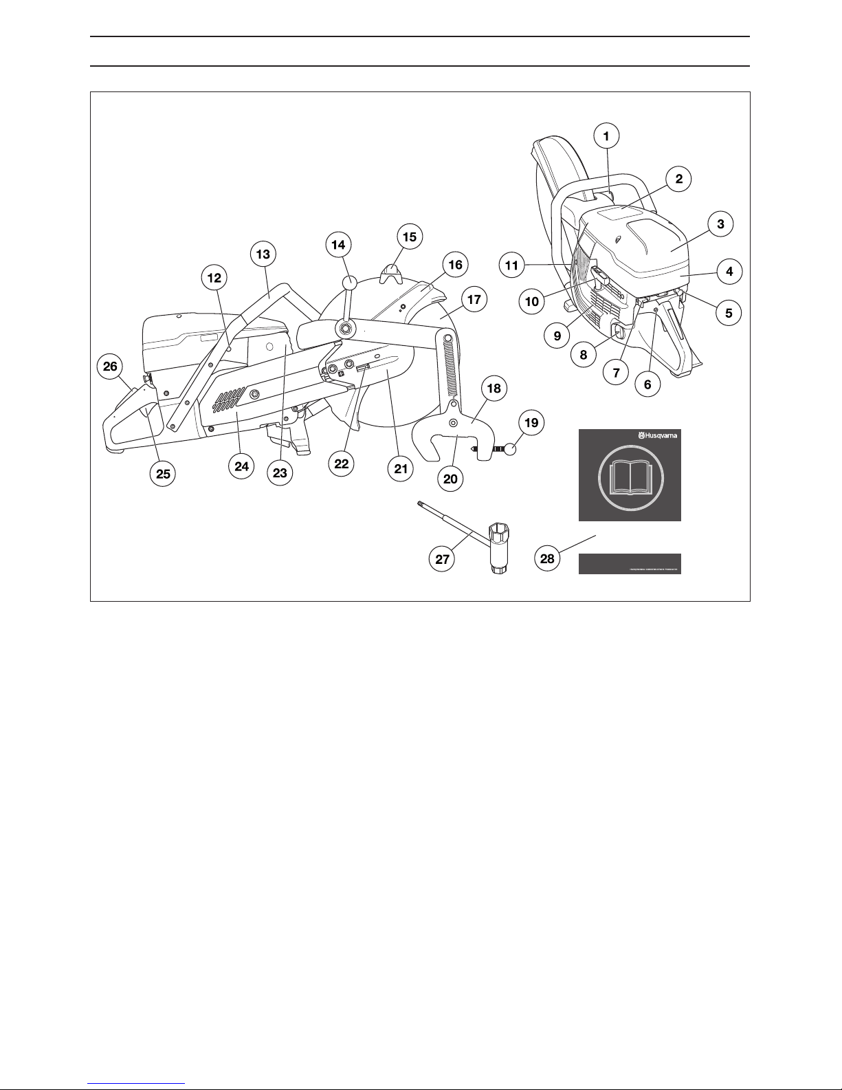
What is what on the power cutter - K 1260 Rail?
1 Mounting for rail fixture
2 Information and warning decal
3 Air filter cover
4 Cylinder cover
5 Choke control
6 Start throttle lock
7 Stop switch
8 Fuel tank
9 Starter
10 Starter handle
11 Rating plate
12 Decompression valve
13 Front handle
14 Power cutter lock handle
15 Adjustment handle for guard
16 Guard for the blade
17 Cutting blade
18 Rail fixture
19 Rail lock handle
20 Cutting guide
21 Cutting arm
22 Belt tensioner
23 Muffler
24 Cutting head
25 Throttle control
26 Throttle lockout
27 Combination spanner
28 Operator′s manual
Page 7
English – 7
MACHINE´S SAFETY EQUIPMENT
General
This section describes the machine´s safety equipment, its
purpose, and how checks and maintenance should be carried
out to ensure that it operates correctly.
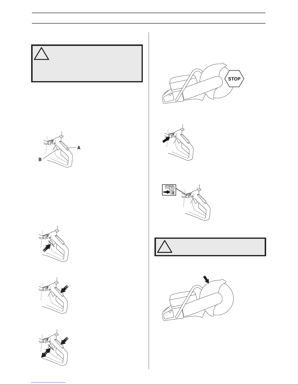
Throttle lockout
The throttle trigger lock is designed to prevent accidental
operation of the throttle. When the lock (A) is pressed in this
releases the throttle (B).
The trigger lock remains pressed in as long as the throttle is
pressed. When the grip on the handle is released the throttle
trigger and the throttle trigger lock both return to their original
positions. This is controlled by two independent return spring
systems. This means that the throttle trigger is automatically
locked in the idle position.
Checking the throttle lockout
• Make sure the throttle control is locked at the idle setting
when the throttle lockout is released.
• Press the throttle lockout and make sure it returns to its
original position when you release it.
• Check that the throttle control and throttle lockout move
freely and that the return springs work properly.
• Start the power cutter and apply full throttle. Release the
throttle control and check that the cutting blade stops and
remains stationary. If the cutting blade rotates when the
throttle is in the idle position you should check the
carburettor’s idle adjustment. See instructions in the
section "Maintenance".
Stop switch
Use the stop switch to switch off the engine.
Checking the stop switch
• Start the engine and make sure the engine stops when
you move the stop switch to the stop setting.
Guard for the blade
This guard is fitted above the cutting blade and is designed to
prevent parts of the blade or cutting fragments from being
thrown towards the user.
Checking the blade guard
• Check that the guard over the cutting blade is not cracked
or damaged in any other way. Replace when damaged.
• Check that the cutting blade is fitted correctly and does
not show signs of damage. A damaged cutting blade can
cause personal injury.
!
WARNING! Never use a machine that has
faulty safety equipment! If your machine
fails any of these checks contact your
service agent to get it repaired.
The engine should be switched off, and the
stop switch in STOP position.
!
WARNING! Always check that the guard is
correctly fitted before starting the machine.
Page 8
8 – English
MACHINE´S SAFETY EQUIPMENT
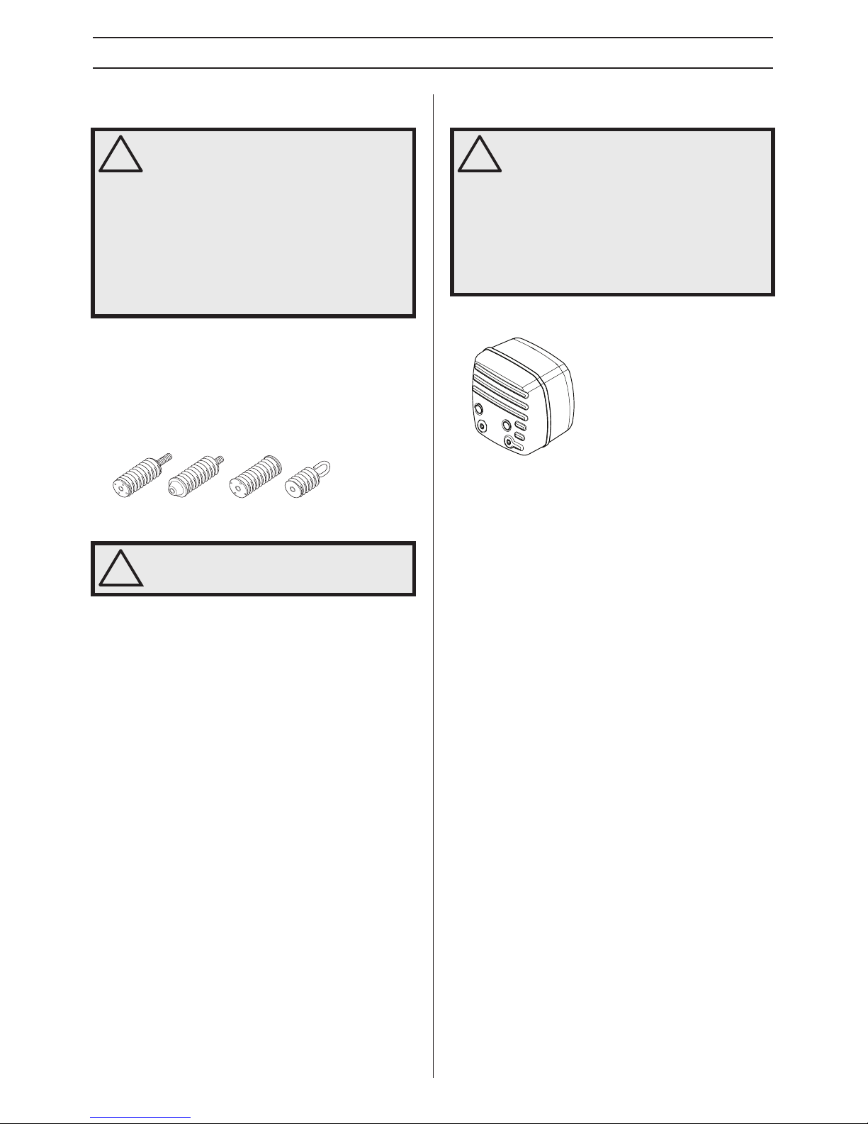
Vibration damping system
• Your machine is equipped with a vibration damping
system that is designed to minimize vibration and make
operation easier.
• The machine′s vibration damping system reduces the
transfer of vibration between the engine unit/cutting
equipment and the machine′s handle unit. The engine
body, including the cutting equipment, is insulated from
the handles by vibration damping units.
Checking the vibration damping system
• Check the vibration damping units regularly for cracks or
deformation. Replace them if damaged.
• Check that the vibration damping element is securely
attached between the engine unit and handle unit.
Muffler
The muffler is designed to keep noise levels to a minimum
and to direct exhaust fumes away from the user.
Inspecting the muffler
Check regularly that the muffler is complete and secured
correctly.
!
WARNING! Overexposure to vibration can
lead to circulatory damage or nerve damage
in people who have impaired circulation.
Contact your doctor if you experience
symptoms of overexposure to vibration.
Such symptoms include numbness, loss of
feeling, tingling, pricking, pain, loss of
strength, changes in skin colour or
condition. These symptoms normally appear
in the fingers, hands or wrists. These
symptoms may be increased in cold
temperatures.
!
WARNING! The engine should be switched
off, and the stop switch in STOP position.
!
WARNING! Never use a machine without a
muffler, or with a faulty muffler. A damaged
muffler may substantially increase the noise
level and the fire hazard. Keep fire fighting
equipment handy.
The muffler gets very hot during and after
use. This also applies during idling. Be
aware of the fire hazard, especially when
working near flammable substances and/or
vapours.
Page 9
English – 9
CUTTING BLADES
General
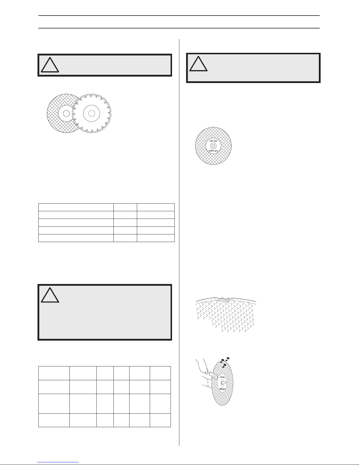
• Cutting blades are available in two basic designs;
abrasive baldes and diamond blades.
• High-quality blades are often most economical. Lower
quality blades often have inferior cutting capacity and a
shorter service life, which results in a higher cost in
relation to the quantity of material that is cut.
• Make sure that the right bushing is used for the cutting
blade to be fitted on the machine. See the instructions
under the heading Assembling the cutting blade.
Suitable cutting blades
*Without water
**Diamond blades for dry cutting
Cutting blades for different materials
Follow the instructions supplied with the cutting blade
concerning the suitability of the blade for various applications,
or consult your dealer in case of doubts.
* CAUTION! Only specialty blades.
Hand-held, high-speed machines
• Our cutting blades are manufactured for high-speed,
portable power cutters.
• Check that the blade is approved for the same or higher
speed according to the aproval plate of the engine. Never
use a cutting blade with a lower speed rating than that of
the power cutter.
Blade vibration
• The blade can become out-of-round and vibrate if an
excessive feed pressure is used.
• A lower feed pressure can stop the vibration. Otherwise
replace the blade.
Abrasive blades
• The cutting material on abrasive blades consists of grit
bonded using an organic binder. ”Reinforced blades” are
made up of a fabric or fibre base that prevents total
breakage at maximum working speed if the blade should
be cracked or damaged.
• A cutting blade’s performance is determined by the type
and size of abrasive corn, and the type and hardness of
the bonding agent.
• Ensure the blade it not cracked or damaged in any other
way.
• Test the abrasive blade by hanging it on your finger and
tapping it lightly with a screwdriver or the like. If the blade
does not produce a resonant, ringing sound it is damaged.
!
WARNING! A cutting blade may burst and
cause injury to the operator.
Cutting blades K 1260 K 1260 Rail
Abrasive blades Yes* Yes*
Abrasive blades for rail cutting No Ye s
Diamond blades Ye s Yes**
Toothed blads No No
!
WARNING! Never use a cutting blade for any
other materials than that it was intended for.
Cutting plastics with a diamond blade can
cause kickback when the material melts due
to the heat produced when cutting and
sticks to the blade. Never cut plastic
materials with a diamond blade!
Concrete Metal Rail Plastic
Cast
iron
Abrasive
blades
X X X X
Abrasive
blades for
rail cutting
X
Diamond
blades
X X* X*
!
WARNING! Never use a cutting blade at a
lower speed rating than that of the power
cutter. Only use cutting blades intended for
high speed handheld power cutters.
Page 10
10 – English
CUTTING BLADES
Abrasive blades for different materials
Rail cutting
Only use specially intended cutting blades for rail cutting.
Diamond blades
General
• Diamond blades consist of a steel core provided with
segments that contain industrial diamonds.
• Diamond blades ensure lower costs per cutting operation,
fewer blade changes and a constant cutting depth.
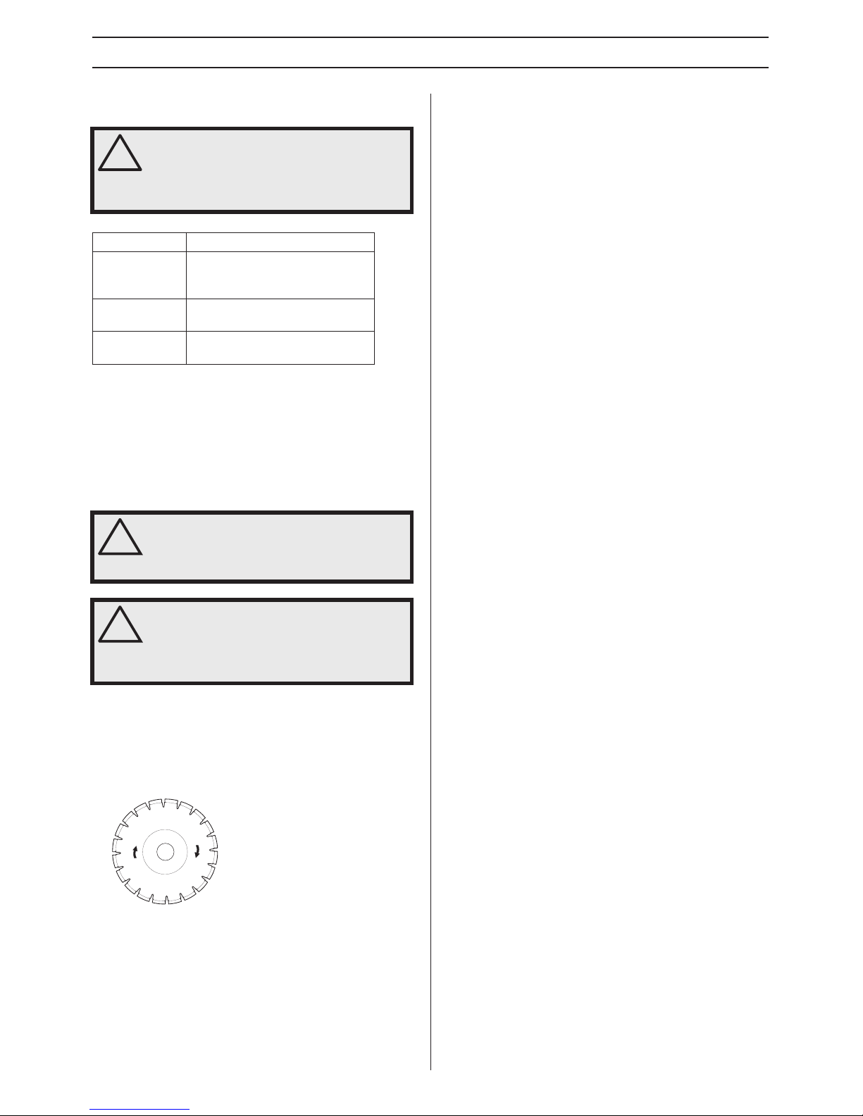
• When using diamond blades make sure that it rotates in
the direction indicated by the arrow on the blade.
Diamond blades for different materials
• Diamond blades are ideal for masonry, reinforced
concrete and other composite materials.
• Diamond blades are available in several hardness
classes.
• Special blades should be used when cutting metal. Ask
your dealer for help in choosing the right product.
Sharpening diamond blades
• Always use a sharp diamond blade.
• Diamond blades can become dull when the wrong feeding
pressure is used or when cutting certain materials such as
heavily reinforced concrete. Working with a blunt diamond
blade causes overheating, which can result in the
diamond segments coming loose.
• Sharpen the blade by cutting in a soft material such as
sandstone or brick.
Diamond blades for dry cutting
• Diamond blades for dry cutting can be used both with and
without water cooling.
• When dry cutting, lift the blade out from the cut every 30–
60 seconds and let it rotate in the air for 10 seconds to let
it cool. If this is not done, the blade may be overheated.
Diamond blades for wet cutting
• Diamond blades for wet cutting must be water cooled. If
this is not done, the blade may be overheated.
• Water cooling cools the blade and increases its service
life while also reducing the formation of dust.
Transport and storage
• Do not store or transport the power cutter with the cutting
blade fitted. All blades should be removed from the cutter
after use and stored carefully.
• Store cutting blades in dry, frost free conditions. Special
care should be taken with abrasive blades. Abrasive
blades must be stored on a flat, level surface. If an
abrasive blades is stored in humid conditions, this can
cause imbalance and result in injury.
• Inspect new blades for transport or storage damage.
!
WARNING! Do not use abrasive blades with
water. The strength is impaired when
abrasive blades are exposed to water or
moisture, which results in an increased risk
of the blade breaking.
Blade type Material
Concrete blade
Concrete, asphalt, stone masonry,
cast iron, aluminium, copper,
brass, cables, rubber, plastic, etc.
Metal blade
Steel, steel alloys and other hard
metals.
Blade for rail
cutting
Track
!
WARNING! Cutting plastics with a diamond
blade can cause kickback when the material
melts due to the heat produced when cutting
and sticks to the blade.
!
WARNING! Diamond blades get very hot
when used. An overheated blade is a result
of improper use, and may cause deformation
of the blade, resulting in damage and
injuries.
Page 11
English – 11
ASSEMBLING AND ADJUSTMENTS
General
Checking the drive shaft and flange
washers
When the blade is replaced with a new one, check the flange
washers and the drive shaft.
• Check that the threads on the drive shaft are undamaged.
• Check that the contact surfaces on the blade and the
flange washers are undamaged, of the correct dimension,
clean, and that they run properly on the drive axle.
• Do not use warped, notched, indented or dirty flange
washers. Do not use different dimensions of flange
washers.
Fitting the cutting blade
• Husqvarna’s blades are approved for hand-held power
cutters.
• Bushings can be fitted on the machine axle to adjust the
machine to the centre hole of the blade. Use a bushing
with the correct diameter! The blades are marked with the
diameter of the centre hole.
• When a diamond blade is mounted on the power cutter
make sure that the diamond blade will rotate in the
direction indicated by the arrow on the blade.
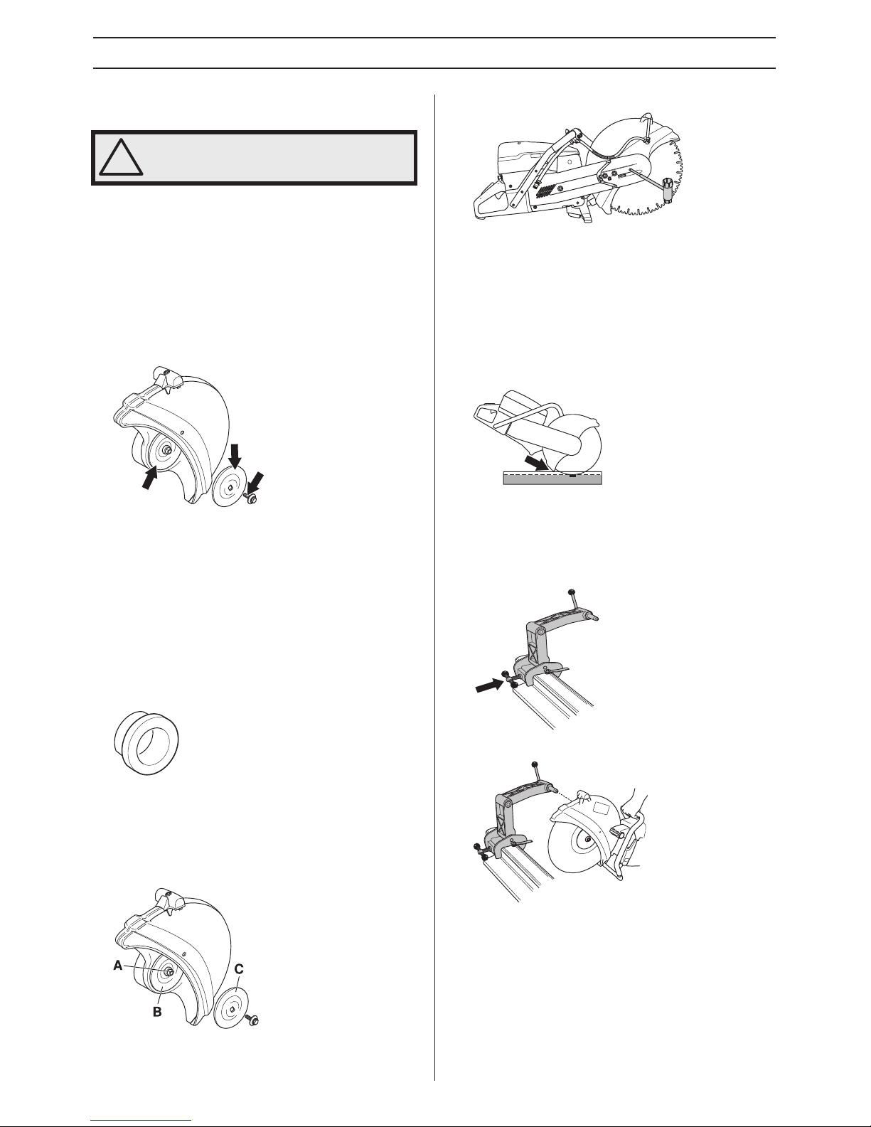
• The blade is placed on the bushing (A) between the inner
flange washer (B) and the flange washer (C). The flange
washer is turned so that it fits on the axle.
• Lock the shaft.
• Tightening torque for the bolt holding the blade is: 15-25
Nm (130-215 in.lb).
Guard for the blade
• The guard for the cutting equipment should be adjusted so
that the rear section is flush with the work piece. Spatter
and sparks from the material being cut are then collected
up by the guard and led away from the user. The guard
must always be fitted on the machine.
Assembling the rail fixture
(K 1260 Rail)
• Mount the rail fixture onto the rail. Screw the lock handle
tight.
Mount the power cutter with its right side to the fixture.
!
WARNING! The engine should be switched
off, and the stop switch in STOP position.
Page 12
12 – English
FUEL HANDLING
General
Fuel
Petrol
• Use good quality unleaded or leaded petrol.
• The lowest octane recommended is 90 (RON). If you run
the engine on a lower octane grade than 90 so-called
knocking can occur. This gives rise to a high engine
temperature, which can result in serious engine damage.
• When working at continuous high revs a higher octane
rating is recommended.
Environment fuel
The use of environmentl fuel (alkylate fuel), or environment
fuel for four-stroke engines blended with two-stroke oil as set
out below is recommended.
Two-stroke oil
• For best results and performance use HUSQVARNA twostroke engine oil, which is specially formulated for our aircooled two-stroke engines.
• Never use two-stroke oil intended for water-cooled
engines, sometimes referred to as outboard oil (rated
TCW).
• Never use oil intended for four-stroke engines.
Mixing
• Always mix the petrol and oil in a clean container intended
for fuel.
• Always start by filling half the amount of the petrol to be
used. Then add the entire amount of oil. Mix (shake) the
fuel mixture. Add the remaining amount of petrol.
• Mix (shake) the fuel mixture thoroughly before filling the
machine’s fuel tank.
• Do not mix more than one month’s supply of fuel at a time.
Mixing ratio
• 1:50 (2%) with HUSQVARNA two-stroke oil or equivalent.
• 1:33 (3%) with oils class JASO FB or ISO EGB formulated
for air-cooled, two-stroke engines.
Fuelling
Never start the machine:
• If you have spilt fuel or engine oil on the machine. Wipe off
the spill and allow the remaining fuel to evaporate.
• If you have spilt fuel on yourself or your clothes, change
your clothes. Wash any part of your body that has come in
contact with fuel. Use soap and water.
• If the machine is leaking fuel. Check regularly for leaks
from the fuel cap and fuel lines.
Transport and storage
• Store and transport the machine and fuel so that there is
no risk of any leakage or fumes coming into contact with
sparks or naked flames, for example, from electrical
machinery, electric motors, electrical relays/switches or
boilers.
• When storing and transporting fuel always use approved
containers intended for this purpose.
Long-term storage
• When storing the machine for long periods the fuel tank
must be emptied. Contact your local petrol station to find
out where to dispose of excess fuel.
!
WARNING! Running an engine in a confined
or badly ventilated area can result in death
due to asphyxiation or carbon monoxide
poisoning. Use fans to ensure proper air
circulation when working in trenches or
ditches deeper than one meter.
Fuel and fuel fumes are highly inflammable
and can cause serious injury when inhaled
or allowed to come in contact with the skin.
For this reason observe caution when
handling fuel and make sure there is
adequate ventilation.
The exhaust fumes from the engine are hot
and may contain sparks which can start a
fire. Never start the machine indoors or near
combustible material!
Do not smoke and do not place any hot
objects in the vicinity of fuel.
NOTICE! The machine is equipped with a two-stroke
engine and must always been run using a mixture of petrol
and two-stroke oil. It is important to accurately measure the
amount of oil to be mixed to ensure that the correct mixture
is obtained. When mixing small amounts of fuel, even small
inaccuracies can drastically affect the ratio of the mixture.
Petrol, litre Two-stroke oil, litre
2% (1:50) 3% (1:33)
5 0,10 0,15
10 0,20 0,30
15 0,30 0,45
20 0,40 0,60
!
WARNING! Always stop the engine and let it
cool for a few minutes before refuelling. The
engine should be switched off, and the stop
switch in STOP position.
When refuelling, open the fuel cap slowly so
that any excess pressure is released gently.
Clean the area around the fuel cap.
Tighten the fuel cap carefully after refuelling.
Negligence may lead to the start of a fire.
Move the machine at least 3 m from the
refuelling point before starting it.
Page 13
English – 13
OPERATING
Protective equipment
General
• Do not use the machine unless you are able to call for help
in the event of an accident.
Personal protective equipment
You must use approved personal protective equipment
whenever you use the machine. Personal protective
equipment cannot eliminate the risk of injury but it will reduce
the degree of injury if an accident does happen. Ask your
dealer for help in choosing the right equipment.
Always wear:
• Approved protective helmet
• Hearing protection
• Approved eye protection. If you use a face shield then you
must also wear approved protective goggles. Approved
protective goggles must comply with standard ANSI Z87.1
in the USA or EN 166 in EU countries. Visors must comply
with standard EN 1731.
• Breathing mask
• Heavy-duty, firm grip gloves.
• Tight-fitting, heavy-duty and comfortable clothing that
permits full freedom of movement.
• Boots with steel toe-caps and non-slip sole.
Other protective equipment
• Fire Extinguisher
• Always have a first aid kit nearby.
General safety precautions
This section describes basic safety directions for using the
machine. This information is never a substitute for
professional skills and experience.
• Please read the operator’s manual carefully and make
sure you understand the instructions before using the
machine.
• Keep in mind that it is you, the operator that is responsible
for not exposing people or their property to accidents or
hazards.
• The machine must be kept clean. Signs and stickers must
be fully legible.
Always use common sense
It is not possible to cover every conceivable situation you can
face. Always exercise care and use your common sense. If
you get into a situation where you feel unsafe, stop and seek
expert advice. Contact your dealer, service agent or an
experienced user. Do not attempt any task that you feel
unsure of!
!
WARNING! The use of products such as
cutters, grinders, drills, that sand or form
material can generate dust and vapours
which may contain hazardous chemicals.
Check the nature of the material you intend
to process and use an appropriate breathing
mask.
Long-term exposure to noise can result in
permanent hearing impairment. So always
use approved hearing protection. Listen out
for warning signals or shouts when you are
wearing hearing protection. Always remove
your hearing protection as soon as the
engine stops.
!
CAUTION! Sparks may appear and start a
fire when you work with the machine. Always
keep fire fighting equipment handy.
!
WARNING! The machine can be a dangerous
tool if used incorrectly or carelessly, which
can cause serious or fatal injury to the
operator or others.
Never allow children or other persons not
trained in the use of the machine to use or
service it.
Never allow anyone else to use the machine
without first ensuring that they have
understood the contents of the operator’s
manual.
Never use the machine if you are fatigued,
while under the influence of alcohol or
drugs, medication or anything that could
affect your vision, alertness, coordination or
judgement.
!
WARNING! Unauthorized modifications and/
or accessories may lead to serious injury or
death to the user or others. Under no
circumstances may the design of the
machine be modified without the permission
of the manufacturer.
Do not modify this product or use it if it
appears to have been modified by others.
Never use a machine that is faulty. Carry out
the checks, maintenance and service
instructions described in this manual. Some
maintenance and service measures must be
carried out by trained and qualified
specialists. See instructions under the
heading Maintenance.
Always use genuine accessories.
!
WARNING! This machine produces an
electromagnetic field during operation. This
field may under some circumstances
interfere with active or passive medical
implants. To reduce the risk of serious or
fatal injury, we recommend persons with
medical implants to consult their physician
and the medical implant manufacturer
before operating this machine.
Page 14
14 – English
OPERATING
Work area safety
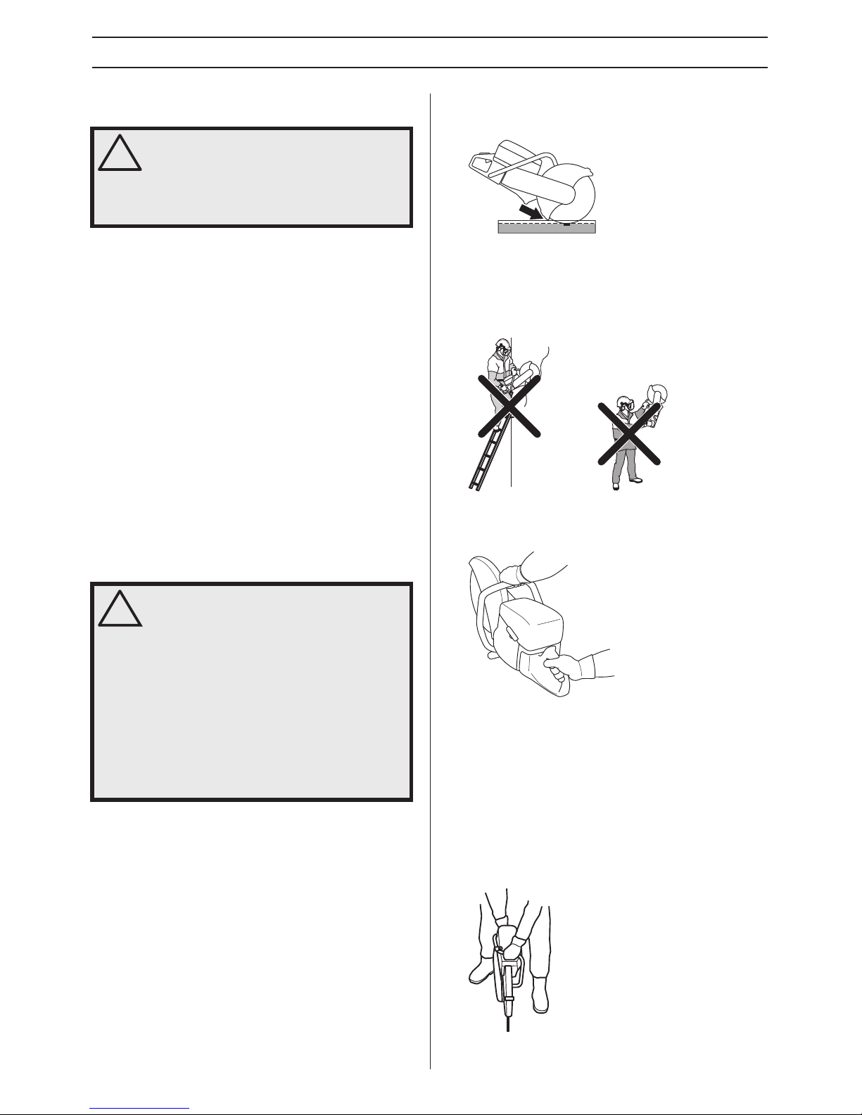
• Observe your surroundings to ensure that nothing can
affect your control of the machine.
• Ensure that no one/nothing can come into contact with the
cutting equipment or be hit by parts if the blade breaks.
• Do not use the machine in bad weather, such as dense
fog, heavy rain, strong wind, intense cold, etc. Working in
bad weather is tiring and can lead to dangerous
conditions, e.g. slippery surfaces.
• Never start to work with the power cutter before the
working area is clear and you have a firm foothold. Look
out for any obstacles with unexpected movement. Ensure
when cutting that no material can become loose and fall,
causing operating injury.Take great care when working on
sloping ground.
• Ensure that the working area is sufficiently illuminated to
create a safe working environment.
• Make sure that no pipes or electrical cables are routed in
the working area or in the material to be cut.
Basic working techniques
• The machine is designed and intended for cutting with
abrasive blades or diamond blades intended for high
speed handheld machines. The machine shall not be
used with any other type of blade, or for any other type of
cutting.
• Maintain a safe distance from the cutting blade when the
engine is running.
• Never move the machine when the cutting equipment is
rotating.
• The guard for the cutting equipment should be adjusted so
that the rear section is flush with the work piece. Spatter
and sparks from the material being cut are then collected
up by the guard and led away from the user. The guards
for the cutting equipment must always be fitted when the
machine is running.
• Never use the kickback zone of the blade for cutting. See
instructions under the heading "Kickback".
• Keep a good balance and a firm foothold.
• Never cut above shoulder height. Never cut from a ladder.
Use a platform or scaffold when working at high altitude.
• Always hold the machine in a firm grip with both hands.
Hold it so that the thumbs and fingers grip round the
handles.
• Stand at a comfortable distance from the work piece.
• Check that the blade is not in contact with anything when
the machine is started
• Apply the cutting blade gently with high rotating speed (full
throttle) Maintain full speed until cutting is complete.
• Let the machine work without forcing or pressing the
blade.
• Feed down the machine in line with the blade. Pressure
from the side can damage the blade and is very
dangerous.
!
WARNING! The safety distance for the power
cutter is 15 metres. You are responsible to
ensure that animals and onlookers are not
within the working area. Do not start cutting
until the working area is clear and you are
standing firmly.
!
WARNING! Do not pull the power cutter to
one side, this can cause the blade to jam or
break resulting in injury to people.
Under all circumstances avoid grinding
using the side of the blade; it will almost
certainly be damaged, break and can cause
immense damage. Only use the cutting
section.
Cutting plastics with a diamond blade can
cause kickback when the material melts due
to the heat produced when cutting and
sticks to the blade. Never cut plastic
materials with a diamond blade!
Page 15
English – 15
OPERATING
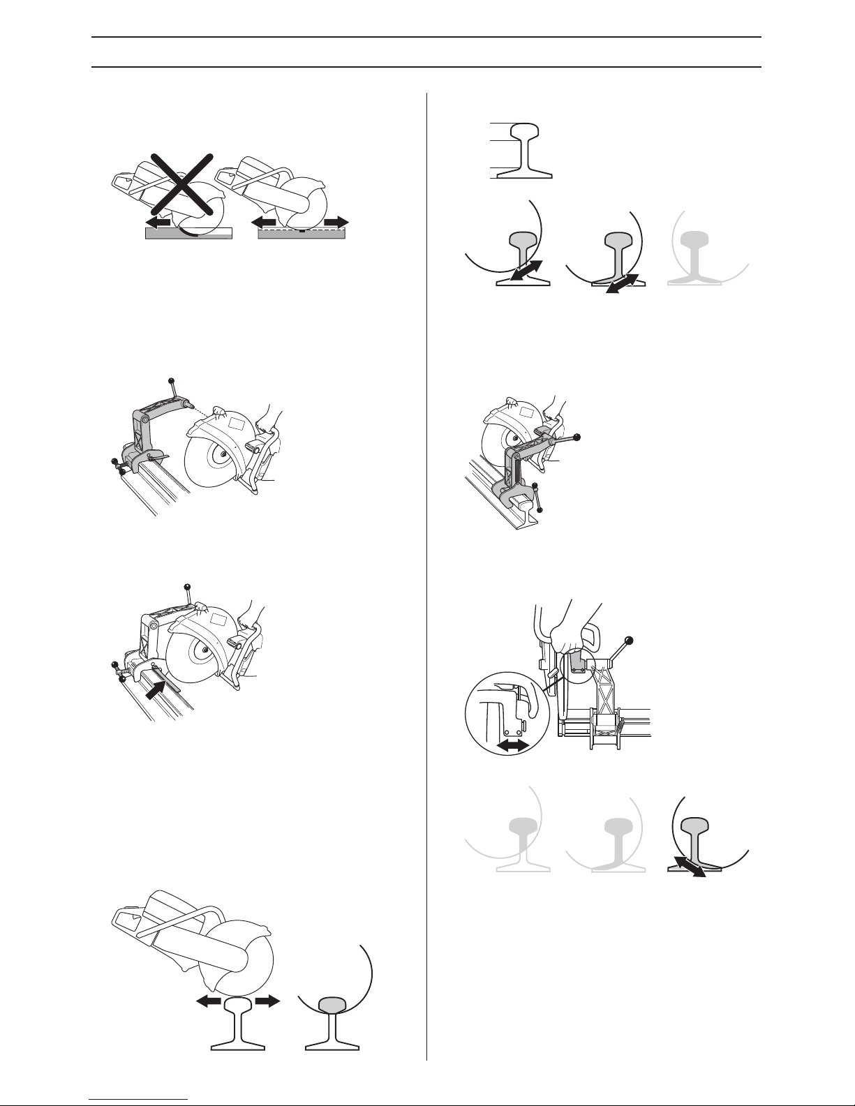
• Move the blade slowly forwards and backwards to achieve
a small contact area between the blade and the material
to be cut. This reduces the temperature of the blade and
ensures effective cutting.
Rail cutting
Cutting guide
The cutting guide is used to facilitate guiding the blade to
where the cut is to be made. The first time you use the power
cutter, you must cut the guide.
• Fit fixture and power cutter.
• Fold out the cutting guide.
• Fix the cutting guide parallel to the rail in an appropriate
manner.
• Carefully cut off the guide.
Work procedure
• Fold out the cutting guide.
• Align the saw cut and fold in the guide.
• Begin the cutting process by swinging the machine back
and forth horizontally. This way the cutting blade’s contact
surface to the rail is minimised, which reduces the risk of
the blade glazing.
• When you have cut through the head (A), you continue
cutting the rib (B) and foot (C).
If the cut cannot be completed from one side, the power cutter
must be turned around.
• Shut off the machine.
• Dismantle the power cutter from the fixture.
• Fit the power cutter with its left side to the rail fixture.
• Guide the cutting blade down towards the rail and check
that the cutting blade is centred in the cut. If necessary,
adjust the movable bushing so that the blade ends up
centred in the middle of the cut.
• Now cutting can proceed.
General tips
• Only use specially intended cutting blades for rail cutting.
• Apply the cutting blade gently with high rotating speed (full
throttle) Maintain full speed until cutting is complete.
• Hold the machine’s handle so that the hands are in line
with the cutting blade. This to achieve maximum cutting
speed, blade service life and a straight cut.
• When performing the cutting process correctly, it takes
about one minute to cut a 50 kg/m-rail. If it takes longer,
review your cutting technique. Problems which arise are
often the result of incorrect cutting technique.
A
B
C
Page 16
16 – English
OPERATING
Kickback
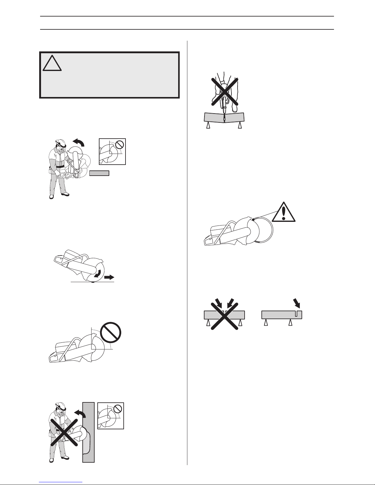
Kickback is the sudden upward motion that can occur if the
blade is pinched or stalled in the kickback zone. Most
kickbacks are small and pose little danger. However a
kickback can also be very violent and throw the power cutter
up and back towards the user in a rotating motion causing
serious or even fatal injury.
Reactive force
A reactive force is always present when cutting. The force
pulls the machine in the opposite direction to the blade
rotation. Most of the time this force is insignificant. If the blade
is pinched or stalled the reactive force will be strong and you
might not be able to control the power cutter.
Kickback zone
Never use the kickback zone of the blade for cutting. If the
blade is pinched or stalled in the kickback zone, the reactive
force will push the power cutter up and back towards the user
in a rotating motion causing serious or even fatal injury.
Climbing kickback
If the kickback zone is used for cutting the reactive force
drives the blade to climb up in the cut. Do not use the
kickback zone. Use the lower quadrant of the blade to avoid
climbing kickback.
Pinching kickback
Pinching is when the cut closes and pinches the blade. If the
blade is pinched or stalled the reactive force will be strong and
you might not be able to control the power cutter.
If the blade is pinched or stalled in the kickback zone, the
reactive force will push the power cutter up and back towards
the user in a rotating motion causing serious or even fatal
injury.
Pipe cutting and pinching
Special care should be taken whet cutting in pipes. If the pipe
is not properly supported and the cut kept open through out
the cut the blade might be pinched in the kickback zone and
cause a severe kickback.
How to aviod kickback
Avoiding kickback is simple.
• The work piece must always be supported so that the cut
stays open when cutting through. When the cut opens
there is no kickback. If the cut closes and pinches the
blade ther is always a risk of kickback.
• Take care when inserting the blade in an existing cut.
• Be alert to movement of the work piece or anything else
that can occur, which could cause the cut to close and
pinch the blade.
Transport and storage
• Secure the equipment during transportation in order to
avoid transport damage and accidents.
• For transport and storage of cutting blades, see the
section "Cutting blades".
• For transport and storage of fuel, see the section "Fuel
handling".
• Store the equipment in a lockable area so that it is out of
reach of children and unauthorized persons.
!
WARNING! Kickbacks are sudden and can
be very violent. The power cutter can be
thrown up and back towards the user in a
rotating motion causing serious or even fatal
injury. It is vital to understand what causes
kickback and how to avoid it before using
the machine.
Page 17
English – 17
STARTING AND STOPPING
Before starting
• Perform daily maintenance. See instructions in the section
"Maintenance".
Starting
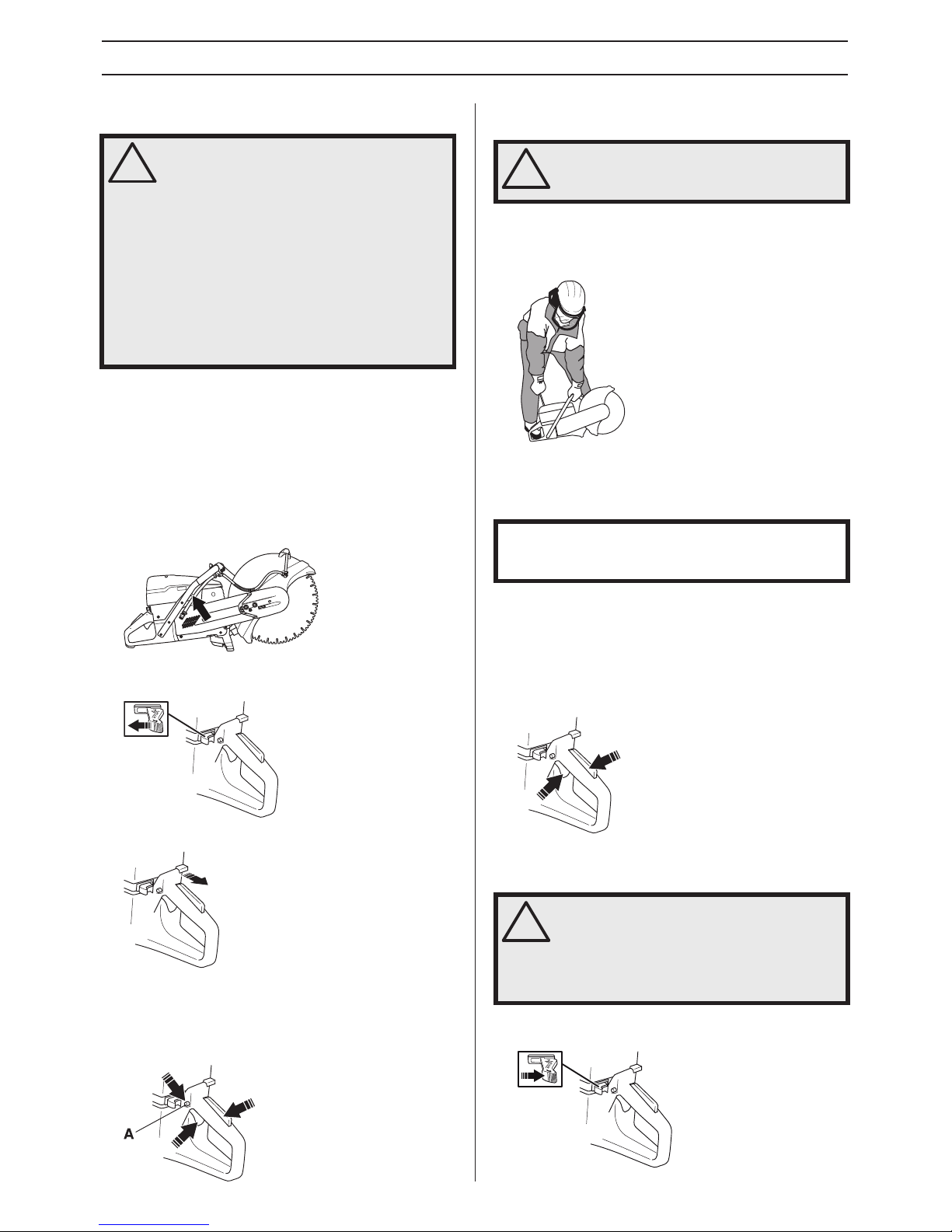
• Decompression valve: Press in the valve to reduce the
pressure in the cylinder, this is to assist starting the power
cutter. The decompression valve should always be used
when starting. The valve automatically returns to its initial
position when the machine starts.
• Stop switch: Make sure that the stop switch (STOP) is in
the left position.
• Choke - cold engine: Pull the choke control fully out.
• Start throttle position: Press in the throttle trigger lock,
throttle control and then the start throttle lock (A). Release
the throttle control and it is locked in the half throttle
position. The lock releases when the throttle control is
pressed in fully.
Start the engine
• Grip the front handle with your left hand. Put your right foot
on the lower section of the rear handle pressing the
machine against the ground. Never twist the starter
cord around your hand.
• Grip the starter handle, slowly pull out the cord with your
right hand until you feel some resistance (the starter pawls
grip), now quickly and powerfully pull the cord.
• With a cold engine: The machine stops when the engine
fires becase the chokel control is pulled out.
Press the choke control and the decompression valve.
Pull the starter handle until the engine starts.
• When the engine starts, quickly apply full throttle to
automatically disengage fast idle.
Stopping
• Stop the engine by moving the stop switch (STOP) to the
right.
!
WARNING! Please read the operator’s
manual carefully and make sure you
understand the instructions before using the
machine.
Wear personal protective equipment. See
instructions under the heading ”Personal
protective equipment”.
Make sure no unauthorised persons are in
the working area, otherwise there is a risk of
serious personal injury.
Check that the fuel cap is properly secured,
and that there is no fuel leakage. Risk of fire.
!
WARNING! The cutting blade rotates when
the engine is started. Make sure it can rotate
freely.
NOTICE! Do not pull the starter cord all the way out and do
not let go of the starter handle when the cord is fully
extended. This can damage the machine.
!
CAUTION! The cutting blade continues to
rotate up to a minute after the motor has
stopped. (Blade coasting.) Make sure that
the cutting blade can rotate freely until it is
completely stopped. Carelessness can
result in serious personal injury.
Page 18
18 – English
MAINTENANCE
General
• Let your Husqvarna dealer regularly check the machine and make essential adjustments and repairs.
Maintenance schedule
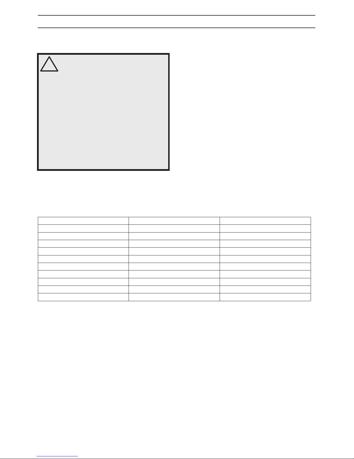
In the maintenance schedule you can see which parts of your machine that require maintenance, and with which intervals it should
take place. The intervals are calculated based on daily use of the machine, and may differ depending on the rate of usage.
*See instructions in the section "Machine’s safety equipment".
** See instructions in the section "Cutting blades" and "Assembly and settings".
!
WARNING! The user must only carry out the
maintenance and service work described in
this Operator’s Manual. More extensive work
must be carried out by an authorized service
workshop.
The engine should be switched off, and the
stop switch in STOP position.
Wear personal protective equipment. See
instructions under the heading ”Personal
protective equipment”.
The life span of the machine can be reduced
and the risk of accidents can increase if
machine maintenance is not carried out
correctly and if service and/or repairs are
not carried out professionally. If you need
further information please contact your
nearest service workshop.
Daily maintenance Weekly maintenance Monthly maintenance
Cleaning Cleaning Cleaning
External cleaning Spark plug
Cooling air intake Fuel tank
Functional inspection Functional inspection Functional inspection
General inspection Vibration damping system* Fuel system
Throttle lockout* Muffler* Air filter
Stop switch* Drive belt Drive gear, clutch
Guard for the blade* Carburettor
Cutting blade** Starter
Page 19
English – 19
MAINTENANCE
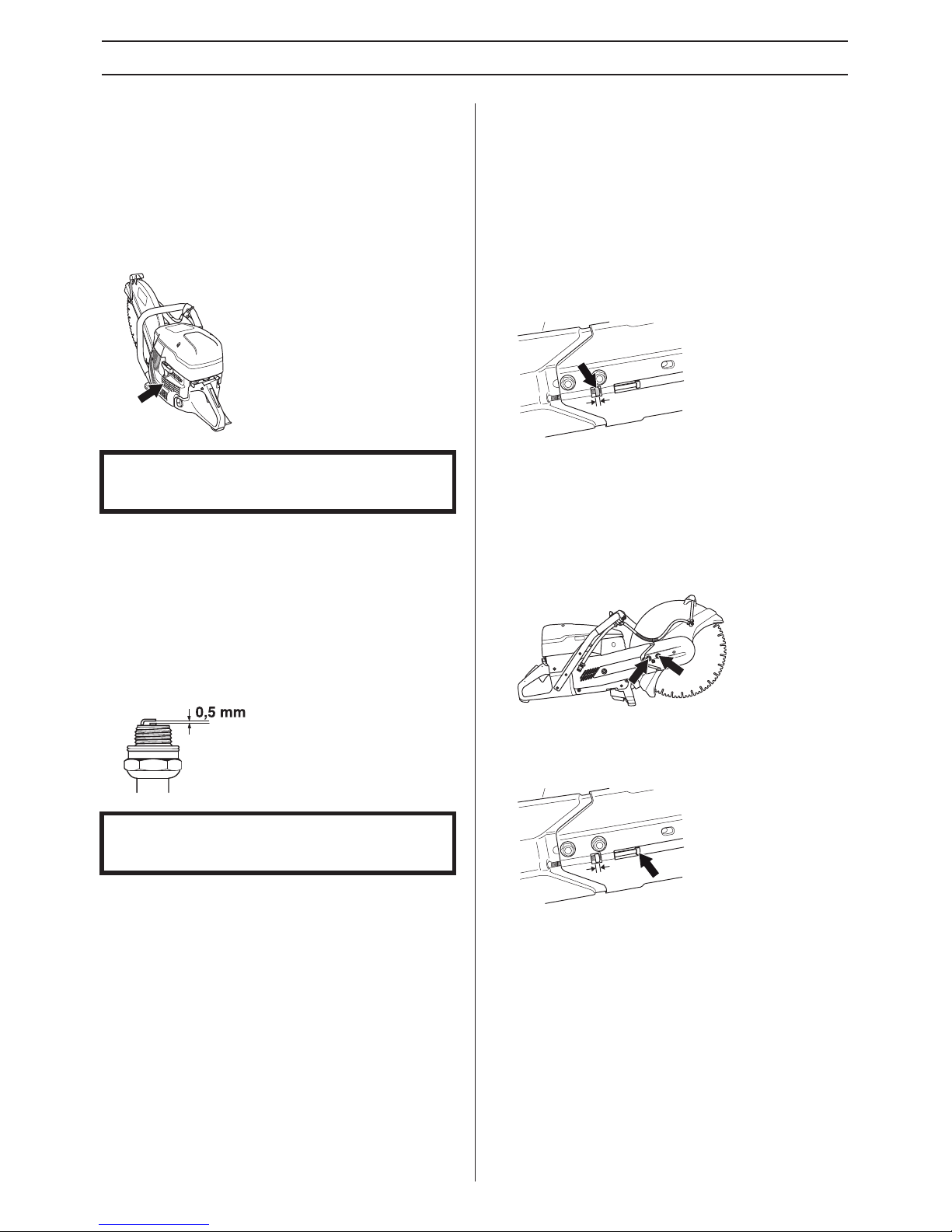
Cleaning
External cleaning
• Clean the machine daily by rinsing it with clean water after
the work is finished.
Cooling air intake
• Clean the cooling air intake when needed.
Spark plug
• If the machine is low on power, difficult to start or runs
poorly at idle speed: always check the spark plug first
before taking other steps.
• Ensure that the spark plug cap and ignition lead are
undamaged to avoid the risk of electric shock.
• If the spark plug is dirty, clean it and at the same time
check that the electrode gap is 0.5 mm. Replace if
necessary.
These factors cause deposits on the spark plug electrodes,
which may result in operating problems and starting
difficulties.
• An incorrect fuel mixture (too much or incorrect type of
oil).
• A dirty air filter.
Functional inspection
General inspection
• Check that nuts and screws are tight.
Drive belt
Check the tension of the drive belt
• For correct tensioning of the drive belt, the square nut
should be positioned opposite the marking on the belt
cover.
Tensioning the drive belt
• The tension of a new drive belt must be readjusted after
one or two tanks of fuel have been used.
• The drive belt is enclosed and well protected from dust
and dirt.
• When the drive belt is to be tensioned, release the bolts
holding the cutting arm.
• Screw the adjuster screw so that the square headed nut
comes opposite the marking on the cover. This
automatically ensures that the belt has the correct
tension.
• Tighten both of the screws holding the cutting head using
a T-wrench.
NOTICE! A dirty or blocked air intake results in the machine
overheating which causes damage to the piston and
cylinder.
NOTICE! Always use the recommended spark plug type!
Use of the wrong spark plug can damage the piston/
cylinder.
Page 20
20 – English
MAINTENANCE
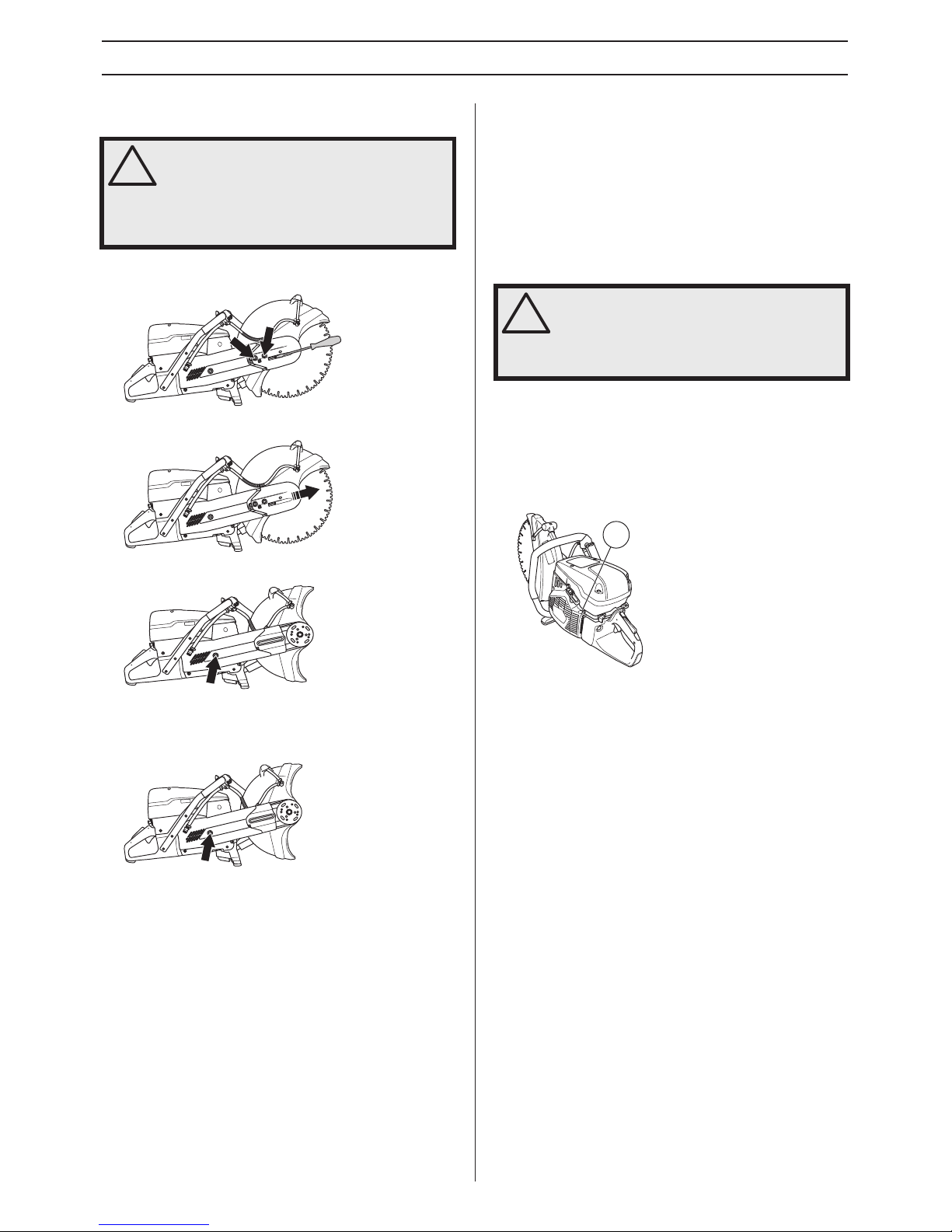
Replacing the drive belt
• First release the two bolts and then the adjuster screw to
release the belt tension.
• Now unscrew the bolts and dismantle the belt guard.
• Remove the belt from the belt pulley.
• The cutting head is now loose and can be removed from
the machine.
• Remove the nut. Remove the side cover.
• Replace the drive belt.
• Assemble in the reverse order as set out for dismantling.
Carburettor
The carburettor is equipped with fixed needles to ensure the
machine always receives the correct mixture of fuel and air.
When the engine lacks power or accelerates poorly, do the
following:
• Check the air filter and replace if necessary. When this
does not help, contact an authorised service workshop.
Adjusting the idle speed
Start the engine and check the idling setting. When the
carburettor is set correctly the cutting blade should be still
while engine is idling.
• Adjust the idle speed using the T screw. When an
adjustment is necessary, first turn the screw clockwise
until the blade starts to rotate. Now turn the screw anticlockwise until the blade stops rotating.
Rec. idle speed: 2500 rpm
!
WARNING! Never start the engine when the
belt pulley and clutch are removed for
maintenance. Do not start the machine
without the cutting arm or cutting head
fitted. Otherwise the clutch could come
loose and cause personal injuries.
!
CAUTION! If the idle speed cannot be
adjusted so that the cutting attachment
stops, contact your dealer/service
workshop. Do not use the machine until it
has been correctly adjusted or repaired.
T
Page 21
English – 21
MAINTENANCE
Starter
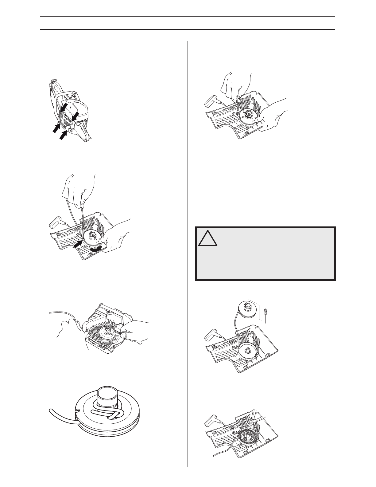
Checking the starter cord
• Loosen the screws that hold the starter against the
crankcase and remove the starter.
• Pull the cord out about 30 cm and lift it into the cut-out in
the periphery of the starter pulley. When the cord is intact:
Release the spring tension by letting the pulley rotate
slowly backwards.
Changing a broken or worn starter cord
• Remove any remnants of the old starter cord and check
that the return spring works. Insert the new starter cord
through the hole in the starter housing and in the cord
pulley.
• Secure the starter cord around the cord pulley as
illustrated. Tighten the fastening well and ensure that the
free end is as short as possible. Secure the end of the
starter cord in the starter handle.
Tensioning the recoil spring
• Guide the cord through the cut-out in the periphery of the
pulley and wind the cord 3 times clockwise around the
centre of the starter pulley.
• Now pull the starter handle and in doing so tension the
spring. Repeat the procedure once more, but this time
with four turns.
• Note that the starter handle is drawn to its correct home
position after tensioning the spring.
• Check that the spring is not drawn to its end position by
pulling out the starter line fully. Slow the starter pulley with
your thumb and check that you can turn the pulley at least
a further half turn.
Changing a broken recoil spring
• Undo the bolt in the centre of the pulley and remove the
pulley.
• Carefully lift the cover that protects the spring. Bear in
mind that the return spring lies tensioned in the starter
housing.
• Carefully remove the spring using pilers.
!
WARNING! When the recoil spring is wound
up in the starter housing it is under tension
and can, if handled carelessly, pop out and
cause personal injury.
Always be careful when changing the recoil
spring or the starter cord. Always wear
protective goggles.
Page 22
22 – English
MAINTENANCE
• Lubricate the recoil spring with light oil. Fit the pulley and
tension the recoil spring.
Fitting the starter
• To fit the starter, first pull out the starter cord and place the
starter in position against the crankcase. Then slowly
release the starter cord so that the pulley engages with
the pawls.
• Tighten the screws.
Fuel system
General
• Check that the fuel cap and its seal are not damaged.
• Check the fuel hose. Replace when damaged.
Fuel filter
• The fuel filter sits inside the fuel tank.
• The fuel tank must be protected from contamination when
filling. This reduces the risk of operating disturbances
caused by blockage of the fuel filter located inside the
tank.
• The filter cannot be cleaned but must be replaced with a
new filter when it is clogged. The filter should be
changed at least once per year.
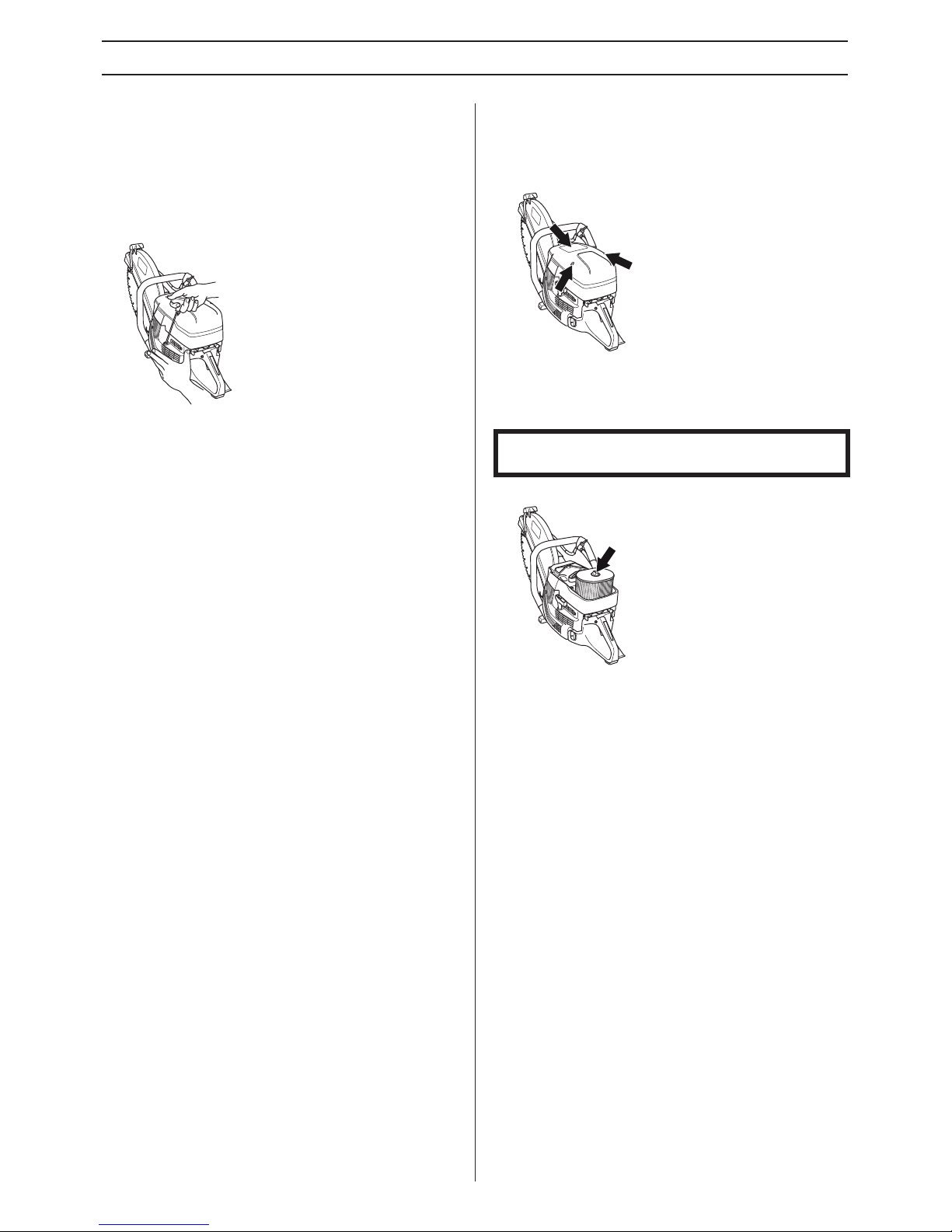
Air filter
The air filter only needs to be checked if the engine drops in
power.
• Loosen the screws. Remove the air filter cover.
• Check the air filter and replace if necessary.
Replacing the air filter
• Loosen the screw.
• Replace the air filter.
Drive gear, clutch
• Check the clutch centre, drive gear and clutch spring for
wear.
NOTICE! The air filter must not be cleaned or blown clean
with compressed air. This will damage the filter.
Page 23

English – 23
TECHNICAL DATA
Technical data
Note 1: Noise emissions in the environment measured as sound power (LWA) in conformity with EC directive 2000/14/EC.
Note 2: Equivalent sound pressure level, according to EN ISO 19432, is calculated as the time-weighted energy total for different
sound pressure levels under various working conditions. Reported data for equivalent sound pressure level for the machine has a
typical statistical dispersion (standard deviation) of 1 dB (A).
Note 3: Equivalent vibration level, according to EN ISO 19432, is calculated as the time-weighted energy total for vibration levels
under various working conditions. Reported data for equivalent vibration level has a typical statistical dispersion (standard
deviation) of 1 m/s2.
Cutting equipment
Engine K 1260 K 1260 Rail
Cylinder displacement, cm
3
119 119
Cylinder bore, mm 60 60
Stroke, mm 42 42
Idle speed, rpm 2700 2700
Recommended max. speed, rpm 9300 (+/- 150) 9300 (+/- 150)
Power, kW/ rpm 5,8/9000 5,8/9000
Ignition system
Manufacturer of ignition system SEM SEM
Type of ignition system CD CD
Spark plug
Champion RCJ 6Y/
NGK BPMR 7A
Champion RCJ 6Y/
NGK BPMR 7A
Electrode gap, mm 0,5 0,5
Fuel and lubrication system
Manufacturer of carburettor Walbro Walbro
Carburettor type WG 9A WG 9A
Fuel tank capacity, litre 1,25 1,25
Weight
Power cutter without fuel and cutting blade, kg
14” (350 mm) 13,6 15,2
16” (400 mm) 14,4 15,9
Rail fixture, kg
RA 10 5,3
RA 10 S 5,7
Noise emissions (see note 1)
Sound power level, measured dB(A) 116 116
Sound power level, guaranteed LWA dB(A) 117 117
Sound levels (see note 2)
Equivalent sound pressure level at the operator’s ear,
dB(A)
104 104
Equivalent vibration levels, a
hveq
(see note 3) 14” (350 mm) 16” (400 mm)
Front handle, m/s
2
3,3 3,6
Rear handle, m/s
2
3,5 4,1
Cutting blade Max. peripheral speed, m/s Max. speed of output shaft, rpm
14” (350 mm) 100 5400
16” (400 mm) 100 4700
Page 24

24 – English
TECHNICAL DATA
EC-declaration of conformity
(Applies to Europe only)
Husqvarna AB, SE-561 82 Huskvarna, Sweden, tel +46-36-146500, declares under sole responsibility that the power cutters
Husqvarna K 1260, K 1260 Rail from 2010’s serial numbers and onwards (the year is clearly stated in plain text on the rating plate
with subsequent serial number), complies with the requirements of the COUNCIL’S DIRECTIVES:
• of May 17, 2006 "relating to machinery" 2006/42/EC
• of December 15, 2004 ”relating to electromagnetic compatibility” 2004/108/EC.
• of May 8, 2000 ”relating to the noise emissions in the environment” 2000/14/EC.
For information relating to noise emissions, see the chapter Technical data.
Notified body: 0404, SMP Svensk Maskinprovning AB, Fyrisborgsgatan 3, SE-754 50 Uppsala, Sweden, has carried out the
assessment of conformity in accordance with annex V of the Directive 2000/14/EC.
The certificate has the number: 01/169/030.
The following standards have been applied: EN ISO 12100:2003, CISPR 12:2007, EN ISO 19432:2008.
Gothenburg 11 October 2010
Henric Andersson
Vice President, Head of Power Cutters and Construction Equipment
Husqvarna AB
(Authorized representative for Husqvarna AB and responsible for technical documentation.)
Page 25

Page 26

´®z+TN|¶64¨
´®z+TN|¶64¨
Page 27

Page 28

´®z+TN|¶64¨
2010-10-08
´®z+TN|¶64¨
1152469-26
Original instructions
 Loading...