

Page 1

Repair Parts Manual
GTH3052TDF / 96041028500
580 78 80-28 Rev. 6
Please read the operator’s manual carefully and make sure
you understand the instructions before using the machine.
English
Page 2

HOW TO USE THIS MANUAL
This manual is designed to provide the customer with a means to identify the parts on his/her tractor
when ordering repair parts. The illustrations may or may not represent the actual assemblies; therefore,
it is not recommended to use this manual as a guide to assemble or disassemble the tractor. Some
hardware and parts are drawn larger in order to more readily identify them.
Each tractor has its own model number.
The model number for your tractor can be found on the fender under the seat.
When ordering parts, always give the following information:
• Product - “TRACTOR”
• MODEL NUMBER - “GTH3052TDF" (96041028500)”
• Part Number
• Part Description
TABLE OF CONTENTS
SCHEMATIC ................................................................................................................ 3
ELECTRICAL ............................................................................................................ 4-5
CHASSIS ..................................................................................................................6-7
DRIVE........................................................................................................................8-9
ENGINE ................................................................................................................. 10-11
STEERING ............................................................................................................12-13
MOWER DECK .....................................................................................................14-15
MOWER LIFT ............................................................................................................. 16
SEAT .......................................................................................................................... 17
DECALS ..................................................................................................................... 18
WARRANTY ..........................................................................................................19-22
2
Page 3
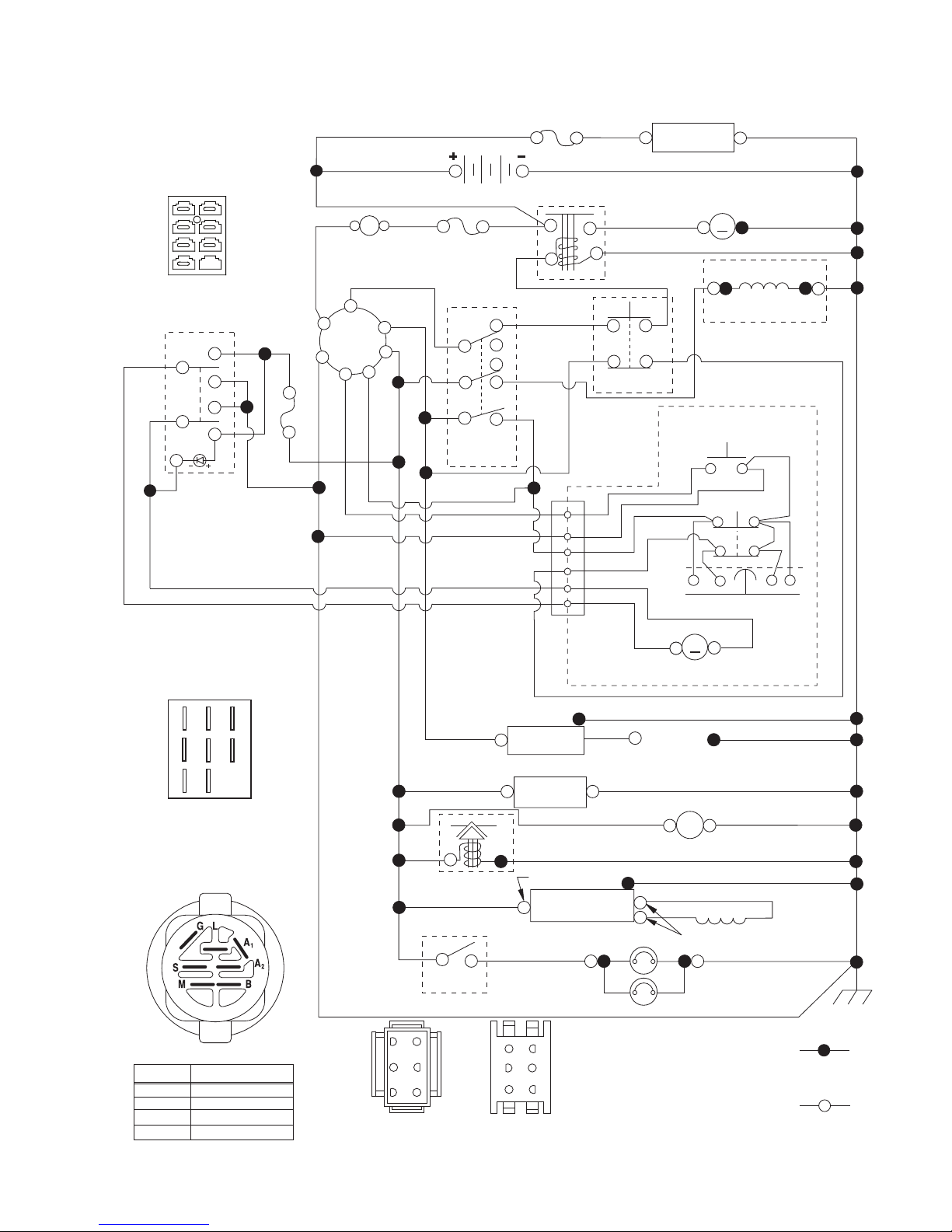
TRACTOR - MODEL NO. GTH3052TDF (96041028500), PRODUCT NO. 960 41 02-85
SCHEMATIC
SCH27
CHARGE
FUSE
INDICATOR
(OPTIONAL)
3
2
1
7
ELECTRIC DIFFERENTIAL
SWITCH CONNECTOR
5
4
6
LED
SWITCH
1
3
RED
BLACK
2
7
ELECTRIC DIFFERENTIAL
BATTERY
6
B
G
L
A
AMMETER
(OPTIONAL)
S
M
A1
A2
WHITE
RED
RED
FUSE
PTO SWITCH
(DISENGAGED)
C
A
B
BLACK /WHITE
BLACK/WHITE
GREEN
YELLOW
BLACK
5
4
BLUE
FUSE
BLUE
BLACK
RED
H
D
E
WHITE
RED
GREEN
SOLENOID
2
3
1
6
4
5
JUNCTION
CONNECTOR
BLACK
WHITE
CLUTCH/BRAKE
(PEDAL UP)
BLACK
GREEN
GRAY
RED
BLACK
STARTER
M
M
ELECTRIC CLUTCH
REVERSE SWITCH
(NOT IN REVERSE)
YELLOW
ELECTRIC DIFFERENTIAL
(NOT OCCUPIED)
SHORTING
M
M
ACTUATOR
SEAT SWITCH
GRAY
CHASSIS
HARNESS
CONNECTOR
BLACK
B
A
PTO SWITCH
(MATING SIDE)
IGNITION SWITCH
CIRCUITPOSITION
OFF
RUN/OVERRIDE
M+G+A1
B+S+A1START
FC
E
D
B+A1
B+A1RUN
H
G
“MAKE”
L+A2
BLACK
BLUE
ORANGE
SWITCH
3
6
52
41
CHASSIS HARNESS
CONNECTOR
(MATING SIDE)
BLUE
FUEL
LINE
FUEL SHUT-OFF
SOLENOID
(IF EQUIPPED)
RED
LIGHT
DASH HARNESS
CONNECTOR
IGNITION
UNIT
(OPTIONAL)
HOUR
METER
BLUE
CHARGING SYSTEM OUTPUT
9-16AMPDC@3600 RPM
REGULATOR
BROWN
6
3
5
2
4
1
SPARK
PLUGS GAP
(2 PLUGS ON
TWIN CYL. ENGINES)
BLACK
12V
POWER OUTLET
(OPTIONAL)
BLACK
STATOR
28 VOLTS AC @ 3600 RPM (REGULATOR DISCONNECTED)
BLACK
HEADLIGHTS
WIRING INSULATED CLIPS
NOTE: IF WIRING INSULATED
CLIPS WERE REMOVED FOR
SERVICING OF UNIT, THEY
SHOULD BE RE-INSTALLED TO
PROPERLY SECURE YOUR
WIRING.
NON-REMOVABLE
CONNECTIONS
REMOVABLE
CONNECTIONS
3
Page 4
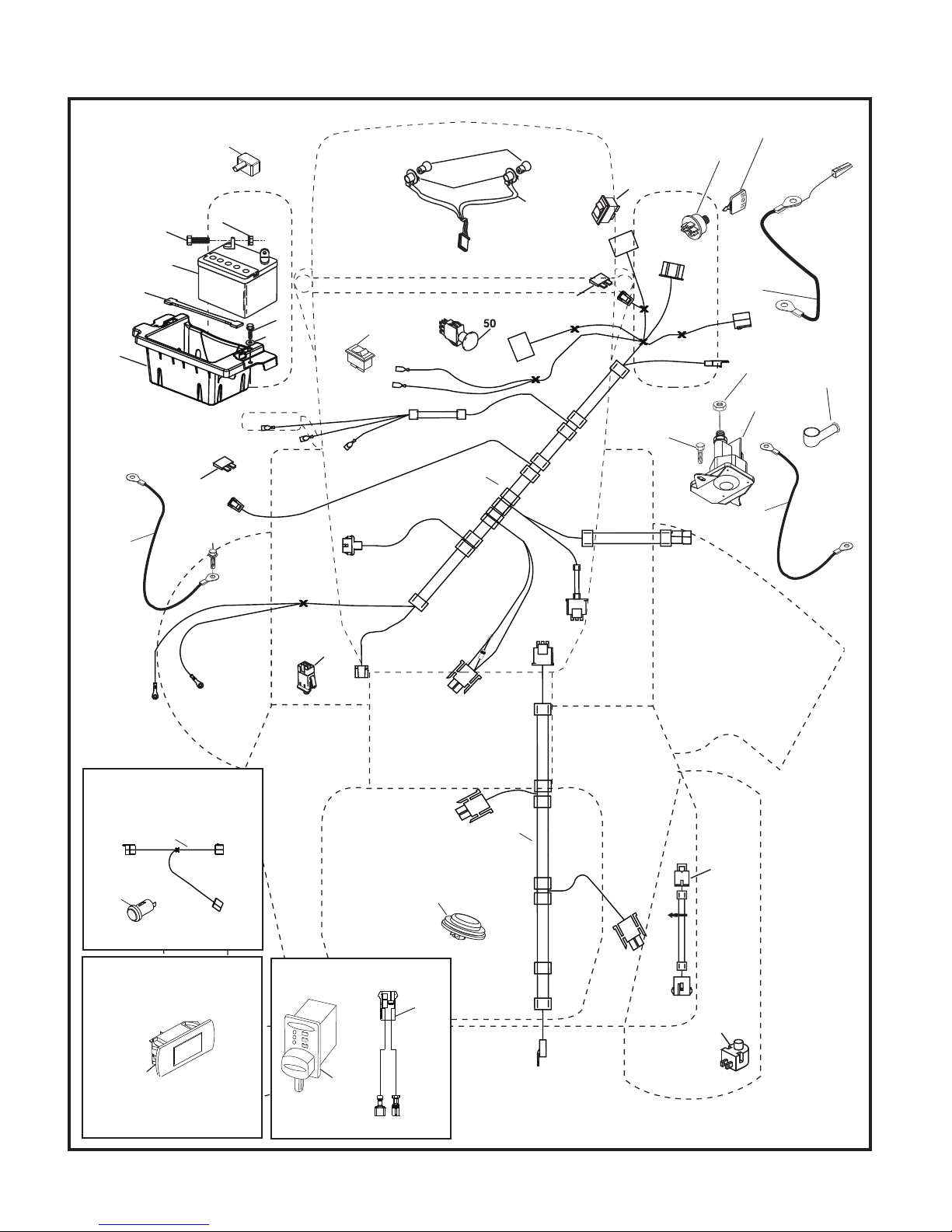
TRACTOR - MODEL NO. GTH3052TDF (96041028500), PRODUCT NO. 960 41 02-85
ELECTRICAL
T34S
90
79
26
55
27
99
100
34
2
1
91
8
28
22
75
21
26
41
40
30
24
27
33
42
43
25
With 12V Outlet Option
103
59
With Service Minder Option
46
16
71
102
29
With Charge Indicator Option
142
105
143
(+) (-)
4
Page 5

TRACTOR - MODEL NO. GTH3052TDF (96041028500), PRODUCT NO. 960 41 02-85
ELECTRICAL
KEY PART
NO. NO. DESCRIPTION
1 532 16 34-65 Battery
2 874 76 04-12 Bolt Hex Hd 1/4-20 unc x 3/4
8 532 18 64-91 Battery Box
16 532 17 61-38 Switch Interlock
21 532 40 02-52 Harness Socket Light
22 532 00 41-52 Bulb, Light #1156
24 532 40 02-53 Cable Battery
25 532 41 28-95 Cable Starter
26 532 17 51-58 Fuse
27 873 51 04-00 Nut Keps Hex 1/4-20 unc
28 532 14 54-91 Cable Ground 21” Blk 6 Ga.
29 532 40 15-45 Switch Seat
30 532 19 33-50 Switch Ign
33 532 41 19-33 Key/Chain
34 532 11 07-12 Switch Light/Reset
40 580 72 35-01 Harness Ign
41 817 72 04-08 Screw 1/4-20 unc x 1/2
42 532 13 15-63 Cover Terminal Red
43 532 19 25-07 Solenoid
46 532 40 17-63 Gauge Hourmeter
50 532 17 46-51 Switch PTO
55 817 06 05-12 Screw Thdrol 5/16-18 x 3/4
71 580 51 30-01 Harness Ign Chassis
75 580 36 64-01 Switch On/Off
79 532 17 52-42 Socket Asm. Bulb Twistlock
90 532 43 53-95 Cover Terminal Battery
91 532 19 02-70 Strap Battery
99 817 67 04-12 Screw Hexwsh Thdrol 1/4-20 x 3/4
100 819 09 14-16 Washer 9/32 x 7/8 x 16 Ga.
102 532 40 44-54 Harness Pigtail K46 Tex ROS
105 532 40 75-68 Switch Reverse
142 583 85 78-01 Harness Charge Port
143 532 44 80-59 Charge Port
NOTE: All component dimensions given in U.S. inches
1 inch = 25.4 mm
5
Page 6
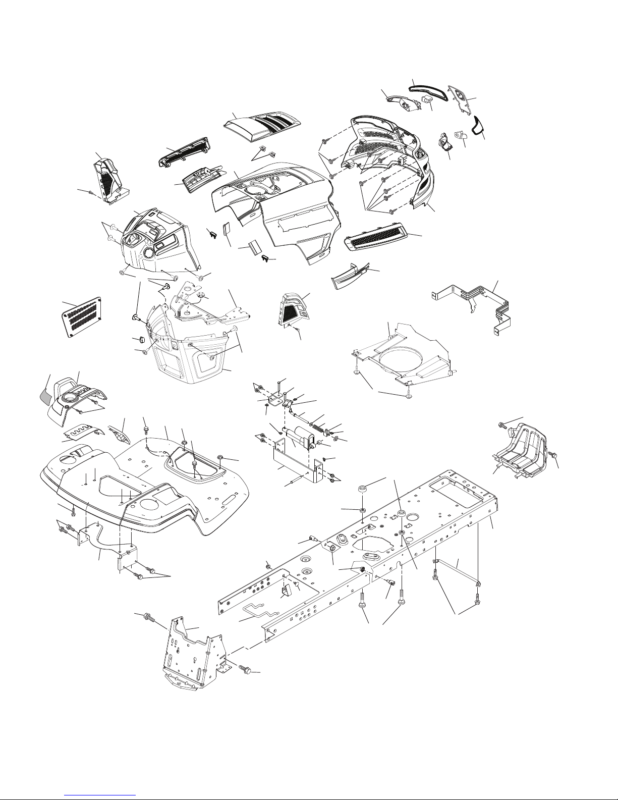
TRACTOR - MODEL NO. GTH3052TDF (96041028500), PRODUCT NO. 960 41 02-85
CHASSIS
221
199
162
189
178
350
196
336
176
162
195
176
161
205
150
235
15
297
202
18
207
191
3
25
151
159
152
159
208
204
203
214
14
206
5
137
234
36
176
175
177
176
182
361
354
353
361
194
360
362
176
36
37
194
137
351
359
352
350
130
353
356
335
355
19
357
236
365
130
130
130
358
353
179
353
361
58
189
159
2
chassis-tex_GT HUSQ_II_133_r2
165
306
159
125
228
146
180
217
194
228
183
236
68
6
Page 7

TRACTOR - MODEL NO. GTH3052TDF (96041028500), PRODUCT NO. 960 41 02-85
CHASSIS
KEY PART
NO. NO. DESCRIPTION
2 580 43 44-01 Drawbar
3 532 43 97-52 Logo Husq.
5 532 43 74-87 Dash
14 532 44 11-77 Hood
15 532 43 97-33 Lens LH
18 532 43 77-62 Grille Asm
19 819 13 13-12 Washer 13/32 x 13/16 x 12 Ga.
25 532 44 33-85 Lens RH
36 817 06 05-12 Screw 5/16-18 x 3/4
37 532 44 12-08 Fender
58 532 19 43-14 Bracket Fender
68 817 49 05-08 Screw 5/16-18 x 1/2
125 581 68 48-01 Clip Fuel Line
130 532 41 63-58 Screw #10 x 0.750 BOS Thread
137 532 40 75-90 Bumper Dash
146 581 85 79-01 Bolt
150 532 43 97-74 Duct Heat Hood
151 532 43 66-70 Bracket Pivot Hood
152 532 43 98-70 Shield Browning
159 817 00 06-12 Screw 3/8-16 x 3/4
161 532 43 99-29 Console Fuel Window
162 532 14 24-32 Screw Hex Wsh Hi-Lo 1/4 x 1/2
165 532 19 43-30 Bracket Support Tank
175 532 19 63-04 Crossmember
176 532 40 07-76 Screw 10-24 x 5/8 Wshd Qdrx
177 532 19 52-27 Bushing Steering
178 532 19 97-82 Cargo Asm. Net
179 532 16 89-37 Nut Push
180 532 44 55-59 Chassis
182 532 40 68-59 Dash Lower
183 874 52 05-20 Bolt 5/16-18 x 1-1/4
189 817 00 05-12 Screw 5/16-18 x 3/4
191 532 43 74-55 Insert Reflect. RH
194 873 90 05-00 Nut Lock Hex Flange 5/16-18
195 532 40 41-37 Plug
196 532 43 96-74 Console Asm. Deck Lift
199 532 19 82-59 Plate Deck Lift
202 532 43 97-28 Vent Side Hood RH
KEY PART
NO. NO. DESCRIPTION
203 532 43 97-27 Vent Side Hood LH
204 532 43 57-14 Vent Asm Hood Top
205 532 43 97-30 Skirt Hood Side RH
206 532 43 97-29 Skirt Hood Side LH
207 532 43 97-34 Bezel RH
208 532 43 97-35 Bezel LH
214 532 19 91-45 Clip Retainer
217 532 40 91-67 Rod Pivot
221 532 19 89-09 Reflector LH
228 532 19 51-61 Stud Fastener
234 532 40 47-42 Bumper Hood
235 532 40 61-29 Spacer Fender
236 873 93 05-00 Nut Center Lock 5/16-18 unc
297 532 43 74-56 Insert Reflect. LH
306 873 90 06-00 Nut Lock
335 532 44 82-04 Cover RH Lower
336 532 44 53-09 Cover LH Lower
350 532 44 51-43 Clip X-mas Tree
351 532 42 17-34 Pin Clevis .375 x 2.125
352 532 44 86-34 Clevis .375 x 2.125
353 532 17 80-62 Clip Retainer .0375
354 532 44 86-19 Support Bellcrank
355 532 44 86-36 Bellcrank Pivot Lock Diff
356 532 44 86-93 Link Lock Diff
357 532 44 86-84 Spring Compression
358 580 36 66-01 Swivel Guide
359 580 36 62-01 Actuator Electric
360 532 44 86-18 Bracket Actuator
361 817 49 06-10 Screw Hxwsh Thdr 3/8-16 x 5/8
362 532 44 86-33 Clevis .375 x 2.42
365 532 44 73-68 Nylon Spacer .375 x .4375L
- - 532 43 18-82 Kit Guard Brush
NOTE: All component dimensions given in U.S. inches
1 inch = 25.4 mm
7
Page 8
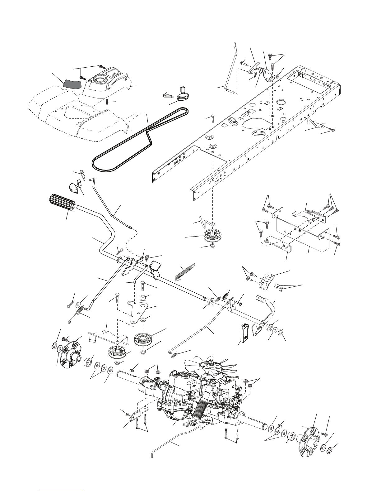
TRACTOR - MODEL NO. GTH3052TDF (96041028500), PRODUCT NO. 960 41 02-85
DRIVE
207
220
206
92
74
125
116
69
33
221
42
159
9
184
64
7
69
15
29
17
183
49
190
3
159
188
74
35
51
52
70
2
56
167
186
187
116
213
185
189
51
221
160
50
161
52
170
51
153
171
153
211
209
163
208
215
43
160
125
196
26
222
116
125
210
226
211
166
214
197
225
80
284
196
125
125
125
196
366
Drive-tex_K66_pedal_13
73
3
2
1
99
73
69
183
7
9
69
33
8
Page 9

TRACTOR - MODEL NO. GTH3052TDF (96041028500), PRODUCT NO. 960 41 02-85
DRIVE
KEY PART
NO. NO. DESCRIPTION
1 – – – – – – Transaxle, Tufftorq K66ELD
(580402201)(Order parts from
transaxle manufacturer.)
2 532 00 70-70 Key 1/4 x 2.5
3 532 00 75-63 Washer Thrust Axle Hardened
7 532 19 98-37 Hub Asm. Wheel
9 532 14 00-80 Bolt Hub Wheel
15 819 13 13-16 Washer 13/32 x 13/16 x 16 Ga.
17 532 40 10-72 Spring, Brake
26 532 19 96-79 Spring Return Cruise
29 532 40 72-45 Rod, Brake
33 812 00 00-53 Ring E
35 583 86 45-01 Rod, Brake, Park
42 532 12 48-72 Cover, Foot Pedal
43 874 18 04-12 Screw Mach. CR. 1/4-20 x 3/4
49 872 11 06-14 Bolt
50 532 19 43-27 Pulley Idler Flat
51 873 90 06-00 Lock Nut 3/8-16
52 532 19 43-26 Idler V-Groove
56 532 12 59-07 V-Belt, Drive
64 532 19 78-65 Shaft Asm. Pedal Brake Control
69 532 12 38-00 Washer 1-1/32 x 1-5/8 x 16 Ga.
70 532 43 96-61 Console Asm
73 874 49 05-48 Bolt Hex Flghd 5/16-18 Gr. 5
74 532 14 24-32 Screw 1/4 x 1/2
80 532 40 71-82 Strap Torque
92 874 76 05-20 Bolt 5/16-18 x 1/2
99 532 41 57-44 Spring Bypass
116 873 90 05-00 Nut Lock Hex Flange 5/16-18
125 817 00 05-12 Screw 5/16-18 x 3/4
153 532 12 47-88 Retainer Spring
159 876 02 04-12 Pin Cotter 1/8 x 3/4
160 532 16 94-84 Retainer Clip
161 532 10 57-09 Spring, Return, Clutch
163 532 40 72-46 Rod Pedal Control
KEY PART
NO. NO. DESCRIPTION
166 532 42 91-64 Nut Push .625
167 532 40 52-57 Latch Brake Parking
170 532 19 43-22 Keeper V-Idler Centerspan
171 872 11 06-16 Bolt Rd Hd Sq NK 3/8-16 unc x 2
183 532 19 73-57 Spacer Axle
184 532 44 14-55 Handle Parking Brake
185 872 11 06-22 Bolt Rdhd 3/8-16 unc x 2-3/4 G5
186 532 19 43-21 Spacer Retainer
187 819 13 32-10 Washer
188 532 19 43-23 Link Clutch Ground Drive
189 532 19 43-17 Bellcrank Ground Drive
190 532 19 43-18 Keeper Bellcrank Ground Drive
196 817 00 06-16 Screw 3/8-16 x 1
197 532 19 97-69 Bracket Clutch Anti-Rotation
206 532 19 78-67 Bracket Mount Latch Cruise
207 532 19 78-68 Latch Control Cruise
208 532 19 78-69 Gear Sector Control Cruise
209 532 19 95-92 Rod Control Cruise
210 532 19 78-60 Rocker Asm. Pedal Control
211 532 12 01-83 Bearing Nylon
213 532 40 31-19 Knob Control Cruise
214 532 41 68-63 Pedal Forward
215 532 41 94-82 Pedal Reverse
220 532 19 89-08 Reflector RH
221 532 40 31-87 Retainer Spring Clip Handle
222 879 21 20-10 Washer 21/32 x 1-1/4 x 10 Ga.
225 532 40 73-11 Keeper Belt
226 532 40 71-09 Bracket Mount Torque
284 532 41 76-93 Nut U-Chnl. 1/4-20
366 580 62 62-01 Bracket Reinforcement
NOTE: All component dimensions given in U.S. inches
1 inch = 25.4 mm
9
Page 10
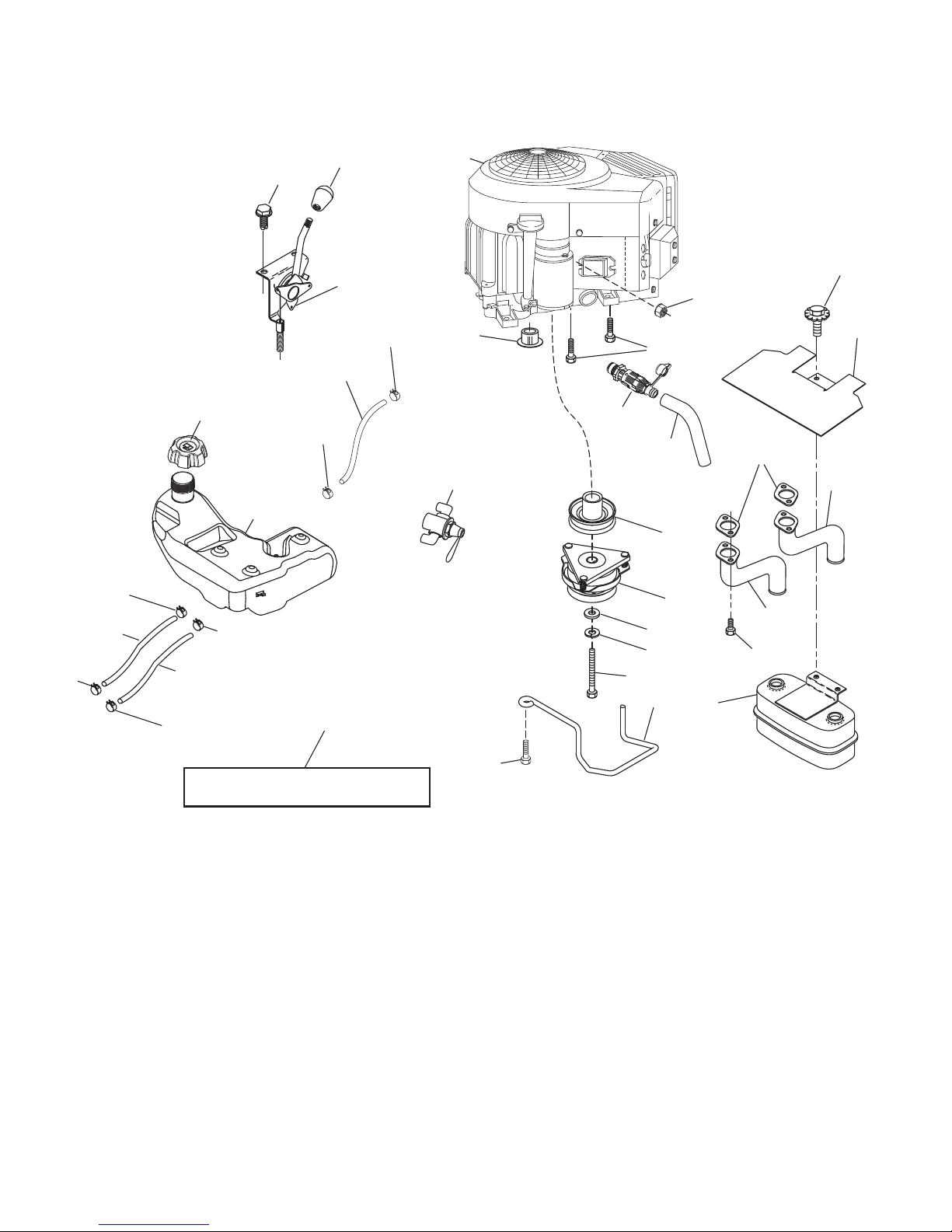
TRACTOR - MODEL NO. GTH3052TDF (96041028500), PRODUCT NO. 960 41 02-85
ENGINE
37
28
37
37
28
18
37
15
21
37
29
116
20
28
37
117
1
91
82
85
84
41
42
9
81
12
87
45
62
69
71
11
70
79
2
SPARK ARRESTER KIT
engine-tex_bs-2cyl_79
90
10
Page 11

TRACTOR - MODEL NO. GTH3052TDF (96041028500), PRODUCT NO. 960 41 02-85
ENGINE
KEY PART
NO. NO. DESCRIPTION
1 – – – – – – Engine B&S Model No. 49M877-
5598-G5 (448325)(Order parts
from engine manufacturer.)
2 532 14 97-23 Muffler
9 532 19 43-20 Keeper Asm. Belt Engine
11 532 17 93-35 Clutch Electric
12 532 19 43-43 Pulley Engine
15 532 42 28-04 Tank Fuel
18 532 43 96-45 Cap Asm
20 532 42 43-40 Control Throttle
21 532 41 63-58 Screw #10 x 0.750 BOS Thread
28 532 14 21-58 Fuel Line
29 532 13 71-80 Spark Arrester Kit
37 532 12 34-87 Clamp Hose
41 532 12 61-97 Washer 1-1/2 OD x 15/32 ID x .250
42 810 04 07-00 Washer Lock 7/16
45 873 51 04-00 Nut Keps Hex 1/4-20 unc
62 532 43 40-17 Shield Heat Muffler
69 532 16 53-91 Gasket
70 532 15 99-55 Tube Exhaust LH
71 532 16 05-89 Tube Exhaust RH
79 532 18 39-06 Screw Socket HD 5/16-18 x 1
81 532 14 84-56 Tube Drain Oil
82 532 42 82-87 Valve Oil Drain
84 817 06 06-20 Screw 3/8-16 x 1-1/4
85 532 17 99-53 Bolt 7/16-20 x 3.75 Gr. 5
87 532 19 82-39 Bolt 5/16-18 unc x 1 w/Sems
90 817 00 06-16 Screw 3/8-16 x 1
91 532 18 74-95 Bushing
116 539 13 26-24 Knob Shift
117 532 42 08-28 Valve Fuel Reserve
NOTE: All component dimensions given in U.S. inches
1 inch = 25.4 mm
Engine Power Rating Information
The gross power rating for individual gas engine models is labeled in accordance with SAE (Society of Automotive Engineers) code J1940 (Small Engine Power & Torque Rating Procedure), and rating performance has been obtained and
corrected in accordance with SAE J1995 (Revision 2002-05). Torque values are derived at 3060 RPM; horsepower values
are derived at 3600 RPM. Actual gross engine power will be lower and is affected by, among other things, ambient operating conditions and engine-to-engine variability. Given both the wide array of products on which engines are placed and
the variety of environmental issues applicable to operating the equipment, the gas engine will not develop the rated gross
power when used in a given piece of power equipment (actual “on-site” or net power). This difference is due to a variety
of factors including, but not limited to, accessories (air cleaner, exhaust, charging, cooling, carburetor, fuel pump, etc.),
application limitations, ambient operating conditions (temperature, humidity, altitude), and engine-to-engine variability.
Due to manufacturing and capacity limitations, Briggs & Stratton may substitute an engine of higher rated power for this
Series engine.
11
Page 12
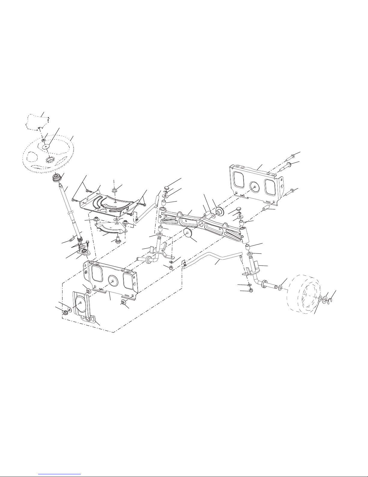
TRACTOR - MODEL NO. GTH3052TDF (96041028500), PRODUCT NO. 960 41 02-85
STEERING ASSEMBLY
26
45
51
64
13
21
16
28
1
22
122
50
63
19
35
58
60
59
122
4
63
54
13
54
66
53
8
65
9
8
118
118
14
7
78
67
55
2
9
8
7
67
62
14
15
118
55
118
6
5
61
6
15
69
68
Steering-tex_LEGND2_38_r2
65
70
50
13
12
Page 13

TRACTOR - MODEL NO. GTH3052TDF (96041028500), PRODUCT NO. 960 41 02-85
STEERING ASSEMBLY
KEY PART
NO. NO. DESCRIPTION
1 532 43 97-40 Wheel, Steering
2 532 41 35-91 Axle Asm., Front
4 532 40 30-89 Spindle Asm., LH
5 532 40 30-90 Spindle Asm., RH
6 532 12 49-31 Bearing, Race Thrust Harden
7 532 12 17-48 Washer 25/32 x 1-5/8 x 16 Ga.
8 812 00 00-29 Ring, Klip #T5304-75
9 532 12 12-32 Cap, Spindle
13 532 12 17-49 Washer 25/32 x 1-1/4 x 16 Ga.
14 810 04 06-00 Washer, Lock Hvy Hlcl Spr 3/8
15 873 54 06-00 Nut, Crown Lock 3/8-24 unf
16 532 19 47-46 Shaft Steering
19 532 19 47-29 Plate Steering
21 532 18 67-37 Adapter, Wheel Steering
22 532 42 05-37 Strg. Supt. Lower
26 532 43 97-43 Insert, Wheel Steering
28 817 00 06-12 Screw 3/8-16 x 3/4
35 532 19 47-32 Gear, Sector Plate
45 819 18 38-12 Washer 9/16 x 2-3/8 x 12 Ga.
50 873 90 06-00 Nut Lock Flg. 3/8-16 unc
51 873 94 08-00 Nut Hex Jam Toplock 1/2-20 unf
53 532 18 89-67 Washer Hardened .793 x 1.637 x .060
54 874 76 06-36 Bolt Hex Hs 3/8-16 unc x 2-1/4
55 532 41 47-36 Spacer Brace Axle
58 532 19 47-47 Bolt Shoulder Sector Pivot CFM
59 532 19 47-48 Washer Thrust Sector Steering
60 873 97 10-00 Nut Flange Lock 5/8-11
61 532 19 47-40 Draglink, LH
62 532 19 47-41 Draglink, RH
63 817 00 05-12 Screw 5/16-18 x 3/4
64 532 19 98-49 Retainer Clip Spring Steering
65 532 19 47-34 Brace Axle Front
66 871 02 07-48 Bolt Hex Fghd 7/16-14 x 3 Serr
67 532 19 47-37 Bushing PM Front Axle
68 873 90 07-00 Nut Lock Flange 7/16-14 Gr. 5
69 532 19 91-62 Washer 1.5 x .505 x .118
70 532 19 61-97 Bracket Deck Susp. Front
78 532 05 70-79 Washing Thrust
118 532 40 60-13 Bushing
122 532 44 49-62 Cap Gear Sector
NOTE: All component dimensions given in U.S. inches
1 inch = 25.4 mm
13
Page 14
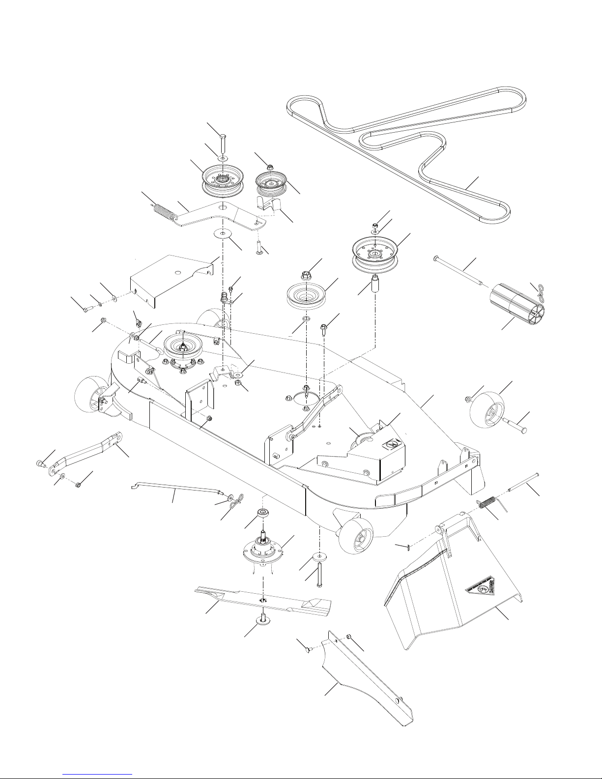
TRACTOR - MODEL NO. GTH3052TDF (96041028500), PRODUCT NO. 960 41 02-85
MOWER DECK
52
37
45
46
16
39
43
15
43
27
36
57
56
55
18
17
33
16
25
34
51
50
24
35
33
32
53
19
31
54
5
4
21
6
3
59
30
44
20
41
42
40
22
24
1
23
38
61
10
52F-tex_elec_6_r1
62
42
58
11
2
29
13
14
9
8
60
28
7
14
12
Page 15

TRACTOR - MODEL NO. GTH3052TDF (96041028500), PRODUCT NO. 960 41 02-85
MOWER DECK
KEY PART
NO. NO. DESCRIPTION
1 575 43 80-03 Deck Asm. 52"
2 539 11 21-70 Housing Assembly
3 532 18 76-90 Washer-Spacer
4 532 17 43-75 Pulley, Mandrel
5 532 40 02-34 Nut Flange Lock Top
6 532 17 39-84 Screw Thd Roll
7 539 11 07-33 Discharge Chute, 52"
8 539 11 07-35 Spring - Torsion
9 539 11 07-36 Pin, Clevis 5/16 x 5.19
10 574 87 08-01 Blade, 16-1/4"
11 532 19 30-03 Bolt, Washer Asm. 7/16-20 unf
12 574 87 50-01 Confinement Plate
13 872 11 05-05 Bolt Carr 5/16-18 x 5/8
14 873 80 05-00 Nut Lock 5/16-18 unc
15 532 19 51-61 Stud, Fasten w/ Anti- Rotate
16 539 11 28-99 Nut 5/16-18 Hex Flange Nyloc
17 532 19 61-04 Pulley, Idler Spec. Hub
18 574 84 18-01 Arm, Idler, Blk
19 532 17 79-68 Pulley, Idler
20 539 13 27-28 Pulley, Idler
21 575 22 45-01 Idler Bushing
22 532 13 39-57 Wheel, Gauge
23 532 19 34-06 Bolt, Shoulder
24 521 99 65-01 Nut 3/8-16 Hex Flg Nyloc
25 575 22 47-02 Shield, Belt LH
27 539 10 47-63 Retainer 5/16-18 U Type
28 539 10 82-71 Hcs 3/8-16 x 3-1/2 Gr 5
29 539 10 65-04 Heavy Washer
30 819 14 16-14 Washer, 3/8 Flat
31 539 97 69-79 Nut 3/8-16 Hex Nyloc
32 539 99 09-23 Rhsnb 3/8-16 x 1-3/4 Gr 5
33 539 10 48-64 Washer, 7/16 Flat
34 532 17 85-15 Washer, Flat Hardened
KEY PART
NO. NO. DESCRIPTION
35 873 90 07-00 Nut, 7/16-14 Gr. 5
36 532 19 51-85 Arm, Susp., Rear
37 539 11 36-21 Sb 3/8-16 x 3/8 Skt Hd
38 819 13 13-16 Washer, 13/32 x 13/16 x 16 Ga.
39 539 20 02-82 Nut, 3/8-16 Hex Jam Nyloc
40 532 17 60-66 Roller, Nose
41 532 17 91-27 Rod, Roller, Nose, Narrow
42 532 19 42-08 Pin Cotter 5/16 Bow Tie Lock
43 819 12 14-14 Washer, 3/8 x 7/8 x 14 Ga.
44 575 96 73-02 Shield, Belt RH
45 874 78 05-16 Bolt Fin Hex 5/16-18 unc x 1.00
46 810 03 05-00 Washer 5/16
50 532 41 55-98 Washout Port
51 817 49 04-08 Bolt, 1/4-20 x 1/2
52 874 78 07-40 Bolt 7/16-14 x 2-1/2
53 574 84 56-03 Belt, Deck
54 532 14 10-43 Guard, Idler
55 539 11 55-74 Eyebolt 5/16 x 3-1/2
56 539 99 05-85 Nut 5/16-18 Hex Whizlk
57 539 10 68-50 Spring
58 532 11 04-85 Ball Bearing
59 575 35 29-01 Pulley
60 532 16 94-84 Clip Retainer
61 532 40 03-37 Rod Anti-Sway
62 819 13 13-12 Washer 13/32 x 13/16 x 12 Ga.
- - 532 44 53-61 Mower Deck Complete
NOTE: All component dimensions given in U.S. inches
1 inch = 25.4 mm
15
Page 16
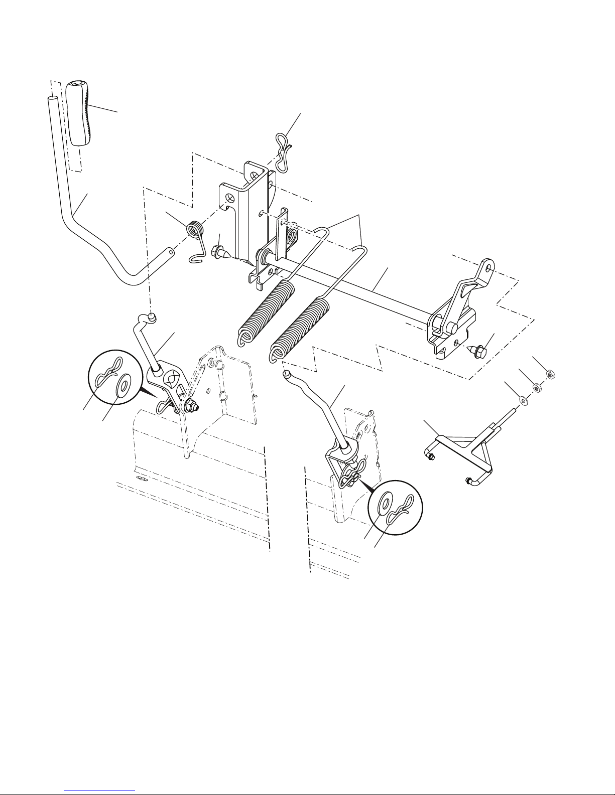
TRACTOR - MODEL NO. GTH3052TDF (96041028500), PRODUCT NO. 960 41 02-85
MOWER LIFT
LIFTTEX?
KEY PART
NO. NO. DESCRIPTION
2 532 42 20-27 Shaft Asm., Lift
3 532 19 52-30 Lever Asm., Lift RH
7 532 41 15-55 Grip, Lever
10 532 19 63-14 Spring Torsion
41 532 17 59-94 Nut Lift Link
87 532 19 42-09 Pin Cotter 7/16 Bow Tie Lock
88 532 19 53-04 Spring Lift Assist
89 819 19 19-12 Washer Clear Zinc
KEY PART
NO. NO. DESCRIPTION
91 532 40 34-07 Link Lift Susp Mower Rear
96 532 19 52-63 Bushing Spherical
97 817 00 06-12 Screw 3/8-16 x .75
98 574 82 25-01 Weldment Front Deck Suspension
114 873 36 07-00 Nut Jam 7/16-20
NOTE: All component dimensions given in U.S. inches
1 inch = 25.4 mm
16
Page 17
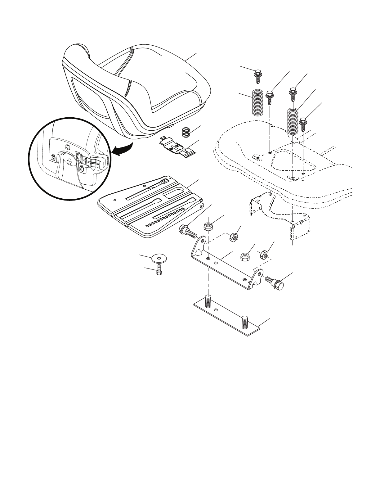
TRACTOR - MODEL NO. GTH3052TDF (96041028500), PRODUCT NO. 960 41 02-85
SEAT ASSEMBLY
1
44
41
40
10
21
8
8
8
7
7
8
6
37
6
2
37
43
seat-tex_6.5SL_3
KEY PART
NO. NO. DESCRIPTION
1 532 44 32-63 Seat
2 532 18 01-66 Bracket Pivot Fender
3 532 14 06-75 Strap, Asm Fender
6 873 80 06-00 Nut, Lock w/Ins. 3/8-16 unc
7 532 12 41-81 Spring, Seat Cprsn
8 532 17 18-77 Bolt 5/16-18 unc x 3/4 w/Sems
10 532 19 69-77 Pan, Seat
21 532 17 18-52 Bolt, Shoulder 5/16-18
21
3
KEY PART
NO. NO. DESCRIPTION
37 873 80 05-00 Nut, Lock 5/16-18 unc
40 532 19 76-61 Handle Slide Seat
41 532 19 82-00 Spring Latch Seat
43 874 76 06-12 Bolt Fin Hex 3/8-16 unc x 3/4
44 819 13 38-12 Washer 13/32 x 2-3/8 x 12 Ga.
NOTE: All component dimensions given in U.S. inches
1 inch = 25.4 mm
17
Page 18
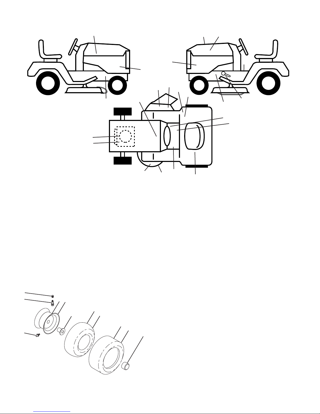
TRACTOR - MODEL NO. GTH3052TDF (96041028500), PRODUCT NO. 960 41 02-85
6
2
1
3
11
4
10
5
9
8
7
wheel_art_1-vgt
DECALS
16
17
16
2
6
7
KEY PART
NO. NO. DESCRIPTION
1 532 40 03-89 Decal, Operator’s
2 532 15 97-36 Decal, Hot Muffler
3 532 15 97-37 Decal, Brake Clutch
4 532 12 44-33 Decal, 80 DBA
5 532 42 62-09 Decal, Warning Reserve
6 532 44 47-73 Decal, Eng. H.P.
7 532 19 68-41 Decal, Warning Eng. Sym.
8 532 14 08-37 Decal, Brake Parking
9 532 14 50-05 Decal, Battery Dnge/Poi
10 532 17 83-02 Decal, Oper. Cruise Sym.
11 532 16 88-69 Decal, Tick Mark
12 532 41 86-00 Decal, Pedal
14
14
15
13
9
13
18
4
11
2
8
3
5
1
12
10
KEY PART
NO. NO. DESCRIPTION
13 581 72 43-01 Decal, No Step
14 580 78 94-01 Decal, Panel Side
15 539 11 32-24 Decal, Warning
16 581 62 73-01 Decal, Hood Logo
17 532 44 25-91 Decal, Replacement
18 532 19 87-85 Decal, Mower Sch.
- - 532 16 25-98 Decal, Load Limit
- - 532 16 69-60 Decal, Bypass
- - 532 43 98-82 Pad, Footrest, LH
- - 532 43 98-81 Pad, Footrest, RH
- - 580 65 81-30 Manual, Operator's (Eng)
WHEELS AND TIRES
KEY PART
NO. NO. DESCRIPTION
1 532 05 91-92 Cap, Valve, Tire
2 532 06 51-39 Stem, Valve
3 532 44 42-85 Rim Assembly, Front
4 532 00 81-34 Tube, Front (Service Item Only)
5 532 10 62-30 Tire, Front
6 532 12 49-57 Fitting, Grease (Front Wheel Only)
7 532 12 49-59 Bearing, Flange (Front Wheel Only)
8 532 17 50-39 Cap, Axle
9 532 10 55-88 Tire, Rear
10 532 00 71-54 Tube, Rear (Service Item Only)
11 532 14 45-10 Rim Assembly, Rear
- - 532 14 43-34 Sealant, Tire (10 oz. Tube)
NOTE: All component dimensions given in U.S. inches
1 inch = 25.4 mm
18
Page 19

Consumer Wheeled Products - Limited Warranty
Husqvarna warrants to the original retail purchaser that this product is free from defects in material or workmanship under normal use
and maintenance from the date of retail purchase for the applicable Warranty Period shown on Exhibit A. This Limited Warranty may not be transferred
to any subsequent purchaser of this product. Certain components (e.g., engines and transmissions) are excluded from coverage, and other
limitations apply, as described in this document. Husqvarna will repair or replace at its discretion, any defective product or part covered by the Limited
Warranty, free of charge at any authorized Husqvarna Servicing Dealer/Center using original OEM Husqvarna replacement parts, subject to the
limitations and exclusions described below. Husqvarna does not offer an over-the-counter exchange program.
DISCLAIMERS, LIMITATIONS AND EXCLUSIONS
1. WARRANTY DISCLAIMER. THIS LIMITED WARRANTY IS THE SOLE EXPRESS WARRANTY PROVIDED BY HUSQVARNA AND THERE ARE NO
WARRANTIES WHICH EXTEND BEYOND THE DESCRIPTION ON THE FACE HEREOF, EXCEPT AS MAY BE PROVIDED BY LAW. THIS WARRANTY IS
GIVEN ONLY BY HUSQVARNA, AND MAY BE MODIFIED ONLY BY HUSQVARNA. THIS LIMITED WARRANTY IS THE FINAL EXPRESSION OF OUR
AGREEMENT, AND IS A COMPLETE AND EXCLUSIVE STATEMENT OF THE TERMS OF THAT AGREEMENT. THIS LIMITED WARRANTY GIVES YOU
SPECIFIC LEGAL RIGHTS, AND YOU MAY ALSO HAVE OTHER RIGHTS WHICH VARY BASED ON LOCALITY
2. LIMITED DURATION. ANY WARRANTY THAT MAY BE IMPLIED BY LAW (INCLUDING ANY IMPLIED WARRANTY OF FITNESS FOR A
PARTICULAR PURPOSE OR USE AND IMPLIED WARRANTY OF MERCHANTABILITY) IS LIMITED TO THE DURATION OF THE APPLICABLE
WARRANTY PERIOD UNDER THIS LIMITED WARRANTY. SOME LOCALITIES DO NOT ALLOW LIMITATIONS ON HOW LONG AN IMPLIED
WARRANTY LASTS, SO THE ABOVE LIMITATIONS MAY NOT APPLY TO YOU.
3. EXCLUSIVE REMEDIES. SOME LOCALITIES, INCLUDING THE PROVINCE OF QUEBEC, DO NOT ALLOW THE EXCLUSION OR LIMITATION OF
LIABILITY FOR INJURY TO PERSON OR FOR DAMAGES RESULTING FROM THE FAULT OF THE MANUFACTURER AND/OR THE EXCLUSION OR
LIMITATION OF INCIDENTAL OR CONSEQUENTIAL DAMAGES. AS SUCH, SOME OF THE FOLLOWING LIMITATIONS MAY NOT APPLY TO YOU. THE
ABOVE REMEDIES ARE THE EXCLUSIVE REMEDIES FOR ANY BREACH OF THIS LIMITED WARRANTY. NO OTHER REMEDY, INCLUDING, BUT NOT
LIMITED TO ANY SPECIAL, INCIDENTAL, INDIRECT OR CONSEQUENTIAL DAMAGES, FOR LOST PROFITS, LOST SALES, INJURY TO PERSON OR
PROPERTY, OR ANY OTHER INCIDENTAL OR CONSEQUENTIAL LOSS SHALL BE AVAILABLE, AND ALL SUCH DAMAGES ARE HEREBY
DISCLAIMED.
4. Engines, Transmissions and certain other components are NOT covered. This Limited Warranty does not cover any of the following:
(a) Engines and Attachments.Except where otherwise indicated on Exhibit A, all Engines and Attachments are not covered by this Limited Warranty. In most cases, these
items are NOT manufactured by Husqvarna in which case they may be covered separately by their respective manufacturer's warranties if one is provided and included with
the product at the time of purchase. All such claims must be submitted and sent to the appropriate manufacturer or as otherwise directed in those separate warranties.
Husqvarna is not authorized to handle warranty adjustments or repairs on engines manufactured by Briggs & Stratton, Honda, Kawasaki, or Kohler (with the exception of
models equipped with LCT engines). Husqvarna does not assume any warranty obligation of the other manufacturers' engines under this Limited Warranty.
(b) Transmissions. Except where otherwise indicated on ExhibitA, Transmission / Transaxle (including Drive Systems) are not covered by this Limited Warranty. In most
cases, these items are NOT manufactured by Husqvarna in which case they may be covered separately by their respective manufacturer's warranties if one is provided and
included with the product at the time of purchase. The following transmission / transaxle manufacturers, Dana, Hydro-Gear, Tuff-Torq provide a warranty for the
transmission / transaxle to the ultimate purchaser or to Husqvarna. Husqvarna will assign the transmission / transaxle manufacturer's warranty or any rights thereof to the
original purchaser of the unit. To obtain transmission / transaxle warranty service, first contact the retailer who you purchased the unit from. Should you require assistance
or have any questions concerning transmission / transaxle warranty coverage, contact Husqvarna directly at our website www.husqvarna.com or call 800-487-5951 (US) or
800-805-5523 (Canada) for an authorized Husqvarna service provider. All such claims must be submitted and sent to the appropriate manufacturer or as otherwise directed
in those separate warranties. Husqvarna is not authorized to handle warranty adjustments or repairs on transmissions or transaxles. Husqvarna does not assume any
obligations under this Limited Warranty for the above listed manufacturers (for exceptions - see Exhibit A).
(c) Expendable Parts. This Limited Warranty does not cover general maintenance parts and items ("Expendable Parts"), including without limitation spark plugs, bulbs,
filters, lubricants, starter cords, belts, blades, and blade adapters.
(d) Emissions Control Components. This Limited Warranty does not cover Emissions control equipment and components to the extent regulated by the U.S. Environmental
Protection Agency or similar state, provincial or federal agencies. Such equipment and components are covered by a separate emission control warranty statement supplied
with your new product. Please consult this separate warranty statement for details.
5. Any COMMERCIAL, INSTITUTIONAL, AGRICULTURAL, INDUSTRIAL, INCOME PRODUCING, or RENTAL use will result in either
No Warranty or a Shortened Warranty Period. Depending on the product, there is either NO WARRANTY (whether statutory, contractual or
otherwise) or a reduced warranty if the product is used for commercial, institutional, agricultural, industrial, income producing, or rental purposes and, in
such circumstances, this Limited Warranty is offered instead of and replaces any warranty regime provided for by law. Please refer to Exhibit A.
6. Reconditioned or Refurbished Products have a 30 Day Limited Warranty. Under this Limited Warranty, Certified Factory Reconditioned or
Refurbished products have a 30 Day Limited Warranty for parts and labor for Non-Commercial Use. Products are only reconditioned at the Husqvarna
Factory.
7. Owner's (Your) Responsibilities. To preserve your rights under this Limited Warranty, you must exercise reasonable care and use of the product,
including, following the preventative maintenance, storage, fuel and oil usages as prescribed in the enclosed operator's manual. For example, the
following items are the Owner's responsibility and are not covered by this Limited Warranty:
a. Set-up and pre-delivery service, and engine tune-ups;
b. Adjustments after the first (30) thirty days of purchase and beyond, such as throttle cable, belt guides adjustments; and
c. Preventative maintenance as outlined in the operator's manual.
In addition, you must cease using the product immediately upon any failure or damage. The product should be taken to an authorized Husqvarna
servicing dealer prior to any further use.
8. Damages resulting from normal aging, wear and tear or neglect are NOT covered. The Limited Warranty does not cover damage other than
that resulting from defects in material or workmanship. The following are NOT considered defects in material or workmanship, and therefore are NOT
covered.
19
Page 20

(a)Ab
rasionto mower decks;
(b) Tires damaged by external punctures;
(c) Natural discoloration of materials due to ultraviolet light;
(d) Damage to cutting equipment by way of contact with, rocks, or other non-approved materials and/or structures;
In addition, this Limited Warranty does not cover damages, malfunctions or failures resulting from abuse or neglect of the product related to or including
any of the following:
(e) Failure to provide or perform required maintenance services as prescribed in the operator's manual;
(f) Abuse, misuse, neglect, modifications, alterations, normal wear, improper servicing, use of unauthorized attachments, Lack of lubrication or
engine failure, due to the use of oils that do not meet Engine manufacturer's specifications;
(g) Use of gasohol, containing methanol (wood alcohol). Gasohol which contains a maximum 10% ethanol (grain alcohol) or 15% MTBE
(methyl/tertiary/butyl/ether) is approved;
(h) Use of ether or any starting fluids;
(i) Pressure cleaning or steam cleaning the product;
(j) Use of spark plugs other than those meeting emission performance requirements listed in the operator's manual;
(k) Tampering with engine speed governor or emission components, or running engines above specified and recommended engine speeds as
listed in your operator's manual;
(l) Operation of the unit with improperly installed/removed or modified cutting shields, guards, or safety devices;
(m) Any removed/damaged air filter, excessive dirt, abrasives, salt water, moisture, corrosion, rust, varnish, stale fuel, or any adverse reaction due
to incorrect storage procedures;
(n) Failures due to improper set up, pre-delivery service or repair service by anyone other than an authorized Husqvarna servicing dealer during
the warranty period;
(o) Dirt contaminated grease or oil, use of incorrect type of greases or oils, failure to comply with recommended greasing intervals, water or
moisture damage, and/or improper storage;
(p) Sprayers pumping or sprayin g caustic or flammable materials, lack of or broken strainers; or
(q) Continued use of product, after initial operational problem or failure occurs.
9. Reinforced Stamped (Armor Protected) 10 Year Limited & Fabricated Limited Lifetime, Deck Warranties. These Limited Warranties are for
the deck shell only
wheels
workmanship. The following are NOT considered defects in material or workmanship, and therefore are NOT covered:
(a) Abrasion to mower decks, including sand wear;
(b) Damage to cutting equipment by way of contact with, rocks, or other non-approved materials and/or structures;
(c) Rust and corrosion; and
(d) Natural discoloration of paint or other materials due to ultraviolet light.
10. Authorized Husqvarna Servicing Dealer/Center. In order to obtain warranty coverage it is your responsibility (at your expense) to deliver or ship
your Husqvarna unit to an authorized Husqvarna Servicing Dealer/Center and arrange for pick-up or return of your unit after the repairs have been made.
If you do not know the location of your nearest authorized Husqvarna Servicing Dealer, call Husqvarna, at 1-800-487-5951 during the hours of 8:00 AM
to 8:00 PM Eastern Standard Time, or visit www.husqvarna.com. Should you require assistance or have questions concerning this Limited Warranty, you
may contact us at 800-487-5951 (US) or 800-805-5523 (Canada) during the hours of 8:00 AM to 8:00 PM Eastern Standard Time or contact us through
the web at www.husqvarna.com.
11. Documentation Required. You must maintain and present Proof of purchase (including date, product model and, if applicable, engine serial
number) to an authorized Husqvarna Servicing Dealer for warranty service under this Limited Warranty. Proof of purchase rests solely with you.
Husqvarna encourages you to register your product online at www.usa.husqvarna.com (US & Canada) to help ensure, among other things, that you can
be notified of important product information. However, registering your product is not a condition of warranty service.
mechanical components/parts such as belts, pulleys, spindle housings, bearings, blades, rods, height adjusters, caster/anti scalp
are NOT covered. The Limited Lifetime Warranty does not cover damage other than that resulting from defects in material or
HOW TO OBTAIN SERVICE
Husqvarna Professional Products, NA, Inc.
9335 Harris Corners Parkway, Suite 500, Charlotte, NC28269
575 49 43-01 W 2012 IR
20
Page 21
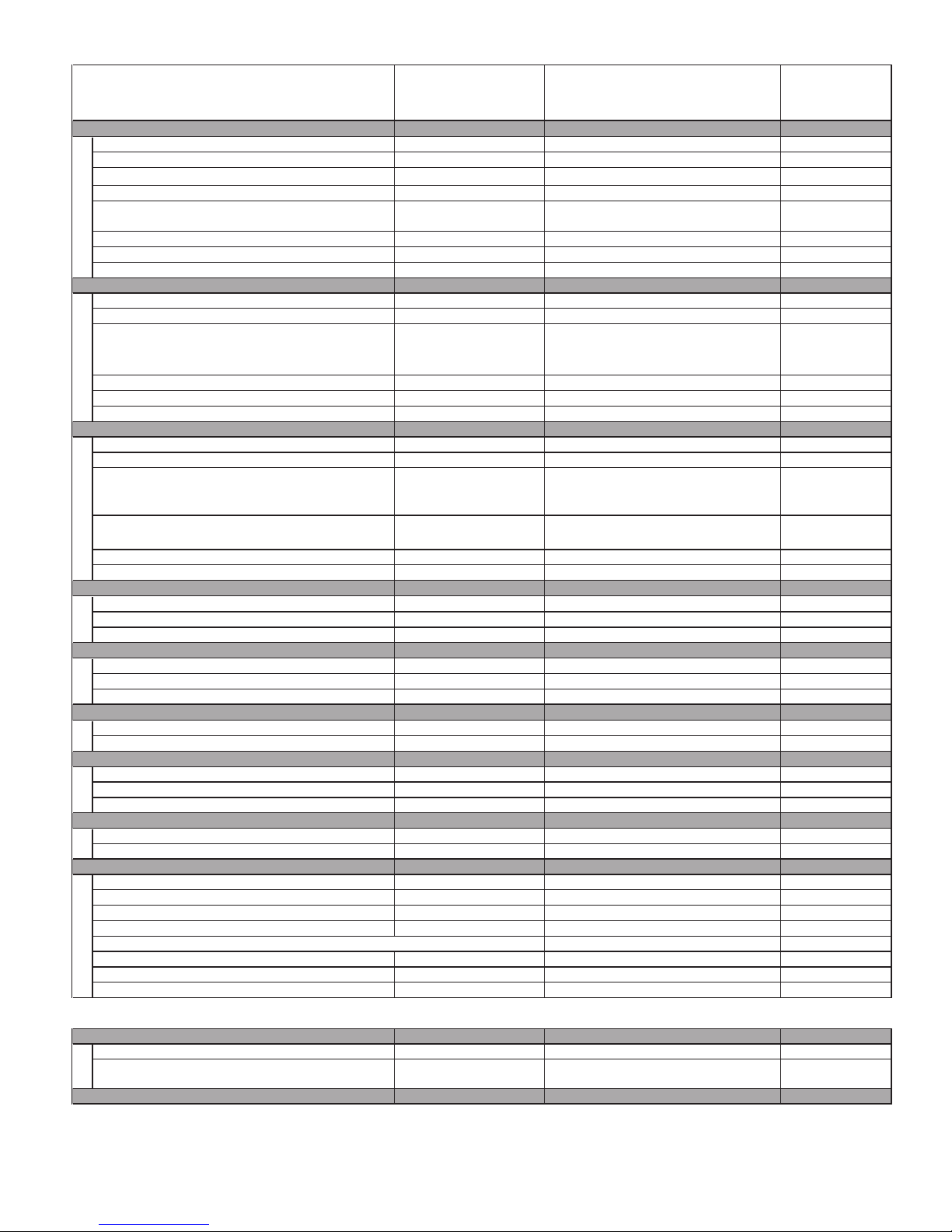
Consumer Wheeled Limited Warranty Chart 2012 Exhibit A
)
y
y
y
y
y
y
y
y
y
y
y
y
y
y
y
y
y
y
y
p
Consumer (personal,
household use only)
Product/Com
Riding Lawn Tractors:
Frame, Chassis, Front Axle 5 Years No Warranty No Warranty
Engine*
Transmission (if made by Husqvarna/Peerless)
Transmission (if third party)** ** ** **
XLS Models only - stamped deck shell. Armor
Protected Limited Warranty
Fabricated Deck shell. Limited Lifetime Warranty
Battery
Other Non-Expendable Components 3 Years No Warranty No Warranty
Residential Zero Turn Mowers ( RZ Only )
Engine*
Transmission ** ** No Warranty No Warranty
RZ4623 (967009801 & 967009802)
RZ5426 (967003601 & 967003602) - stamped deck
shell. Armor Protected Limited Warranty
Fabricated Deck shell. Limited Lifetime Warranty
Battery
Other Non-Expendable Components 3 Years No Warranty No Warranty
Residential Zero Turn Mowers ( MZ & EZ )
Engine*
Transmission ** ** ** **
MZ5424S & MZ5425S (967003901 & 25021) stamped deck shell. Armor Protected Limited
Warranty
onent
* * *
3 Years No Warrant
10 Years No Warranty No Warranty
*** No Warrant
1 Year Pro-rated No Warrant
* * *
10 Years No Warranty No Warranty
*** No Warrant
1 Year Pro-rated No Warrant
* * *
10 Years No Warranty No Warranty
Commercial (any commercial,
professional, institutional, agricultural, or
income producing use, other than
Rental Use
Rental (any
rental usage)
No Warrant
No Warrant
No Warrant
No Warrant
No Warrant
Fabricated Deck shell. Limited Lifetime Warranty
Battery
Other Non-Expendable Components 3 Years 1 Year No Warranty
LE475 Edger, Tillers, Snow Throwers
Engine*
Other Non-Expendable Components 2 Years 90 days 90 days
Tiller Tines
Walk Behind Mowers, High Wheel Trimmer
Engine*
Battery
Other Non-Expendable Components 3 Years No Warranty No Warranty
Hovering Trimmers
Engine*
Other Non-Expendable Components 2 Years 1 Year 90 days
Front Mounted Deck Riders
Engine*
Transmission 2 Years No Warranty No Warranty
Other Non-Expendable Components 2 Years No Warranty No Warranty
Cultivators
Battery 1 Year Pro-rated No Warranty No Warranty
Other Non-Expendable Components 2 Years No Warranty No Warranty
Pressure Washers
Model 5525PW:
Engine*
Pump 2 Years No Warranty No Warranty
Other Non-Expendable Components 2 Years No Warranty No Warranty
All other Pressure Washers (6027PW, 9032PW, 1340PW)
Engine*
Pump 2 Years 2 Years No Warranty
Other Non-Expendable Components 2 Years 2 Years No Warranty
*** No Warrant
1 Year Pro-rated No Warrant
* * *
***
* * *
1 Year Pro-rated No Warrant
* * *
* * *
* * *
* * *
No Warrant
No Warrant
No Warrant
No Warrant
No Warrant
Generators
Engine*
Other Non-Expendable Components*
Spreaders
*2 Years (2nd Year Parts
* * *
Only) *2 Years-1365GN (2nd Year Parts Only)
21
No Warrant
Page 22
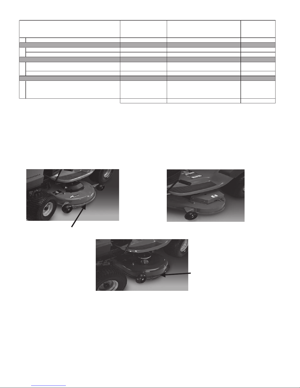
Consumer Wheeled Limited Warranty Chart 2012 Exhibit A
)
p
Consumer (personal,
household use only)
Spreader 1 Year 1 Year 1 Year
Product/Com
Robotic Mowers
Robotic Mower 2 Years 90 days 90 days
Battery 1 Year 1 Year 1 Year
Parts & Accessories (if purchased)
Accessories (e.g., grass catcher, bumper guard
accessories, etc.
Parts (e.g., belts, blades, etc.) 30 days No Warranty No Warranty
Parts & Accessories (if replaced in Warranty Service)
Replacement parts and/or accessories provided
under this Limited Warranty are warranted only for
the BALANCE of the warranty period applicable to
the part or accessory that was replaced.
* See Separate Engine Manufacturer's or Manufacturer's warranty. LCT Engines on specific Snow Throwers & Tillers, warranty through
Husqvarna.
** See reference 1 (b) of the warranty statement.
RZ - Two (2) Year Consumer warranty, parts & labor, with Hydro-Gear Distributor network.
EZ - One (1) Year Commercial warranty, parts & labor, with Husqvarna.
Two (2) Year Consumer warranty, parts & labor, with Hydro-Gear Distributor network.
MZ - Two (2) Year Commercial warranty, parts & labor, with Hydro-Gear Distributor network.
*** "Limited Lifetime Warranty" on Tiller tines and Fabricated Deck shell is for the life of the product or 7 (seven) years after the last date of the
complete unit's final production, whichever comes first. Deck Shell replacement will be limited to a maximum of two (2) decks within the Limited
Lifetime Warranty.
onent
1 Year No Warranty No Warranty
See to left See to left See to left
Consumer Commercial Rental
Commercial (any commercial,
professional, institutional, agricultural, or
income producing use, other than
Rental Use
Rental (any
rental usage)
Armor Protected Stamped Deck Shell Example Below Fabricated Deck Shell Example Below
Armor Protected
Stamped Deck Shell
Reinforced area
Stamped Deck Shell below, NOT reinforced
No reinforced area
22
Page 23
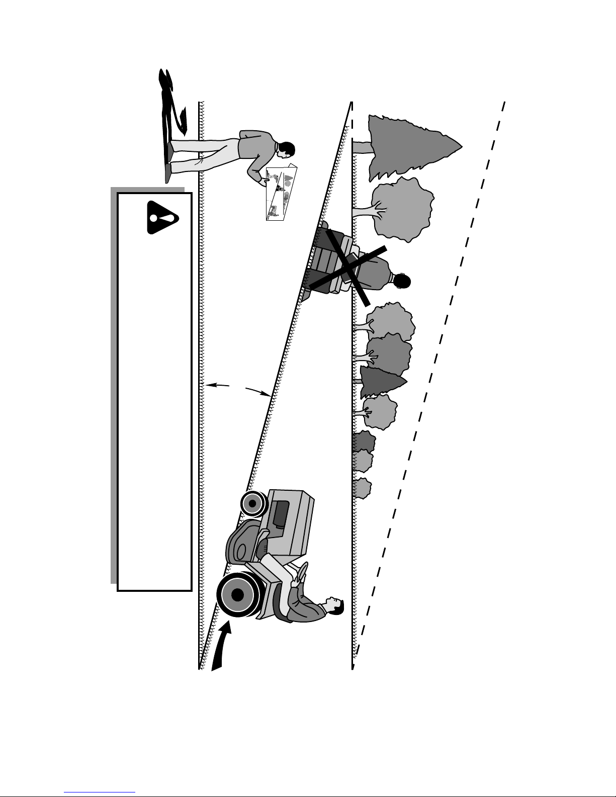
15 DEGREES MAX.
FOLD ALONG DOTTED LINE
THIS IS A 15 DEGREE SLOPE
ONLY RIDE UP AND DOWN HILL,
NOT ACROSS HILL
SUGGESTED GUIDE FOR SIGHTING SLOPES FOR SAFE OPERATION
WARNING: To avoid serious injury, operate your tractor up and
down the face of slopes, never across the face. Do not mow
slopes greater than 15 degrees. Make turns gradually to prevent
tipping or loss of control. Exercise extreme caution when
changing direction on slopes.
1. Fold this page along dotted line indicated above.
2. Hold page before you so that its left edge is vertically parallel to a tree
trunk or other upright structure.
3. Sight across the fold in the direction of hill slope you want to measure.
4. Compare the angle of the fold with the slope of the hill.
23
Page 24

05/01/2013 JM/TH
 Loading...