

Page 1
EN
Operator´s manual p.3
Please read the operator’s manual carefully and make sure you
understand the instructions before using the machine.
DE
NL
IT
Bedienungsanweisung p. 21
Lesen Sie die Bedienungsanweisung sorgfältig durch und machen Sie
sich mit dem Inhalt vertraut, bevor Sie das Gerät benutzen.
Gebruiksaanwijzing p. 39
Neem de gebruiksaanwijzing grondig door en gebruik de machine
niet voor u alles duidelijk heeft begrepen.
Istruzioni per l’uso p. 61
Prima di usare la macchina, leggere per intero le istruzioni per l’uso
e accertarsi di averne compreso il contenuto.
FS 700 EX
EN DE NL IT
HUSQVARNA CONSTRUCTION PRODUCTS
Page 2

Page 3

11
14
16
17
Operator’s Manual
Contents
English
Contents
Key to symbols
Safety Instructions
Introduction
Technical data
Operation
........................................................................
Before cutting
Assembling/Replacing the blade
Connecting the machine
Sawing
...........................................................................
Stop cutting
Transport
........................................................................
Maintenance
..............................................................
......................................................
......................................................................
.............................................................
..............................................................
.......................................
..................................................................
.................................................................
.......................
5
6
7
10
11
11
12
13
15
Trouble shooting
.......................................................
EU declaration of conformity
.............................
English - 3
19
Page 4

Contents
Operator’s Manual
4 - English
Page 5
Operator’s Manual FS 700EX
CE
Key to symbols
The symbols below are used on the machine and in this
Operator's Manual. It is important that the user
understands the significance of these in order to work with
the machine safely.
Manual
Please read the Operator's Manual carefully and
understand the contents before the machine is started.
Protective equipment
Always wear:
• Approved protective helmet.
• Approved hearing protection.
• Approved protective glasses or a visor, and other
essential safety equipment.
Attention
A hand with a raised index finger with the text “Attention”
signifies that a described element demands extra
attention.
This symbol indicates that the machine conforms to
applicable EU directives.
Electrical Warning
This symbol warns that there is high voltage present
Warning
A large warning triangle with the text “Warning” signifies
that there is a risk of serious personal injury or even
death.
Note
A smaller warning triangle with the text “Note” signifies
that there is a risk of minor personal injury or damage to
the machine.
Environmental Information
The symbol on the product or on its packaging indicates
that this product may not be treated as household waste.
Instead it shall be handed over to the applicable collection
point for the recycling of electrical and electronic
equipment.
By ensuring this product is disposed of correctly, you will
help prevent potential negative consequences for the
environment and human health, which could otherwise be
caused by inappropriate waste handling of this product.
For more detailed information about recycling of this
product, please contact your local council office, your
household waste disposal service or the shop where you
purchased the product.
English -
5
Page 6
Safety Instructions
During the design and production of Husqvarna products,
great importance is placed on safety, as well as
effectiveness and ease of use. To ensure that the
machine remains safe you must pay attention to the
following points:
• Note that under no circumstances may the machine be
started without following the safety instructions. Should
the user fail to comply with these, Husqvarna Construction Products Sweden AB or its representatives
are free from all liability both directly and indirectly.
Read through these operating instructions and make
sure that you understand the contents before starting
to use the machine. Should you, after reading these
safety instructions, still feel uncertain about the safety
risks involved you must not use the machine
Please contact your dealer for more information.
• Check that all couplings, connections and the blade
guard are in full working order.
• Make sure that all hoses and electrical cables are
connected to the machine correctly before you start the
machine.
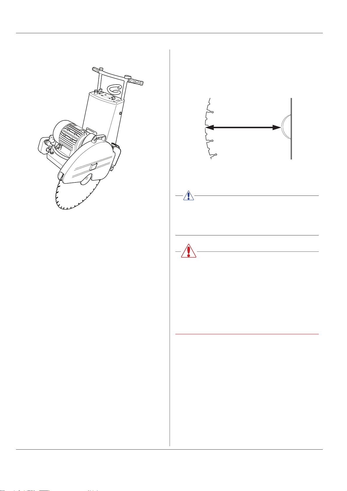
• The safety distance is 4 metres in front of and to the
side of the saw.
Operator’s Manual FS 700EX
• People that need to be in close proximity of the
machine must wear hearing protection.
• The machine must not be turned, swung or moved
laterally with the blade rotating.
• Only use blades recommended by the manufacturer.
• Never saw without a blade guard.
• Never saw without coolant. A poorly cooled blade can
cause segments to come loose from the blade. The
water coolant also binds concrete dust.
• Never use a damaged or worn blade.
• Do not use the machine if it is not working properly.
• Regulations for the prevention of accidents, and other
general safety and occupational health regulations,
must always be followed.
• Store the machine in a locked space away from
children and adults untrained in use of the machine.
• Firmly secure or anchor concrete blocks that have
been cut loose. The heavy weight of cut material can
cause extensive damage if it is not moved under
controlled conditions.
• Make sure that there is always another person close at
hand when you use the machines, so that you can call
for help if an accident should occur.
• Make sure that there are no persons or animals in the
working area.
• Check that the blade guard and blade flange guard are
fitted correctly.
• Always saw in a manner that permits easy access to
the emergency stop.
• Never leave the machine unsupervised with the engine
running.
• Clearly mark out all cuts to be made on the floor before
you start sawing, plan these so they can be carried out
without danger to persons or the machine.
• Check with the construction drawings whether there
are electrical cables, water mains, gas pipes or
drainage pipes within the working area.
• Check that electrical cables within the working area are
not live.
• Observe care when lifting. You are handling heavy
parts, which implies the risk of crush injuries or other
injuries.
• Personal protective equipment according to the
Operator's Manual must always be used and you
should use protective clothing too. Never wear loose
fitting clothes that can catch in moving parts.
WARNING!
Always use approved protective clothing
and approved protective equipment when
using the machine. Protective clothing and
protective equipment cannot eliminate
accident risks, but by using the right
clothes and equipment you can reduce the
seriousness if an accident should occur.
Ask your dealer about approved and
recommended protective clothing and
protective equipment.
6 - English
Page 7
Operator’s Manual FS 700EX
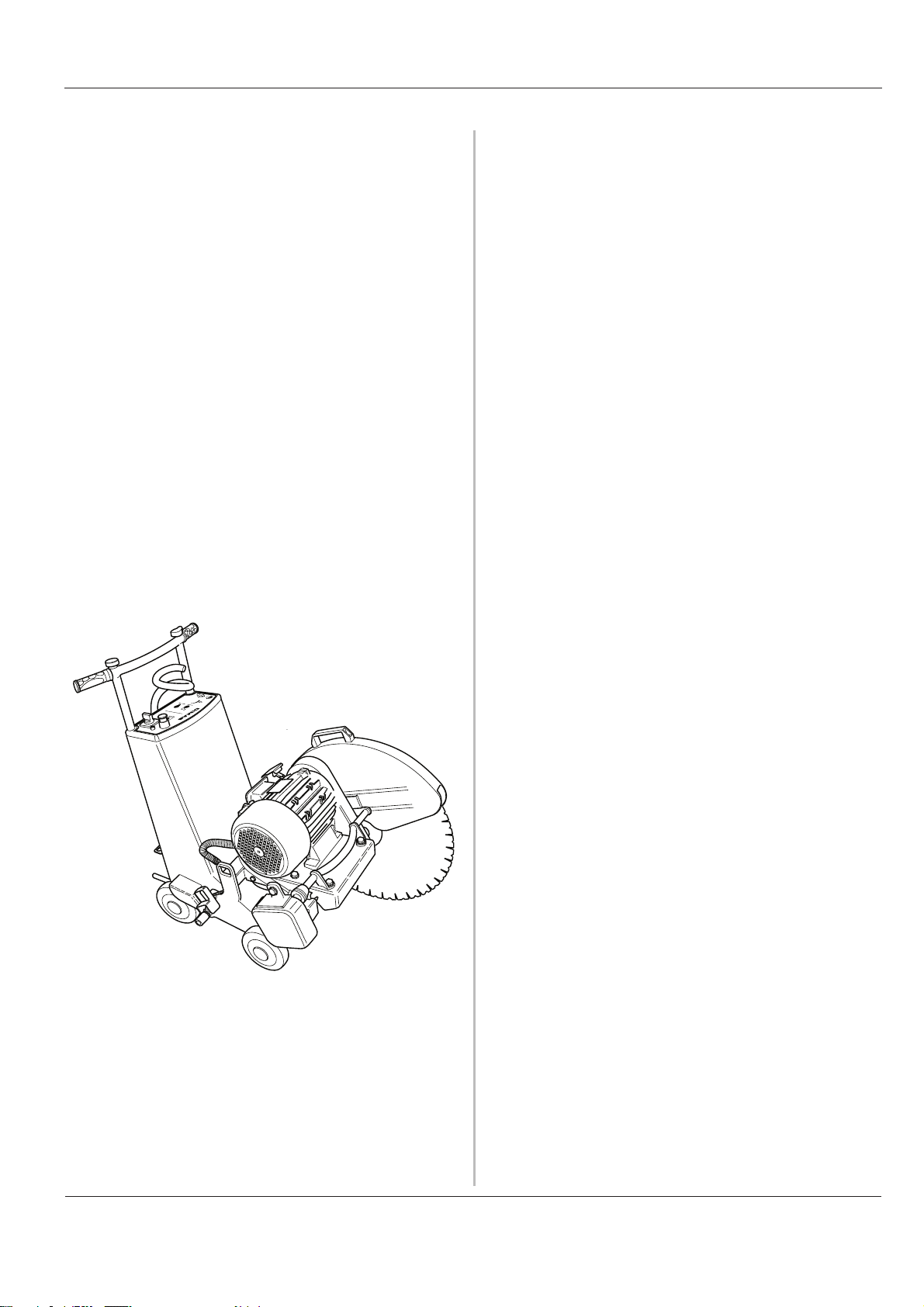
Introduction
The FS series is a new series of electrically powered floor
saws from Husqvarna. The aim during development has
been to create a powerful, yet easy to handle machine for
cutting reinforced concrete, brick and other stone material.
The machine should also be easy to use for one person.
The FS series features electrical trolley feed and blade
feed. These are both controlled by a lever fitted on the
adjustable handle.
The handle can be folded down into the saw and the
cutting bridge can easily be removed to facilitate transport.
This means it is easier to lift the saw, and it takes up less
space.
A saw is supplied with a flange and blade guard. A flush
cutting blade flange and a flush cutting blade guard are
available as accessories.
In order to use this machine as effectively as possible, it is
important that as the user you read through this Manual
carefully. In the event of uncertainty concerning any
details these should be discussed with your dealer before
you start to use the machine.
English -
7
Page 8
What is what
12
10
11
13
Operator’s Manual FS 700EX
12
5
3
4
11
7
6
9
8
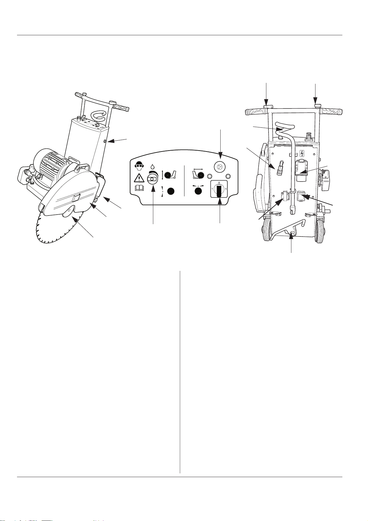
1. Trolley feed lever
The machine's propulsion is controlled using this lever.
The machine is driven forwards by turning the lever
clockwise. When the lever is turned anticlockwise, the
machine reverses. When lever is in the neutral position
the machine stands still. This function works as soon
as the machine is connected to the power and the
machine's propulsion is engaged.
2. Blade feed lever
This lever is used to raise and lower the cutting bridge.
The blade is fed downwards when the lever is turned
anticlockwise. When the required cutting depth is
achieved the lever is turned to the neutral position.
The blade is raised by turning the lever clockwise.
This function works as soon as the machine is
connected to the power.
3. Water selector
Turn this knob anticlockwise to open the water valve.
Water is led through the blade spindle and out to the
blade flange, where the water cools the blade and
prevents dust build-up.
10
5. Emergency stop
Cuts all power to the machine. No functions can be
activated until the emergency stop has been reset. The
emergency stop is reset by pulling out the button.
6. Power supply
For connecting an electrical connector of the type:
5-way 400 V/16A
4-way 480V/16 A.
4-way 600V/16A
7. Water connector
Water coolant is connected to the machine here.
8. 1-Phase 230V outlet Socket
To connect a 230V tool to the machine.
9. Personel protection
Will cut the power to the 1-phase outlet socket at 30
mA earth fault.
10.Propulsion/Parking brake
4. Start knob
Used to start the blade.
8 - English
When the foot lever is in the illustrated position the
drive is engaged. When the foot lever is in this position
Page 9
Operator’s Manual FS 700EX
and the trolley feed lever is in the neutral position or
the machine is not voltage fed, this position acts as a
parking brake.
If the foot lever is switched to the other position no
gear is engaged and the machine is easy to move. Use
this position when the machine needs to be
transported over long distances.
11.Hose holder
15.Handle setting
The height of the handle can be adjusted by loosening
these two screws to the most suitable height.
16.Adjuster screw
Adjust this screw to tension the drive belt.
14
The user can use the hose holder to prevent hoses
and cables trailing behind the machine. These will lie
to the side of the machine instead.
12.Blade guard
Can be fitted on either the right or left-hand side of the
machine as required. The guard can be secured in the
upright position by using the lever on the rear edge of
the guard.
13.Splash guard
The machine is equipped with a folding splash guard to
minimise water spray and dirtying. When the machine
is transported over long distances the splash guard
should be folded up and secured using the spring on
the blade guard. The splash guard should always be
folded down when cutting.
14.Blade flange
The blade flange fits on either side of the machine to
allow the blade to be easily fitted on both sides of the
machine
The blade flange should be covered with the blade
flange guard when a blade is not fitted The blade
flange guard is fitted on the right-hand side on delivery.
The machine is supplied with a standard blade flange.
A flush cutting blade flange can be purchased as an
option. Fit the blade on the flush cutting blade flange
when the cut is to be made next to a wall. A special
flush cutting blade guard must be used when cutting
flush.
English -
9
Page 10
Technical data
Operator’s Manual FS 700EX
Max. cutting depth:
600 mm (23") blade diameter__________ 235 mm (9.25")
625 mm (24") blade diameter__________ 248 mm (9.76")
700 mm (28.6") blade diameter ________ 285 mm (11.2")
725 mm (29") blade diameter__________ 298 mm (11.7")
We recommend that Husqvarna W1100 series blades are
used together with the machine
Weight (excl. blade): _____________ 155 kg
Weight (incl. blade):______________
Power: ___________________________ 7.5 kW
Voltage: __________________________ 400V/3 phase/50 Hz
Type of current _____________________ 16 A
Max. speed drive shaft: ______________ 1780 rpm
Periphery speed, saw blade___________ 56 m/s
Maximum blade diameter_____________ 725 mm
max. cutting depth __________________ 298 mm
150 kg
480V/3 phase/60 Hz
600V/3 phase/60 Hz
NOTE
When unsure about the significance of the
technical specifications or when ordering
spare parts please contact your dealer.
WARNING!
Under no circumstance may the machine
be modified without written permission
from Husqvarna Construction Products
Sweden AB. Non approved modifications
put you and others at risk of serious or
fatal injuries. Husqvarna Construction
Products Sweden AB bears no
responsibility for operations or measures
that do not follow these instructions.
10 - English
Page 11
Operator’s Manual FS 700EX
Operation
Before cutting
NOTE!
Follow the safety precautions.
Check that the correct power cable is connected to the
saw.
Check that the coolant water coupling on the hose is the
same as the type fitted on the machine.
Enclose the area to be cut so that unauthorised persons
can not be injured or disturb the operator while working.
Clearly mark out all cuts to be made on the floor before
you start sawing, plan these so they can be carried out
without danger to persons or the machine.
In order to prevent stoppages and sources of irritation
while cutting, plan the work so that you fit the blade to the
most appropriate side of the machine from the outset.
Check that you have the right saw blade for the machine
and the material to be cut. See the technical data.
WARNING!
Carefully check that all electrical power
cables, water pipes and gas pipes are
marked out within the cutting area. To cut
into a gas pipe that has not been emptied
is directly associated with mortal danger.
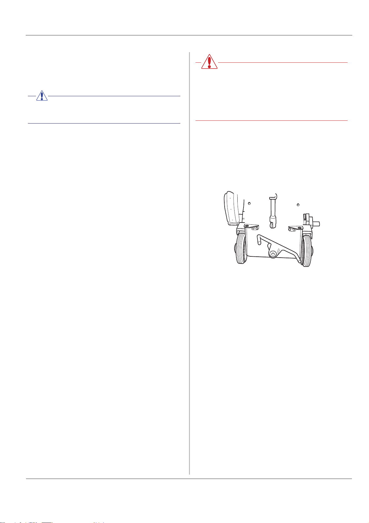
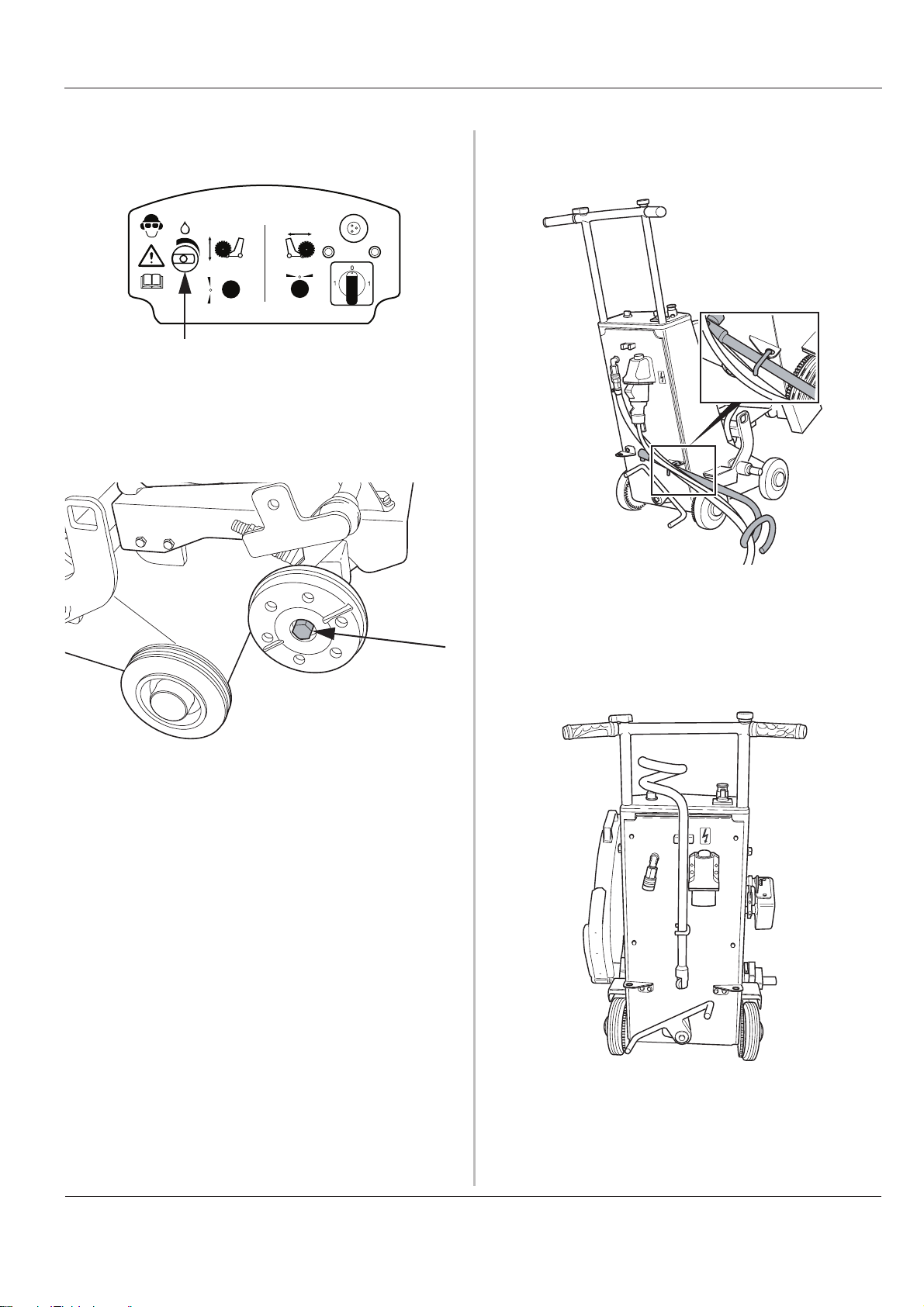
Assembling/Replacing the blade
• Lift up the cutting bridge to its highest position.
• Disconnect the incoming electrical connection.
• Engage the machine's propulsion by moving the foot
lever as illustrated below.
Check that the saw blade is not worn. The blade is worn
when only a few millimetres of the diamond segment
remains or when the diamond segment is not wider than
the body of the blade.
Check that the blade guard is not damaged or broken. A
broken or damaged blade guard must never be used.
Ensure you are fully conversant with how machine's
control levers work before starting the machine.
Make sure that the emergency stop is not blocked. The
emergency stop must not be blocked or covered while
working.
Check that the trolley feed, and blade feed levers are in
the neutral position.
Remove all foreign objects in the path of the machine that
can damage the machine or the surroundings.
Check that there are no unauthorised persons within the
safety zone, i.e. 4 metres in front of or to the side of the
machine.
Make sure that persons in the vicinity of the machine wear
hearing protection and protective glasses.
Move the machine so the blade follows the pre-drawn
cutting line.
• Fold up the blade guard and secure it in the raised
position by using the blade guard holder.
• Clean the blade flanges and check that they are not
damaged.
• Assemble the saw blade and check that the direction
of rotation corresponds with the arrow on the blade
guard. If the direction of rotation is not marked on the
body of the blade, the blade's direction of rotation must
be determined with the help of the wear on the
diamond segments, the exposed part of the diamond
should then be in the direction of rotation.
• Tighten the blade flange using the supplied spanner so
hard that it is well secured. At least 70 Nm.
• Fold down the blade guard.
• Check that the saw blade rotates freely and easily by
turning it by hand, and that no abnormal noise occurs
when the saw blade is rotated. Also check that the saw
blade is straight. Never cut with a damaged saw blade.
Check your safety equipment and any protective clothing.
English -
11
Page 12
Operator’s Manual FS 700EX
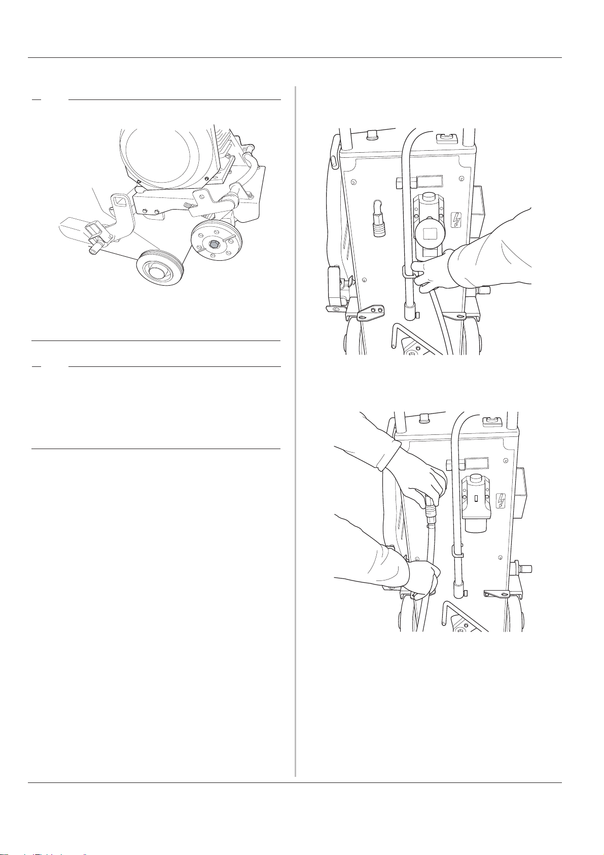
Connecting the machine
Attention
Remember that the screw securing the righthand blade flange has a left-hand thread.
Connect the power cable to the electrical socket.
3 x 380-420 V
A 50 Hz
16
Attention
The blade should be assembled on the
machine's left-hand side when possible. This
is because assembly on the right-hand side
affects motor cooling.
Connect the coolant hose to the right coupling.
3 x 380-420 V
A 50 Hz
16
12 - English
Page 13
Operator’s Manual FS 700EX
Turn on the water coolant so that sufficient cooling is
obtained and dust build-up is prevented.
Check that the water supply is ample and that the nozzles
are not clogged. Also check that the set screw is fitted in
the end of the blade spindle where no blade is fitted
.
Make sure that the machine's power cable and water
supply can not end up under the machine or are in the
way by using the hose holder.
Make sure that the saw blade rotates freely before starting
the machine.
Sawing
Activate the propulsion by moving the foot lever as
illustrated with your foot. The machine will not start to
move until the trolley feed lever is moved from the neutral
position.
English - 13
Page 14

Operator’s Manual FS 700EX
Start blade rotation by turning the switch towards the lamp
that is on. If the switch is turned in the opposite direction
the blade will rotate in the wrong direction.
0
1
Feed the saw blade by turning the blade feed lever
towards you, so that a cutting depth adapted to the floor
material, however at least 20 mm, is realized.
Make a pilot cut at an even speed at this depth along the
pre-drawn line. When the complete pilot cut has been made,
raise the blade, shut off the water coolant and stop the blade
rotating. Reverse the machine to the starting point.
1
Stop cutting
Lift up the cutting bridge to its highest position.
Shut down blade rotation by turning the switch the neutral
position.
Turn both the travel feed and blade feed to their neutral
positions.
Shut off the water coolant.
NOTE!
The protective devices are for your own
safety, consequently, it is extremely important
to check all safety equipment regularly. Should
a fault be discovered, please contact your
dealer.
Align the machine with the pilot cut again and start the
machine as above.
Lower the saw blade to a suitable cutting depth (5-10 cm).
A suitable cutting depth varies depending on the floor
material and the speed.
A simple rule is if the machine tends to “climb up” out of
the pilot cut the cutting depth is too large and/or the speed
too high.
The machine must not be driven faster than that it cuts
without “climbing” i.e. that the machine's front wheels lift
off from the ground. If the machine “climbs”, decrease the
trolley feed by turning the lever for the travel feed
anticlockwise or raise the blade by turning the blade feed
lever clockwise
NOTE!
The operator must always be behind the
machine when cutting and within reach of the
levers and stop.
WARNING!
Contact with the rotating saw blade can
result in serious, physical injury or even
death.
14 - English
Page 15
Operator’s Manual FS 700EX
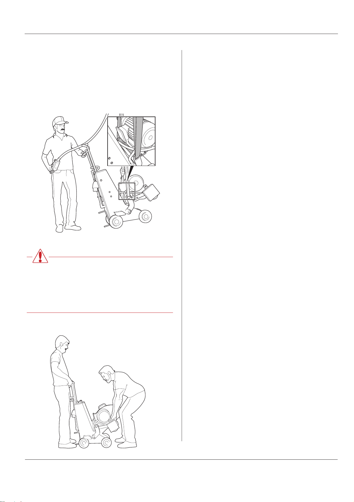
Transport
The blade must be removed from the saw during all
transport and lifting. If the blade is not removed, there is a
risk it will be damaged.
The saw can be lifted in several different ways during
transport. When the saw is lifted using a crane, secure the
lifting strap in the lifting eyes.
WARNING!
Pay attention to ensure that you or anyone
else never stands under a free hanging
machine. Should you be hit by a falling
machine, this can result in death or serious
physical injury.
When the saw is only lifted a little, it can be lifted from the
handles and the front lifting stay.
English - 15
Page 16
Operator’s Manual FS 700EX
Maintenance
Once cutting has been completed the machine should be
cleaned. Make sure that the electrical connection has
been disconnected before washing. Avoid spraying water
against the electric motor and electrical connections. Use
a dish-brush or sponge to clean the machine.
Attention
Avoid cleaning the machine with a high
pressure washer.
Check the condition of the saw blade regularly for signs of
wear or damage. When segments are worn or the width of
the segments is nearly the same as the body of the blade,
it should be replaced.
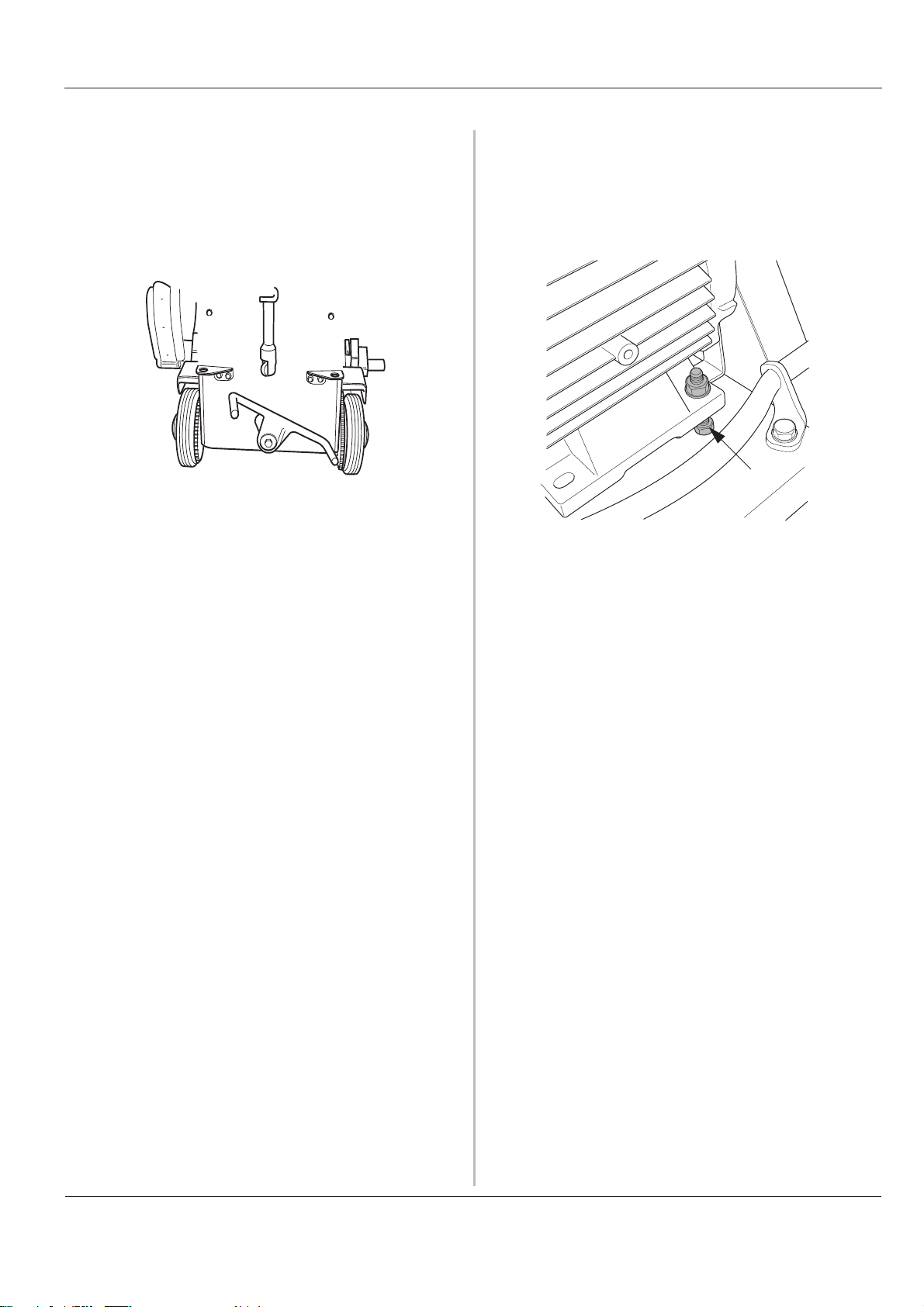
Check regularly that electrical cables, couplings, drive belt
and screw joints are not damaged.
Check regularly that the drive belt and couplings are not
dirty and that the drive belt is not tensioned too little or too
much. The guard around the drive belt must be removed
in order to check the drive belt tension.
Tension the drive belt, if necessary, by first loosening the
nut (a), hold the nut under the base with a spanner and
then turn the bolt (b) until the belt is tensioned. When the
belt is tensioned, lock by screwing back the nut.
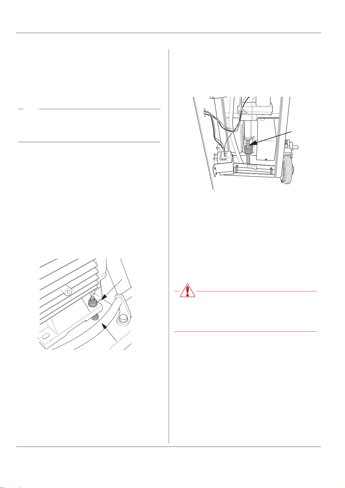
Periodically lubricate the nut for the blade feed. The rear
of the machine must be dismantled first to gain access to
the nut.
Once the rear has been removed, grease the feed screw
a few centimetres above and under the nut.
Refit the rear as follows:
1. Hang the cover from the top edge.
2. Pull a part the cogs that drive the saw forwards by
inserting a screwdriver between the cogs and carefully
pressing the screwdriver downwards.
At the same time press the rear against the saw's
chassis.
a
b
When storing the machine for long periods it must be
cleaned carefully and the water tank emptied.
3. Refit the screws that hold the rear in position.
WARNING!
The electrical connection must be
disconnected before carrying out
maintenance repairs and service-work
16 - English
Page 17

Operator’s Manual FS 700EX
Trouble shooting
If a fault occurs, first check whether it coincides with any of
the possible faults in the trouble shooting guide below.
If the fault coincides with one of the fault possibilities in the
NOTE
trouble shooting guide, contact your dealer for further
information.
Before rectifying a fault, check that all
electrical connections are disconnected to
prevent the machine from starting during the
course of the work.
Fault Cause Action
The blade rotates in the wrong direction. The starter knob is defective. Turn the starter knob in the direction
indicated by the lit lamp.
The blade jams. Drive belt slips.
Drive belt dirty.
Drive belt worn.
No water is produced or too little water
reaches the blade.
The blade jams. The blade is worn.
The blade flange is dirty Clean the blade flange.
The saw blade is clamped.
The saw has been fed too hard.
Tension the drive belt.
Clean the drive belt.
Replace the drive belt.
Increase the water pressure by opening
the water tap a little more.
Replace the blade.
Support the saw block with braces or a
jack.
Run with either a lower feed rate or
shallower cutting depth.
The motor does not start. The emergency stop has been switched
on.
Electrical fault.
There is no trolley feed. The drive shaft is not engaged. Change the foot lever for propulsion so
There is no trolley feed/blade feed. The feed levers were not reset when the
power was connected.
There is no blade feed up or down. The feeder nut has jammed at the end
position.
The feed nut is dry.
The machine cuts out / does not start
blade rotation.
Both status lamps for blade rotation are
on.
The thermal cut-out on the motor has
tripped.
A phase is down. Check the fuses and electrical power
Reset the emergency stop.
Contact your dealer.
that the drive shaft is engaged.
Reset the machine by turning off the
blade rotation, pressing down the
emergency stop and turning the levers to
the neutral position. Wait 3 seconds and
then reset the emergency stop button.
Remove the rear cover and carefully
loosen the feed nut by turning the nut at
the bottom of the feed screw.
Grease the feed axle.
Wait until the motor has cooled. Once the
temperature of the motor has dropped
the saw is started again as normal.
cable.
English - 17
Page 18

Operator’s Manual FS 700EX
18 - English
Page 19

Operator’s Manual FS 700EX
EU declaration of conformity
Husqvarna Construction Products Sweden AB, Box 2098, 550 02 Jönköping, Sweden, tel:
036-570 60 00, hereby declares that its FS 700E floor saw, from serial number 01001
onwards, is manufactured in compliance with the Council's machinery directive 98/37/EC,
low-voltage directive 73/23/EEC and EMC directive 89/336/EEC, including subsequent
amendments, and that the following standards have been used for guidance: EN 55 014-1,
EN 55 014-2, EN 61 000-3-2, EN 50 144-1, EN 13 862.
Jönköping 2005-01-01
Christer Carlberg
Managing Director
English - 19
Page 20

Operator’s Manual FS 700EX
20 - English
Page 21

Bedienungsanleitung FS 700EX
Inhalt
Deutsch
Inhalt
Erklärung der Symbole.......................................... 23
Sicherheitsvorschriften
Einleitung
Was ist was?
....................................................................... 25
................................................................ 26
Technische Daten
Bedienung
Vor dem Sägen
...................................................................... 29
.......................................................... 29
Einbau/Austausch der Trennscheibe
Maschine anschließen
Schneiden
.................................................................... 31
Schneiden beenden
Transport
Wartung
........................................................................ 33
........................................................................... 34
......................................... 24
..................................................... 28
.............. 29
........................................... 30
................................................ 32
Fehlersuche
EU-Erklärung
................................................................. 35
................................................................ 38
Deutsch - 21
Page 22

Inhalt Bedienungsanleitung FS 700EX
22 - Deutsch
Page 23

Bedienungsanleitung FS 700EX
Erklärung der Symbole
Diese Symbole sind auf der Maschine und in der
Bedienungsanleitung angegeben. Um sicher mit der
Maschine arbeiten zu können, muss der Bediener ihre
Bedeutung verstehen.
Anleitung
Vor der Inbetriebnahme der Maschine lesen Sie die
Bedienungsanleitung aufmerksam durch und machen Sie
sich mit dem Inhalt vertraut.
Schutzausrüstung
Stets verwenden:
• Zugelassener Schutzhelm
• Zugelassener Gehörschutz
• Zugelassene Schutzbrille oder Gesichtsschutz sowie
sonstige erforderliche Schutzausrüstung.
Anmerkung
Eine Hand mit erhobenem Zeigefinger mit dem Zusatz
"Anmerkung" bedeutet, dass ein beschriebener Vorgang
zusätzliche Aufmerksamkeit erfordert.
CE
Dieses Symbol weißt darauf hin, dass die Maschine den
geltenden EG-Richtlinien entspricht.
Stromwarnung
Dieses Symbol warnt vor Hochspannung.
Warnung
Ein großes Warndreieck mit dem Zusatz "Warnung"
bedeutet, dass die Gefahr von schweren, sogar
lebensgefährlichen Verletzungen besteht..
Achtung
Ein kleines Warndreieck mit dem Zusatz "Achtung"
bedeutet, dass die Gefahr von leichteren Verletzungen
oder Maschinenschäden besteht.
Umweltinformation
Das Symbol auf dem Produkt bzw. auf der
Produktverpackung gibt an, dass dieses Produkt nicht als
Hausmüll behandelt werden darf. Zur Entsorgung ist es
an einen entsprechenden Recycling-Punkt für elektrische
und elektronische Geräte zu bringen.
Durch die umweltgerechte Entsorgung dieses Produkts
tragen Sie dazu bei, potentielle Folgeschäden an der
Umwelt und Gesundheitsschäden zu verhindern.
Ausführlichere Informationen über das Recycling dieses
Produkts erhalten Sie auf Wunsch von Ihrem Stadt- oder
Gemeinderat, den für die Hausmüllentsorgung
zuständigen Behörden oder dem Geschäft, in dem Sie
dieses Produkt gekauft haben.
Deutsch - 23
Page 24
Bedienungsanleitung FS 700EX
Sicherheitsvorschriften
Bei der Konstruktion und Herstellung von HusqvarnaProdukten wurde neben der Leistungsfähigkeit und
Benutzerfreundlichkeit größtes Gewicht auf die Sicherheit
gelegt. Folgende Punkte sind zu beachten, um einen
sicheren Maschinenbetrieb zu gewährleisten:
• Die Maschine darf ausschließlich unter Befolgung der
Sicherheitsvorschriften gestartet werden. Bei
Missachtung der Vorschriften seitens des Bedieners
haftet Husqvarna Construction Products Sweden AB
oder ihre Vertreter weder direkt noch indirekt.
Lesen Sie die Bedienungsanleitung aufmerksam durch
und machen Sie sich mit dem Inhalt vertraut, bevor Sie
die Maschine benutzen. Sollten Sie sich auch nach
Lektüre der Sicherheitsvorschriften nicht über die
vorliegenden Sicherheitsrisiken im Klaren sein, dürfen
Sie die Maschine nicht benutzen.
Ihr Fachhändler erteilt auf Anfrage gerne weitere
Informationen.
• Sicherstellen, dass alle Verbindungen, Anschlüsse und
der Trennscheibenschutz unbeschädigt sind.
arbeiten. Keine Kleidung tragen, die sich in den
beweglichen Teilen der Maschine verfangen kann.
• Personen, die sich in der Umgebung aufhalten,
müssen einen Gehörschutz tragen.
• Mit rotierender Trennscheibe darf die Maschine nicht
gedreht, gewendet oder seitlich bewegt werden.
• Nur vom Hersteller empfohlene Trennscheiben
verwenden.
• Niemals ohne Trennscheibenschutz schneiden.
• Niemals ohne Kühlwasser schneiden. Von einer
unzureichend gekühlten Trennscheibe können sich
Segmente lösen. Das Kühlwasser bindet darüber
hinaus Betonstaub.
• Niemals beschädigte oder verschlissene
Trennscheiben verwenden.
• Die Maschine nur verwenden, wenn sie einwandfrei
funktioniert.
• Unfallverhütungsvorschriften, sonstige Sicherheitsund arbeitsmedizinische Vorschriften sind jederzeit zu
beachten.
• Vor der Inbetriebnahme sicherstellen, dass alle
Schläuche und Stromkabel korrekt an der Maschine
angeschlossen sind.
• Vor und seitlich der Trennscheibe muss ein
Sicherheitsabstand von 4 m eingehalten werden.
• Sicherstellen, dass sich im Arbeitsbereich keine
Personen oder Tiere aufhalten.
• Sicherstellen, dass Trennscheibenschutz bzw.
Trennscheiben-Flanschschutz korrekt montiert sind.
• Stets so arbeiten, dass der Nothalt schnell und einfach
zu erreichen ist.
• Niemals die Maschine unbeaufsichtigt mit laufendem
Motor stehen lassen.
• Vor dem Schneiden sind alle auszuführenden Schnitte
deutlich auf dem Boden zu markieren und zu planen,
sodass sie ohne Gefahr für Mensch oder Maschine
durchgeführt werden können.
• Anhand von Bauzeichnungen prüfen, ob Stromkabel,
Wasser-, Gas- oder Abflussleitungen im Arbeitsbereich
verlegt sind.
• Sicherstellen, dass die Stromkabel im Arbeitsbereich
nicht stromführend sind.
• Vorsicht beim Heben. Schweres Gerät bedeutet
Klemmgefahr und Gefahr für andere Verletzungen.
• Die Maschine in einem verschlossenen Raum
abstellen, der für Kinder sowie für Erwachsene ohne
besondere Ausbildung für die Verwendung der
Maschine unzugänglich ist.
• Abgesägte Betonblöcke ausreichend sichern oder
verankern. Freigesägte Materialien mit hohem Gewicht
können schwere Schäden verursachen, wenn sie nicht
kontrolliert bewegt werden können.
• Beim Arbeiten mit den Maschinen muss stets eine
weitere Person anwesend sein, die bei Unfällen
Hilfestellung leisten kann.
WARNUNG!
Bei Benutzung der Maschine stets zugelas-
sene Schutzkleidung und zugelassene
Schutzausrüstung tragen. Schutzkleidung
und Schutzausrüstung können die Verletzungsgefahr nicht völlig eliminieren, doch
lässt sich im Unglücksfall der Ernst eventueller Verletzungen durch die richtige Kleidung und angemessene Ausrüstung
reduzieren. Ihr Händler informiert Sie über
empfehlenswerte, zugelassene Schutzausrüstung und -kleidung.
• Niemals ohne eine persönliche Schutzausrüstung
(siehe Bedienungsanleitung) und Schutzkleidung
24 - Deutsch
Page 25

Bedienungsanleitung FS 700EX
Einleitung
Die FS-Serie ist eine neue Reihe mit elektrischen BodenTrennschleifern von Husqvarna. Wir wollten eine
leistungsfähige, handliche Maschine für das Schneiden in
armiertem Beton, Backstein und anderen Steinmaterialien
entwickeln. Die Maschine sollte für eine Person leicht zu
bedienen sein.
Die FS-Serie ist mit elektrischem Längs- und
Tiefenvorschub ausgerüstet. Beide werden mit Reglern
bedient, die sich am einstellbaren Handgriff befinden.
Um den Transport des Trennschneiders zu erleichtern,
kann der Handgriff heruntergeklappt und die
Schneideinheit auf einfache Art abgenommen werden. So
lässt sich das Gerät leichter heben und nimmt beim
Transport weniger Platz in Anspruch.
Zum Lieferumfang des Trennschleifers gehören ein
Flansch und ein Trennscheibenschutz. Als Zubehör sind
ein Flachschneideflansch und ein Flachschneideschutz
erhältlich.
Diese Bedienungsanleitung ist aufmerksam
durchzulesen, nur so lässt sich die Maschine so effektiv
wie möglich einsetzen. Bei Unklarheiten oder Fragen
wenden Sie sich bitte an Ihren Händler, bevor Sie die
Maschine in Gebrauch nehmen.
Deutsch - 25
Page 26

Bedienungsanleitung FS 700EX
Was ist was?
12
15
13
12
3
14
1. Längsvorschubregler
Mit diesem Regler wird der Vorwärtsantrieb geändert.
Regler im Uhrzeigersinn drehen, um vorwärts zu
fahren. Regler im Gegenuhrzeigersinn drehen, um
rückwärts zu fahren. Mit dem Regler in der Nullstellung
steht die Maschine still. Diese Funktion ist bereit,
sobald die Maschine mit Strom versorgt und der
Vorwärtsantrieb aktiviert ist.
2. Tiefenvorschubregler
Mit diesem Regler wird die Schneideinheit angehoben
und gesenkt. Der Tiefenvorschub der Trennscheibe
erfolgt durch Drehen des Reglers im
Gegenuhrzeigersinn. Ist die gewünschte Schnitttiefe
erreicht, wird der Regler in die Nullstellung
zurückgestellt. Regler im Uhrzeigersinn drehen, um die
Trennscheibe anzuheben. Diese Funktion ist bereit,
sobald die Maschine mit Strom versorgt ist.
3. Wasserregler
Regler im Gegenuhrzeigersinn drehen, um das
Wasserventil zu öffnen. Das Wasser wird durch die
Trennscheibenachse und zum Trennscheibenflansch
geleitet, wo es die Trennscheibe kühlt und eine
Staubbildung verhindert.
5
4
4. Startschalter
Wird für den Start der Trennscheibenrotation verwendet.
5. Nothalt
Unterbricht die gesamte Stromzufuhr zur Maschine.
Sämtliche Funktionen können erst aktiviert werden,
wenn der Nothalt zurückgestellt wird. Der Nothalt wird
durch Herausziehen des Knopfs zurückgestellt.
6. Stromanschluss
Für folgenden Stromanschlusstyp:
5-polig, 400 V/16 A
7. Wasseranschluss
Hier wird Kühlwasser an die Maschine angeschlossen.
8. 1-Phasen 230-V-Anschluss
Um 230-V-Werkzeug an die Maschine anzuschließen.
9. Personenschutz
Unterbricht den Strom zum 1-Phasen-Anschluss bei
30 mA Stromverlust.
10.Vorwärtsantrieb/Feststellbremse
Befindet sich der Arm in der abgebildeten Position, ist
der Antrieb aktiviert. Befindet sich der Arm in dieser
Position und der Längsvorschubregler ist nullgestellt
11
7
8
10
6
9
26 - Deutsch
Page 27

Bedienungsanleitung FS 700EX
oder die Maschine ist stromlos, fungiert die Stellung
als Feststellbremse.
Wird der Arm in die andere Position bewegt, ist kein
Gang eingelegt und die Maschine lässt sich leicht
bewegen. Diese Stellung wählen, wenn die Maschine
über längere Strecken bewegt werden soll.
11.Schlauchhalter
Durch Verwendung des Schlauchhalters wird
vermieden, dass Schläuche und Kabel hinter der
Maschine hergezogen werden. Sie befinden sich
stattdessen seitlich von der Maschine
12.Trennscheibenschutz
Kann je nach Wunsch auf der rechten oder linken
Seite der Maschine angebracht werden. Der Schutz
kann in aufrechter Lage mit dem Hebel an der hinteren
Kante gesichert werden.
13.Spritzschutz
Um Wasserspritzer und Verschmutzung zu minimieren,
ist die Maschine mit einem klappbaren Spritzschutz
ausgestattet. Soll der Trennschleifer über längere Strekken transportiert werden, muss der Spritzschutz nach
oben geklappt und mit der Feder am Trennscheibenschutz befestigt werden. Beim Schneiden muss der
Spritzschutz stets nach unten geklappt sein.
14.Trennscheibenflansch
Um auf einfache Weise die Trennscheibe auf der
gewünschten Seite der Maschine montieren zu können, passt der Trennscheibenflansch an beide Seiten.
Der Trennscheibenflansch ohne montierte Scheibe ist
mit dem Trennscheibenflanschschutz zu bedecken,
der sich bei Lieferung auf der rechten Seite befindet.
Die Maschine wird mit einem herkömmlichen Trennscheibenflansch geliefert. Ein Flachschneideflansch ist
als Zubehör erhältlich. Die Trennscheibe am Flachschneideflansch anbringen, wenn der Schnitt an einer
Wand liegen soll. Beim Flachschneiden muss der spezielle Flachschneideschutz verwendet werden.
15.Handgriffeinstellung
Durch Lösen dieser beiden Schrauben kann der
Handgriff auf die gewünschte Höhe eingestellt werden.
16.Stellschraube
Diese Schraube justieren, um den Antriebsriemen zu
spannen.
16
17.Motorhalterung
Durch Lösen dieser beiden Schrauben kann die
Schneideinheit mit Motor abgehoben werden, um das
Maschinengewicht zu reduzieren.
17
Deutsch - 27
Page 28

Bedienungsanleitung FS 700EX
Technische Daten
Gewicht ohne Trennscheibe: _______ 155 kg
Gewicht mit Trennscheibe: ________
Motorleistung:______________________ 7,5 kW
Spannung: ________________________ 400 V/3 Phasen/50
Strom:____________________________ 16 A
Max. Drehzahl Antriebsachse: _________ 1780 U/min
Umfangsgeschwindigkeit, Trennscheibe: _ 56 m/s
Max. Trennscheibendurchmesser: ______ 725 mm
Max. Schnitttiefe: ___________________ 298 mm
150 kg
Hz
Max. Schnitttiefe:
600 mm (23") Trennscheibendurchmesser 235 mm (9,25")
625 mm (24") Trennscheibendurchmesser 248 mm (9,76")
700 mm (28,6") Trennscheibendurchmesser285 mm (11,2")
725 mm (29") Trennscheibendurchmesser 298 mm (11,7")
Wir empfehlen, Trennscheiben der Serie Dimas W1100
zusammen mit der Maschine zu verwenden.
ACHTUNG
Bei Unsicherheiten bezüglich der Bedeutung
der technischen Daten oder bei der Bestellung
von Ersatzteilen sprechen Sie bitte mit Ihrem
Händler.
WARNUNG!
Ohne die schriftliche Genehmigung von
Husqvarna Construction Products Sweden AB dürfen unter keinen Umständen
Veränderungen an der Maschine vorgenommen werden. Unzulässige Änderungen
bringen die Gefahr von schweren oder
lebensgefährlichen Verletzungen für Sie
und andere mit sich. Husqvarna Construction Products Sweden AB haftet nicht für
den Umgang mit oder Maßnahmen an der
Maschine, die diesen Anweisungen nicht
folgen.
28 - Deutsch
Page 29

Bedienungsanleitung FS 700EX
Bedienung
Vor dem Sägen
ACHTUNG!
Sicherheitsvorschriften beachten.
Sicherstellen, dass das richtige Anschlusskabel für den
Trennschleifer zur Verfügung steht.
Sicherstellen, dass der Kühlwasseranschluss des
Schlauchs mit dem an der Maschine übereinstimmt.
Den zu schneidenden Bereich einzäunen, damit keine
unbeteiligten Personen zu Schaden kommen oder den
Bediener bei der Arbeit stören können.
Vor dem Schneiden sind alle auszuführenden Schnitte
deutlich auf dem Boden zu markieren und zu planen,
sodass sie ohne Gefahr für Mensch oder Maschine
durchgeführt werden können.
Um Unterbrechungen und kritische Momente beim
Schneiden zu vermeiden, ist die Arbeit so zu planen, dass
die Trennscheibe von Anfang an auf der am besten
geeigneten Seite angebracht wird.
Sicherstellen, dass die korrekte Trennscheibe für die
Maschine und für den zu sägenden Untergrund verwendet
wird. Siehe Technische Daten.
Sicherstellen, dass Personen, die sich in der Umgebung
der Maschine aufhalten, Gehörschutz und Schutzbrille
tragen.
Die Maschine so bewegen, dass die Trennscheibe der
zuvor markierten Schnittlinie folgt.
Schutzausrüstung und Schutzkleidung müssen intakt
sein.
WARNUNG!
Genau prüfen, dass alle Strom-, Wasser-
und Gasleitungen im Schnittbereich
markiert sind. Sollte beim Schneiden eine
volle Gasleitung getroffen werden, ist dies
absolut lebensgefährlich.
Einbau/Austausch der
Trennscheibe
• Schneideinheit in die höchste Position bringen.
• Stromzufuhr unterbrechen.
• Vorwärtsantrieb der Maschine aktivieren, dazu den
Arm in die abgebildete Stellung bringen.
Sicherstellen, dass die Trennscheibe nicht verschlissen
ist. Eine verschlissene Trennscheibe ist daran zu
erkennen, dass die Resthöhe des Diamantsegments nur
2-3 mm beträgt oder das Segment nicht breiter ist als das
Stammblatt.
Sicherstellen, dass der Trennscheibenschutz nicht defekt
ist. Ein schadhafter Trennscheibenschutz darf niemals
verwendet werden.
Erst wenn Sie sich über die Funktion der Bedienelemente
der Maschine im Klaren sind, dürfen Sie die Maschine
starten.
Darauf achten, dass der Nothalt nicht blockiert wird. Der
Nothalt darf beim Betrieb nicht blockiert oder überdeckt
werden.
Sicherstellen, dass Längs- und Tiefenvorschubregler in
Nullstellung sind.
Alle fremden Gegenstände entfernen, die Maschine oder
Umgebung beschädigen können und im Weg sind.
Sicherstellen, dass sich keine Unbefugten innerhalb der
Sicherheitszone befinden, d. h. 4 m vor oder seitlich von
der Maschine.
• Trennscheibenschutz hochklappen und in dieser
Position mit dem Trennscheibenschutzhalter sichern.
• Trennscheibenflansche säubern und sicherstellen,
dass sie unbeschädigt sind.
• Trennscheibe einbauen und darauf achten, dass die
Drehrichtung mit dem Pfeil auf dem Trennscheibenschutz übereinstimmt. Ist die Drehrichtung nicht auf
dem Stammblatt angegeben, wird die Drehrichtung der
Trennscheibe mithilfe des Verschleißes der Diamantsegmente bestimmt, wobei der freigelegte Teil des Diamanten in Drehrichtung liegt.
• Trennscheibenflansch mit dem beiliegenden Schlüssel
fest anziehen, sodass er richtig fest sitzt. Mindestens
70 Nm.
Deutsch - 29
Page 30

Bedienungsanleitung FS 700EX
• Trennscheibenschutz herunterklappen.
• Trennscheibe von Hand drehen und sicherstellen,
dass sie sich frei und leicht drehen lässt und keine
ungewöhnlichen Geräusche auftreten. Auch darauf
achten, dass die Trennscheibe gerade sitzt. Niemals
mit einer defekten Trennscheibe arbeiten.
Anmerkung
Maschine anschließen
Stromkabel (400 V/16 A/3 Phasen/50 Hz) anschließen.
3 x 380-420 V
16 A 50 Hz
Daran denken, dass die Schraube, die den
rechten Trennscheibenflansch hält, ein
Linksgewinde hat.
Anmerkung
Die Trennscheibe sollte primär auf der linken
Maschinenseite montiert werden. Die
Montage auf der rechten Seite führt zu einer
Beeinträchtigung der Motorkühlung.
Kühlwasserschlauch mit dem vorgesehenen Anschluss
verbinden.
3 x 380-420 V
16 A 50 Hz
30 - Deutsch
Page 31

Bedienungsanleitung FS 700EX
Kühlwasser aufdrehen, sodass eine ausreichende
Kühlung erzielt und die Staubbildung vermieden wird.
Für eine reichliche Wasserzufuhr sorgen und darauf
achten, dass die Düsen nicht verstopft sind. Auch
sicherstellen, dass sich die Stoppschraube an dem Ende
der Trennscheibenachse befindet, an dem keine
Trennscheibe angeschraubt ist.
.
Sicherstellen, dass Stromkabel und Wasserversorgung
nicht unter die Maschine geraten oder im Weg sein
können; dazu den Schlauchhalter verwenden.
Die Trennscheibe muss sich frei drehen können, bevor die
Maschine gestartet wird.
Schneiden
Vorwärtsantrieb aktivieren, dazu den Arm mit dem Fuß in
die abgebildete Stellung bringen. Die Maschine bewegt
sich erst wieder, wenn der Regler für den Längsvorschub
aus der Nullstellung bewegt wird.
Deutsch - 31
Page 32

Bedienungsanleitung FS 700EX
Den Schalter in Richtung der leuchtenden Lampe drehen,
dann setzt die Rotation der Trennscheibe ein. Wird der
Schalter in die falsche Richtung gedreht, dreht sich auch
die Trennscheibe in der falschen Richtung.
WARNUNG!
Ein Kontakt mit der sich drehenden
Trennscheibe kann zu schweren
Verletzungen und sogar zum Tod führen.
0
Schneiden beenden
1
Regler für den Tiefenvorschub in Richtung Bediener
drehen und die Trennscheibe so einführen, dass eine dem
Bodenmaterial entsprechende Tiefe erreicht wird, jedoch
mindestens 20 mm.
Mit gleichmäßiger Geschwindigkeit eine Führungsnut in
dieser Tiefe und entlang der gesamten zuvor markierten
Linie schneiden. Ist die komplette Führungsnut
geschnitten, Trennscheibe anheben, Kühlwasser
abschalten und Trennscheibenrotation anhalten.
Maschine zum Startpunkt zurückfahren.
1
Schneideinheit in die höchste Position bringen.
Den Schalter in die Nullstellung drehen, um die
Trennscheibenrotation auszuschalten.
Längs- und Tiefenvorschub auf Null stellen.
Kühlwasser abschalten.
ACHTUNG!
Die Schutzvorrichtungen dienen Ihrer
Sicherheit, sie sollten daher regelmäßig
kontrolliert werden. Bei Störungen den
Händler kontaktieren.
Maschine nach der Führungsnut neu einstellen und wie
oben beschrieben starten.
Trennscheibe auf eine geeignete Schnitttiefe senken (510 cm). Die Schnitttiefe richtet sich nach dem
Bodenmaterial und der Geschwindigkeit.
Faustregel: Neigt die Maschine zum "Klettern" aus der
Führungsnut, ist die Schnitttiefe zu groß und/oder die
Geschwindigkeit zu hoch.
Die Maschine darf nicht schneller gefahren werden, als
sie ohne zu "Klettern" schneidet, d. h. die Vorderräder
heben sich vom Boden ab. Wenn die Maschine "klettert",
den Regler für den Längsvorschub im
Gegenuhrzeigersinn drehen, um den Längsvorschub zu
senken, oder den Regler für den Tiefenvorschub im
Uhrzeigersinn drehen, um die Trennscheibe anzuheben.
ACHTUNG!
Beim Schneiden muss sich der Bediener die
gesamte Zeit über hinter der Maschine und in
Reichweite von Bedienelementen und Nothalt
befinden.
32 - Deutsch
Page 33

Bedienungsanleitung FS 700EX
Transport
Beim Transport und beim Heben muss die Trennscheibe
stets ausgebaut sein. Wird die Trennscheibe nicht entfernt, ist sie der Gefahr von Beschädigungen ausgesetzt.
Beim Transport kann der Trennschleifer auf mehrere Arten
angehoben werden. Soll der Trennschleifer mithilfe eines
Krans bewegt werden, sind die Hebebänder an den
Hebeösen zu befestigen.
Um das Gewicht der Maschine zu reduzieren, kann die
Schneideinheit mit montiertem Elektromotor
abgenommen werden.
1. Sicherstellen, dass die Trennscheibe nicht montiert ist.
2. Schneideinheit in die tiefste Position bringen.
3. Wasserschlauch (a) und Stromanschluss (b) von der
Schneideinheit lösen.
4. Die beiden Schrauben (c) der Schneideinheit lösen
und die Einheit abheben.
b
c
WARNUNG!
Es dürfen sich niemals Personen unter
einer frei hängenden Maschine befinden.
Eine fallende Maschine kann tödliche oder
schwere Verletzungen zur Folge haben.
Soll der Trennschleifer nur über eine kürzere Strecke
gehoben werden, kann er am Handgriff und an der
vorderen Hubstange angehoben werden.
a
ACHTUNG
Daran denken, dass die falsche Hebetechnik
Ihrem Rücken schaden kann. Deshalb auf
eine korrekte Hebetechnik achten.
Wenn die Schneideinheit wieder angebracht werden soll,
die Einheit auf den Sägewagen stellen und in die
Schraublöcher einpassen. Um das Einpassen zu
erleichtern, sind an der Unterseite der Schneideinheit
zwei Kunststoffklötze angebracht.
Deutsch - 33
Page 34

Bedienungsanleitung FS 700EX
Wartung
Nach dem Schneidvorgang ist die Maschine zu reinigen.
Vor der Reinigung ist der Stromanschluss zu trennen.
Elektromotor und elektrische Anschlüsse dürfen nicht mit
Wasser in Kontakt kommen. Zum Reinigen der Maschine
eine Spülbürste oder einen Schwamm verwenden.
Anmerkung
Die Maschine nicht mit Hochdruck reinigen.
Den Zustand der Trennscheibe regelmäßig kontrollieren,
sie darf nicht verschlissen oder beschädigt sein. Bei
verschlissenen Segmenten oder wenn sich die
Segmentbreite der Stammblattbreite annähert, ist sie
auszutauschen.
Regelmäßig Stromkabel, Anschlüsse, Antriebsriemen und
Schraubverbindungen auf Unversehrtheit überprüfen.
Regelmäßig dafür sorgen, dass Antriebsriemen und
Anschlüsse nicht verschmutzt sind und der
Antriebsriemen die korrekte Spannung hat. Für die
Kontrolle der Antriebsriemenspannung muss der Schutz
um den Riemen zuerst ausgebaut werden.
Antriebsriemen bei Bedarf wie folgt spannen: Mutter (a)
lösen, Mutter unter dem Sockel mit einem Schlüssel
festhalten und dann die Schraube (b) drehen, bis der
Riemen gespannt ist. Die korrekte Riemenspannung
anschließend durch Aufschrauben der Mutter sichern.
Die Vorschubmutter muss in regelmäßigen Abständen
geschmiert werden. Die Mutter wird zugänglich, nachdem
die Maschinenrückseite entfernt wurde.
Bei ausgebauter Rückseite die Vorschubschraube ein
paar Zentimeter über und unter der Mutter einfetten.
Die Rückseite wie folgt wieder anbringen:
1. Klappe an der Oberkante einhängen.
2. Die Zahnräder für den Vorwärtsantrieb
auseinanderdrücken, dazu einen Meißel zwischen die
Zahnräder stecken und vorsichtig nach unten drücken.
Gleichzeitig die Rückseite an das Gestell des
Trennschleifers drücken.
3. Die Befestigungsschrauben der Rückseite wieder
anbringen.
a
WARNUNG!
BEI ALLEN WARTUNGS-, REPARATUR-
UND SERVICEARBEITEN MUSS DER
STROMANSCHLUSS GETRENNT SEIN.
b
Bei einer längeren Aufbewahrung muss die Maschine
sorgfältig gereinigt und das Wasser abgelassen werden.
34 - Deutsch
Page 35

Bedienungsanleitung FS 700EX
Fehlersuche
Bei Störungen ist in erster Hand zu untersuchen, ob der
Fehler einer der u. a. ist.
Ist der Fehler nicht im nachstehenden Schema aufgelistet,
ACHTUNG
wenden Sie sich bitte an Ihren Händler für weitere
Informationen.
Vor fehlerbehebenden Maßnahmen sicherstellen, dass alle Stromanschlüsse getrennt sind,
um ein versehentliches Starten der Maschine
während der Arbeit zu vermeiden.
Fehler Ursache Maßnahme
Trennscheibe dreht sich in die falsche
Richtung.
Trennscheibe festgefahren. Antriebsriemen rutscht durch.
Kein/zu wenig Wasser zur Trennscheibe. Schmutz im Trennscheibenflansch. Trennscheibenflansch reinigen.
Trennscheibe festgefahren. Trennscheibe verschlissen.
Startschalter steht falsch. Startschalter in die Richtung drehen, die
von der leuchtenden Lampe angezeigt
wird.
Antriebsriemen spannen.
Antriebsriemen schmutzig.
Antriebsriemen verschlissen.
Trennscheibe klemmt.
Trennschleifer zu hart gefahren.
Antriebsriemen reinigen.
Antriebsriemen austauschen.
Wasserdruck durch Aufdrehen der
Wasserventile erhöhen.
Trennscheibe austauschen.
Sägeblock mit Stützen oder Winde
unterstützen.
Mit geringerem Längsvorschub oder
geringerer Schnitttiefe arbeiten.
Motor startet nicht. Nothalt aktiviert.
Stromfehler.
Vorwärtsantrieb funktioniert nicht. Vorwärtsgang nicht eingelegt. Arm für den Vorwärtsantrieb umlegen,
Vorwärtsantrieb/Tiefenvorschub
funktioniert nicht.
Höhen-/Tiefenvorschub funktioniert nicht. Vorschubmutter in Endstellung
Die Maschine unterbricht/startet die
Trennscheibenrotation nicht.
Beide Anzeigelampen für die
Trennscheibenrotation leuchten.
Vorschubregler beim Einschalten des
Stroms nicht nullgestellt.
verklemmt.
Vorschubmutter trocken.
Temperatursensor im Motor hat
ausgelöst.
Eine Phase fehlt. Sicherungen und Kabel überprüfen.
Nothalt rückstellen.
Händler kontaktieren.
um den Vorwärtsgang zu aktivieren.
Trennscheibenrotation ausschalten und
Maschine nullstellen, Nothalt drücken
und Regler in Nullstellung drehen. 3 sek
warten und Nothaltknopf wieder
rückstellen.
Hintere Klappe abnehmen und
Vorschubmutter vorsichtig lösen, dazu
die Mutter ganz unten an der
Vorschubschraube drehen.
Vorschubachse einfetten.
Dem Motor Zeit zum Abkühlen geben.
Nach dem Abkühlen des Motors wird der
Trennschleifer wie üblich gestartet.
Deutsch - 35
Page 36

Bedienungsanleitung FS 700EX
36 - Deutsch
Page 37

Bedienungsanleitung FS 700EX
Deutsch - 37
Page 38

Bedienungsanleitung FS 700EX
EU-Erklärung
Husqvarna Construction Products Sweden AB, Box 2098, SE-550 02 Jönköping,
Schweden, Tel.: + 46 (0)36 570 60 00 bescheinigt hiermit, dass die Herstellung des
Trennschleifers FS 700E ab dem 1. Januar 2001 folgenden Richtlinien des Rates
einschließlich aller Änderungen entspricht: 98/37/EG über Maschinen, 73/23/EWG
„Niederspannungsrichtlinie“ und 89/336/EWG über elektromagnetische Verträglichkeit.
Folgende Standards dienten als Grundlage: EN 55 014-1, EN 55 014-2, EN 61 000-3-2,
EN 50 144-1, EN 13 862.
Jönköping, den 01.01.2005
Christer Carlberg
Geschäftsführer
38 - Deutsch
Page 39

Gebruiksaanwijzing FS 700EX
Inhoudsopgave
Nederlands
Inhoudsopgave
Verklaring van de symbolen....................... 41
Veiligheidsinstructies ................................. 43
Inleiding ........................................................ 45
Wat is wat .....................................................47
Technische gegevens ................................. 49
Gebruik ......................................................... 51
Voor het zagen ............................................ 51
Monteren/Vervangen van schijf ..................51
De machine aansluiten ...............................52
Zagen .......................................................... 53
Zagen beëindigen ....................................... 54
Transport ...................................................... 55
Onderhoud ................................................... 56
Opsporen van storingen .............................. 57
EU-verklaring ............................................... 59
Nederlands - 39
Page 40

Inhoudsopgave Gebruiksaanwijzing FS 700EX
40 - Nederlands
Page 41

Gebruiksaanwijzing FS 700EX
Verklaring van de symbolen
Onderstaande symbolen komen voor op de machine en in
het handboek voor de machine. Om op een veilige manier
met de machine te kunnen werken is het belangrijk dat de
gebruiker hun betekenis begrijpt.
Boek
Neem de gebruiksaanwijzing grondig door en start de
machine niet voor u alles duidelijk hebt begrepen.
Beschermingsuitrusting
Draag altijd:
• Goedgekeurde veiligheidshelm.
• Goedgekeurde gehoorbescherming.
• Goedgekeurde veiligheidsbril of vizier, en andere
noodzakelijke beschermingsuitrusting.
Opmerking
Een hand met uitgestoken wijsvinger en daarbij
”Opmerking” betekent dat een beschreven moment extra
aandacht vereist.
CE
Dit symbool geeft aan dat de machine overeenstemt met
geldende EG-richtlijnen.
ELEKTRICITEITS-waarschuwing
Dit symbool waarschuwt voor de aanwezigheid van hoge
spanning.
Waarschuwing
Een grotere waarschuwingsdriehoek met daarop
”Waarschuwing” betekent dat het risico bestaat van
ernstig persoonlijk letsel of zelfs overlijden.
Opgelet
Een kleinere waarschuwingsdriehoek met daarop
”Opgelet” betekent dat het risico bestaat van minder
ernstig persoonlijk letsel of beschadigingen aan de
machine.
Informatie met betrekking tot het milieu
Het symbool op het product of de verpakking betekent dat
dit product niet mag worden behandeld als gewoon
huishoudelijk afval, maar in plaats daarvan moet worden
ingeleverd bij het punt voor recycling van elektrische en
elektronische apparatuur.
Door dit product correct te verwijderen helpt u om de
negatieve gevolgen die een verkeerde verwerking van dit
product kan hebben voor het milieu en de gezondheid te
voorkomen.
Voor verdere informatie over recycling van dit product kunt
u contact opnemen met uw gemeente, de relevante dienst
voor de verwerking van huishoudelijk afval of de winkel
waar u het product hebt gekocht.
Nederlands - 41
Page 42

Gebruiksaanwijzing FS 700EX
42 - Nederlands
Page 43

Gebruiksaanwijzing FS 700EX
Veiligheidsinstructies
Bij de constructie en productie van Husqvarna producten
hebben we veel aandacht geschonken aan het feit dat ze,
naast efficiënt en eenvoudig te hanteren, ook veilig
moeten zijn. Opdat de machine veilig blijft, moeten
onderstaande zaken in acht worden genomen:
• Let op dat de machine absoluut niet mag worden
gestart zonder dat de veiligheidsinstructies worden
gevolgd. Indien de gebruiker dit niet doet, draagt
Husqvarna Construction Products Sweden AB of diens
vertegenwoordiging geen enkele aansprakelijkheid,
direct of indirect.
Lees deze gebruiksaanwijzing door en zorg ervoor dat
u de inhoud begrijpt voor u de machine gaat
gebruiken. Wanneer u, nadat u deze
veiligheidsinstructies hebt gelezen, nog niet zeker bent
over de veiligheidsrisico’s die er zijn, moet u de
machine niet gebruiken.
Neem contact op met uw dealer wanneer u meer
informatie nodig hebt.
• Controleer of alle koppelingen, aansluitingen en de
schijfbeschermer heel zijn.
• Zorg ervoor dat alle slangen en elektriciteitsleidingen
op de juiste manier op de machine zijn aangesloten
voor u de machine start.
• De veiligheidsafstand is 4 m voor en naast de zaag.
• Zorg ervoor dat er geen personen of dieren binnen het
werkgebied aanwezig zijn.
• Controleer of de schijfbescherming resp. kap voor de
zaagflens goed zijn gemonteerd.
• Zaag nooit zo dat u niet op eenvoudige wijze bij de
noodstop kunt komen.
de bewegende delen van de machine, mag niet
worden gebruikt.
• Mensen die zich in de omgeving ophouden, dienen
gehoorbescherming te dragen.
• De machine mag niet worden gedraaid, gezwaaid of
naar de zijkant worden verplaatst wanneer de schijf
draait.
• Gebruik alleen schijven die door de producent worden
aangeraden.
• Zaag nooit zonder schijfbeschermer.
• Zaag nooit zonder koelwater. Een slecht gekoelde
schijf kan ertoe leiden dat segmenten van de schijf
losraken. Het koelwater bindt zelfs betonstof.
• Gebruik nooit een beschadigde of versleten schijf.
• Gebruik de machine niet als deze niet naar behoren
functioneert.
• Bepalingen ter voorkoming van ongelukken, andere
veiligheidsbepalingen en beroepsmedische richtlijnen
moeten altijd worden gevolgd.
• Bewaar de machine in een afgesloten ruimte, waar
deze niet toegankelijk is voor kinderen en
volwassenen die niet hebben geleerd hoe ze met de
machine moeten omgaan.
• Zeker of veranker losgezaagde betonblokken goed.
Het grote gewicht van het materiaal dat wordt
losgezaagd kan tot groot letsel leiden als het niet
gecontroleerd wordt verplaatst.
• Zorg er altijd voor dat er nog iemand aanwezig is
wanneer u de machine gebruikt, zodat u om hulp kunt
roepen mocht een ongeluk plaatsvinden.
• Laat de machine nooit zonder toezicht achter met
draaiende motor.
• Voor het zagen moeten alle sneden, die moeten
worden gemaakt, duidelijk op de vloer worden
aangegeven en gepland, zodat dit zonder gevaar voor
mens of machine kan worden uitgevoerd.
• Controleer aan de hand van de bouwtekeningen of er
elektrische leidingen, waterleidingen, gasleidingen of
afvoerleidingen binnen het werkgebied liggen.
• Controleer of de elektrische leidingen binnen het
werkgebied stroomloos zijn.
• Wees voorzichtig met tillen. U gaat om met zware
delen wat risico van beknelling en ander letsel inhoudt.
• Persoonlijke beschermingsuitrusting volgens de
gebruiksaanwijzing en veiligheidskleding moeten altijd
worden gebruikt. Kleding, die vast kan komen zitten in
WAARSCHUWING!
Gebruik altijd goedgekeurde bescher-
mingskleding en goedgekeurde beschermingsuitrusting wanneer u de machine
gebruikt. Beschermingskleding en beschermingsuitrusting kunnen het risico van ongelukken niet geheel uitsluiten, maar door
het dragen van de juiste kleding en de
juiste uitrusting kunt u wellicht de ernst van
eventuele verwondingen reduceren, mocht
een ongeluk plaatsvinden. Vraag uw dealer
welke goedgekeurde beschermingskleding
en welke goedgekeurde beschermingsuitrusting hij aanraadt.
Nederlands - 43
Page 44

Gebruiksaanwijzing FS 700EX
44 - Nederlands
Page 45

Gebruiksaanwijzing FS 700EX
Inleiding
De FS-serie is een nieuwe serie elektrische vloerzagen
van Husqvarna. Met deze ontwikkeling hadden wij voor
ogen een krachtige, maar toch gemakkelijk te hanteren
machine te maken om in gewapend beton, baksteen en
ander steenmateriaal te zagen. De machine moet ook
gemakkelijk te hanteren zijn voor één persoon.
De FS-serie heeft zowel elektrische langsbeweging als
invoer. Deze worden beide gestuurd door hendels die op
de verstelbare handgreep zijn gemonteerd.
Om transport van de vloerzaag te vergemakkelijken kan
de handgreep ingeklapt worden en het zaagplatform kan
op een eenvoudige manier losgehaald worden. Hierdoor
wordt het tillen lichter en neemt de zaag minder ruimte in
tijdens transport.
Een zaag wordt geleverd met een flens en een
schijfbeschermer. Als accessoire zijn een vlakzaagflens
en een vlakzaagschijfbeschermer verkrijgbaar.
Om deze machine zo efficiënt mogelijk te kunnen
gebruiken, is het belangrijk dat u als gebruiker deze
handleiding zorgvuldig doorleest. Mochten er op een
bepaald punt onduidelijkheden bestaan, moet u dit met
uw leverancier opnemen voor u de machine in gebruik
neemt.
Nederlands - 45
Page 46

Gebruiksaanwijzing FS 700EX
46 - Nederlands
Page 47

Gebruiksaanwijzing FS 700EX
Wat is wat
12
15
13
12
3
14
1. Hendel voor langsbeweging
Met deze hendel wijzigt u de aandrijving van de
machine. De machine gaat naar voren door de hendel
met de klok mee te draaien. Als de hendel tegen de
klok in wordt gedraaid, gaat de machine achteruit.
Wanneer de hendel in de nulstand staat, staat de
machine stil. Deze functie werkt zodra de machine op
stroom is aangesloten en de aandrijving van de
machine is ingeschakeld.
2. Invoerhendel
Met deze hendel verhoogt of verlaagt u het
zaagplatform. De schijf gaat naar beneden door de
hendel tegen de klok in te draaien. Wanneer u de
gewenste zaagdiepte hebt verkregen, zet u de hendel
weer in nulstand. U brengt de schijf omhoog door de
hendel met de klok mee te draaien. Deze functie werkt
zodra u de machine op stroom hebt aangesloten.
3. Waterhendel
Door deze hendel tegen de klok in te draaien opent u
de waterklep. Het water gaat door de as van de schijf
naar de zaagflens waar het water de schijf koelt en
stofvorming voorkomt.
4. Startknop
Wordt gebruikt om het draaien van de schijf te starten.
5
4
5. Noodstop
Onderbreekt alle stroom naar de machine. Geen
enkele functie werkt voordat u de noodstop weer reset.
U reset de noodstop door de knop uit te trekken.
6. Elektrische aansluiting
Voor het aansluiten van elektrische schakelingen van
het type:
5-polig 400 V/16 A.
7. Wateraansluiting
Hier sluit u het koelwater op de machine aan.
8. Een-fase 230 V uitgang
Om 230 V gereedschap op de machine aan te sluiten.
9. Persoonlijke bescherming
Onderbreekt de stroom naar de een-fase uitgang bij 30
mA aardefout.
10.Aandrijving/Parkeerrem
Wanneer de arm in de stand staat, die op de
afbeelding te zien is, is de aandrijving ingeschakeld.
Als de arm in deze stand staat en de hendel voor
langsbeweging staat op nul of als er geen stroom
ingeschakeld is, werkt deze stand als parkeerrem.
11
7
8
10
6
9
Nederlands - 47
Page 48

Gebruiksaanwijzing FS 700EX
Als de arm in de andere stand wordt gezet, is er geen
versnelling ingeschakeld en kunt u de machine
gemakkelijk verplaatsen. Gebruik deze stand als u de
machines over langere afstanden moet verplaatsen.
11.Slanghouder
Door het gebruik van de slanghouder voorkomt de
gebruiker dat slangen en kabels achter de machine
aan slepen. In plaats daarvan zullen ze naast de
machine liggen.
12.Schijfbeschermer
Kan naar wens zowel aan de rechter- als de linkerkant
van de machine worden gemonteerd. De
schijfbeschermer kan rechtop worden vastgezet door
de hendel aan de achterkant van de kap te gebruiken.
13.Spatbescherming
Om waterspatten en vies worden van de machine te
minimaliseren, is de machine uitgerust met een
opklapbare spatbescherming. Als u de zaag over
langere afstanden wilt verplaatsen, moet u de
spatbescherming opklappen en met de veer op de
schijfbeschermer vastmaken. Tijdens het zagen moet
de spatbescherming altijd ingeklapt zijn.
14.Zaagflens
Om de schijf gemakkelijk te kunnen monteren aan de
machinekant naar keuze, past de zaagflens op beide
kanten van de machine.
De zaagflens, waarop geen schijf is gemonteerd, moet
u afdekken met de flenskap, die bij levering aan de
rechterkant is gemonteerd.
De machine wordt geleverd met een normale zaagflens. Een flens om vlak te zagen is verkrijgbaar als
optie. Monteer de schijf op de vlakzaagflens, wanneer
de snede vlakbij een muur moet liggen. Bij vlakzagen
moet u speciale schijfbeschermers gebruiken.
15.Handgreepinstelling
Door deze twee schroeven los te draaien kan de
hoogte van de handgreep worden ingesteld op de
meeste geschikte hoogte.
16.Stelschroef
Stel deze schroef af om de aandrijfriem op te spannen.
16
17.Motorsteun
Door deze schroeven los te draaien kunt u het
zaagplatform met motor wegtillen om een lichtere
machine te krijgen.
17
48 - Nederlands
Page 49

Gebruiksaanwijzing FS 700EX
Technische gegevens
Gewicht (excl. schijf): _____________ 155 kg
Gewicht (incl. schijf):______________
Motorvermogen: ____________________ 7,5 kW
Spanning: _________________________ 400 V/3 fase/50 Hz
Stroomsoort _______________________ 16 A
Max. toeren aandrijfas: _______________ 1780 rpm
Randsnelheid, schijf _________________ 56 m/s
Maximale schijfdiameter______________ 725 mm
Max. zaagdiepte ____________________ 298 mm
150 kg
Max. zaagdiepte:
600 mm (23") schijfdiameter___________ 235 mm (9,25")
625 mm (24") schijfdiameter___________ 248 mm (9,76")
700mm (28,6") schijfdiameter__________ 285 mm (11,2")
725mm (29") schijfdiameter ___________ 298 mm (11,7")
Wij raden aan Husqvarna W1100 schijven in combinatie
met deze machine te gebruiken.
OPGELET
Wanneer u onzeker bent over de betekenis
van de technische specificaties of wanneer
u reserveonderdelen bestelt, moet u contact
opnemen met uw dealer.
WAARSCHUWING!
Onder geen enkele omstandigheid mogen
wijzigen aan de machine worden uitgevoerd
zonder schriftelijke toestemming van Husqvarna Construction Produkts Sweden AB.
Met niet-goedgekeurde wijzigingen lopen
u en anderen risico op ernstig of levensbedreigend letsel. Husqvarna Construction
Products Sweden AB is niet verantwoordelijk voor onderhoud of maatregelen die deze
instructies niet volgen.
Nederlands - 49
Page 50

Gebruiksaanwijzing FS 700EX
50 - Nederlands
Page 51

Gebruiksaanwijzing FS 700EX
Gebruik
Voor het zagen
N.B.!
Volg de veiligheidsvoorschriften.
Controleer of u de juiste aansluitkabel voor de zaag hebt.
Controleer of de koelwaterkoppeling op de slang hetzelfde
type is als de koppeling die op de machine zit.
Omkader het terrein dat gezaagd moet worden, zodat
onbevoegden niet verwond kunnen raken of de operator
tijdens het werk kunnen storen.
Voor het zagen moeten alle zaagsneden die moeten
worden gemaakt, duidelijk op de vloer worden
aangegeven en gepland, zodat dit zonder gevaar voor
mens of machine kan worden uitgevoerd.
Om onderbrekingen en irritatiemomenten tijdens het
zagen te voorkomen, moet u het werk zo plannen dat u de
schijf gelijk op de meest geschikte kant monteert.
zaaglijn volgt.
Controleer uw beschermingsuitrusting en evt.
beschermingskleding.
WAARSCHUWING!
Controleer zorgvuldig of alle elektrische
leidingen, waterleidingen en gasleidingen
binnen het zaaggebied aangegeven zijn. In
een niet lege gasleiding zagen is direct
verbonden met levensgevaar.
Monteren/Vervangen van schijf
• Hijs het zaagplatform naar de hoogste stand.
• Schakel de inkomende elektrische aansluiting uit.
• Schakel de aandrijving van de machine in, door de arm
te plaatsen zoals hieronder aangegeven.
Controleer of u de juiste schijf hebt voor de machine en
voor de ondergrond die moet worden doorgezaagd. Zie
technische gegevens.
Controleer of de schijf niet versleten is. De schijf is
versleten wanneer nog slechts enkele millimeters van het
diamantsegment over zijn of wanneer het
diamantsegment niet breder is dan de stamschijf.
Controleer of de schijfbeschermer niet beschadigd of
kapot is. Een kapotte of beschadigde schijfbeschermer
mag nooit worden gebruikt.
Vergewis u ervan dat u goed begrijpt hoe de bedieningen
van de machine werken, voor u de machine start.
Zorg ervoor dat de noodstop niet is geblokkeerd. De
noodstop mag tijdens gebruik niet worden geblokkeerd of
afgedekt.
Controleer of de langsinvoer- en hendel voor invoer
omlaag in de nulstand staan.
Verwijder alle vreemde voorwerpen die de machine of de
omgeving kunnen beschadigen en die in de weg liggen
voor de machine.
Controleer of er geen onbevoegden binnen de
veiligheidsafstand aanwezig zijn, d.w.z. 4 meter voor of
naast de machine.
Zorg ervoor dat personen in de buurt van de machine
gehoorbescherming en een veiligheidsbril dragen.
Verplaats de machine zo dat de schijf de voorgetrokken
• Klap de schijfbeschermer omhoog en bevestig deze in
opgeklapte stand door de houder van de
schijfbeschermer te gebruiken.
• Maak de zaagflenzen schoon en controleer of ze niet
beschadigd zijn.
• Monteer de schijf en controleer of de rotatierichting
klopt met de pijl op de schijfbeschermer. Indien de
rotatierichting niet op de stamschijf is aangegeven,
moet u de rotatierichting van de schijf bepalen aan de
hand van de slijtage van de diamantsegmenten, de
vrijgekomen deel van het diamant moet dan in de
rotatierichting liggen.
• Draai de zaagflens met de meegeleverde sleutel hard
aan, zodat deze goed vastzit. Ten minste 70 Nm.
• Klap de schijfbeschermer omlaag.
• Controleer of de schijf vrij en gemakkelijk draait, door
deze met de hand te bewegen, en controleer of er
geen rare geluiden te horen zijn wanneer u de schijf
draait. Controleer ook of de schijf recht gemonteerd is.
Nederlands - 51
Page 52

Gebruiksaanwijzing FS 700EX
Zaag nooit met een beschadigde schijf.
Opmerking
Bedenk dat de schroef, waarmee de rechter
zaagflens vastzit, links schroefdraad heeft.
De machine aansluiten
Sluit elektrische leiding (400 V /16 A/ /3 fase /50 Hz) op de
elektrische ingang aan.
3 x 380-420 V
z
16 A 50 H
Opmerking
De schijf moet in eerste instantie op de linkerkant van de machine worden gemonteerd. Dit
omdat montage aan de rechterkant ertoe leidt
dat de koeling van de motor verslechtert.
Sluit de koelwaterslang aan op de daarvoor bestemde
koppeling.
3 x 380-420 V
16 A 50 Hz
52 - Nederlands
Page 53

Gebruiksaanwijzing FS 700EX
Draai het koelwater open zodat een goede koeling wordt
verkregen en geen stofvorming optreedt.
Controleer of rijkelijk water wordt toegevoerd en of de
sproeiers niet verstopt zijn. Controleer ook of de
stopschroef in dat uiteinde van de zaagas zit, waar geen
schijf op geschroefd is.
.
Vergewis u ervan dat de stroomkabel en watertoevoer van
de machine niet onder de machine kunnen belanden of in
de weg liggen door de slanghouder te gebruiken.
Vergewis u ervan dat de schijf vrij draait voor u de
machine start.
Zagen
Activeer de aandrijving door de arm met uw voet in te
stellen conform onderstaande afbeelding. De machine zal
niet gaan bewegen tot de hendel voor de invoer uit de
nulstand wordt gehaald.
Nederlands - 53
Page 54

Gebruiksaanwijzing FS 700EX
Start de schijfrotatie door de stroomschakelaar zo te
draaien dat hij naar de lamp wijst die brandt. Indien de
schakelaar de verkeerde kant op wordt gedraaid, zal de
schijf de verkeerde kant op draaien.
WAARSCHUWING!
Contact met een roterende schijf kan
ernstig lichamelijk letsel of zelfs overlijden
veroorzaken.
0
Zagen beëindigen
1
1
Hijs het zaagplatform naar de hoogste stand.
Zet de schijfrotatie uit door de schakelaar naar de
nulstand te draaien.
Draai de langsbeweging en de invoer omlaag naar de
nulstand.
Voer de schijf omlaag door de hendel voor de invoer
omlaag naar u toe te draaien, zodat u een zaagdiepte
krijgt die aangepast is aan het vloermateriaal, echter ten
minste 20 mm.
Maak met deze diepte een geleidespoor op gelijkmatige
snelheid langs de gehele voorgetrokken lijn. Wanneer het
hele geleidespoor is gezaagd, verhoogt u de schijf, zet u
het koelwater uit en stopt u de schijfrotatie. Rij de machine
achteruit naar het startpunt.
Stel de machine opnieuw af op het geleidespoor en start
de machine zoals hierboven genoemd.
Laat de schijf zakken tot geschikte zaagdiepte (5-10 cm).
De geschikte zaagdiepte varieert, afhankelijk van
vloermateriaal en snelheid.
Een eenvoudige regel is dat wanneer de machine de
neiging heeft uit het geleidespoor ”omhoog te klimmen”,
de zaagdiepte te groot en/of de rijsnelheid te hoog is.
De machine mag niet sneller gaan dan dat hij zaagt
zonder te ”klimmen” d.w.z. dat de voorwielen van de
machine van de grond komen. Als de machine ”klimt”,
moet u de langsinvoer laten zaken door de hendel voor de
langsbeweging tegen de klok in te draaien of u verhoogt
de schijf door de hendel voor het invoeren met de klok
mee te draaien.
Zet het koelwater uit.
OPGELET!
De beschermingen zijn er voor uw eigen
veiligheid, het is daarom van groot belang alle
beschermingsuitrusting regelmatig te
controleren. Als u een storing ontdekt, dient u
contact op te nemen met uw leverancier.
OPGELET!
Tijdens het zagen moet de operator zich
voortdurend achter de machine bevinden en
hendels en stopknoppen binnen handbereik
hebben.
54 - Nederlands
Page 55

Gebruiksaanwijzing FS 700EX
Transport
Bij al het transport en optillen moet de schijf van de zaag
zijn gehaald. Als de schijf niet wordt verwijderd, bestaat
het risico dat de schijf beschadigd raakt.
Bij transport kan de zaag op een aantal verschillende
manieren worden opgetild. Wanneer de zaag met behulp
van een kraan wordt opgetild, moet u de tilbanden in de
hefogen bevestigen.
Om de machine lichter te maken, kunt u het zaagplatform
waar de elektrische motor opzit weghalen.
1. Zorg ervoor dat de schijf niet is gemonteerd.
2. Laat het zaagplatform naar de laagste stand zakken.
3. Maak de waterslang (a) en de elektrische aansluiting
(b) van de zaagbrug los.
4. Maak de twee schroeven (c) los, waarmee het
zaagplatform op zijn plaats zit en til het zaagplatform
weg.
b
c
WAARSCHUWING!
Let op dat u zelf of iemand anders nooit
onder een vrij hangende machine gaat
staan. Geraakt worden door een vallende
machine kan leiden tot overlijden of ernstig
lichamelijk letsel.
Als de zaag over een kortere afstand moet worden
opgetild, kan hij aan de handgrepen en de voorste tilstang
worden opgetild.
a
OPGELET
Denk erom dat verkeerde tilbewegingen letsel
aan uw rug kunnen veroorzaken. Let er daarom
goed op altijd op een juiste manier te tillen.
Wanneer het zaagplatform weer teruggeplaatst moet
worden, moet u het zaagplatform op de zaagwagen
plaatsen en deze in de schroefgaten leiden. Om de
geleiding te vergemakkelijken zitten er twee plastic klosjes
aan de onderkant van het zaagplatform.
Nederlands - 55
Page 56

Gebruiksaanwijzing FS 700EX
Onderhoud
Nadat u bent gestopt met zagen moet de machine worden
schoongemaakt. Zorg ervoor dat de elektrische
aansluiting voor het wassen is uitgeschakeld. Spuit geen
water op de elektrische motor of -aansluitingen. Gebruik
bij voorkeur een afwasborstel of spons bij het
schoonmaken van de machine.
Opmerking
Maak de machine niet schoon met een
hogedrukreiniger.
Controleer regelmatig de staat van de schijf, zodat deze
niet versleten of beschadigd is. Wanneer de segmenten
versleten zijn of de breedte van de segmenten is bijna net
zo breed als de stamschijf, moet de schijf worden
vervangen.
Controleer regelmatig of elektrische kabels, koppelingen,
aandrijfriem en schroefbevestigingen niet beschadigd zijn.
Controleer regelmatig of aandrijfriem en koppelingen niet
vies zijn en of de aandrijfriem niet te los gespannen is. Om
te controleren of de aandrijfriem gespannen is, moet u
eerst de beschermkap rond de aandrijfriem verwijderen.
Span, indien nodig, de aandrijfriem door eerst de moer (a)
los te maken, hou de moer onder de basis vast met een
sleutel en draai vervolgens aan de schroef (b) tot de riem
is opgespannen. Wanneer de riem is opgespannen, zet u
deze vast door de moer terug te schroeven.
Met regelmatige tussenpozen dient de moer voor de
invoer te worden gesmeerd. Om bij de moer te kunnen,
moet u eerst de achterkant van de machine eraf halen.
Wanneer de achterkant weg is, moet u de invoerschroef
enkele cm boven en onder de moer invetten.
Monteer de achterkant als volgt terug:
1. Hang het luik aan de bovenste rand.
2. Hou de tandwielen, die de zaag naar voren bewegen,
uit elkaar door een schroevendraaier tussen de
tandwielen te wrikken en de schroevendraaier
voorzichtig naar beneden te drukken.
Druk tegelijkertijd de achterkant tegen het chassis van
de zaag.
3. Schroef de schroeven terug die de achterkant op zijn
plaats houden.
a
WAARSCHUWING!
BIJ ALLE ONDERHOUDS-, REPARATIE- EN
SERVICEWERKZAAMHEDEN MOET DE
ELEKTRISCHE AANSLUITING
UITGESCHAKELD ZIJN.
b
Bij opslag voor langere tijd dient u de machine zorgvuldig
schoon te maken en al het water eruit te laten lopen.
56 - Nederlands
Page 57

Gebruiksaanwijzing FS 700EX
Opsporen van storingen
Indien een storing optreedt, dient u eerst te controleren of
het een van de storingsmogelijkheden uit het
onderstaande schema voor het opsporen van storingen is.
LET OP
Voordat u een storing verhelpt, moet u
controleren of alle elektrische aansluitingen
Als de storing niet lijkt op een van de
storingsmogelijkheden in het onderstaande schema, dient
u contact op te nemen met uw dealer voor meer
informatie.
uitgeschakeld zijn om te voorkomen dat de
machine tijdens de werkzaamheden start.
Storing Oorzaak Maatregel
De schijf draait de verkeerde kant op. De startknop staat verkeerd. Draai de startknop de kant op die door
het brandende lampje wordt
aangegeven.
De schijf komt vast te zitten. De aandrijfriem slipt
De aandrijfriem is vies.
De aandrijfriem is versleten.
Er komt geen water/te weinig water bij de
schijf.
De schijf komt vast te zitten. De schijf is uitgesleten.
Er zit vuil in de zaagflens. Maak de zaagflens schoon.
De schijf zit bekneld.
De zaag is te hard gebruikt.
Span de aandrijfriem op.
Maak de aandrijfriem schoon.
Vervang de aandrijfriem.
Vergroot de waterdruk door de
waterkranen verder open te draaien.
Vervang schijf.
Ondersteun het zaagblok met steunen of
een krik.
Gebruik de zaag met een iets lagere
doorvoer of kleinere zaagdiepte.
De motor start niet. De noodstop is aan.
Elektrische storing.
De aandrijving werkt niet. De aandrijfversnelling is niet
ingeschakeld.
De aandrijving/invoer omlaag werkt niet. De hendels voor de invoer waren niet
gereset toen de stroom werd
ingeschakeld.
De invoer omhoog/omlaag werkt niet. De invoermoer is in de eindstand
vastgeraakt.
De invoermoer is droog.
De machine onderbreekt/start de
schijfrotatie niet.
Beide waarschuwingslampjes voor
schijfrotatie branden.
Het thermisch relais in de motor is
afgevallen.
Er ontbreekt een fase. Controleer de zekeringen en de
Reset de noodstop.
Neem contact op met uw dealer.
Wijzig de arm voor de aandrijving zodat
de aandrijfversnelling ingeschakeld is.
Reset de machine door de schijfrotatie
uit te zetten, de noodstop in te drukken
en de hendels naar de nulstanden te
draaien. Wacht 3 seconden en reset
vervolgens de noodstopknop.
Verwijder de achterste klep en draai de
invoermoer voorzichtig los door de moer
helemaal onderaan op de invoerschroef
te draaien.
Vet de invoeras in.
Wacht eventjes zodat de motor kan
afkoelen. Wanneer de temperatuur van
de motor omlaag is gegaan, wordt de
zaag normaal gestart.
elektrische kabel.
Nederlands - 57
Page 58

Bedienungsanleitung FS 700EX
58 - Deutsch
Page 59

Bedienungsanleitung FS 700EX
EU-verklaring
Husqvarna Construction Products Sweden AB, Box 2098, 550 02 Jönköping, Zweden, tel:
0046-365706000, verklaart hiermee dat vloerzaag FS 700E, van 01001 en verder
geproduceerd is overeenkomstig de richtlijnen van de Raad 98/37/EG aangaande
machines, 73/23/EEG ”de Laagspanningsrichtlijn” en richtlijn 89/336/EEG over
elektromagnetische comptabiliteit, met wijzigingen, en dat volgende normen zijn gebruikt
als richtsnoer: EN 55 014-1, EN 55 014-2, EN 61 000-3-2, EN 50 144-1, EN 13 862.
Jönköping, 2005-01-01
Christer Carlberg
Algemeen directeur
Deutsch - 59
Page 60

Bedienungsanleitung FS 700EX
60 - Deutsch
Page 61

Istruzioni per l’uso FS 700EX
Contenuto
Italiano
Contenuto
Legenda........................................................................... 63
Disposizioni di sicurezza...................................... 64
Introduzione.................................................................. 65
Identificazione delle parti ..................................... 66
Dati tecnici..................................................................... 68
Funzionamento........................................................... 69
Prima del taglio.......................................................... 69
Montaggio/sostituzione del disco
Collegamento della macchina
Taglio
Conclusione del taglio
Trasporto
.............................................................................. 71
............................................ 72
........................................................................ 73
...................... 69
............................ 70
Manutenzione............................................................... 74
Ricerca dei guasti..................................................... 75
Dichiarazione di conformità CE
........................ 77
Italiano - 61
Page 62

Contenuto Istruzioni per l’uso FS 700EX
62 - Italiano
Page 63

Istruzioni per l’uso FS 700EX
Legenda
Sulla macchina e nel relativo manuale sono utilizzati i
seguenti simboli. Per un utilizzo sicuro della macchina, è
importante che l’operatore conosca il loro significato.
Manuale
Leggere attentamente le istruzioni per l’uso e
comprenderne il contenuto prima di utilizzare la
macchina.
Dispositivi di protezione individuale
Utilizzare sempre:
• un elmetto protettivo approvato;
• protezioni acustiche approvate;
• occhiali protettivi o una visiera approvati e gli altri
dispositivi di protezione individuale necessari.
Nota
Una mano con l’indice sollevato accompagnata dal testo
“Nota” indica che occorre prestare particolare attenzione
durante l’esecuzione delle operazioni descritte.
CE
Questo simbolo indica che la macchina è conforme alle
direttive CE vigenti.
Pericolo scossa elettrica
Questo simbolo indica la presenza di alta tensione.
Avvertenza
Un grande triangolo di avvertenza accompagnato dal
testo “Avvertenza” indica che sussiste il rischio di lesioni
personali gravi o mortali.
Attenzione
Un piccolo triangolo di avvertenza accompagnato dal
testo “Attenzione” indica che sussiste il rischio di lesioni
personali o danni alla macchina.
Informazioni di Carattere Ambientale
Il simbolo che appare sul prodotto o sulla confezione
indica che il prodotto non può essere smaltito come rifiuti
domestici. Invece deve essere consegnato all’inerente
punto di raccolta per il riciclo di apparecchi elettrici
o elettronici.
Assicurandosi che questo prodotto venga smaltito
correttamente, si aiuta a prevenire potenziali
conseguenze negative per l’ambiente e per la sanità delle
persone, che potrebbero altrimenti essere causate con
l’incorretto smaltimento di questo prodotto.
Per ulteriori informazioni dettagliate sullo smaltimento,
si prega contattare il locale comune, il servizio dello
smaltimento dei rifiuti oppure il negozio dove il prodotto
è stato acquistato.
Italiano - 63
Page 64

Istruzioni per l’uso FS 700EX
Disposizioni di sicurezza
Efficienza e semplicità, unite a sicurezza d’uso, sono criteri
di massima priorità nella progettazione e produzione dei
prodotti Husqvarna. Per garantire la massima sicurezza
della macchina, attenersi sempre ai seguenti punti.
• Prima di avviare la macchina, accertarsi sempre che
siano rispettate le norme di sicurezza. In caso
contrario, la Husqvarna Construction Products
Sweden AB o i suoi rappresentanti declinano ogni
responsabilità per danni sia diretti che indiretti.
Leggere le presenti istruzioni per l’uso e accertarsi di
averne compreso il contenuto prima di utilizzare la
macchina. Leggere le presenti disposizioni di
sicurezza. In caso di dubbi correlati alla sicurezza, non
utilizzare la macchina.
Per maggiori informazioni, contattare il proprio
rivenditore.
• Controllare che tutti i raccordi, i connettori e la
protezione del disco siano integri.
• Accertarsi che tutti i flessibili e i cavi di alimentazione
siano collegati correttamente alla macchina prima di
avviarla.
• La distanza di sicurezza è di 4 m davanti e ai lati della
macchina.
• Accertarsi che non vi siano persone o animali nell’area
di lavoro.
• Le persone presenti vicino all’area di lavoro devono
indossare protezioni acustiche.
• Non capovolgere, inclinare o mettere di lato la
macchina con il disco in rotazione.
• Utilizzare esclusivamente dischi raccomandati dal
produttore.
• Non tagliare mai se la protezione del disco non è in
posizione.
• Non tagliare mai se l’acqua di raffreddamento è
chiusa. Se il disco non è sufficientemente raffreddato,
potrebbero staccarsi i segmenti. Inoltre, l’acqua di
raffreddamento evita la formazione di polvere di
calcestruzzo.
• Non utilizzare mai un disco danneggiato o usurato.
• Non utilizzare la macchina se si rilevano anomalie di
funzionamento.
• Rispettare sempre le disposizioni per la prevenzione
degli incidenti, le altre disposizioni di sicurezza e le
norme della medicina del lavoro.
• Conservare la macchina sotto chiave affinché non sia
accessibile a bambini o persone non addestrate all’uso
della stessa.
• Fissare o ancorare i blocchi di calcestruzzo tagliati in
modo sicuro. I blocchi tagliati sono pesanti, quindi
devono essere sempre movimentati in modo
controllato per evitare gravi danni e lesioni personali.
• Controllare che la protezione del disco e la protezione
della flangia del disco siano montate correttamente.
• Durante il taglio, accertarsi di avere facile accesso al
pulsante di arresto di emergenza.
• Non lasciare mai la macchina incustodita a motore
acceso.
• Prima del taglio, pianificare e segnare chiaramente sul
pavimento tutti i tagli necessari, in modo che la loro
esecuzione non metta a repentaglio la sicurezza delle
persone e l’integrità della macchina.
• Controllare sulle planimetrie se sono presenti cavi
elettrici oppure condutture idriche, del gas o di scarico
nell’area di lavoro.
• Controllare che i cavi elettrici nell’area di lavoro non
siano sotto tensione.
• Prestare attenzione durante le operazioni di sollevamento. In sede di movimentazione di pezzi pesanti
sussiste il rischio di schiacciamento e altri danni.
• Utilizzare sempre i dispositivi e gli indumenti di
protezione individuale come indicato nelle istruzioni
per l’uso. Non utilizzare indumenti che possono
rimanere impigliati nelle parti in movimento.
• Accertarsi che vi sia sempre qualcuno nelle vicinanze
quando si utilizza la macchina, in modo da poter
chiedere aiuto in caso di incidente.
AVVERTENZA
Quando si utilizza la macchina, utilizzare
sempre dispositivi e indumenti di protezione individuale approvati. Gli indumenti e
i dispositivi di protezione individuale non
eliminano il rischio di incidenti, ma possono ridurre la gravità delle lesioni qualora
si verifichi un incidente. Per informazioni
su dispositivi e indumenti di protezione
individuale approvati, rivolgersi al proprio
rivenditore.
64 - Italiano
Page 65

Istruzioni per l’uso FS 700EX
Introduzione
FS è la nuova serie di mototroncatrici elettriche per
pavimenti Husqvarna. Questa serie è stata sviluppata allo
scopo di offrire una macchina estremamente potente ma
maneggevole per il taglio di cemento armato, laterizi e altri
materiali rocciosi. Inoltre, la macchina è progettata per
essere utilizzata facilmente anche da un solo operatore.
La serie FS è dotata di funzioni elettriche di movimento in
lunghezza e in profondità. Entrambe sono gestite tramite
comandi montati presso l’impugnatura regolabile.
Per semplificare il trasporto della mototroncatrice, è
possibile ripiegare l’impugnatura e rimuovere il ponte di
taglio. In tal modo è più facile sollevare la mototroncatrice,
che occupa anche meno spazio durante il trasporto.
Ogni mototroncatrice viene fornita dotata di flangia e
protezione del disco. Come accessori, sono disponibili
flange e protezioni per il taglio a raso.
Per utilizzare la macchina nel modo più efficiente
possibile, è importante che l’operatore legga attentamente
il presente manuale. In caso di dubbi, chiedere chiarimenti
al proprio fornitore prima di utilizzare la macchina.
Italiano - 65
Page 66

Istruzioni per l’uso FS 700EX
Identificazione delle parti
12
15
13
12
3
14
1. Comando di movimento in lunghezza
Con questo comando si modifica il senso di movimento
della macchina. La macchina procede in avanti girando
il comando in senso orario. Girando il comando in senso
antiorario, la macchina arretra. Quando il comando si
trova in posizione neutra, la macchina è ferma. Questa
funzione è attiva non appena si accende la macchina e
si inserisce il movimento in avanti.
5
4
5. Pulsante di arresto di emergenza
Toglie corrente alla macchina. Nessuna funzione è
attiva finché non si ripristina il pulsante di arresto di
emergenza. Per ripristinare il pulsante di arresto di
emergenza si deve estrarre il pulsante.
6. Connettore elettrico
Per il connettore elettrico di tipo:
11
7
8
10
6
9
2. Comando di profondità
Questo comando consente di sollevare e abbassare il
ponte di taglio. Il disco si abbassa girando il comando
in senso antiorario. Una volta raggiunta la profondità di
taglio desiderata, portare il comando in posizione
neutra. Il disco si solleva girando il comando in senso
orario. Questa funzione è attiva non appena si
accende la macchina.
3. Comando dell’acqua
Girando questo comando in senso antiorario si apre la
valvola dell’acqua. L’acqua raggiunge l’albero e la
flangia del disco, quindi raffredda il disco ed evita la
formazione di polvere.
4. Interruttore di avviamento
Si utilizza per avviare la rotazione del disco.
66 - Italiano
5 poli, 400 V / 16 A.
7. Raccordo idrico
Per il collegamento dell’acqua di raffreddamento della
macchina.
8. Presa monofase da 230 V
Per il collegamento di un attrezzo da 230 V alla
macchina.
9. Protezione personale
Toglie corrente alla presa monofase in caso di corrente
di dispersione di 30 mA.
10.Avanzamento/freno di parcheggio
Quando la leva si trova nella posizione illustrata in
figura, il movimento è attivato. Se la leva si trova in que-
Page 67

Istruzioni per l’uso FS 700EX
sta posizione e il comando di movimento in lunghezza si
trova in posizione neutra oppure la macchina è spenta,
questo comando funge da freno di parcheggio.
Portando la leva nell’altra posizione, non è inserita
alcuna marcia e la macchina può essere spostata
facilmente. Portare il comando in questa posizione se
si deve spostare la macchina per un percorso lungo.
11.Portaflessibili
Utilizzando il portaflessibili, l’operatore evita di
trascinare flessibili e cavi dietro la macchina. Questi
vengono invece raccolti sul lato della macchina.
15.Regolazione dell’impugnatura
Svitando queste 2 viti si può regolare l’impugnatura in
altezza.
16.Vite di regolazione
Agire su questa vite per tendere la cinghia di
trasmissione.
16
17.Attacco del motore
Svitando queste viti si può rimuovere il ponte di taglio
insieme al motore per alleggerire la macchina.
12.Protezione del disco
Può essere montata sul lato destro o sinistro della
macchina in base alle necessità. La protezione può
essere bloccata in posizione eretta utilizzando la leva
sul bordo posteriore.
13.Paraspruzzi
Per ridurre al minimo gli spruzzi di acqua e la sporcizia,
la macchina è dotata di un paraspruzzi ripiegabile. Se
occorre spostare la mototroncatrice per un percorso
lungo, sollevare il paraspruzzi e fissarlo alla protezione
del disco con la molla. Durante il taglio, il paraspruzzi
deve sempre essere abbassato.
14.Flangia del disco
Per poter montare il disco sul lato giusto della
macchina, la flangia del disco può essere montata su
entrambi i lati.
Se sulla flangia non è montato alcun disco, questa
deve essere coperta con l’apposita protezione
(montata sul lato destro alla consegna).
La macchina viene fornita con una flangia del disco
standard. Come optional, sono disponibili flange per il
taglio a raso. Montare il disco sulla flangia per il taglio
a raso per effettuare il taglio in prossimità di muri. Se si
utilizza la flangia per il taglio a raso occorre montare il
paraspruzzi speciale.
17
Italiano - 67
Page 68

Istruzioni per l’uso FS 700E
Dati tecnici
Peso (escl. disco): _______________ 155 kg
Peso (incl. disco): _______________
Potenza motore:____________________ 7,5 kW
Tensione: _________________________ 400 V / trifase / 50 Hz
Corrente: _________________________ 16 A
Regime max albero di azionamento: ____ 1780 giri/min.
Velocità periferica del disco:___________ 56 m/s
Diametro max del disco:______________ 725 mm
Profondità max di taglio:______________ 298 mm
150 kg
Profondità max di taglio:
diametro del disco 600 mm (23") ______ 235 mm (9.25")
diametro del disco 625 mm (24") ______ 248 mm (9.76")
diametro del disco 700 mm (28.6") _____ 285 mm (11.2")
diametro del disco 725 mm (29") ______ 298 mm (11.7")
Insieme alla macchina, si raccomanda di utilizzare i dischi
della serie W1100 Husqvarna.
ATTENZIONE
In caso di dubbi sul significato delle specifiche
tecniche o per l’ordinazione di ricambi,
rivolgersi al proprio rivenditore.
AVVERTENZA
Non apportare mai modifiche alla
macchina senza il consenso scritto della
Husqvarna Construction Products Sweden
AB. Eventuali modifiche non autorizzate
possono comportare il rischio di lesioni
personali gravi o mortali. La Husqvarna
Construction Products Sweden AB declina
ogni responsabilità in caso di utilizzo o
interventi non conformi alle presenti
istruzioni.
68 - Italiano
Page 69

Istruzioni per l’uso FS 700EX
Funzionamento
Prima del taglio
NB
Rispettare le norme di sicurezza.
Controllare di aver collegato alla mototroncatrice il cavo
corretto.
Controllare che il raccordo per l’acqua di raffreddamento
sul flessibile sia dello stesso tipo di quello sulla macchina.
Recintare l’area da tagliare per prevenire l’ingresso di
persone non autorizzate, che potrebbero ferirsi o
disturbare l’operatore.
Prima del taglio, pianificare e segnare chiaramente sul
pavimento tutti i tagli necessari, in modo che la loro
esecuzione non metta a repentaglio la sicurezza delle
persone e l’integrità della macchina.
Per evitare rotture e problemi durante il taglio, pianificare il
lavoro in modo da montare fin dall’inizio il disco sul lato
più adatto.
Controllare i dispositivi e gli eventuali indumenti di
protezione individuale.
AVVERTENZA
Controllare attentamente che tutte le
condutture elettriche, idriche e del gas
nell’area di taglio siano marcate. Tagliare
una conduttura del gas in uso comporta
pericolo di morte.
Montaggio/sostituzione del disco
• Sollevare completamente il ponte di taglio.
• Scollegare il connettore elettrico in ingresso.
• Azionare l’avanzamento della macchina portando la
leva nella posizione indicata nella seguente figura.
Controllare di disporre del disco adatto alla macchina e al
tipo di superficie da tagliare. Vedere dati tecnici.
Controllare che il disco non sia usurato. Il disco è usurato
se rimangono un paio di millimetri di segmento
diamantato oppure quest’ultimo non è più largo della lama
base.
Controllare che la protezione del disco non sia
danneggiata o difettosa. Non utilizzare mai una protezione
del disco difettosa o danneggiata.
Accertarsi di aver compreso il funzionamento dei comandi
della macchina prima di utilizzarla.
Controllare che il pulsante di arresto di emergenza non sia
bloccato. Durante il funzionamento, il pulsante di arresto
di emergenza non deve mai essere bloccato o coperto.
Controllare che i comandi di movimento in lunghezza e di
profondità si trovino in posizione neutra.
Rimuovere tutti gli oggetti nell’area di lavoro che possono
danneggiare la macchina o l’area stessa.
Controllare che non vi siano persone non autorizzate
nell’area di pericolo (4 metri davanti e ai lati della
macchina).
Accertarsi che le persone nelle vicinanze della macchina
indossino protezioni acustiche e occhiali protettivi.
• Sollevare la protezione del disco e bloccarla in
posizione eretta con l’apposito fermo.
• Pulire le flange del disco e controllare che siano
integre.
• Montare il disco e controllare che il senso di rotazione
corrisponda alla freccia sulla protezione del disco. Se il
senso di rotazione non è indicato sulla lama base,
determinarlo osservando l’usura dei segmenti
diamantati: la parte libera del segmento deve trovarsi
nel senso di rotazione.
• Serrare a fondo la flangia del disco con la chiave in
dotazione. Almeno 70 Nm.
• Abbassare la protezione del disco.
• Controllare che il disco ruoti liberamente e non generi
rumori anomali, facendolo girare manualmente.
Controllare inoltre che il disco sia montato diritto. Non
utilizzare mai un disco danneggiato.
Muovere la macchina in modo che il disco segua la linea
di taglio tracciata.
Italiano - 69
Page 70

Istruzioni per l’uso FS 700EX
Collegamento della macchina
Nota
Ricordare che la vite di fissaggio della flangia
destra del disco ha filettatura sinistrorsa.
Nota
Si consiglia di montare il disco sul lato sinistro
della macchina. Infatti, il montaggio sul lato
destro riduce la capacità di raffreddamento del
motore.
Collegare il cavo di alimentazione (400 V / 16 A / trifase /
50 Hz) alla presa.
3 x 380-420 V
z
16 A 50 H
Collegare il flessibile dell’acqua di raffreddamento al
relativo raccordo.
3 x 380-420 V
16 A 50 Hz
70 - Italiano
Page 71

Istruzioni per l’uso FS 700EX
Aprire l’acqua di raffreddamento in modo da garantire un
raffreddamento sufficiente ed evitare la formazione di
polvere.
Controllare che il flusso d’acqua sia abbondante e gli
ugelli non siano intasati. Controllare inoltre che la vite di
ritegno sia montata all’estremità dell’albero del disco in cui
non è montato il disco.
.
Fare in modo che il cavo di alimentazione della macchina
e il flessibile dell’acqua non finiscano sotto la macchina o
siano di intralcio, utilizzando l’apposito portaflessibili.
Accertarsi che il disco ruoti liberamente prima di avviare la
macchina.
Taglio
Azionare l’avanzamento con il piede, portando la leva
nella posizione indicata nella seguente figura. La
macchina non inizia a muoversi finché non si sposta il
comando di avanzamento dalla posizione neutra.
Italiano - 71
Page 72

Istruzioni per l’uso FS 700EX
Avviare la rotazione del disco girando l’interruttore verso
la spia accesa. Girando l’interruttore nella direzione
sbagliata, il disco gira nel senso di rotazione opposto.
0
1
Fare avanzare in profondità il disco girando verso di sé il
comando di profondità, in modo da raggiungere una
profondità di taglio adatta al materiale del pavimento e
comunque non inferiore a 20 mm.
Eseguire un taglio guida di questa profondità procedendo a
velocità costante lungo l’intera linea tracciata. Dopo aver
eseguito il taglio guida, sollevare il disco, chiudere l’acqua
di raffreddamento e fermare la rotazione del disco. Fare
arretrare la macchina riportandola al punto di partenza.
Regolare nuovamente la macchina allineandola al taglio
guida e avviarla come descritto sopra.
Fare penetrare il disco alla profondità di taglio adatta (510 cm). La profondità dipende da materiale del pavimento
e velocità.
In linea di massima, se la macchina tende a ”risalire” dal
taglio guida, la profondità di taglio e/o la velocità sono
eccessive.
La velocità è corretta quando la macchina si muove senza
”risalire”, cioè le ruote anteriori non si sollevano dal terreno. Se la macchina ”risale”, ridurre il movimento in lunghezza girando il relativo comando in senso antiorario
oppure sollevare il disco girando il comando di profondità
in senso orario.
1
Conclusione del taglio
Sollevare completamente il ponte di taglio.
Disattivare la rotazione del disco portando l’interruttore in
posizione neutra.
Portare i comandi di movimento in lunghezza e di
profondità in posizione neutra.
Chiudere l’acqua di raffreddamento.
ATTENZIONE
I dispositivi di protezione hanno lo scopo di
garantire la massima sicurezza, quindi è molto
importante controllarli regolarmente. In caso di
difetti, contattare il proprio fornitore.
ATTENZIONE
Durante il taglio, l’operatore deve sempre
rimanere dietro la macchina, con i comandi e
gli arresti a portata di mano.
AVVERTENZA
Il contatto con il disco di taglio rotante può
causare lesioni personali gravi o mortali.
72 - Italiano
Page 73

Istruzioni per l’uso FS 700EX
Trasporto
In caso di trasporto e sollevamento, rimuovere sempre il
disco dalla mototroncatrice. In caso contrario, il disco
potrebbe danneggiarsi.
Durante il trasporto, è possibile sollevare la
mototroncatrice in vari modi. Per sollevare la
mototroncatrice con una gru, fissare le cinghie di
sollevamento agli appositi occhielli.
Per alleggerire la macchina, è possibile rimuovere il ponte
di taglio insieme al motore elettrico.
1. Controllare che il disco sia stato rimosso.
2. Abbassare completamente il ponte di taglio.
3. Staccare il flessibile dell’acqua (a) e il connettore
elettrico (b) dal ponte di taglio.
4. Svitare le 2 viti (c) di fissaggio del ponte di taglio
e rimuoverlo.
b
c
AVVERTENZA
Non sostare mai né consentire ad altri di
sostare sotto una macchina sospesa. In
caso di caduta della macchina, sussiste il
rischio di lesioni personali gravi o mortali.
Per sollevare brevemente la mototroncatrice, afferrarla
per l’impugnatura e per la barra di sollevamento anteriore.
a
ATTENZIONE
Se si esegue il sollevamento in modo errato,
sussiste il rischio di lesioni da carico. Pertanto
occorre assumere sempre una posizione
corretta durante il sollevamento.
Per rimontare il ponte di taglio, sistemarlo sul carrello di
taglio e inserirlo nei fori delle viti. Per agevolare
l’operazione, sul fondo del ponte di taglio sono presenti
2 ceppi di plastica.
Italiano - 73
Page 74

Istruzioni per l’uso FS 700EX
Manutenzione
Al termine del turno di lavoro, pulire sempre la macchina.
Prima del lavaggio, accertarsi che il connettore elettrico
sia scollegato. Non dirigere il getto d’acqua contro il
motore elettrico e i connettori elettrici. Per la pulizia della
macchina, si consiglia di usare una spazzola o una
spugna.
Nota
Non pulire mai la macchina con una lancia ad
alta pressione.
Controllare regolarmente che il disco non sia usurato o
danneggiato. Quando i segmenti sono usurati o la loro
larghezza coincide quasi con quella della lama base,
sostituirli.
Controllare regolarmente che cavi di alimentazione,
raccordi, cinghia di trasmissione e giunti a vite non siano
danneggiati.
Controllare regolarmente che cinghia di trasmissione e
raccordi siano puliti e che la cinghia di trasmissione non
sia troppo allentata. Per controllare che la cinghia di
trasmissione sia tesa, rimuovere innanzitutto la relativa
protezione.
All’occorrenza, tendere la cinghia di trasmissione: svitare
il dado (a), tenere fermo il dado sotto lo zoccolo con una
chiave e avvitare la vite (b) finché la cinghia non è tesa.
Quando la cinghia è tesa, bloccarla riavvitando il dado.
Lubrificare il dado di movimento in profondità a intervalli
regolari. Per accedere al dado, rimuovere innanzitutto il
pannello posteriore della macchina.
Ingrassare quindi la vite di movimento un paio di cm sopra
e sotto il dado.
Rimontare il pannello posteriore come segue:
1. Fissare lo sportello al bordo superiore.
2. Staccare le ruote dentate per l’avanzamento della
mototroncatrice facendo leva lentamente con un
cacciavite verso il basso.
Contemporaneamente, premere il pannello posteriore
contro il telaio della mototroncatrice.
3. Riavvitare le viti di fissaggio del pannello posteriore.
a
b
In caso di stoccaggio prolungato, pulire accuratamente la
macchina e scaricare l’acqua.
74 - Italiano
AVVERTENZA
STACCARE SEMPRE IL CONNETTORE
ELETTRICO PRIMA DI ESEGUIRE
INTERVENTI DI MANUTENZIONE,
RIPARAZIONE E ASSISTENZA.
Page 75

Istruzioni per l’uso FS 700EX
Ricerca dei guasti
Se si verifica un difetto, controllare innanzitutto se è
riportato nella seguente tabella di ricerca dei guasti.
Se il difetto non è riportato nella seguente tabella di
ATTENZIONE
ricerca dei guasti, rivolgersi al proprio rivenditore per
maggiori informazioni.
Prima di eliminare un difetto, controllare che
tutti i connettori elettrici siano scollegati per
evitare di avviare accidentalmente la
macchina durante l’intervento.
Difetto Causa Intervento
Il senso di rotazione del disco è errato. L’interruttore di avviamento è in
posizione errata.
Il disco si inceppa. La cinghia di trasmissione slitta.
La cinghia di trasmissione è sporca.
La cinghia di trasmissione è usurata.
Il flusso d’acqua al disco è assente o
insufficiente.
Il disco si inceppa. Il disco è usurato.
La flangia del disco è sporca. Pulire la flangia del disco.
Il disco è bloccato.
La mototroncatrice è stata
sovraccaricata.
Portare l’interruttore di avviamento nella
posizione indicata dalla spia accesa.
Tendere la cinghia di trasmissione.
Pulire la cinghia di trasmissione.
Sostituire la cinghia di trasmissione.
Aumentare la pressione dell’acqua
aprendo maggiormente i rubinetti.
Sostituire il disco.
Supportare il blocco tagliato con
cavalletti o martinetti.
Ridurre l’avanzamento o la profondità di
taglio.
Il motore non si avvia. Il pulsante di arresto di emergenza è
attivato.
Guasto elettrico.
L’avanzamento non funziona. La marcia non è inserita. Spostare la leva di avanzamento in modo
L’avanzamento/il movimento in
profondità non funziona.
Il movimento in profondità non funziona. Il dado di movimento si è inceppato al
La macchina interrompe/non avvia la
rotazione del disco.
Entrambe le spie di rotazione del disco
sono accese.
I comandi di movimento non si trovavano
in posizione neutra all’accensione della
macchina.
finecorsa.
Il dado di movimento non è lubrificato.
È scattata la termica del motore. Attendere brevemente che il motore si
Manca una fase. Controllare i fusibili e il cavo di
Ripristinare il pulsante di arresto di
emergenza.
Rivolgersi al proprio rivenditore.
da inserire la marcia.
Ripristinare la macchina fermando la
rotazione del disco, premendo il pulsante
di arresto di emergenza e portando i
comandi in posizione neutra. Attendere 3
secondi e ripristinare il pulsante di
arresto di emergenza.
Rimuovere lo sportello posteriore e
svitare con cautela il dado di movimento
all’estremità inferiore della vite di
movimento.
Ingrassare l’albero di movimento.
raffreddi. Quando la temperatura del
motore si riduce, la mototroncatrice si
avvia normalmente.
alimentazione.
Italiano - 75
Page 76

Istruzioni per l’uso FS 700EX
76 - Italiano
Page 77

Istruzioni per l’uso FS 700EX
Dichiarazione di conformità CE
La Husqvarna Construction Products Sweden AB, Box 2098, S-550 02 Jönköping, Svezia,
tel. +46 36-570 60 00, dichiara con la presente che la mototroncatrice per pavimenti FS
700E, con numeri di serie a partire da 01001, è fabbricata conformemente alla direttiva
macchine 98/37/CE, alla direttiva sulla bassa tensione 73/23/CEE, alla direttiva sulla
compatibilità elettromagnetica 89/336/CEE e successive modifiche e integrazioni. Inoltre
sono state osservate le seguenti norme: EN 55014-1, EN 55014-2, EN 61000-3-2, EN
50144-1, EN 13862.
Jönköping 01/01/2005
Christer Carlberg
Amministratore delegato
Italiano - 77
Page 78

Istruzioni per l’uso FS 700EX
78 - Italiano
Page 79

www.husqvarnacp.com
115 04 25-20
2006-12-14
 Loading...