


OWNER'S MANUAL 2018
FC 250
Art. no. 3402166en


DEAR HUSQVARNA MOTORCYCLES CUSTOMER
DEARHUSQVARNA MOTORCYCLESCUSTOMER
Congratulations on your decision to purchase a Husqvarna motorcycle. You are now the owner of a state-ofthe-art sports motorcycle that will give you enormous pleasure if you service and maintain it properly.
We hope you enjoy your new vehicle!
Enter the serial numbers of your vehicle below.
Chassis number ( p. 13) Dealer's stamp
Engine number ( p. 13)
The Owner's Manual contained the latest information for this model series at the time of going to print. However, minor differences due to further developments in design cannot be ruled out completely.
All specifications are non-binding. Husqvarna Motorcycles GmbH specifically reserves the right to modify or
delete technical specifications, prices, colors, forms, materials, services, designs, equipment, etc., without prior
notice and without specifying reasons, to adapt these to local conditions, as well as to stop production of a
particular model without prior notice. Husqvarna Motorcycles accepts no liability for delivery options, deviations from illustrations and descriptions, as well as misprints and other errors. The models portrayed partly
contain special equipment that does not belong to the regular scope of supply.
© 2017 Husqvarna Motorcycles GmbH, Mattighofen Austria
All rights reserved
Reproduction, even in part, as well as copying of all kinds, is permitted only with the express written permission
of the copyright owner.
ISO 9001(12 100 6061)
Husqvarna Motorcycles applies quality assurance processes that lead to the highest possible
product quality as defined in the ISO 9001 international quality management standard.
Issued by: TÜV Management Service
Husqvarna Motorcycles GmbH
Stallhofnerstraße 3
5230 Mattighofen, Austria
This document is valid for the following models:
FC 250 (F2101R1)
*3402166en*
3402166en
06/2017

TABLE OF CONTENTS
TABLEOF CONTENTS
1 MEANS OF REPRESENTATION........................ 5
1.1 Symbols used ....................................... 5
1.2 Formats used ........................................ 5
2 SAFETY ADVICE ............................................... 6
2.1 Use definition – intended use ............... 6
2.2 Misuse................................................... 6
2.3 Safety advice ........................................ 6
2.4 Degrees of risk and symbols ................ 6
2.5 Tampering warning ............................... 7
2.6 Safe operation....................................... 7
2.7 Protective clothing ................................ 8
2.8 Work rules............................................. 8
2.9 Environment.......................................... 8
2.10 Owner's Manual.................................... 8
3 IMPORTANT NOTES ......................................... 9
3.1 Manufacturer and implied warranty ...... 9
3.2 Operating and auxiliary substances ..... 9
3.3 Spare parts, accessories ...................... 9
3.4 Service .................................................. 9
3.5 Figures .................................................. 9
3.6 Customer service................................ 10
4 VIEW OF VEHICLE .......................................... 11
4.1 View of vehicle, front left (example) .... 11
4.2 View of vehicle, rear right
(example)............................................. 12
5 SERIAL NUMBERS.......................................... 13
5.1 Chassis number .................................. 13
5.2 Type label............................................ 13
5.3 Engine number.................................... 13
5.4 Fork article number............................. 13
5.5 Shock absorber article number .......... 14
6 CONTROLS..................................................... 15
6.1 Clutch lever ......................................... 15
6.2 Hand brake lever................................. 15
6.3 Throttle grip......................................... 15
6.4 Kill switch............................................ 16
6.5 Electric starter button ......................... 16
6.6 Combination switch ............................ 16
6.7 Overview of indicator lamps ............... 17
6.8 Opening the filler cap.......................... 17
6.9 Closing the filler cap ........................... 18
6.10 Cold start button................................. 18
6.11 Idle speed adjusting screw ................. 19
6.12 Shift lever ............................................ 19
6.13 Foot brake lever .................................. 20
6.14 Plug-in stand....................................... 20
6.15 Service hour counter........................... 20
7 PREPARING FOR USE.................................... 21
7.1 Advice on first use .............................. 21
7.2 Running in the engine ......................... 22
7.3 Starting power of lithium-ion
batteries at low temperatures ............. 23
7.4 Preparing the vehicle for difficult
riding conditions ................................. 23
7.5 Preparing vehicle for rides on dry
sand .................................................... 23
7.6 Preparing vehicle for rides on wet
sand .................................................... 24
7.7 Preparing vehicle for rides on wet
and muddy circuits ............................. 25
7.8 Preparing vehicle for high
temperatures or slow riding ................ 25
7.9 Preparing vehicle for low
temperatures or snow......................... 25
8 RIDING INSTRUCTIONS ................................. 26
8.1 Checks and maintenance measures
when preparing for use ....................... 26
8.2 Starting the vehicle ............................. 26
8.3 Activating launch control .................... 27
8.4 Activating traction control................... 28
8.5 Starting off .......................................... 28
8.6 Shifting, riding..................................... 28
8.7 Applying the brakes ............................ 29
8.8 Stopping, parking ............................... 30
8.9 Transporting........................................ 30
8.10 Refueling............................................. 31
9 SERVICE SCHEDULE...................................... 33
9.1 Additional information......................... 33
9.2 Required work..................................... 33
9.3 Recommended work........................... 34
10 TUNING THE CHASSIS................................... 35
10.1 Checking the basic chassis setting
with the rider's weight......................... 35
10.2 Air suspension AER 48 ....................... 35
10.3 Compression damping of the shock
absorber.............................................. 36
10.4 Adjusting the low-speed
compression damping of the shock
absorber.............................................. 36
10.5 Adjusting the high-speed
compression damping of the shock
absorber.............................................. 37
10.6 Adjusting the rebound damping of
the shock absorber............................. 37
10.7 Measuring the rear wheel sag
unloaded............................................. 38
2

TABLE OF CONTENTS
10.8 Checking the static sag of the
shock absorber ................................... 39
10.9 Checking the riding sag of the
shock absorber ................................... 39
10.10 Adjusting the spring pretension of
the shock absorber ......................... 40
10.11 Adjusting the riding sag .................. 41
10.12 Checking the basic setting of the
fork...................................................... 41
10.13 Adjusting the fork air pressure............ 42
10.14 Adjusting the compression damping
of the fork............................................ 43
10.15 Adjusting the rebound damping of
the fork................................................ 43
10.16 Handlebar position.............................. 44
10.17 Adjusting the handlebar position .... 44
11 SERVICE WORK ON THE CHASSIS ............... 46
11.1 Raising the motorcycle with a lift
stand ................................................... 46
11.2 Removing the motorcycle from the
lift stand .............................................. 46
11.3 Bleeding the fork legs ......................... 46
11.4 Cleaning the dust boots of the fork
legs ..................................................... 47
11.5 Removing the fork protector............... 47
11.6 Installing the fork protector................. 48
11.7 Removing the fork legs ................... 48
11.8 Installing the fork legs ..................... 49
11.9 Removing the lower triple clamp .... 49
11.10 Installing the lower triple clamp ...... 50
11.11 Checking the steering head bearing
play ..................................................... 52
11.12 Adjusting the steering head bearing
play .................................................. 53
11.13 Lubricating the steering head
bearing ............................................ 54
11.14 Removing the start number plate ....... 54
11.15 Installing the start number plate ......... 54
11.16 Removing front fender ........................ 54
11.17 Installing front fender .......................... 55
11.18 Removing the shock absorber ........ 56
11.19 Installing the shock absorber .......... 57
11.20 Removing the seat.............................. 59
11.21 Mounting the seat............................... 60
11.22 Removing the air filter box cover........ 60
11.23 Installing the air filter box cover.......... 61
11.24 Removing the air filter ..................... 61
11.25 Installing the air filter ....................... 62
11.26 Cleaning the air filter and air filter
box .................................................. 62
11.27 Removing the main silencer................ 63
11.28 Installing the main silencer.................. 63
11.29 Changing the glass fiber yarn filling
of the main silencer ......................... 64
11.30 Removing the right side cover ............ 64
11.31 Installing the right side cover.............. 65
11.32 Removing the fuel tank ................... 65
11.33 Installing the fuel tank ..................... 67
11.34 Checking for chain dirt
accumulation ...................................... 68
11.35 Cleaning the chain .............................. 68
11.36 Checking the chain tension ................ 69
11.37 Adjusting the chain tension................. 70
11.38 Checking the chain, rear sprocket,
engine sprocket, and chain guide....... 71
11.39 Checking the frame ......................... 73
11.40 Checking the swingarm .................. 73
11.41 Checking the throttle cable routing .... 73
11.42 Checking the rubber grips .................. 74
11.43 Adjusting the basic position of the
clutch lever.......................................... 75
11.44 Checking/correcting the fluid level
of the hydraulic clutch ........................ 75
11.45 Changing the hydraulic clutch
fluid ................................................. 76
12 BRAKE SYSTEM ............................................. 78
12.1 Checking the free travel of the hand
brake lever (Option: Brembo).............. 78
12.2 Adjusting the basic position of the
hand brake lever ................................. 78
12.3 Checking the brake discs ................... 79
12.4 Checking the front brake fluid level .... 79
12.5 Adding front brake fluid .................. 80
12.6 Checking the front brake linings ......... 82
12.7 Changing the front brake linings ..... 82
12.8 Checking the free travel of foot
brake lever .......................................... 85
12.9 Adjusting the basic position of the
foot brake lever ............................... 86
12.10 Checking the rear brake fluid level ..... 87
12.11 Adding rear brake fluid .................... 88
12.12 Checking the brake linings of the
rear brake............................................ 89
12.13 Changing the rear brake linings ...... 90
13 WHEELS, TIRES.............................................. 94
13.1 Removing the front wheel ............... 94
13.2 Installing the front wheel ................. 95
13.3 Removing the rear wheel ................ 96
13.4 Installing the rear wheel .................. 97
13.5 Checking the tire condition................. 99
13.6 Checking the tire air pressure............. 99
13.7 Checking spoke tension ................... 100
3

TABLE OF CONTENTS
14 ELECTRICAL SYSTEM.................................. 101
14.1 Removing the battery .................... 101
14.2 Installing the battery ...................... 102
14.3 Recharging the battery ................. 102
14.4 Changing the main fuse .................... 104
15 COOLING SYSTEM....................................... 106
15.1 Cooling system ................................. 106
15.2 Checking the antifreeze and
coolant level...................................... 106
15.3 Checking the coolant level................ 107
15.4 Draining the coolant ...................... 108
15.5 Refilling with coolant ..................... 108
16 TUNING THE ENGINE................................... 110
16.1 Checking the play in the throttle
cable ................................................. 110
16.2 Adjusting the play in the throttle
cable ............................................. 110
16.3 Setting the characteristic map of
the throttle response ..................... 111
16.4 Changing the mapping ..................... 113
16.5 Adjusting the idle speed ............... 113
16.6 Teaching the throttle valve
position ............................................. 114
16.7 Checking the basic position of the
shift lever........................................... 115
16.8 Adjusting the basic position of the
shift lever ....................................... 115
22.3.2 Coolant......................................... 132
22.3.3 Fuel............................................... 132
22.4 Chassis ............................................. 132
22.5 Electrical system............................... 133
22.6 Tires .................................................. 133
22.7 Fork................................................... 133
22.8 Shock absorber ................................ 134
22.9 Chassis tightening torques ............... 134
23 SUBSTANCES............................................... 137
24 AUXILIARY SUBSTANCES............................ 139
25 STANDARDS................................................. 140
26 INDEX OF SPECIAL TERMS ......................... 141
27 LIST OF ABBREVIATIONS ............................ 142
28 LIST OF SYMBOLS ....................................... 143
28.1 Yellow and orange symbols.............. 143
INDEX .................................................................... 144
17 SERVICE WORK ON THE ENGINE ............... 116
17.1 Changing the fuel screen .............. 116
17.2 Checking the engine oil level ............ 117
17.3 Changing the engine oil and oil
filter, cleaning the oil screen ......... 118
17.4 Adding engine oil .............................. 120
18 CLEANING, CARE ......................................... 121
18.1 Cleaning the motorcycle................... 121
19 STORAGE...................................................... 123
19.1 Storage ............................................. 123
19.2 Putting into operation after
storage.............................................. 124
20 TROUBLESHOOTING ................................... 125
21 BLINK CODE ................................................. 127
22 TECHNICAL DATA ........................................ 129
22.1 Engine ............................................... 129
22.2 Engine tightening torques................. 130
22.3 Capacities......................................... 132
22.3.1 Engine oil...................................... 132
4

1.1 Symbols used
The meaning of specific symbols is described below.
Indicates an expected reaction (e.g. of a work step or a function).
Indicates an unexpected reaction (e.g. of a work step or a function).
All work marked with this symbol requires specialist knowledge and technical understanding.
In the interests of your own safety, have these jobs performed by an authorized Husqvarna
Motorcycles workshop. There, your motorcycle will be optimally cared for by specially trained
experts using the specialist tools required.
Indicates a page reference (more information is provided on the specified page).
Indicates information with more details or tips.
1 MEANS OF REPRESENTATION
Indicates the result of a testing step.
Indicates the end of an activity, including potential rework.
1.2 Formats used
The typographical formats used in this document are explained below.
Proprietary name Indicates a proprietary name.
®
Name
Brand™ Indicates a brand available on the open market.
Underlined terms Refer to technical details of the vehicle or indicate technical terms, which
Indicates a protected name.
are explained in the glossary.
5

2 SAFETY ADVICE
2.1 Use definition – intended use
This vehicle is designed and built to withstand the normal stresses and strains of competitive use. This vehicle
complies with the currently valid regulations and categories of the top international motorsport organizations.
Info
Only operate this vehicle in closed-off areas remote from public road traffic.
2.2 Misuse
The vehicle must only be used as intended.
Dangers can arise for people, property and the environment through use not as intended.
Any use of the vehicle beyond the intended and defined use constitutes misuse.
Misuse also includes the use of operating and auxiliary fluids which do not meet the required specification for
the respective use.
2.3 Safety advice
A number of safety instructions need to be followed to operate the vehicle safely. Therefore, read this manual
carefully. The safety instructions are highlighted in the text and are referred to at the relevant passages.
Info
The vehicle has various information and warning labels at prominent locations. Do not remove information/warning labels. If they are missing, you or others may not recognize dangers and may therefore be
injured.
2.4 Degrees of risk and symbols
Danger
Indicates a danger that will immediately and invariably lead to fatal or serious permanent injury if the
appropriate measures are not taken.
Warning
Indicates a danger that is likely to lead to fatal or serious injury if the appropriate measures are not
taken.
Caution
Indicates a danger that may lead to minor injuries if the appropriate measures are not taken.
Note
Indicates a danger that will lead to considerable machine and material damage if the appropriate measures are
not taken.
Warning
Indicates a danger that will lead to environmental damage if the appropriate measures are not taken.
6

2 SAFETY ADVICE
2.5 Tampering warning
Tampering with the noise control system is prohibited. Federal law prohibits the following acts or the causing
thereof:
1 The removal or rendering inoperative by any person other than for purposes of maintenance, repair, or
replacement, of any device or element of design incorporated into any new vehicle for the purpose of noise
control prior to its sale or delivery to the ultimate purchaser or while it is in use, or
2 the use of the vehicle after such device or element of design has been removed or rendered inoperative by
any person.
Among those acts presumed to constitute tampering are the acts listed below:
1 Removal or puncturing of the main silencer, baffles, header pipes or any other components which conduct
exhaust gases.
2 Removal or puncturing of parts of the intake system.
3 Lack of proper maintenance.
4 Replacing moving part of the vehicle, or parts of the exhaust or intake system, with parts other than those
specified by the manufacturer.
2.6 Safe operation
Danger
Danger of accidents A rider who is not fit to ride poses a danger to him or herself and others.
– Do not operate the vehicle if you are not fit to ride due to alcohol, drugs or medication.
– Do not operate the vehicle if you are physically or mentally impaired.
Danger
Danger of poisoning Exhaust gases are toxic and inhaling them may result in unconsciousness and
death.
– Always make sure there is sufficient ventilation when running the engine.
– Use an effective exhaust extraction system when starting or running the engine in an enclosed
space.
Warning
Danger of burns Some vehicle components become very hot when the vehicle is operated.
– Do not touch any parts such as the exhaust system, radiator, engine, shock absorber, or brake sys-
tem before the vehicle parts have cooled down.
– Let the vehicle parts cool down before you perform any work on the vehicle.
Only operate the vehicle when it is in perfect technical condition, in accordance with its intended use, and in a
safe and environmentally compatible manner.
The vehicle should only be used by trained persons.
Have malfunctions that impair safety immediately eliminated by an authorized Husqvarna Motorcycles workshop.
Adhere to the information and warning labels on the vehicle.
7

2 SAFETY ADVICE
2.7 Protective clothing
Warning
Risk of injury Missing or poor protective clothing presents an increased safety risk.
– Wear appropriate protective clothing such as helmet, boots, gloves as well as trousers and a jacket
with protectors on all rides.
– Always wear protective clothing that is in good condition and meets the legal regulations.
In the interest of your own safety, Husqvarna Motorcycles recommends that you only operate the vehicle while
wearing protective clothing.
2.8 Work rules
Special tools are necessary for certain tasks. The tools are not a component of the vehicle, but can be ordered
using the number in parentheses. Example: bearing puller (15112017000)
During assembly, use new parts to replace parts which cannot be reused (e.g. self-locking screws and nuts,
seals, sealing rings, O-rings, pins, and lock washers).
In the case of certain screws, a thread locker (e.g. Loctite®) is required. Apply according to the manufacturer's
instructions.
After disassembly, clean the parts that are to be reused and check them for damage and wear. Change damaged or worn parts.
After completing a repair or service work, check the operating safety of the vehicle.
2.9 Environment
If you use your motorcycle responsibly, you can ensure that problems and conflicts do not occur. To protect
the future of the motorcycle sport, make sure that you use your motorcycle legally, display environmental consciousness, and respect the rights of others.
When disposing of used oil, other operating and auxiliary fluids, and used components, comply with the laws
and regulations of the respective country.
Because motorcycles are not subject to the EU regulations governing the disposal of used vehicles, there are
no legal regulations that pertain to the disposal of an end-of-life motorcycle. Your authorized Husqvarna Motorcycles dealer will be glad to advise you.
2.10 Owner's Manual
It is important that you read this Owner's Manual carefully and completely before making your first trip. The
Owner's Manual contains useful information and many tips on how to operate, handle, and maintain your
motorcycle. Only then will you find out how to customize the vehicle ideally for your own use and how you can
protect yourself from injury.
Keep the Owner's Manual in an accessible place to enable you to refer to it as needed.
If you would like to know more about the vehicle or have questions on the material you read, please contact an
authorized Husqvarna Motorcycles dealer.
The Owner's Manual is an important component of the vehicle and must be handed over to the new owner if
the vehicle is sold.
8

3 IMPORTANT NOTES
3.1 Manufacturer and implied warranty
The work prescribed in the service schedule must be carried out by an authorized Husqvarna Motorcycles
workshop only and confirmed both in the customer's Service & Warranty Booklet and in the Husqvarna Motor-
cycles Dealer.net; otherwise, all warranty claims will be void. Damage or secondary damage caused by tampering with and/or conversions on the vehicle are not covered by the warranty.
Additional information on the manufacturer or implied warranty and the procedures involved can be found in
the Service & Warranty Booklet.
3.2 Operating and auxiliary substances
Warning
Environmental hazard Improper handling of fuel is a danger to the environment.
– Do not allow fuel to enter the groundwater, the soil, or the sewage system.
Use operating and auxiliary substances (such as fuel and lubricants) as specified in the Owner's Manual.
3.3 Spare parts, accessories
For your own safety, only use spare parts and accessory products that are approved and/or recommended by
Husqvarna Motorcycles and have them installed by an authorized Husqvarna Motorcycles workshop. Husqvarna Motorcycles accepts no liability for other products and any resulting damage or loss.
The article numbers of some spare parts and accessory products are specified in parentheses in the descriptions. Your authorized Husqvarna Motorcycles dealer will be glad to advise you.
The current Husqvarna Motorcycles accessories for your vehicle are available from your authorized
Husqvarna Motorcycles dealer and on the Husqvarna Motorcycles website.
International Husqvarna Motorcycles website: www.husqvarna-motorcycles.com
3.4 Service
A prerequisite for perfect operation and prevention of premature wear is that the service, care, and tuning work
on the engine and chassis is properly carried out as described in the Owner's Manual. Incorrect adjustment
and tuning of the engine and chassis can lead to damage and breakage of components.
Use of the vehicle under difficult conditions, such as on sand or on wet and muddy surfaces, can lead to considerably more rapid wear of components such as the drive train, brake system, or suspension components.
For this reason, it may be necessary to inspect or replace parts before the next scheduled service.
It is imperative that you adhere to the stipulated run-in times and service intervals. If you observe these exactly,
you will ensure a much longer service life for your motorcycle.
3.5 Figures
The figures contained in the manual may depict special equipment.
In the interest of clarity, some components may be shown disassembled or may not be shown at all. It is not
always necessary to disassemble the component to perform the activity in question. Please follow the instructions in the text.
9

3 IMPORTANT NOTES
3.6 Customer service
Your authorized Husqvarna Motorcycles dealer will be happy to answer any questions you may have regarding
your vehicle and Husqvarna Motorcycles.
A list of authorized Husqvarna Motorcycles dealers can be found on the Husqvarna Motorcycles website.
International Husqvarna Motorcycles website: www.husqvarna-motorcycles.com
10

4.1 View of vehicle, front left (example)
4 VIEW OF VEHICLE
Hand brake lever ( p. 15)
1
Fork air pressure adjustment
2
Clutch lever ( p. 15)
3
Filler cap
4
Plug-in stand ( p. 20)
5
Air filter box cover
6
Cold start button ( p. 18)
7
Engine number ( p. 13)
8
Shift lever ( p. 19)
9
S02006-10
11

4 VIEW OF VEHICLE
4.2 View of vehicle, rear right (example)
Kill switch ( p. 16)
1
Electric starter button ( p. 16)
2
Throttle grip ( p. 15)
3
Fork compression adjustment
4
Fork article number ( p. 13)
5
Foot brake lever ( p. 20)
6
Engine oil level viewer
7
Shock absorber compression adjustment
8
Shock absorber rebound adjustment
9
S02007-10
12

5.1 Chassis number
5.2 Type label
5 SERIAL NUMBERS
The chassis number1is stamped on the right side of the steering head.
401945-10
The type label1is fixed to the front of the steering head.
401946-10
5.3 Engine number
H01047-10
5.4 Fork article number
The engine number1is embossed on the left side of the
engine over the engine sprocket.
The fork article number1is stamped on the inside of the axle
clamp.
401947-10
13

5 SERIAL NUMBERS
0011
5.5 Shock absorber article number
The shock absorber article number1is stamped on the top of
the shock absorber above the adjusting ring towards the engine
side.
401948-10
14

6.1 Clutch lever
6.2 Hand brake lever
6 CONTROLS
The clutch lever1is fitted on the left side of the handlebar.
The clutch is hydraulically operated and self-adjusting.
F00041-10
(Option: Brembo)
The hand brake lever1is fitted on the right side of the handlebar.
6.3 Throttle grip
F00039-10
(Option: Magura)
The hand brake lever1is fitted on the right side of the handlebar.
The front brake is engaged using the hand brake lever.
S01892-10
The throttle grip1is fitted on the right side of the handlebar.
S01893-10
15

6 CONTROLS
6.4 Kill switch
6.5 Electric starter button
Kill switch1is fitted on the left side of the handlebar.
Possible states
• Kill switch in the basic position – In this position, the ignition circuit is closed and the engine can be started.
• Kill switch pressed – In this position, the ignition circuit
is interrupted, a running engine stops, and a non-running
engine will not start.
F00042-10
The electric starter button1is fitted on the right side of the
handlebar.
Possible states
• Electric starter button in basic position
• Electric starter button pressed – In this position, the electric starter is actuated.
S01894-10
6.6 Combination switch
H01181-10
The combination switch is fitted on the left side of the handlebar.
Possible states
1 STANDARD – STANDARD mapping is activated
when LED 1 lights up.
1TC STANDARD with TC – STANDARD mapping with
traction control is activated when LED 1 and TC light
up.
2 ADVANCED – ADVANCED mapping is activated,
when LED 2 lights up.
2 TC ADVANCED with TC – ADVANCED mapping with
traction control is activated when LED 2 and TC light
up.
The engine characteristic can be changed using button MAP on
the combination switch.
The launch control and the traction control can also be activated
using the combination switch.
16

6.7 Overview of indicator lamps
Possible states
Malfunction indicator lamp lights up/flashes orange
– The OBD has detected an error in the vehicle electronics. Come safely to a halt, and contact an authorized Husqvarna Motorcycles workshop.
Malfunction indicator lamp flashes orange rapidly
– Launch control is activated.
F00056-10
6.8 Opening the filler cap
Danger
Fire hazard Fuel is highly flammable.
The fuel in the fuel tank expands when warm and can escape if overfilled.
– Do not refuel the vehicle in the vicinity of open flames or lit cigarettes.
– Switch off the engine for refueling.
– Make sure that no fuel is spilled; particularly not on hot parts of the vehicle.
– If any fuel is spilled, wipe it off immediately.
– Observe the specifications for refueling.
6 CONTROLS
Warning
Danger of poisoning Fuel is poisonous and a health hazard.
– Avoid skin, eye and clothing contact with fuel.
– Immediately consult a doctor if you swallow fuel.
– Do not inhale fuel vapors.
– In case of skin contact, rinse the affected area with plenty of water.
– Rinse the eyes thoroughly with water, and consult a doctor in case of fuel contact with the eyes.
– Change your clothing in case of fuel spills on them.
– Keep fuels correctly in a suitable canister, and out of the reach of children.
Warning
Environmental hazard Improper handling of fuel is a danger to the environment.
– Do not allow fuel to enter the groundwater, the soil, or the sewage system.
–
Turn filler cap1counterclockwise and lift it off.
F00044-10
17

6 CONTROLS
6.9 Closing the filler cap
6.10 Cold start button
F00044-11
–
Mount filler cap1and turn it clockwise until the fuel tank is
tightly closed.
Info
Run the fuel tank breather hose2without kinks.
Cold start button1is fitted on the bottom of the throttle valve
body.
The injection system extends the injection time if the engine is
cold and the outside temperature is low. To help the engine burn
the increased amount of fuel, it must be supplied with additional
oxygen by pushing the cold start button.
After briefly opening up the throttle and then releasing the throttle
grip again, or turning the throttle grip towards the front, the cold
start button returns to its original position.
S02008-10
Info
Check whether the cold start button has returned to its
basic position.
Possible states
• The cold start button is activated – The cold start button is
pushed in all the way.
• The cold start button is deactivated – The cold start button
is in its basic position.
18

6.11 Idle speed adjusting screw
6 CONTROLS
The idle setting of the throttle valve body has a big influence on
the vehicle's starting behavior, on stable idling, and on vehicle
response when the throttle is opened.
An engine with a correctly set idle speed is easier to start than an
engine with the idle speed set incorrectly.
The idle speed is adjusted with idle speed adjusting screw1.
Increase the idle speed by turning the idle speed adjusting screw
clockwise.
Decrease the idle speed by turning the idle speed adjusting
screw counterclockwise.
6.12 Shift lever
S02009-10
Shift lever1is mounted on the left of the engine.
401950-10
The gear positions can be seen in the figure.
The neutral or idle position is between the first and second gears.
401950-13
19

6 CONTROLS
0011
6.13 Foot brake lever
6.14 Plug-in stand
Foot brake lever1is located in front of the right footrest.
The foot brake lever is used to activate the rear brake.
401956-10
The holder for the plug-in stand1is the left side of the wheel
spindle.
The plug-in stand is used to park the motorcycle.
Info
Remove the plug-in stand before starting on a trip.
402001-10
6.15 Service hour counter
K00483-10
The service hour counter1is fitted in front of the handlebar.
It shows the total number of service hours of the engine.
The service hour counter begins counting when the engine is
started and stops when the engine is switched off.
Info
It is not possible to delete or adjust anything on the
service hour counter.
20

7 PREPARING FOR USE
7.1 Advice on first use
Danger
Danger of accidents A rider who is not fit to ride poses a danger to him or herself and others.
– Do not operate the vehicle if you are not fit to ride due to alcohol, drugs or medication.
– Do not operate the vehicle if you are physically or mentally impaired.
Warning
Risk of injury Missing or poor protective clothing presents an increased safety risk.
– Wear appropriate protective clothing such as helmet, boots, gloves as well as trousers and a jacket
with protectors on all rides.
– Always wear protective clothing that is in good condition and meets the legal regulations.
Warning
Danger of crashing Different tire tread patterns on the front and rear wheel impair the handling char-
acteristic.
Different tire tread patterns can make the vehicle significantly more difficult to control.
– Make sure that only tires with a similar tire tread pattern are fitted to the front and rear wheel.
Warning
Danger of accidents An unadapted riding style impairs the handling characteristic.
– Adapt your riding speed to the road conditions and your riding ability.
Warning
Danger of accidents The vehicle is not designed to carry passengers.
– Do not ride with a passenger.
Warning
Danger of accidents The brake system fails in the event of overheating.
If the foot brake lever is not released, the brake linings drag continuously.
– Take your foot off the foot brake lever when you are not braking.
Warning
Danger of accidents Total weight and axle loads influence the handling characteristic.
– Do not exceed the maximum permissible overall weight or the axle loads.
Warning
Risk of misappropriation People who act without authorization endanger themselves and others.
– Do not leave the vehicle unattended if the engine is running.
– Protect the vehicle against access by unauthorized persons.
Info
When using your motorcycle, remember that others may feel disturbed by excessive noise.
– Make sure that the pre-delivery inspection work has been carried out by an authorized Husqvarna Motorcy-
cles workshop.
You receive a delivery certificate and the Service and Warranty Booklet at vehicle handover.
21

7 PREPARING FOR USE
Info
The delivery certificate and the Service and Warranty Booklet are regarded as evidence of warranty
services.
– Before your first trip, read the entire Owner's Manual carefully.
– Get to know the controls.
– Adjust the basic position of the clutch lever. ( p. 75)
– Adjust the basic position of the hand brake lever. ( p. 78)
– Adjust the basic position of the foot brake lever. ( p. 86)
– Adjust the basic position of the shift lever. ( p. 115)
– Get used to handling the motorcycle on a suitable surface before undertaking a more challenging trip.
Info
Your motorcycle is not approved for use on public roads.
When off road, it is recommended that you are accompanied by another person on another vehicle
so that you can help each other.
– Try also to ride as slowly as possible and in a standing position to get a better feeling for the motorcycle.
– Do not make any off-road trips that exceed your ability and experience.
– Hold the handlebar firmly with both hands and keep your feet on the footrests when riding.
– Do not take luggage along.
– Do not exceed the maximum permissible weight and the maximum permissible axle loads.
Guideline
Maximum permissible overall weight 335 kg (739 lb.)
Maximum permissible front axle load 145 kg (320 lb.)
Maximum permissible rear axle load 190 kg (419 lb.)
– Run in the engine. ( p. 22)
7.2 Running in the engine
– During the running-in phase, do not exceed the specified engine speed and engine performance.
Guideline
Maximum engine speed
During the first operating hour 7,000 rpm
Maximum engine performance
During the first 3 operating hours ≤ 75 %
– Avoid fully opening the throttle!
22

7 PREPARING FOR USE
7.3 Starting power of lithium-ion batteries at low temperatures
Lithium-ion batteries are far lighter than lead batteries, have a
low self-discharge rate, and have more starting power at temperatures over 15 °C (60 °F). At low temperatures, however, the
starting power of lithium-ion batteries drops to below that of lead
batteries.
Multiple starting attempts may be needed. Press the electric
starter button for 5 seconds, and wait 30 seconds between
attempts. The pauses are necessary so that the created heat can
402555-01
7.4 Preparing the vehicle for difficult riding conditions
distribute through the lithium-ion battery and the battery is not
damaged.
If the charged lithium-ion battery does not or only weakly turns
over the electric starter when temperatures are below 15 °C
(60 °F), then the battery is not faulty, but needs to be warmed up
internally to increase its starting power (current output).
The starting power increases as the battery warms up.
Info
Use of the vehicle under difficult conditions, such as on sand or on wet and muddy surfaces, can lead
to considerably more rapid wear of components such as the drive train, brake system, or suspension
components. For this reason, it may be necessary to inspect or replace parts before the next scheduled
service.
– Clean the air filter and air filter box. ( p. 62)
Info
Check the air filter approx. every 30 minutes.
– Check the electrical connector for humidity and corrosion and to ensure it is firmly seated.
» If humidity, corrosion, or damage is found:
– Clean and dry the connector, or change it if necessary.
Difficult riding conditions are:
– Rides on dry sand. ( p. 23)
– Rides on wet sand. ( p. 24)
– Rides on wet and muddy circuits. ( p. 25)
– Rides at high temperatures or slow riding. ( p. 25)
– Riding at low temperatures and in snow. ( p. 25)
7.5 Preparing vehicle for rides on dry sand
102136-01
– Mount a dust cover on the air filter.
Dust cover for air filter (79006920000)
Info
Observe the fitting instructions for Husqvarna Motorcycles accessories.
23

7 PREPARING FOR USE
102138-01
600868-01
– Mount a sand cover on the air filter.
Sand cover for air filter (79006922000)
Info
Observe the fitting instructions for Husqvarna Motorcycles accessories.
– Clean the chain.
– Mount the steel sprocket.
Tip
Do not grease the chain.
– Clean the radiator fins.
– Straighten bent radiator fins carefully.
Condition
Regular use in sand
– Change the piston every 20 operating hours.
7.6 Preparing vehicle for rides on wet sand
– Fit a rain cover on the air filter.
Waterproofing device for air filter (79006921000)
Info
Observe the fitting instructions for Husqvarna Motorcycles accessories.
102137-01
– Clean the chain.
– Mount the steel sprocket.
Tip
Do not grease the chain.
– Clean the radiator fins.
– Straighten bent radiator fins carefully.
600868-01
Condition
Regular use in sand
– Change the piston every 20 operating hours.
24

7 PREPARING FOR USE
7.7 Preparing vehicle for rides on wet and muddy circuits
– Fit a rain cover on the air filter.
Waterproofing device for air filter (79006921000)
Info
Observe the fitting instructions for Husqvarna Motorcycles accessories.
102137-01
– Mount the steel sprocket.
– Clean the motorcycle. ( p. 121)
– Straighten bent radiator fins carefully.
600868-01
7.8 Preparing vehicle for high temperatures or slow riding
– Adjust the secondary drive to the road conditions.
Info
The engine oil heats up quickly when the clutch is
operated frequently due to an excessively high secondary ratio.
– Clean the chain.
600868-01
– Clean the radiator fins.
– Straighten bent radiator fins carefully.
– Check the coolant level. ( p. 107)
7.9 Preparing vehicle for low temperatures or snow
– Fit a rain cover on the air filter.
Waterproofing device for air filter (79006921000)
Info
Observe the fitting instructions for Husqvarna Motorcycles accessories.
102137-01
25

8 RIDING INSTRUCTIONS
8.1 Checks and maintenance measures when preparing for use
Info
Before every trip, check the condition of the vehicle and ensure that it is safe to operate.
The vehicle must be in perfect technical condition when it is being operated.
H02217-01
– Check the engine oil level. ( p. 117)
– Check the front brake fluid level. ( p. 79)
– Check the rear brake fluid level. ( p. 87)
– Check the front brake linings. ( p. 82)
– Check the brake linings of the rear brake. ( p. 89)
– Check that the brake system is functioning properly.
– Check the coolant level. ( p. 107)
– Check for chain dirt accumulation. ( p. 68)
– Check the chain, rear sprocket, engine sprocket, and chain
guide. ( p. 71)
– Check the chain tension. ( p. 69)
– Check the tire condition. ( p. 99)
– Check the tire air pressure. ( p. 99)
– Check the spoke tension. ( p. 100)
Info
The spoke tension must be checked regularly as
incorrect spoke tension will strongly impair riding
safety.
– Clean the dust boots of the fork legs. ( p. 47)
– Bleed the fork legs. ( p. 46)
– Check the air filter.
– Check the settings of all controls and ensure that they can be
operated smoothly.
– Check all screws, nuts, and hose clamps regularly for tight-
ness.
– Check the fuel level.
8.2 Starting the vehicle
Danger
Danger of poisoning Exhaust gases are toxic and inhaling them may result in unconsciousness and
death.
– Always make sure there is sufficient ventilation when running the engine.
– Use an effective exhaust extraction system when starting or running the engine in an enclosed
space.
Note
Engine damage High revving speed with a cold engine negatively impacts the lifespan of the engine.
– Always run the engine warm at a low speed.
26

0011
402001-10
400733-01
8 RIDING INSTRUCTIONS
–
Remove the plug-in stand1.
– Shift the transmission to idle.
Condition
Ambient temperature: < 20 °C (< 68 °F)
– Push the cold start button in all the way.
– Press the electric starter button .
Info
Press the electric starter button for at most 5 seconds. Wait for 30 seconds before a further attempt
at starting.
At temperatures below 15 °C (60 °F), several
attempts at starting may be necessary to warm-up
the lithium-ion battery and thereby increase the
starting power.
During the starting process, the malfunction indicator lamp lights up.
8.3 Activating launch control
Info
The launch control helps the rider to generate optimum motorcycle acceleration at the beginning of a
race. The maximum speed of the engine with the throttle valve fully opened (full throttle) is reduced.
After the start, it is gradually increased up to the maximum engine speed. The rider opens the throttle
fully throughout this procedure. The clutch must be operated exactly as it would be without launch control activated.
Condition
The motorcycle is stationary.
The engine is running at idle speed.
The transmission is in neutral.
– Press and hold the MAP and TC buttons simultaneously.
The malfunction indicator lamp flashes orange rapidly.
H01179-10
27

8 RIDING INSTRUCTIONS
8.4 Activating traction control
Info
The traction control reduces excessive slip on the rear wheel in favor of more control and propulsion,
particularly in wet conditions.
When traction control is switched off, the rear wheel may spin more during high acceleration and on surfaces with low grip.
Traction control can be switched on or off during the ride.
The setting most recently selected is activated again when restarting.
Info
The launch control is deactivated automatically for a
few seconds after the vehicle has started.
The launch control is also deactivated in the following
cases (malfunction indicator lamp no longer flashes): if
the throttle valve is closed more than 1/3 of the way
after full throttle, and/or if there is no start within
3 minutes.
For safety reasons, the engine must be switched off
for at least 10 seconds before the launch control can
be activated again, regardless of whether the vehicle
has been started or not.
– Press button TC to switch the traction control on or off.
Guideline
Engine speed ≤ 4,000 rpm
The TC LED lights up when the traction control is activated.
H01179-11
8.5 Starting off
– Pull the clutch lever, engage 1st gear, release the clutch lever slowly and simultaneously open the throttle
carefully.
8.6 Shifting, riding
Warning
Danger of accidents If you change down at high engine speed, the rear wheel blocks and the engine
races.
– Do not change into a low gear at high engine speed.
Info
If unusual noises occur while riding, stop immediately, switch off the engine, and contact an authorized
Husqvarna Motorcycles workshop.
First gear is used for starting off and for steep inclines.
28

8 RIDING INSTRUCTIONS
– Shift into a higher gear when conditions allow (incline, road situation, etc.). To do so, release the throttle
while simultaneously pulling the clutch lever, shift into the next gear, release the clutch lever and open the
throttle.
– If you pushed the cold start button while starting, open the throttle briefly and release the throttle grip or
turn the throttle grip forward.
The cold start button goes to the basic position.
– After reaching maximum speed by fully opening the throttle grip, turn the throttle back so it is ¾ open. This
will barely reduce the speed but fuel consumption will be considerably lower.
– Always open the throttle only as much as the engine can handle – abrupt throttle opening increases fuel
consumption.
– To shift down, apply the brakes and close the throttle at the same time.
– Pull the clutch lever and shift into a lower gear, release the clutch lever slowly, and either open the throttle
or shift again.
– Switch off the engine if running at idle or stationary for a long time.
Guideline
≥ 1 min
– Avoid frequent and longer slipping of the clutch. As a result the engine oil, engine and cooling system heat
up.
– Ride at a low engine speed instead of at a high engine speed with a slipping clutch.
8.7 Applying the brakes
Warning
Danger of accidents Excessively forceful application of the brakes blocks the wheels.
– Adjust application of the brakes to the respective riding situation and riding surface conditions.
Warning
Danger of accidents A spongy pressure point on the front or rear brake reduces braking efficiency.
– Check the brake system and do not continue riding until the problem is eliminated. (Your authorized
Husqvarna Motorcycles workshop will be glad to help.)
Warning
Danger of accidents Moisture and dirt impair the brake system.
– Brake carefully several times to dry out and remove dirt from the brake linings and the brake discs.
– On sandy, wet or slippery surfaces, use the rear brake.
– Braking should always be completed before you go into a bend. Change down to a lower gear appropriate
to your road speed.
– On long downhill stretches, use the braking effect of the engine. Change down one or two gears, but do not
overstress the engine. In this way, you have to apply the brakes far less frequently and the brake system
does not overheat.
29

8 RIDING INSTRUCTIONS
8.8 Stopping, parking
Warning
Risk of misappropriation People who act without authorization endanger themselves and others.
– Do not leave the vehicle unattended if the engine is running.
– Protect the vehicle against access by unauthorized persons.
Warning
Danger of burns Some vehicle components become very hot when the vehicle is operated.
– Do not touch any parts such as the exhaust system, radiator, engine, shock absorber, or brake sys-
tem before the vehicle parts have cooled down.
– Let the vehicle parts cool down before you perform any work on the vehicle.
Note
Material damage The vehicle may be damaged by incorrect procedure when parking.
Significant damage may be caused if the vehicle rolls away or falls over.
The components for parking the vehicle are designed only for the weight of the vehicle.
– Park the vehicle on a firm and level surface.
– Ensure that nobody sits on the vehicle when the vehicle is parked on a stand.
Note
Fire hazard Hot vehicle components pose a fire hazard and explosion risk.
– Do not park the vehicle near to materials which are highly flammable or explosive.
– Allow the vehicle to cool down before covering it.
– Apply the brakes on the motorcycle.
– Shift the transmission to idle.
– Press and hold the kill switch while the engine is idling until the engine stops.
– Park the motorcycle on firm ground.
8.9 Transporting
Note
Danger of damage The parked vehicle can roll away or fall over.
– Park the vehicle on a firm and level surface.
Note
Fire hazard Hot vehicle components pose a fire hazard and explosion risk.
– Do not park the vehicle near to materials which are highly flammable or explosive.
– Allow the vehicle to cool down before covering it.
30

– Switch off the engine.
– Use tension belts or other suitable devices to secure the
motorcycle against falling over or rolling away.
401475-01
8.10 Refueling
Danger
Fire hazard Fuel is highly flammable.
The fuel in the fuel tank expands when warm and can escape if overfilled.
– Do not refuel the vehicle in the vicinity of open flames or lit cigarettes.
– Switch off the engine for refueling.
– Make sure that no fuel is spilled; particularly not on hot parts of the vehicle.
– If any fuel is spilled, wipe it off immediately.
– Observe the specifications for refueling.
8 RIDING INSTRUCTIONS
Warning
Danger of poisoning Fuel is poisonous and a health hazard.
– Avoid skin, eye and clothing contact with fuel.
– Immediately consult a doctor if you swallow fuel.
– Do not inhale fuel vapors.
– In case of skin contact, rinse the affected area with plenty of water.
– Rinse the eyes thoroughly with water, and consult a doctor in case of fuel contact with the eyes.
– Change your clothing in case of fuel spills on them.
Note
Material damage Inadequate fuel quality causes the fuel filter to quickly become clogged.
In some countries and regions, the available fuel quality and cleanliness may not be sufficient. This will result
in problems with the fuel system.
– Refuel only with clean fuel that meets the specified standards. (Your authorized Husqvarna Motorcycles
workshop will be glad to help.)
Warning
Environmental hazard Improper handling of fuel is a danger to the environment.
– Do not allow fuel to enter the groundwater, the soil, or the sewage system.
– Switch off the engine.
– Open the filler cap. ( p. 17)
31

8 RIDING INSTRUCTIONS
AA
–
Fill the fuel tank with fuel up to measurementA.
Guideline
Measurement of
A
35 mm (1.38 in)
401522-10
Super unleaded (ROZ 95/RON
95/PON 91) ( p. 138)
– Close the filler cap. ( p. 18)
7 l (1.8 US gal)
32

9 SERVICE SCHEDULE
9.1 Additional information
Any further work that results from the required work or from the recommended work must be ordered separately and can be invoiced separately.
Different service intervals may apply in your country, depending on the local operating conditions.
9.2 Required work
Every 40 operating hours
Every 30 operating hours
Every 20 operating hours
Every 10 operating hours/after every race
Once after 1 operating hour
Read out the fault memory using the Husqvarna Motorcycles diagnostics tool. ○ ● ● ● ●
Check and charge the battery. ● ● ● ●
Check the front brake linings. ( p. 82) ● ● ● ●
Check the brake linings of the rear brake. ( p. 89) ● ● ● ●
Check the brake discs. ( p. 79) ● ● ● ●
Check the brake lines for damage and leakage. ● ● ● ●
Check the rear brake fluid level. ( p. 87) ● ● ● ●
Check the free travel of the foot brake lever. ( p. 85) ● ● ● ●
Check the frame. ( p. 73) ● ● ● ●
Check the swingarm. ( p. 73) ● ● ● ●
Check the swingarm bearing for play. ● ●
Check the heim joint for play. ● ● ● ●
Check the shock absorber linkage. ● ● ● ●
Check the tire condition. ( p. 99) ○ ● ● ● ●
Check the tire air pressure. ( p. 99) ○ ● ● ● ●
Check the wheel bearing for play. ● ● ● ●
Check the wheel hubs. ● ● ● ●
Check the rim run-out. ○ ● ● ● ●
Check the spoke tension. ( p. 100) ○ ● ● ● ●
Check the chain, rear sprocket, engine sprocket, and chain guide. ( p. 71) ● ● ● ●
Check the chain tension. ( p. 69) ○ ● ● ● ●
Grease all moving parts (e.g., hand lever, chain, ...) and check for smooth operation. ● ● ● ●
Check/correct the fluid level of the hydraulic clutch. ( p. 75) ● ● ● ●
Check the front brake fluid level. ( p. 79) ● ● ● ●
Check the free travel of the hand brake lever. ● ● ● ●
Check the steering head bearing play. ( p. 52) ○ ● ● ● ●
Check the valve clearance. ○ ●
Check the clutch. ● ●
Change the cover seal and shaft seal rings of the water pump. ●
Change the engine oil and oil filter, clean the oil screen. ( p. 118) ○ ● ● ● ●
Check all hoses (e.g. fuel, cooling, bleeder, drainage, etc.) and sleeves for cracking,
leaks, and incorrect routing.
Check the antifreeze and coolant level. ( p. 106) ○ ● ● ● ●
Check the cables for damage and for routing without kinks. ● ● ● ●
○ ● ● ● ●
33

9 SERVICE SCHEDULE
Check that the throttle cables are undamaged, routed without sharp bends, and set
correctly.
Clean the air filter and air filter box. ( p. 62) ● ● ● ●
Change the glass fiber yarn filling of the main silencer. ( p. 64) ● ●
Service the fork. ●
Service the shock absorber. ●
Check the screws and nuts for tightness. ○ ● ● ● ●
Change the fuel screen. ( p. 116) ○ ● ● ● ●
Check the fuel pressure. ● ● ● ●
Check idle. ○ ● ● ● ●
Final check: Check the vehicle for safe operation and take a test ride. ○ ● ● ● ●
Read out the fault memory after the test ride using the Husqvarna Motorcycles diag-
nostics tool.
Make the service entry in the Husqvarna Motorcycles Dealer.net and in the Service
and Warranty Booklet.
Every 40 operating hours
Every 30 operating hours
Every 20 operating hours
Every 10 operating hours/after every race
Once after 1 operating hour
○ ● ● ● ●
○ ● ● ● ●
○ ● ● ● ●
○ One-time interval
● Periodic interval
9.3 Recommended work
Annually
Every 100 operating hours
Every 50 operating hours
Once after 20 operating hours
Once after 10 operating hours
Change the front brake fluid. ●
Change the rear brake fluid. ●
Change the hydraulic clutch fluid. ( p. 76) ●
Lubricate the steering head bearing. ( p. 54) ●
Service the fork. ○
Service the shock absorber. ○
Change the fuel filter. ●
Perform minor engine service including removing and installing the engine. (Change
the spark plug and spark plug connector. Change the piston, check and measure the
cylinder; check the cylinder head. Check the camshaft and cam lever. Check the timing assembly. Change the intake flange.)
Perform major engine service including removing and installing engine. (Change
valves, valve springs, valve spring seats, and valve spring retainers. Change the
connecting rod, conrod bearing, and crank pin. Check the transmission and shift
mechanism. Check the oil pressure regulator valve. Change the suction pump. Check
the force pump and lubrication system. Change the timing chain. Change all engine
bearings. Change the freewheel.)
● ●
●
○ One-time interval
● Periodic interval
34

10 TUNING THE CHASSIS
10.1 Checking the basic chassis setting with the rider's weight
Info
When adjusting the basic chassis setting, first adjust the shock absorber and then the fork.
– For optimal motorcycle riding characteristics and to avoid
damage to forks, shock absorbers, swingarm and frame, the
basic settings of the suspension components must match the
rider's weight.
– In the delivered condition, Husqvarna motorcycles are
adjusted for an average rider's weight (with full protective
clothing).
Guideline
Standard rider weight 75 … 85 kg (165 … 187 lb.)
– If the rider's weight is above or below this range, the basic
setting of the suspension components must be adjusted
accordingly.
– Small weight differences can be compensated by adjusting
the spring pretension of the shock absorber, but in the case
of large weight differences, the springs must be replaced.
401030-01
10.2 Air suspension AER 48
M01110-01
Air suspension WP Performance Systems AER 48 is used in the
fork.
In this system, suspension is located in the left fork leg and
damping in the right fork leg.
As fork springs are no longer required, a significant weight
advantage is achieved when compared to conventional forks.
The response on slightly uneven surfaces is significantly
improved.
In normal driving mode, suspension is provided exclusively by an
air cushion. A steel spring is located in the left fork leg as an end
stop.
Info
If the fork is frequently overloaded, then the air pressure
in the fork must be increased to avoid damage to the fork
and frame.
The air pressure in the fork can be quickly adjusted for the rider's
weight, surface conditions and the rider's preference using a fork
pump. The fork does not have to be detached. The time consuming mounting of harder or softer fork springs is not required.
If the air chamber loses air due to a damaged seal, the fork will
still not sag. In this case the air is retained in the fork. The suspension travel is maintained as far as possible. The damping
becomes harder and the riding comfort reduces.
35

10 TUNING THE CHASSIS
10.3 Compression damping of the shock absorber
The compression damping of the shock absorber is divided into two ranges: high-speed and low-speed.
High-speed and low-speed refer to the compression speed of the rear wheel suspension and not to the vehicle
speed.
The high-speed setting, for example, has an effect on the landing after a jump: the rear wheel suspension compresses quickly.
The low-speed setting, for example, has an effect when riding over long ground swells: the rear wheel suspension compresses slowly.
These two ranges can be adjusted separately, although the transition between high-speed and low-speed is
gradual. Thus, changes in the high-speed range affect the compression damping in the low-speed range and
vice versa.
10.4 Adjusting the low-speed compression damping of the shock absorber
As with a conventional fork, the damping can be adjusted in
rebound and compression stages.
The rebound adjuster is located at the lower end of the right fork
leg.
The compression adjuster is located at the upper end of the right
fork leg.
Caution
Risk of injury Parts of the shock absorber will fly off if the shock absorber is disassembled incor-
rectly.
The shock absorber is filled with highly compressed nitrogen.
– Please follow the description provided. (Your authorized Husqvarna Motorcycles workshop will be
glad to help.)
Info
The effect of the low-speed setting can be seen in slow to normal compression of the shock absorber.
–
Turn adjusting screw1clockwise with a screwdriver as far
as the last perceptible click.
Info
Do not loosen fitting2!
– Turn counterclockwise by the number of clicks correspond-
ing to the shock absorber type.
S02010-10
Guideline
Compression damping, low-speed
Comfort 17 clicks
Standard 15 clicks
Sport 13 clicks
36
Info
Turn clockwise to increase damping; turn counterclockwise to reduce damping.

10 TUNING THE CHASSIS
10.5 Adjusting the high-speed compression damping of the shock absorber
Caution
Risk of injury Parts of the shock absorber will fly off if the shock absorber is disassembled incor-
rectly.
The shock absorber is filled with highly compressed nitrogen.
– Please follow the description provided. (Your authorized Husqvarna Motorcycles workshop will be
glad to help.)
Info
The effect of the high-speed setting can be seen in fast compression of the shock absorber.
–
Using an open end wrench, turn adjusting screw1clockwise all the way.
Info
Do not loosen fitting2!
– Turn counterclockwise by the number of turns corresponding
to the shock absorber type.
S02011-10
Guideline
Compression damping, high-speed
Comfort 2.5 turns
Standard 2 turns
Sport 1.5 turns
Info
Turn clockwise to increase damping; turn counterclockwise to reduce damping.
10.6 Adjusting the rebound damping of the shock absorber
Caution
Risk of injury Parts of the shock absorber will fly off if the shock absorber is disassembled incor-
rectly.
The shock absorber is filled with highly compressed nitrogen.
– Please follow the description provided. (Your authorized Husqvarna Motorcycles workshop will be
glad to help.)
37

10 TUNING THE CHASSIS
10.7 Measuring the rear wheel sag unloaded
K00468-10
–
Turn adjusting screw1clockwise up to the last perceptible
click.
– Turn counterclockwise by the number of clicks correspond-
ing to the shock absorber type.
Guideline
Rebound damping
Comfort 17 clicks
Standard 15 clicks
Sport 13 clicks
Info
Turn clockwise to increase damping; turn counterclockwise to reduce damping.
Preparatory work
– Raise the motorcycle with a lift stand. ( p. 46)
Main work
– Position the sag gauge in the rear axle and measure the
distance to marking SAG on the rear fender.
402415-10
Sag gauge (00029090500)
Pin for sag gauge (00029990010)
–
Note down the value as dimensionA.
Finishing work
– Remove the motorcycle from the lift stand. ( p. 46)
38

10.8 Checking the static sag of the shock absorber
–
Measure distanceAof rear wheel unloaded. ( p. 38)
– Hold the motorcycle upright with the aid of an assistant.
– Again measure the distance between the rear axle and mark-
ing SAG on the rear fender using the sag gauge.
–
Note down the value as dimensionB.
Info
The static sag is the difference between measurementsAandB.
– Check the static sag.
Static sag 35 mm (1.38 in)
» If the static sag is less or more than the specified value:
– Adjust the spring pretension of the shock absorber.
( p. 40)
10 TUNING THE CHASSIS
402416-10
10.9 Checking the riding sag of the shock absorber
–
Measure distanceAof rear wheel unloaded. ( p. 38)
– With another person holding the motorcycle, the rider, wear-
ing full protective clothing, sits on the seat in a normal sitting
position (feet on footrests) and bounces up and down a few
times.
The rear wheel suspension levels out.
– Another person again measures the distance between the
rear axle and marking SAG on the rear fender using the sag
gauge.
–
Note down the value as dimensionC.
Info
The riding sag is the difference between measurementsAandC.
– Check the riding sag.
Riding sag 105 mm (4.13 in)
402417-10
» If the riding sag differs from the specified measurement:
– Adjust the riding sag. ( p. 41)
39

10 TUNING THE CHASSIS
10.10 Adjusting the spring pretension of the shock absorber
Caution
Risk of injury Parts of the shock absorber will fly off if the shock absorber is disassembled incor-
rectly.
The shock absorber is filled with highly compressed nitrogen.
– Please follow the description provided. (Your authorized Husqvarna Motorcycles workshop will be
glad to help.)
Info
Before changing the spring pretension, make a note of the present setting, e.g., by measuring the length
of the spring.
Preparatory work
– Raise the motorcycle with a lift stand. ( p. 46)
– Remove the shock absorber. ( p. 56)
– After removing the shock absorber, clean it thoroughly.
Main work
–
Loosen screw1.
–
Turn adjusting ring2until the spring is no longer under tension.
S02053-10
Holding wrench (90129051000)
– Measure the overall spring length while the spring is not
under tension.
–
Tighten the spring by turning adjusting ring2to measurementA.
Guideline
Spring preload 6 mm (0.24 in)
Info
Depending on the static sag and/or the riding sag, it
may be necessary to increase or decrease the spring
pretension.
–
Tighten screw1.
Guideline
Screw, shock
absorber adjusting
ring
Finishing work
– Install the shock absorber. ( p. 57)
– Check the free travel of the foot brake lever. ( p. 85)
– Remove the motorcycle from the lift stand. ( p. 46)
M5 5 Nm (3.7 lbf ft)
40

10.11 Adjusting the riding sag
B00292-10
10 TUNING THE CHASSIS
Preparatory work
– Raise the motorcycle with a lift stand. ( p. 46)
– Remove the shock absorber. ( p. 56)
– After removing the shock absorber, clean it thoroughly.
Main work
– Choose and mount a suitable spring.
Guideline
Spring rate
Weight of rider: 65 …
75 kg (143 … 165 lb.)
Weight of rider: 75 …
85 kg (165 … 187 lb.)
Weight of rider: 85 …
95 kg (187 … 209 lb.)
Info
The spring rate is shown on the outside of the spring.
39 N/mm (223 lb/in)
42 N/mm (240 lb/in)
45 N/mm (257 lb/in)
Finishing work
– Install the shock absorber. ( p. 57)
– Check the free travel of the foot brake lever. ( p. 85)
– Check the static sag of the shock absorber. ( p. 39)
– Check the riding sag of the shock absorber. ( p. 39)
– Adjust the rebound damping of the shock absorber. ( p. 37)
– Remove the motorcycle from the lift stand. ( p. 46)
10.12 Checking the basic setting of the fork
Info
For various reasons, no exact riding sag can be determined for the fork.
– Smaller differences in the rider's weight can be compensated
for by the fork air pressure.
– However, if the fork frequently bottoms out (hard end stop on
compression), the fork air pressure must be increased, within
the specified values, to avoid damage to the fork and frame.
– If the fork feels unusually hard after extended periods of
operation, the fork legs need to be bled.
401000-01
41

10 TUNING THE CHASSIS
10.13 Adjusting the fork air pressure
Warning
Danger of accident Modifications to the suspension setting may seriously alter the handling charac-
teristic.
Extreme modifications to the suspension setting may cause a serious deterioration in the handling
characteristic and overload components.
– Only make adjustments within the recommended range.
– Ride slowly to start with after making adjustments to get the feel of the new handling characteristic.
Info
Check or adjust the air pressure under the same conditions at the earliest 5 minutes after switching off
the engine.
The air suspension is located in the left fork leg. The pressure and rebound damping is located in the
right fork leg.
Preparatory work
– Raise the motorcycle with a lift stand. ( p. 46)
Main work
–
Remove protection cap1.
–
Push fork pump2together fully.
K00475-10
Fork pump (79412966000)
Info
The fork pump is included as part of the motorcycle's
separate enclosure.
– Connect the fork pump to the left fork leg.
The fork pump indicator switches on automatically.
A little air escapes from the fork leg when connecting.
Info
This is due to the volume of the hose and not due to a
defect in the fork pump or the fork.
Read the accompanying instructions for
Husqvarna Motorcycles accessories.
– Adjust the air pressure as specified.
Guideline
Air pressure 10.6 bar (154 psi)
Changing of the air pressure
in steps of
Minimum air pressure 7 bar (102 psi)
Maximum air pressure 15 bar (218 psi)
0.2 bar (3 psi)
42
Info
Never set the air pressure to a value outside the
stated range.
– Disconnect the fork pump from the left fork leg.

When disconnecting, excess pressure will escape from
the hose – the fork leg itself does not lose any air.
The fork pump indicator switches off automatically after
80 seconds.
– Mount the protection cap.
Finishing work
– Remove the motorcycle from the lift stand. ( p. 46)
10.14 Adjusting the compression damping of the fork
Info
The hydraulic compression damping determines the fork suspension behavior.
–
Turn adjusting screw1clockwise all the way.
Info
Adjusting screw1is located at the upper end of the
right fork leg.
10 TUNING THE CHASSIS
– Turn counterclockwise by the number of clicks correspond-
ing to the fork type.
S02012-10
Guideline
Compression damping
Comfort 17 clicks
Standard 12 clicks
Sport 7 clicks
Info
Turn clockwise to increase damping; turn counterclockwise to reduce damping.
10.15 Adjusting the rebound damping of the fork
Info
The hydraulic rebound damping determines the fork suspension behavior.
–
Remove protection cap1.
–
Turn adjusting screw2clockwise all the way.
Info
Adjusting screw2is located at the lower end of the
right fork leg.
M01100-10
– Turn counterclockwise by the number of clicks correspond-
ing to the fork type.
43

10 TUNING THE CHASSIS
10.16 Handlebar position
Guideline
Rebound damping
Comfort 17 clicks
Standard 12 clicks
Sport 7 clicks
Info
Turn clockwise to increase damping; turn counterclockwise to reduce damping.
–
Mount protection cap1.
The holes on the handlebar supports are placed at a distance
ofAfrom the center.
Hole distance A 3.5 mm (0.138 in)
The handlebar can be mounted in 2 different positions. In this
way, the handlebar can be mounted in the most comfortable
position for the rider.
H01188-10
10.17 Adjusting the handlebar position
Preparatory work
– Remove the handlebar cushion.
Main work
–
Remove screws1. Take off the handlebar clamp. Take off
the handlebar and lay it to one side.
–
Remove screws2. Take off handlebar supports3.
–
Position rubber bushings4and push through nuts5from
below.
– Place the handlebar supports in the required position.
Info
Cover the components to protect them against damage.
Do not kink the cables and lines.
Info
The handlebar supports are longer and higher on one
side.
Position the left and right handlebar supports evenly.
44
H01189-11
–
Mount and tighten screws2.
Guideline
Screw, handlebar support
– Position the handlebar.
M10 40 Nm (29.5 lbf ft)
Loctite®243™

10 TUNING THE CHASSIS
Info
Make sure the cables and wiring are positioned correctly.
– Position the handlebar clamp.
–
Mount screws1but do not tighten yet.
–
First bolt the handlebar support with screws1onto the
longer, higher side of the handlebar supports so that both
parts touch.
–
Tighten screws1evenly.
Guideline
Screw, handlebar
clamp
Finishing work
– Mount the handlebar cushion.
M8 20 Nm (14.8 lbf ft)
45

11 SERVICE WORK ON THE CHASSIS
0011
11.1 Raising the motorcycle with a lift stand
Note
Danger of damage The parked vehicle can roll away or fall over.
– Park the vehicle on a firm and level surface.
– Raise the motorcycle at the frame underneath the engine.
Lift stand (81329955100)
Neither wheel is in contact with the ground.
– Secure the motorcycle against falling over.
401942-01
11.2 Removing the motorcycle from the lift stand
Note
Danger of damage The parked vehicle can roll away or fall over.
– Park the vehicle on a firm and level surface.
– Remove the motorcycle from the lift stand.
– Remove the lift stand.
–
To park the motorcycle, insert plug-in stand1into the left
side of the wheel spindle.
Info
Remove the plug-in stand before riding.
402001-10
11.3 Bleeding the fork legs
Preparatory work
– Raise the motorcycle with a lift stand. ( p. 46)
Main work
–
Release bleeder screws1.
Any excess pressure escapes from the interior of the
fork.
– Tighten the bleeder screws.
46
H01182-12
Finishing work
– Remove the motorcycle from the lift stand. ( p. 46)

11 SERVICE WORK ON THE CHASSIS
11.4 Cleaning the dust boots of the fork legs
Preparatory work
– Raise the motorcycle with a lift stand. ( p. 46)
– Remove the fork protector. ( p. 47)
Main work
–
Push dust boots1of both fork legs downward.
Info
The dust boots remove dust and coarse dirt particles from the inside fork tubes. Over time, dirt can
accumulate behind the dust boots. If this dirt is not
removed, the oil seals behind can start to leak.
E00260-10
Warning
Danger of accidents Oil or grease on the brake
discs reduces the braking effect.
– Always keep the brake discs free of oil and
grease.
– Clean the brake discs with brake cleaner when
necessary.
– Clean and oil the dust boots and inner fork tubes of both fork
– Press the dust boots back into their normal position.
– Remove excess oil.
Finishing work
– Install the fork protector. ( p. 48)
– Remove the motorcycle from the lift stand. ( p. 46)
11.5 Removing the fork protector
–
–
–
S01902-10
legs.
Universal oil spray ( p. 139)
Remove screws1on the left fork leg. Take off the clamp.
Remove screws2on the left fork leg. Take off the left fork
protector.
Remove screws3on the right fork leg. Take off the right
fork protector.
47

11 SERVICE WORK ON THE CHASSIS
11.6 Installing the fork protector
– Position the fork protector on the left fork leg. Mount and
tighten screws1.
Guideline
Remaining screws,
chassis
– Position the brake line and clamp. Mount and tighten
screws2.
S01902-11
11.7 Removing the fork legs
– Position the fork protector on the right fork leg. Mount and
tighten screws3.
Guideline
Remaining screws,
chassis
Preparatory work
– Raise the motorcycle with a lift stand. ( p. 46)
– Remove the front wheel. ( p. 94)
Main work
–
Remove screws1and take off the clamp.
–
Remove screws2and take off the brake caliper.
– Allow the brake caliper and brake line to hang tension-free to
the side.
M6 10 Nm (7.4 lbf ft)
M6 10 Nm (7.4 lbf ft)
S01903-10
S02013-10
Info
Do not pull the hand brake lever when the front wheel
is removed.
–
Loosen screws3. Take out the left fork leg.
–
Unscrew screws4. Take out the right fork leg.
48

11.8 Installing the fork legs
H01182-10
11 SERVICE WORK ON THE CHASSIS
Main work
– Position the fork legs.
Air release screw1of the right fork leg is positioned to
the front.
ValveAof the left fork leg faces the front.
Info
Grooves are milled into the side of the upper end of
the fork legs. The second milled groove (from the top)
must be flush with the top edge of the upper triple
clamp.
The air suspension is located in the left fork leg. The
pressure and rebound damping is located in the right
fork leg.
–
Tighten screws2.
Guideline
Screw, top triple
clamp
M8 17 Nm (12.5 lbf ft)
–
Tighten screws3.
Guideline
Screw, bottom triple
S02013-11
S01903-11
clamp
–
Position the brake caliper. Mount and tighten screws4.
Guideline
Screw, front
brake caliper
– Position the brake line and clamp. Mount and tighten
screws5.
Finishing work
– Install the front wheel. ( p. 95)
11.9 Removing the lower triple clamp
Preparatory work
– Raise the motorcycle with a lift stand. ( p. 46)
– Remove the front wheel. ( p. 94)
– Remove the fork legs. ( p. 48)
– Remove the start number plate. ( p. 54)
– Remove front fender. ( p. 54)
– Remove the handlebar cushion.
M8 12 Nm (8.9 lbf ft)
M8 25 Nm (18.4 lbf ft)
Loctite®243™
49

11 SERVICE WORK ON THE CHASSIS
Main work
– Remove the holder with the malfunction indicator lamp.
–
Open cable holder1on the left and detach the wiring harness.
–
Remove screw2.
–
Remove screw3.
– Take off the upper triple clamp with the handlebar and set it
aside.
S02014-10
Info
Cover the components to protect them against damage.
Do not kink the cables and lines.
–
Remove O-ring4. Remove protective ring5.
– Take off the lower triple clamp with the steering stem.
– Remove the upper steering head bearing.
S01907-10
11.10 Installing the lower triple clamp
Main work
– Clean the bearing and sealing elements, check for damage,
and grease.
– Insert the lower triple clamp with the steering stem. Mount
the upper steering head bearing.
–
Check whether upper steering head seal1is correctly positioned.
–
Slide on protective ring2and O-ring3.
102146-10
High viscosity grease ( p. 139)
50

S02015-10
H01182-11
11 SERVICE WORK ON THE CHASSIS
– Position the upper triple clamp with the handlebar.
–
Mount screw4but do not tighten yet.
– Position the fork legs.
Air release screw5of the right fork leg is positioned to
the front.
ValveAof the left fork leg faces the front.
Info
Grooves are milled into the side of the upper end of
the fork legs. The second milled groove (from the top)
must be flush with the top edge of the upper triple
clamp.
The air suspension is located in the left fork leg. The
pressure and rebound damping is located in the right
fork leg.
S02016-10
S02017-10
–
Tighten screws6.
Guideline
Screw, bottom triple
clamp
–
Tighten screw4.
Guideline
Screw, top steering
head
–
Mount and tighten screw7.
Guideline
Screw, top
M8 20 Nm (14.8 lbf ft)
steering stem
M8 12 Nm (8.9 lbf ft)
M20x1.5 12 Nm (8.9 lbf ft)
Loctite®243™
S02018-10
51

11 SERVICE WORK ON THE CHASSIS
– Using a plastic hammer, tap lightly on the upper triple clamp
to avoid stresses.
–
Tighten screws8.
Guideline
Screw, top triple
clamp
–
Secure the wiring harness with cable holder9on the left.
S02033-10
– Mount the holder with the malfunction indicator lamp.
Guideline
Remaining screws,
chassis
–
Position the brake caliper. Mount and tighten screwsbk.
Guideline
Screw, front
brake caliper
– Position the brake line and clamp. Mount and tighten
screwsbl.
M8 17 Nm (12.5 lbf ft)
M6 10 Nm (7.4 lbf ft)
M8 25 Nm (18.4 lbf ft)
Loctite®243™
S01903-12
Finishing work
– Install front fender. ( p. 55)
– Install the start number plate. ( p. 54)
– Install the front wheel. ( p. 95)
– Check that the wiring harness, throttle cables, and brake and
clutch lines can move freely and are routed correctly.
– Check the steering head bearing play. ( p. 52)
– Remove the motorcycle from the lift stand. ( p. 46)
– Mount the handlebar cushion.
11.11 Checking the steering head bearing play
Warning
Danger of accidents Incorrect steering head bearing play impairs the handling characteristic and
damages components.
– Correct incorrect steering head bearing play immediately. (Your authorized Husqvarna Motorcycles
workshop will be glad to help.)
Info
If the bike is ridden with play in the steering head bearing, the bearing and the bearing seats in the frame
can become damaged over time.
52
Preparatory work
– Raise the motorcycle with a lift stand. ( p. 46)

11 SERVICE WORK ON THE CHASSIS
Main work
– Move the handlebar to the straight-ahead position. Move the
fork legs to and fro in the direction of travel.
No play should be noticeable in the steering head bearing.
» If there is noticeable play present:
– Adjust the steering head bearing play. ( p. 53)
– Move the handlebar to and fro over the entire steering range.
400738-11
The handlebar must be able to move easily over the entire
steering range. No resting locations should be noticeable.
» If click positions are noticeable:
– Adjust the steering head bearing play. ( p. 53)
– Check the steering head bearing and change if neces-
sary.
Finishing work
– Remove the motorcycle from the lift stand. ( p. 46)
11.12 Adjusting the steering head bearing play
Preparatory work
– Raise the motorcycle with a lift stand. ( p. 46)
– Remove the handlebar cushion.
Main work
–
Loosen screws1.
–
Remove screw2.
–
Loosen and retighten screw3.
Guideline
Screw, top steering
head
M20x1.5 12 Nm (8.9 lbf ft)
S02019-10
– Using a plastic hammer, tap lightly on the upper triple clamp
to avoid stresses.
–
Tighten screws1.
Guideline
Screw, top triple
clamp
–
Mount and tighten screw2.
Guideline
Screw, top
steering stem
Finishing work
– Check the steering head bearing play. ( p. 52)
– Remove the motorcycle from the lift stand. ( p. 46)
– Mount the handlebar cushion.
M8 17 Nm (12.5 lbf ft)
M8 20 Nm (14.8 lbf ft)
Loctite®243™
53

11 SERVICE WORK ON THE CHASSIS
11.13 Lubricating the steering head bearing
– Remove the lower triple clamp. ( p. 49)
– Install the lower triple clamp. ( p. 50)
Info
The steering head bearing is cleaned and lubricated
in the course of removal and installation of the lower
triple clamp.
H02387-01
11.14 Removing the start number plate
–
Remove screw1. Swivel the start number plate to one side.
–
Remove screw2and take off the brake line guide and start
number plate.
F00049-10
11.15 Installing the start number plate
– Position the brake line and brake line guide on the start num-
ber plate.
–
Mount and tighten screw1.
– Position the start number plate.
–
Mount and tighten screw2.
F00050-10
11.16 Removing front fender
Preparatory work
– Remove the start number plate. ( p. 54)
The holding lugs engage in the fender.
54

H00271-10
11 SERVICE WORK ON THE CHASSIS
Main work
–
Remove screws1and2. Take off the front fender.
11.17 Installing front fender
H00271-10
Main work
–
Position front fender. Mount and tighten screws1and2.
Guideline
Remaining screws,
chassis
Finishing work
– Install the start number plate. ( p. 54)
M6 10 Nm (7.4 lbf ft)
55

11 SERVICE WORK ON THE CHASSIS
11.18 Removing the shock absorber
Preparatory work
– Raise the motorcycle with a lift stand. ( p. 46)
Main work
– Remove the cable ties.
–
Remove screws1.
–
Remove screws2with the washers.
– Remove the frame protectors on the left and right.
S02020-10
–
Remove screw3.
–
Remove fitting4.
Info
Raise the wheel slightly to be able to remove the
screws more easily.
S02021-10
F00075-10
K00285-10
–
Press angle lever5toward the rear.
–
Press linkage lever6downward.
(Option: Brembo)
–
Remove screws7.
– Pull off foot brake cylinder from the push rod.
(Option: Magura)
–
Remove screws7.
– Pull off foot brake cylinder from the push rod.
56
S02022-10

S01921-01
S02023-10
11 SERVICE WORK ON THE CHASSIS
– Remove the connecting link of the chain.
– Take off the chain.
Info
Cover the components to protect them against damage.
–
Remove nut8and pull out the swingarm pivot.
– Push the swingarm back and secure it against falling over.
–
S02024-10
– Remove the shock absorber carefully at the bottom.
S02025-10
11.19 Installing the shock absorber
Main work
– Carefully position the shock absorber into the vehicle from
–
Hold the shock absorber and remove screw9.
the bottom.
Mount and tighten screw1.
Guideline
Screw, top
shock absorber
M10 60 Nm (44.3 lbf ft)
Loctite®2701™
S02024-11
57

11 SERVICE WORK ON THE CHASSIS
– Position the swingarm and mount the swingarm pivot.
Info
Pay attention to flat areaA.
–
Mount and tighten nut2.
Guideline
Nut, swingarm pivot M16x1.5 100 Nm (73.8 lbf ft)
S02026-10
– Mount the chain.
–
Connect the chain with connecting link3.
Guideline
The closed side of the chain joint lock must face in the
direction of travel.
S01921-10
F00077-10
S02027-10
(Option: Brembo)
– Position the foot brake cylinder.
Push rod4engages in the foot brake cylinder.
Info
Ensure that the dust boot is correctly seated.
–
Mount and tighten screws5.
Guideline
Remaining screws,
chassis
(Option: Magura)
– Position the foot brake cylinder.
Push rod4engages in the foot brake cylinder.
Info
Ensure that the dust boot is correctly seated.
–
Mount and tighten screws5.
Guideline
Remaining screws,
chassis
M6 10 Nm (7.4 lbf ft)
M6 10 Nm (7.4 lbf ft)
58
S02028-10
– Position the angle lever and linkage lever.
–
Mount and tighten fitting6.
Guideline
Nut, linkage lever to
M14x1.5 80 Nm (59 lbf ft)
angle lever
Info
Pay attention to flat areaB.

S02020-11
11 SERVICE WORK ON THE CHASSIS
–
Mount and tighten screw7.
Guideline
Screw, bottom
shock absorber
Info
Raise the wheel slightly to be able to mount the screw
more easily.
– Position the frame protectors on the left and right.
–
Mount and tighten screws8.
Guideline
Screw, frame protector
–
Mount and tighten screws9with the washers.
Guideline
Screw, frame protector
M10 60 Nm (44.3 lbf ft)
Loctite®2701™
M5 3 Nm (2.2 lbf ft)
M5 3 Nm (2.2 lbf ft)
11.20 Removing the seat
– Mount the new cable ties.
Finishing work
– Check the free travel of the foot brake lever. ( p. 85)
– Remove the motorcycle from the lift stand. ( p. 46)
Preparatory work
– Remove the air filter box cover. ( p. 60)
Main work
–
Remove screw1.
– Pull seat back and lift it off.
S01928-10
59

11 SERVICE WORK ON THE CHASSIS
11.21 Mounting the seat
Main work
– Mount the front of the seat on the collar bushing of the fuel
tank and the rear in the bracket.
– Push the seat forward.
– Make sure that the seat is correctly locked in.
–
Mount and tighten screw1.
Guideline
Remaining screws,
chassis
M6 10 Nm (7.4 lbf ft)
S01930-10
Finishing work
– Install the air filter box cover. ( p. 61)
11.22 Removing the air filter box cover
–
Pull off the air filter box cover sideways in areasA,
andC, and remove toward the front.
S02029-10
B
60

11 SERVICE WORK ON THE CHASSIS
11.23 Installing the air filter box cover
–
Position air filter box cover on collar bushings1and
and push toward the rear.
–
Engage the air filter box cover in areasA,BandC.
2
S02030-10
11.24 Removing the air filter
Note
Engine damage Unfiltered intake air has a negative effect on the service life of the engine.
Dust and dirt will enter the engine without an air filter.
– Never start to use the vehicle without an air filter.
Warning
Environmental hazard Hazardous substances cause environmental damage.
– Dispose of oils, grease, filters, fuel, cleaning agents, brake fluid, etc., correctly and in compliance
with the applicable regulations.
Preparatory work
– Remove the air filter box cover. ( p. 60)
Main work
–
Detach retaining tab1. Remove air filter with air filter support.
– Take off air filter from air filter support.
S02031-10
61

11 SERVICE WORK ON THE CHASSIS
11.25 Installing the air filter
Main work
– Mount the clean air filter on the air filter support.
–
Grease the air filter in areaA.
Long-life grease ( p. 139)
H02459-01
–
Insert air filter and position retaining pin1in bushingB.
The air filter is correctly positioned.
–
Insert retaining tab3.
Retaining pin2is secured by retaining tab3.
Info
If the air filter is not mounted correctly, dust and dirt
may enter the engine and result in damage.
S02032-10
Finishing work
– Install the air filter box cover. ( p. 61)
11.26 Cleaning the air filter and air filter box
Warning
Environmental hazard Hazardous substances cause environmental damage.
– Dispose of oils, grease, filters, fuel, cleaning agents, brake fluid, etc., correctly and in compliance
with the applicable regulations.
Info
Do not clean the air filter with fuel or petroleum since these substances attack the foam.
Preparatory work
– Remove the air filter box cover. ( p. 60)
– Remove the air filter. ( p. 61)
Main work
– Wash the air filter thoroughly in special cleaning liquid and
allow it to dry properly.
Air filter cleaning agent ( p. 139)
62
S01938-10
Info
Only press the air filter to dry it, never wring it out.
– Oil the dry air filter with a high quality filter oil.
Oil for foam air filter ( p. 139)
– Clean the air filter box.
– Check the intake flange for damage and looseness.

11 SERVICE WORK ON THE CHASSIS
Finishing work
– Install the air filter. ( p. 62)
– Install the air filter box cover. ( p. 61)
11.27 Removing the main silencer
Warning
Danger of burns The exhaust system gets very hot when the vehicle is driven.
– Allow the exhaust system to cool down before performing any work on the vehicle.
Preparatory work
– Remove the right side cover. ( p. 64)
Main work
–
Disconnect spring1.
Spring hook (50305017000)
–
Remove screws2and take off the main silencer.
S02034-10
11.28 Installing the main silencer
S02035-10
Main work
–
Mount the main silencer. Mount screws1but do not
tighten yet.
Guideline
Remaining screws,
chassis
–
Attach spring2.
Spring hook (50305017000)
–
Tighten screws1.
Guideline
Remaining screws,
chassis
Finishing work
– Install the right side cover. ( p. 65)
M6 10 Nm (7.4 lbf ft)
M6 10 Nm (7.4 lbf ft)
63

11 SERVICE WORK ON THE CHASSIS
11.29 Changing the glass fiber yarn filling of the main silencer
Warning
Danger of burns The exhaust system gets very hot when the vehicle is driven.
– Allow the exhaust system to cool down before performing any work on the vehicle.
Info
Over time, the fibers of the glass fiber yarn escape and the damper "burns" out.
Not only is the noise level higher, the performance characteristic changes.
Preparatory work
– Remove the right side cover. ( p. 64)
– Remove the main silencer. ( p. 63)
Main work
– Remove all screws on the main silencer.
–
Take off silencer cap1.
–
Take off outer tube2.
–
Pull glass fiber yarn filling3off of inner tube4.
– Clean the parts that need to be reinstalled and check for
damage.
–
Mount the new glass fiber yarn filling3on the inner tube.
–
Slide outer tube2over the glass fiber yarn filling.
–
Insert silencer cap1into the outer tube.
– Mount and tighten all of the screws.
Guideline
Screws on the main
silencer
M5 7 Nm (5.2 lbf ft)
402618-10
Finishing work
– Install the main silencer. ( p. 63)
– Install the right side cover. ( p. 65)
11.30 Removing the right side cover
–
–
S02036-10
Remove screw1.
Pull off the side cover sideways in areasAandB, and
remove toward the front.
64

11.31 Installing the right side cover
–
S02037-10
–
–
11 SERVICE WORK ON THE CHASSIS
Position side cover on collar bushings,1and2, and push
toward the rear.
Engage side cover in areasAandB.
Mount and tighten screw3.
Guideline
Remaining screws,
chassis
M5 5 Nm (3.7 lbf ft)
S02036-11
11.32 Removing the fuel tank
Danger
Fire hazard Fuel is highly flammable.
The fuel in the fuel tank expands when warm and can escape if overfilled.
– Do not refuel the vehicle in the vicinity of open flames or lit cigarettes.
– Switch off the engine for refueling.
– Make sure that no fuel is spilled; particularly not on hot parts of the vehicle.
– If any fuel is spilled, wipe it off immediately.
– Observe the specifications for refueling.
Warning
Danger of poisoning Fuel is poisonous and a health hazard.
– Avoid skin, eye and clothing contact with fuel.
– Immediately consult a doctor if you swallow fuel.
– Do not inhale fuel vapors.
– In case of skin contact, rinse the affected area with plenty of water.
– Rinse the eyes thoroughly with water, and consult a doctor in case of fuel contact with the eyes.
– Change your clothing in case of fuel spills on them.
– Keep fuels correctly in a suitable canister, and out of the reach of children.
Preparatory work
– Remove the right side cover. ( p. 64)
– Remove the air filter box cover. ( p. 60)
– Remove the seat. ( p. 59)
65

11 SERVICE WORK ON THE CHASSIS
Main work
–
Unplug connector1of the fuel pump.
–
Clean plug-in connection2of the fuel line thoroughly with
compressed air.
Info
Under no circumstances should dirt enter into the fuel
line. Dirt in the fuel line clogs the injection valve!
S02038-10
– Disconnect the plug-in connection of the fuel line.
Info
Remaining fuel may flow out of the fuel hose.
–
Mount wash cap setA.
Wash cap set (81212016100)
– Pull the fuel tank breather hose off the tank lid.
S02039-10
S02040-10
H01414-10
–
Remove screws3.
–
Remove screw4with the rubber bushing.
– Pull both spoilers off of the sides of the radiator bracket and
lift off the fuel tank.
66
H01415-10

11 SERVICE WORK ON THE CHASSIS
11.33 Installing the fuel tank
Danger
Fire hazard Fuel is highly flammable.
The fuel in the fuel tank expands when warm and can escape if overfilled.
– Do not refuel the vehicle in the vicinity of open flames or lit cigarettes.
– Switch off the engine for refueling.
– Make sure that no fuel is spilled; particularly not on hot parts of the vehicle.
– If any fuel is spilled, wipe it off immediately.
– Observe the specifications for refueling.
Warning
Danger of poisoning Fuel is poisonous and a health hazard.
– Avoid skin, eye and clothing contact with fuel.
– Immediately consult a doctor if you swallow fuel.
– Do not inhale fuel vapors.
– In case of skin contact, rinse the affected area with plenty of water.
– Rinse the eyes thoroughly with water, and consult a doctor in case of fuel contact with the eyes.
– Change your clothing in case of fuel spills on them.
H01415-11
H01414-11
Main work
– Check the throttle cable routing. ( p. 73)
– Position the fuel tank and fit the two spoilers to the sides of
the radiator bracket.
– Make sure that no cables or throttle cables are trapped or
damaged.
– Attach the hose to the fuel tank breather on the tank lid.
–
Mount and tighten screw1with the rubber bushing.
Guideline
Remaining screws,
chassis
M6 10 Nm (7.4 lbf ft)
67

11 SERVICE WORK ON THE CHASSIS
–
Mount and tighten screws2.
Guideline
Remaining screws,
chassis
S02040-11
–
Plug in connector3for the fuel pump.
– Remove the wash cap set and thoroughly clean the plug-in
connection of the fuel line using compressed air.
Info
Under no circumstances should dirt enter into the fuel
line. Dirt in the fuel line clogs the injection valve!
–
S02038-11
Lubricate the O-ring and connect plug-in connection4for
the fuel line.
M6 10 Nm (7.4 lbf ft)
Info
Route the cable and fuel line at a safe distance from
the exhaust system.
Finishing work
– Mount the seat. ( p. 60)
– Install the air filter box cover. ( p. 61)
– Install the right side cover. ( p. 65)
11.34 Checking for chain dirt accumulation
– Check the chain for coarse dirt accumulation.
» If the chain is very dirty:
– Clean the chain. ( p. 68)
400678-01
11.35 Cleaning the chain
Warning
Danger of accidents Oil or grease on the tires reduces the road grip.
– Remove the lubricant from the tires using a suitable cleaning agent.
68

11 SERVICE WORK ON THE CHASSIS
Warning
Danger of accidents Oil or grease on the brake discs reduces the braking effect.
– Always keep the brake discs free of oil and grease.
– Clean the brake discs with brake cleaner when necessary.
Warning
Environmental hazard Hazardous substances cause environmental damage.
– Dispose of oils, grease, filters, fuel, cleaning agents, brake fluid, etc., correctly and in compliance
with the applicable regulations.
Info
The service life of the chain depends largely on its maintenance.
Preparatory work
– Raise the motorcycle with a lift stand. ( p. 46)
Main work
– Rinse off loose dirt with a soft jet of water.
– Clean chain and apply chain spray.
Offroad chain spray ( p. 139)
400725-01
Finishing work
– Remove the motorcycle from the lift stand. ( p. 46)
11.36 Checking the chain tension
Warning
Danger of accidents Incorrect chain tension damages components and results in accidents.
If the chain is tensioned too much, the chain, engine sprocket, rear sprocket, transmission and rear
wheel bearings wear more quickly. Some components may break if overloaded.
If the chain is too loose, the chain may fall off the engine sprocket or the rear sprocket. As a result, the
rear wheel locks or the engine will be damaged.
– Check the chain tension regularly.
– Set the chain tension in accordance with the specification.
Preparatory work
– Raise the motorcycle with a lift stand. ( p. 46)
69

11 SERVICE WORK ON THE CHASSIS
Main work
– Pull the chain at the end of the chain sliding component
upwards to measure chain tensionA.
Info
The lower chain section1must be taut.
Chain wear is not always even, so you should repeat
this measurement at different chain positions.
S02041-10
Chain tension 55 … 58 mm (2.17 …
2.28 in)
» If the chain tension does not meet specifications:
– Adjust the chain tension. ( p. 70)
Finishing work
– Remove the motorcycle from the lift stand. ( p. 46)
11.37 Adjusting the chain tension
Warning
Danger of accidents Incorrect chain tension damages components and results in accidents.
If the chain is tensioned too much, the chain, engine sprocket, rear sprocket, transmission and rear
wheel bearings wear more quickly. Some components may break if overloaded.
If the chain is too loose, the chain may fall off the engine sprocket or the rear sprocket. As a result, the
rear wheel locks or the engine will be damaged.
– Check the chain tension regularly.
– Set the chain tension in accordance with the specification.
Preparatory work
– Raise the motorcycle with a lift stand. ( p. 46)
– Check the chain tension. ( p. 69)
Main work
–
Loosen nut1.
–
Loosen nuts2.
–
Adjust the chain tension by turning adjusting screws3left
and right.
Guideline
Chain tension 55 … 58 mm (2.17 …
2.28 in)
Turn adjusting screws3on the left and right so that the
markings on the left and right chain adjusters are in the
same position relative to reference marksA. The rear
wheel is then correctly aligned.
70
S02042-10
–
Tighten nuts2.
–
Make sure that chain adjusters4are fitted correctly on
adjusting screws3.
–
Tighten nut1.

11 SERVICE WORK ON THE CHASSIS
1 2 3 16 17 18
00
0
BB
0
0
AA
Guideline
Nut, rear wheel spindle
Info
The wide adjustment range of the chain adjusters
(32 mm (1.26 in)) enables different secondary ratios
with the same chain length.
Chain adjusters4can be turned by 180°.
Finishing work
– Remove the motorcycle from the lift stand. ( p. 46)
11.38 Checking the chain, rear sprocket, engine sprocket, and chain guide
Preparatory work
– Raise the motorcycle with a lift stand. ( p. 46)
Main work
– Shift the transmission to idle.
– Check the rear sprocket and engine sprocket for wear.
» If the rear sprocket or engine sprocket is worn:
– Change the drivetrain kit.
M25x1.5 80 Nm (59 lbf ft)
400227-01
400987-10
Info
The engine sprocket, rear sprocket, and chain
should always be replaced together.
–
Pull at the top part of the chain with the specified weightA.
Guideline
Weight, chain wear measurement
–
Measure distanceBof 18 chain rollers in the lower chain
section.
Info
Chain wear is not always even, so you should repeat
this measurement at different chain positions.
Maximum distanceBat
the longest chain section
»
If distanceBis greater than the specified measurement:
– Change the drivetrain kit.
Info
When the chain is replaced, the rear sprocket
and engine sprocket should also be changed.
New chains wear out faster on an old, worn
rear sprocket or engine sprocket.
10 … 15 kg (22 … 33 lb.)
272 mm (10.71 in)
71

11 SERVICE WORK ON THE CHASSIS
– Check the chain sliding guard for wear.
» If the lower edge of the chain pins is in line with or below
the chain sliding guard:
– Change the chain sliding guard.
– Check that the chain sliding guard is firmly seated.
» If the chain sliding guard is loose:
– Tighten the screws on the chain sliding guard.
Guideline
Screw, chain
sliding guard
S02043-10
M6 6 Nm (4.4 lbf ft)
Loctite®243™
S02044-10
– Check the chain sliding piece for wear.
» If the lower edge of the chain pins is in line with or below
the chain sliding piece:
– Change the chain sliding piece.
– Check that the chain sliding piece is firmly seated.
» If the chain sliding piece is loose:
– Tighten the screw on the chain sliding piece.
Guideline
Screw, chain sliding piece
–
Check the chain guide with a slide gauge for dimensionC.
Minimum thicknessCof
the chain guide
M8 15 Nm
(11.1 lbf ft)
6 mm (0.24 in)
72
» If the measured value is less than the specification:
– Change the chain guide.
402421-10

H01420-10
11.39 Checking the frame
11 SERVICE WORK ON THE CHASSIS
– Check that the chain guide is firmly seated.
» If the chain guide is loose:
– Tighten the screws on the chain guide.
Guideline
Remaining
screws, chassis
Finishing work
– Remove the motorcycle from the lift stand. ( p. 46)
– Check the frame for cracks and deformation.
» If the frame exhibits cracks or deformation due to a
mechanical impact:
– Change the frame.
M6 10 Nm (7.4 lbf ft)
S00867-01
11.40 Checking the swingarm
– Check the swingarm for damage, cracking, and deformation.
» If the swingarm shows signs of damage, cracking, or
deformation:
– Change the swingarm.
401520-01
11.41 Checking the throttle cable routing
Preparatory work
– Remove the right side cover. ( p. 64)
– Remove the air filter box cover. ( p. 60)
– Remove the seat. ( p. 59)
– Remove the fuel tank. ( p. 65)
Info
Always replace a frame that has been
damaged due to a mechanical impact. Repair
of the frame is not authorized by Husqvarna
Motorcycles.
Info
Always change a damaged swingarm. Repair
of the swingarm is not authorized by Husqvarna Motorcycles.
73

11 SERVICE WORK ON THE CHASSIS
Main work
– Check the throttle cable routing.
Both throttle cables must be routed to the throttle valve
body side by side behind the handlebars and above the
fuel tank bracket. Both throttle cables must be secured
behind the rubber band of the fuel tank contact area.
» If the throttle cable is not routed as specified:
– Correct the throttle cable routing.
S02045-10
11.42 Checking the rubber grips
401197-01
Finishing work
– Install the fuel tank. ( p. 67)
– Mount the seat. ( p. 60)
– Install the air filter box cover. ( p. 61)
– Install the right side cover. ( p. 65)
– Check the rubber grips on the handlebar for damage, wear,
and looseness.
Info
The rubber grips are vulcanized onto a sleeve on the
left and onto the handle tube of the throttle grip on the
right. The left sleeve is clamped onto the handlebar.
The rubber grip can only be replaced with the sleeve
or the throttle tube.
» If a rubber grip is damaged or worn:
– Change the rubber grip.
–
Check that screw1is firmly seated.
Guideline
Screw, fixed
grip
M4 5 Nm (3.7 lbf ft)
Loctite®243™
74
The diamondAmust be located at the top.
E00265-10

11 SERVICE WORK ON THE CHASSIS
11.43 Adjusting the basic position of the clutch lever
– Adjust the basic position of the clutch lever to your hand size
by turning adjusting screw1.
Info
When the adjusting screw is turned counterclockwise,
the clutch lever moves away from the handlebar.
When the adjusting screw is turned clockwise, the
clutch lever moves closer to the handlebar.
F00051-10
11.44 Checking/correcting the fluid level of the hydraulic clutch
Warning
Skin irritation Brake fluid causes skin irritation.
– Keep brake fluid out of the reach of children.
– Wear suitable protective clothing and safety glasses.
– Do not allow brake fluid to come into contact with the skin, the eyes or clothing.
– Consult a doctor immediately if brake fluid has been swallowed.
– Rinse the affected area with plenty of water in the event of contact with the skin.
– Rinse eyes thoroughly with water immediately and consult a doctor if brake fluid comes into contact
with the eyes.
– If brake fluid spills on to your clothing, change the clothing.
The range of adjustment is limited.
Only turn the adjusting screw by hand, and do not use
force.
Do not make any adjustments while riding.
Info
The fluid level rises with increasing wear of the clutch facing discs.
Never use DOT 5 brake fluid. It is silicone-based and purple in color. Oil seals and clutch lines are not
designed for DOT 5 brake fluid.
Avoid contact between brake fluid and painted parts. Brake fluid attacks paint.
Only use clean brake fluid from a sealed container.
– Move the clutch fluid reservoir mounted on the handlebar to a
horizontal position.
–
Remove screws1.
–
Remove cover2with membrane3.
– Check the fluid level.
F00057-10
Fluid level below container
rim
» If the fluid level does not meet specifications:
– Correct the fluid level of the hydraulic clutch.
Brake fluid DOT 4 ( p. 137)
– Position the cover with the membrane. Mount and tighten the
screws.
4 mm (0.16 in)
75

11 SERVICE WORK ON THE CHASSIS
Info
Clean up overflowed or spilled brake fluid immediately
with water.
11.45 Changing the hydraulic clutch fluid
Warning
Skin irritation Brake fluid causes skin irritation.
– Keep brake fluid out of the reach of children.
– Wear suitable protective clothing and safety glasses.
– Do not allow brake fluid to come into contact with the skin, the eyes or clothing.
– Consult a doctor immediately if brake fluid has been swallowed.
– Rinse the affected area with plenty of water in the event of contact with the skin.
– Rinse eyes thoroughly with water immediately and consult a doctor if brake fluid comes into contact
with the eyes.
– If brake fluid spills on to your clothing, change the clothing.
Warning
Environmental hazard Hazardous substances cause environmental damage.
– Dispose of oils, grease, filters, fuel, cleaning agents, brake fluid, etc., correctly and in compliance
with the applicable regulations.
– Move the clutch fluid reservoir mounted on the handlebar to a
horizontal position.
–
Remove screws1.
–
Remove cover2with membrane3.
F00057-10
–
Fill bleeding syringe4with the appropriate hydraulic fluid.
Syringe (50329050000)
Brake fluid DOT 4 ( p. 137)
–
Mount bleeding syringe4on bleeder screw5using a fitting section of hose.
–
Only loosen bleeder screw5on the clutch slave cylinder to
the point where filling is possible.
S02046-10
Info
Clean up overflowed or spilled brake fluid immediately
with water.
Avoid contact between brake fluid and painted parts.
Brake fluid attacks paint.
Only use clean brake fluid from a sealed container.
76

F00058-10
11 SERVICE WORK ON THE CHASSIS
– Inject the liquid into the system only until it emerges from drill
hole6of the master cylinder without bubbles.
– Now and then, extract fluid from the master cylinder reservoir
to prevent overflow.
– Tighten the bleeder screw and remove the bleeding syringe
with the hose.
– Correct the fluid level of the hydraulic clutch.
Guideline
Fluid level below container
rim
– Position the cover with the membrane. Mount and tighten the
screws.
4 mm (0.16 in)
77

12 BRAKE SYSTEM
12.1 Checking the free travel of the hand brake lever (Option: Brembo)
Warning
Danger of accidents The brake system fails in the event of overheating.
If there is no free travel on the hand brake lever, pressure builds up on the front brake circuit.
– Set the free travel on the hand brake lever in accordance with the specification.
–
Push the hand brake lever forward and check free travelA.
Free travel of hand brake
lever
» If the free travel does not match the specification:
– Adjust the basic position of the hand brake lever.
( p. 78)
F00060-10
12.2 Adjusting the basic position of the hand brake lever
(Option: Brembo)
– Adjust the basic position of the hand brake lever to your
hand size by turning adjusting screw1.
Info
Turn the adjusting screw clockwise to increase the
distance between the hand brake lever and the
handlebar.
F00059-10
Turn the adjusting screw counterclockwise to
decrease the distance between the hand brake
lever and the handlebar.
The range of adjustment is limited.
Only turn the adjusting screw by hand, and do not
use force.
Do not make any adjustments while riding.
≥ 3 mm (≥ 0.12 in)
78
S01961-10
(Option: Magura)
– Adjust the basic position of the hand brake lever to your
hand size by turning adjusting screw1.
Info
Turn the adjusting screw clockwise to increase the
distance between the hand brake lever and the
handlebar.
Turn the adjusting screw counterclockwise to
decrease the distance between the hand brake
lever and the handlebar.
The range of adjustment is limited.
Only turn the adjusting screw by hand, and do not
use force.
Do not make any adjustments while riding.

12 BRAKE SYSTEM
12.3 Checking the brake discs
Warning
Danger of accidents Worn-out brake discs reduce the braking effect.
– Make sure that worn-out brake discs are replaced immediately. (Your authorized Husqvarna Motor-
cycles workshop will be glad to help.)
– Check the front and rear brake disc thickness at multiple
points for the dimensionA.
Info
Wear reduces the thickness of the brake disc around
the contact surface of the brake linings.
Brake discs - wear limit
H00938-10
– Check the front and rear brake discs for damage, cracking,
front 2.5 mm (0.098 in)
rear 3.5 mm (0.138 in)
» If the brake disc thickness is less than the specification:
– Change the front brake disc.
– Change the rear brake disc.
and deformation.
» If the brake disc exhibits damage, cracking, or deforma-
tion:
– Change the front brake disc.
– Change the rear brake disc.
12.4 Checking the front brake fluid level
Warning
Danger of accidents An insufficient brake fluid level will cause the brake system to fail.
If the brake fluid level drops below the specified marking or the specified value, the brake system is
leaking or the brake linings are worn down.
– Check the brake system and do not continue riding until the problem is eliminated. (Your authorized
Husqvarna Motorcycles workshop will be glad to help.)
Warning
Danger of accidents Old brake fluid reduces the braking effect.
– Make sure that brake fluid for the front and rear brake is changed in accordance with the service
schedule. (Your authorized Husqvarna Motorcycles workshop will be glad to help.)
Preparatory work
– Check the front brake linings. ( p. 82)
79

12 BRAKE SYSTEM
F00052-10
H02359-10
Main work
(Option: Brembo)
– Move the brake fluid reservoir mounted on the handlebar
to a horizontal position.
–
Check the brake fluid level in level viewer1.
» If the brake fluid level has dropped below the mark-
ingA:
– Add front brake fluid. ( p. 80)
(Option: Magura)
– Move the brake fluid reservoir mounted on the handlebar
to a horizontal position.
–
Check the brake fluid level in level viewer1.
» If the brake fluid level has dropped below the mark-
ingA:
– Add front brake fluid. ( p. 80)
12.5 Adding front brake fluid
Warning
Danger of accidents An insufficient brake fluid level will cause the brake system to fail.
If the brake fluid level drops below the specified marking or the specified value, the brake system is
leaking or the brake linings are worn down.
– Check the brake system and do not continue riding until the problem is eliminated. (Your authorized
Husqvarna Motorcycles workshop will be glad to help.)
Warning
Skin irritation Brake fluid causes skin irritation.
– Keep brake fluid out of the reach of children.
– Wear suitable protective clothing and safety glasses.
– Do not allow brake fluid to come into contact with the skin, the eyes or clothing.
– Consult a doctor immediately if brake fluid has been swallowed.
– Rinse the affected area with plenty of water in the event of contact with the skin.
– Rinse eyes thoroughly with water immediately and consult a doctor if brake fluid comes into contact
with the eyes.
– If brake fluid spills on to your clothing, change the clothing.
Warning
Danger of accidents Old brake fluid reduces the braking effect.
– Make sure that brake fluid for the front and rear brake is changed in accordance with the service
schedule. (Your authorized Husqvarna Motorcycles workshop will be glad to help.)
Warning
Environmental hazard Hazardous substances cause environmental damage.
– Dispose of oils, grease, filters, fuel, cleaning agents, brake fluid, etc., correctly and in compliance
with the applicable regulations.
80

12 BRAKE SYSTEM
Info
Never use DOT 5 brake fluid. It is silicone-based and purple in color. Oil seals and brake lines are not
designed for DOT 5 brake fluid.
Avoid contact between brake fluid and painted parts. Brake fluid attacks paint.
Only use clean brake fluid from a sealed container.
Preparatory work
– Check the front brake linings. ( p. 82)
Main work
(Option: Brembo)
– Move the brake fluid reservoir mounted on the handlebar
to a horizontal position.
–
Remove screws1.
–
Remove cover2with membrane3.
–
Add brake fluid to levelA.
Guideline
LevelA(brake fluid level
below reservoir rim)
5 mm (0.2 in)
F00061-10
Brake fluid DOT 4 ( p. 137)
– Position the cover with the membrane. Mount and tighten
the screws.
Info
Clean up overflowed or spilled brake fluid immediately with water.
(Option: Magura)
– Move the brake fluid reservoir mounted on the handlebar
to a horizontal position.
–
Remove screws1.
–
Remove cover2with membrane3.
–
Add brake fluid to levelA.
Guideline
LevelA(brake fluid level
below reservoir rim)
Brake fluid DOT 4 ( p. 137)
– Position the cover with the membrane. Mount and tighten
the screws.
5 mm (0.2 in)
Info
Clean up overflowed or spilled brake fluid immediately with water.
H02360-10
81

12 BRAKE SYSTEM
12.6 Checking the front brake linings
Warning
Danger of accidents Worn-out brake linings reduce the braking effect.
– Ensure that worn-out brake linings are replaced immediately. (Your authorized Husqvarna Motorcy-
cles workshop will be glad to help.)
(Option: Brembo)
–
Check the brake linings for minimum thicknessA.
≥ 1 mm (≥ 0.04 in)
≥ 1 mm (≥ 0.04 in)
F00062-10
H02362-10
Minimum thickness
» If the minimum thickness is less than specified:
– Change the front brake linings. ( p. 82)
– Check the brake linings for damage and cracking.
» If damage or wear is encountered:
– Change the front brake linings. ( p. 82)
(Option: Magura)
–
Check the brake linings for minimum thicknessA.
Minimum thickness
» If the minimum thickness is less than specified:
– Change the front brake linings. ( p. 82)
– Check the brake linings for damage and cracking.
» If damage or wear is encountered:
– Change the front brake linings. ( p. 82)
A
A
12.7 Changing the front brake linings
Warning
Danger of accidents Incorrect maintenance will cause the brake system to fail.
– Ensure that service work and repairs are performed professionally. (Your authorized Husqvarna
Motorcycles workshop will be glad to help.)
Warning
Skin irritation Brake fluid causes skin irritation.
– Keep brake fluid out of the reach of children.
– Wear suitable protective clothing and safety glasses.
– Do not allow brake fluid to come into contact with the skin, the eyes or clothing.
– Consult a doctor immediately if brake fluid has been swallowed.
– Rinse the affected area with plenty of water in the event of contact with the skin.
– Rinse eyes thoroughly with water immediately and consult a doctor if brake fluid comes into contact
with the eyes.
– If brake fluid spills on to your clothing, change the clothing.
Warning
Danger of accidents Old brake fluid reduces the braking effect.
– Make sure that brake fluid for the front and rear brake is changed in accordance with the service
schedule. (Your authorized Husqvarna Motorcycles workshop will be glad to help.)
82

12 BRAKE SYSTEM
Warning
Environmental hazard Hazardous substances cause environmental damage.
– Dispose of oils, grease, filters, fuel, cleaning agents, brake fluid, etc., correctly and in compliance
with the applicable regulations.
Info
Never use DOT 5 brake fluid. It is silicone-based and purple in color. Oil seals and brake lines are not
designed for DOT 5 brake fluid.
Avoid contact between brake fluid and painted parts. Brake fluid attacks paint.
Only use clean brake fluid from a sealed container.
(Option: Brembo)
– Move the brake fluid reservoir mounted on the handlebar
to a horizontal position.
–
Remove screws1.
–
Remove cover2with membrane3.
F00063-10
F00064-10
100397-01
– Manually press the brake caliper toward the brake disc
to push back the brake pistons. Ensure that brake fluid
does not flow out of the brake fluid reservoir, if necessary
extract excess.
Info
Make sure that you do not press the brake caliper
against the spokes when pushing back the brake
pistons.
–
Remove cotter pins4, pull out pin5, and remove the
brake linings.
– Clean the brake caliper and brake caliper support.
–
Check that leaf spring6in the brake caliper and sliding
plate7in the brake caliper support are seated correctly.
83

12 BRAKE SYSTEM
F00064-11
–
Insert the new brake linings, insert pin5, and mount
cotter pins4.
Info
Always change the brake linings in pairs.
– Operate the hand brake lever repeatedly until the brake
linings are in contact with the brake disc and there is a
pressure point.
–
Add brake fluid up to levelA.
Guideline
LevelA(brake fluid level
below reservoir rim)
Brake fluid DOT 4 ( p. 137)
–
Position cover2with membrane3.
–
Mount and tighten screws1.
5 mm (0.2 in)
F00061-10
H02361-10
Info
Clean up overflowed or spilled brake fluid immediately with water.
(Option: Magura)
– Move the brake fluid reservoir mounted on the handlebar
to a horizontal position.
–
Remove screws1.
–
Remove cover2with membrane3.
– Manually press the brake caliper toward the brake disc
to push back the brake pistons. Ensure that brake fluid
does not flow out of the brake fluid reservoir, if necessary
extract excess.
84
H02363-10
Info
Make sure that you do not press the brake caliper
against the spokes when pushing back the brake
pistons.
–
Remove cotter pin4.
–
Push leaf spring5upwards and remove pin6.
– Remove brake linings.
– Clean the brake caliper and brake caliper support.

H02377-10
H02363-11
12 BRAKE SYSTEM
–
Check that leaf spring5in the brake caliper and sliding
plate7in the brake caliper support are seated correctly.
– Insert the new brake linings.
–
Mount pin6.
Leaf spring5engages in the groove on the pin.
Info
Always change the brake linings in pairs.
–
Mount cotter pins4.
– Operate the hand brake lever repeatedly until the brake
linings are in contact with the brake disc and there is a
pressure point.
–
Add brake fluid up to levelA.
Guideline
LevelA(brake fluid level
below reservoir rim)
5 mm (0.2 in)
Brake fluid DOT 4 ( p. 137)
–
Position cover2with membrane3.
–
Mount and tighten screws1.
Info
Clean up overflowed or spilled brake fluid immediately with water.
H02360-10
12.8 Checking the free travel of foot brake lever
Warning
Danger of accidents The brake system fails in the event of overheating.
If there is no free travel on the foot brake lever, pressure builds up in the brake system on the rear
brake.
– Set the free travel on the foot brake lever in accordance with the specification.
85

12 BRAKE SYSTEM
–
Disconnect spring1.
– Move the foot brake lever back and forth between the end
stop and the contact to the foot brake cylinder piston and
check free travelA.
Guideline
Free travel at foot brake
lever
3 … 5 mm (0.12 … 0.2 in)
402026-10
» If the free travel does not meet specifications:
– Adjust the basic position of the foot brake lever.
( p. 86)
–
Reconnect spring1.
12.9 Adjusting the basic position of the foot brake lever
Warning
Danger of accidents The brake system fails in the event of overheating.
If there is no free travel on the foot brake lever, pressure builds up in the brake system on the rear
brake.
– Set the free travel on the foot brake lever in accordance with the specification.
(Option: Brembo)
–
Detach spring1.
–
Loosen nut4and, with push rod5, turn it back until
you have maximum free travel.
– To adjust the basic position of the foot brake lever to indi-
vidual requirements, loosen nut2and turn screw
accordingly.
3
F00084-10
Info
The range of adjustment is limited.
–
Turn push rod5accordingly until you have free
travelA. If necessary, adjust the basic position of the
foot brake lever.
Guideline
Free travel at foot brake
lever
–
Hold push rod5and tighten nut4.
Guideline
Remaining nuts,
chassis
–
Hold screw3and tighten nut2.
Guideline
Nut, foot brake
lever stop
–
Attach spring1.
3 … 5 mm (0.12 … 0.2 in)
M6 10 Nm (7.4 lbf ft)
M8 20 Nm (14.8 lbf ft)
86

H02364-10
12 BRAKE SYSTEM
(Option: Magura)
–
Detach spring1.
–
Loosen nut4and, with push rod5, turn it back until
you have maximum free travel.
– To adjust the basic position of the foot brake lever to indi-
vidual requirements, loosen nut2and turn screw
accordingly.
Info
The range of adjustment is limited.
–
Turn push rod5accordingly until you have free
travelA. If necessary, adjust the basic position of the
foot brake lever.
Guideline
Free travel at foot brake
lever
–
Hold push rod5and tighten nut4.
Guideline
Remaining nuts,
chassis
3 … 5 mm (0.12 … 0.2 in)
M6 10 Nm (7.4 lbf ft)
3
–
Hold screw3and tighten nut2.
Guideline
Nut, foot brake
lever stop
–
Attach spring1.
M8 20 Nm (14.8 lbf ft)
12.10 Checking the rear brake fluid level
Warning
Danger of accidents An insufficient brake fluid level will cause the brake system to fail.
If the brake fluid level drops below the specified marking or the specified value, the brake system is
leaking or the brake linings are worn down.
– Check the brake system and do not continue riding until the problem is eliminated. (Your authorized
Husqvarna Motorcycles workshop will be glad to help.)
Warning
Danger of accidents Old brake fluid reduces the braking effect.
– Make sure that brake fluid for the front and rear brake is changed in accordance with the service
schedule. (Your authorized Husqvarna Motorcycles workshop will be glad to help.)
Preparatory work
– Check the brake linings of the rear brake. ( p. 89)
87

12 BRAKE SYSTEM
F00065-10
S02047-10
Main work
(Option: Brembo)
– Stand the vehicle upright.
–
Check the brake fluid level in level viewer1.
» If the brake fluid level has dropped below the mark-
ingA:
– Add rear brake fluid. ( p. 88)
(Option: Magura)
– Stand the vehicle upright.
–
Check the brake fluid level in level viewer1.
» If the brake fluid level has dropped below the mark-
ingA:
– Add rear brake fluid. ( p. 88)
12.11 Adding rear brake fluid
Warning
Danger of accidents An insufficient brake fluid level will cause the brake system to fail.
If the brake fluid level drops below the specified marking or the specified value, the brake system is
leaking or the brake linings are worn down.
– Check the brake system and do not continue riding until the problem is eliminated. (Your authorized
Husqvarna Motorcycles workshop will be glad to help.)
Warning
Skin irritation Brake fluid causes skin irritation.
– Keep brake fluid out of the reach of children.
– Wear suitable protective clothing and safety glasses.
– Do not allow brake fluid to come into contact with the skin, the eyes or clothing.
– Consult a doctor immediately if brake fluid has been swallowed.
– Rinse the affected area with plenty of water in the event of contact with the skin.
– Rinse eyes thoroughly with water immediately and consult a doctor if brake fluid comes into contact
with the eyes.
– If brake fluid spills on to your clothing, change the clothing.
Warning
Danger of accidents Old brake fluid reduces the braking effect.
– Make sure that brake fluid for the front and rear brake is changed in accordance with the service
schedule. (Your authorized Husqvarna Motorcycles workshop will be glad to help.)
Warning
Environmental hazard Hazardous substances cause environmental damage.
– Dispose of oils, grease, filters, fuel, cleaning agents, brake fluid, etc., correctly and in compliance
with the applicable regulations.
88

12 BRAKE SYSTEM
Info
Never use DOT 5 brake fluid. It is silicone-based and purple in color. Oil seals and brake lines are not
designed for DOT 5 brake fluid.
Avoid contact between brake fluid and painted parts. Brake fluid attacks paint.
Only use clean brake fluid from a sealed container.
Preparatory work
– Check the brake linings of the rear brake. ( p. 89)
Main work
(Option: Brembo)
– Stand the vehicle upright.
–
Remove screw cap1with membrane2and the Oring.
–
Add brake fluid to levelA.
Brake fluid DOT 4 ( p. 137)
F00085-10
– Mount and tighten the screw cap with the membrane and
O-ring.
Info
Clean up overflowed or spilled brake fluid immediately with water.
(Option: Magura)
– Stand the vehicle upright.
– Remove the cable ties on the frame protector.
–
Remove screw cap1with membrane2and the shim.
–
Add brake fluid to levelA.
Brake fluid DOT 4 ( p. 137)
– Mount and tighten screw cap with the membrane and the
H02366-10
shim.
Info
Clean up overflowed or spilled brake fluid immediately with water.
12.12 Checking the brake linings of the rear brake
Warning
Danger of accidents Worn-out brake linings reduce the braking effect.
– Ensure that worn-out brake linings are replaced immediately. (Your authorized Husqvarna Motorcy-
cles workshop will be glad to help.)
89

12 BRAKE SYSTEM
(Option: Brembo)
–
Check the brake linings for minimum thicknessA.
≥ 1 mm (≥ 0.04 in)
≥ 1 mm (≥ 0.04 in)
H00322-10
H02368-10
Minimum thickness
» If the minimum thickness is less than specified:
– Change the rear brake linings. ( p. 90)
– Check the brake linings for damage and cracking.
» If damage or wear is encountered:
– Change the rear brake linings. ( p. 90)
(Option: Magura)
–
Check the brake linings for minimum thicknessA.
Minimum thickness
» If the minimum thickness is less than specified:
– Change the rear brake linings. ( p. 90)
– Check the brake linings for damage and cracking.
» If damage or wear is encountered:
– Change the rear brake linings. ( p. 90)
A
A
12.13 Changing the rear brake linings
Warning
Danger of accidents Incorrect maintenance will cause the brake system to fail.
– Ensure that service work and repairs are performed professionally. (Your authorized Husqvarna
Motorcycles workshop will be glad to help.)
Warning
Skin irritation Brake fluid causes skin irritation.
– Keep brake fluid out of the reach of children.
– Wear suitable protective clothing and safety glasses.
– Do not allow brake fluid to come into contact with the skin, the eyes or clothing.
– Consult a doctor immediately if brake fluid has been swallowed.
– Rinse the affected area with plenty of water in the event of contact with the skin.
– Rinse eyes thoroughly with water immediately and consult a doctor if brake fluid comes into contact
with the eyes.
– If brake fluid spills on to your clothing, change the clothing.
Warning
Danger of accidents Old brake fluid reduces the braking effect.
– Make sure that brake fluid for the front and rear brake is changed in accordance with the service
schedule. (Your authorized Husqvarna Motorcycles workshop will be glad to help.)
Warning
Environmental hazard Hazardous substances cause environmental damage.
– Dispose of oils, grease, filters, fuel, cleaning agents, brake fluid, etc., correctly and in compliance
with the applicable regulations.
90

12 BRAKE SYSTEM
Info
Never use DOT 5 brake fluid. It is silicone-based and purple in color. Oil seals and brake lines are not
designed for DOT 5 brake fluid.
Avoid contact between brake fluid and painted parts. Brake fluid attacks paint.
Only use clean brake fluid from a sealed container.
(Option: Brembo)
– Stand the vehicle upright.
–
Remove screw cap1with membrane2and the Oring.
E00267-10
– Manually press the brake caliper to the brake disc to push
back the brake piston. Ensure that brake fluid does not
flow out of the brake fluid reservoir, extracting it by suction if it does.
H00324-10
H00326-10
Info
Make sure when pushing back the brake piston
that you do not press the brake caliper against the
spokes.
–
Remove cotter pins3, pull out pin4, and remove the
brake linings.
– Clean the brake caliper and brake caliper support.
–
Check that leaf spring5in the brake caliper and sliding
plate6in the brake caliper support are seated correctly.
Info
The arrow on the leaf spring points in the rotation
direction of the brake disc.
–
Insert the new brake linings, insert pin4, and mount
cotter pins3.
Info
Always change the brake linings in pairs.
Make sure that decoupling plate7is mounted
on the piston side brake lining.
H00327-10
– Operate the foot brake lever repeatedly until the brake
linings are in contact with the brake disc and there is a
pressure point.
91
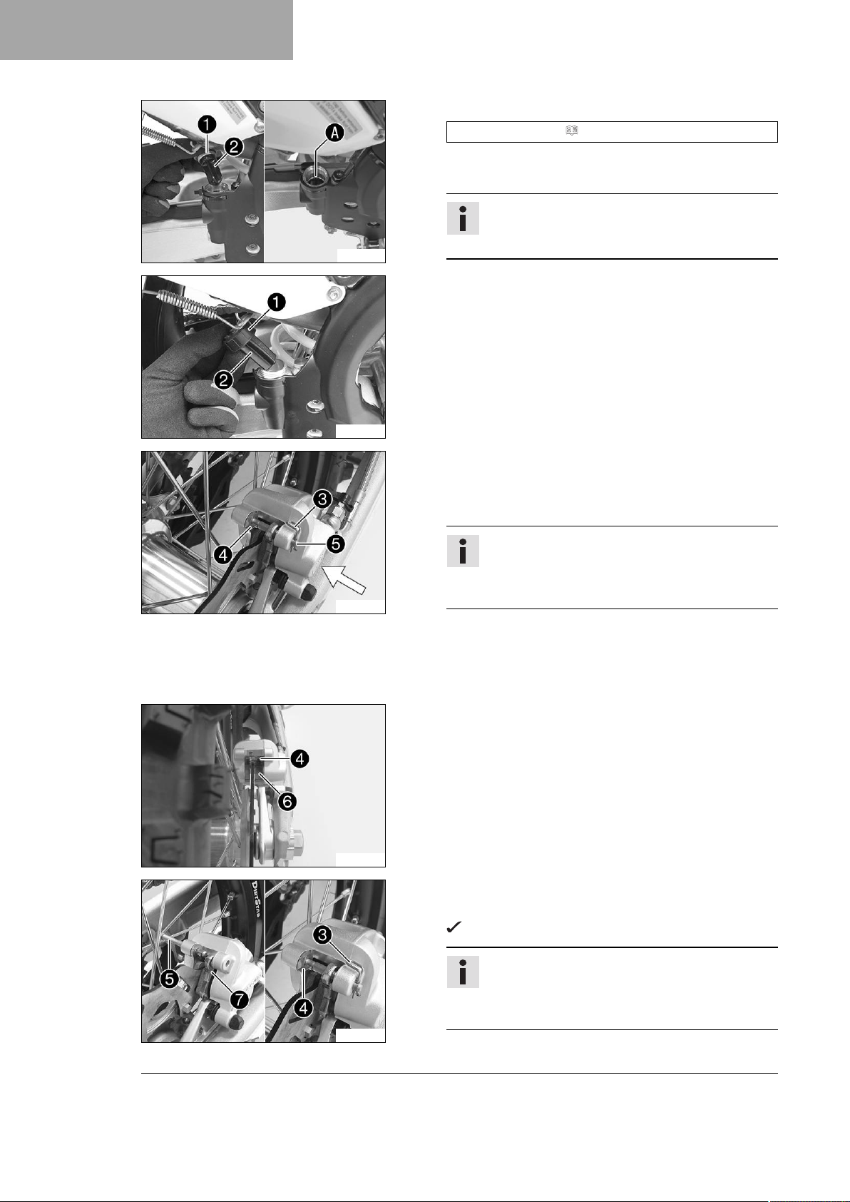
12 BRAKE SYSTEM
F00085-10
H02367-10
–
Add brake fluid to levelA.
Brake fluid DOT 4 ( p. 137)
–
Mount and tighten screw cap1with membrane2and
the O-ring.
Info
Clean up overflowed or spilled brake fluid immediately with water.
(Option: Magura)
– Stand the vehicle upright.
– Remove the cable ties on the frame protector.
–
Remove screw cap1with membrane2and the shim.
H02368-11
H02369-10
– Manually press the brake caliper to the brake disc to push
back the brake piston. Ensure that brake fluid does not
flow out of the brake fluid reservoir, extracting it by suction if it does.
Info
Make sure when pushing back the brake piston
that you do not press the brake caliper against the
spokes.
–
Remove cotter pin3.
–
Push leaf spring4downwards and remove pin5.
– Remove brake linings.
– Clean the brake caliper and brake caliper support.
–
Check that leaf spring4in the brake caliper and sliding
plate6in the brake caliper support are seated correctly.
92
H02370-10
– Insert the new brake linings.
–
Mount pin5.
Leaf spring4engages in the groove on the pin.
Info
Always change the brake linings in pairs.
Make sure that decoupling plate7is mounted
on the piston side brake lining.
–
Mount cotter pins3.

H02366-10
12 BRAKE SYSTEM
– Operate the foot brake lever repeatedly until the brake
linings are in contact with the brake disc and there is a
pressure point.
–
Add brake fluid to levelA.
Brake fluid DOT 4 ( p. 137)
–
Mount and tighten screw cap1with membrane2and
the shim.
Info
Clean up overflowed or spilled brake fluid immediately with water.
– Mount new cable ties on the frame protector.
93

13 WHEELS, TIRES
13.1 Removing the front wheel
Preparatory work
– Raise the motorcycle with a lift stand. ( p. 46)
Main work
(Option: Brembo)
– Press the brake caliper onto the brake disc by hand in
order to push back the brake pistons.
Info
Make sure that you do not press the brake caliper
against the spokes when pushing back the brake
pistons.
F00066-10
(Option: Magura)
– Press the brake caliper onto the brake disc by hand in
order to push back the brake pistons.
Info
Make sure that you do not press the brake caliper
against the spokes when pushing back the brake
pistons.
H02363-12
H02371-10
H02372-10
–
Loosen screw1by several rotations.
–
Loosen screws2.
–
Press on screw1to push the wheel spindle out of the axle
clamp.
–
Remove screw1.
Warning
Danger of accidents Damaged brake discs reduce
the braking effect.
– Always lay the wheel down in such a way that the
brake disc is not damaged.
– Holding the front wheel, withdraw the wheel spindle. Take the
front wheel out of the fork.
Info
Do not pull the hand brake lever when the front wheel
is removed.
94

–
Remove spacers3.
H00934-10
13.2 Installing the front wheel
Warning
Danger of accidents Oil or grease on the brake discs reduces the braking effect.
– Always keep the brake discs free of oil and grease.
– Clean the brake discs with brake cleaner when necessary.
– Check the wheel bearing for damage and wear.
» If the wheel bearing is damaged or worn:
– Change front wheel bearing.
–
Clean and grease shaft seal rings1and contact
surfacesAof the spacers.
13 WHEELS, TIRES
H00935-10
H02371-11
Long-life grease ( p. 139)
– Insert the spacers.
– Clean and grease the wheel spindle.
Long-life grease ( p. 139)
– Position the front wheel and insert the wheel spindle.
The brake linings are correctly positioned.
–
Mount and tighten screw2.
Guideline
Screw, front wheel
spindle
– Operate the hand brake lever several times until the brake
linings are seated correctly against the brake disc.
– Remove the motorcycle from the lift stand. ( p. 46)
– Operate the front brake and compress the fork a few times
firmly.
The fork legs straighten.
–
Tighten screws3.
Guideline
Screw, fork stub M8 15 Nm (11.1 lbf ft)
M20x1.5 35 Nm (25.8 lbf ft)
95

13 WHEELS, TIRES
13.3 Removing the rear wheel
Preparatory work
– Raise the motorcycle with a lift stand. ( p. 46)
Main work
(Option: Brembo)
– Press the brake caliper onto the brake disc by hand in
order to push back the brake piston.
Info
Make sure when pushing back the brake piston
that you do not press the brake caliper against the
spokes.
–
Remove nut1.
–
Remove chain adjuster2. Pull out wheel spindle3far
enough to allow the rear wheel to be pushed forward.
– Push the rear wheel forward as far as possible. Remove
the chain from the rear sprocket.
E00268-10
Info
Cover the components to protect them against
damage.
Warning
Danger of accidents Damaged brake discs
reduce the braking effect.
– Always lay the wheel down in such a way that
the brake disc is not damaged.
– Holding the rear wheel, withdraw the wheel spindle. Take
the rear wheel out of the swingarm.
Info
Do not operate the foot brake lever when the rear
wheel is removed.
96

H02374-10
13 WHEELS, TIRES
(Option: Magura)
– Press the brake caliper onto the brake disc by hand in
order to push back the brake piston.
Info
Make sure when pushing back the brake piston
that you do not press the brake caliper against the
spokes.
–
Remove nut1.
–
Remove chain adjuster2. Pull out wheel spindle3far
enough to allow the rear wheel to be pushed forward.
– Push the rear wheel forward as far as possible. Remove
the chain from the rear sprocket.
Info
Cover the components to protect them against
damage.
Warning
Danger of accidents Damaged brake discs
reduce the braking effect.
– Always lay the wheel down in such a way that
the brake disc is not damaged.
– Holding the rear wheel, withdraw the wheel spindle. Take
the rear wheel out of the swingarm.
Info
Do not operate the foot brake lever when the rear
wheel is removed.
–
Remove spacers4.
H00936-10
13.4 Installing the rear wheel
Warning
Danger of accidents Oil or grease on the brake discs reduces the braking effect.
– Always keep the brake discs free of oil and grease.
– Clean the brake discs with brake cleaner when necessary.
97

13 WHEELS, TIRES
Main work
– Check the wheel bearing for damage and wear.
» If the wheel bearing is damaged or worn:
– Change the rear wheel bearing.
–
Clean and grease shaft seal rings1and contact
surfacesAof the spacers.
Long-life grease ( p. 139)
H00937-10
H02375-10
– Insert the spacers.
– Clean and grease the wheel spindle.
Long-life grease ( p. 139)
–
Position the rear wheel and insert wheel spindle2.
The brake linings are correctly positioned.
– Mount the chain.
–
Position chain adjuster3. Mount nut4, but do not tighten
it yet.
–
Make sure that chain adjusters3are fitted correctly on
adjusting screws5.
– Check the chain tension. ( p. 69)
–
Tighten nut4.
Guideline
Nut, rear wheel spindle
M25x1.5 80 Nm (59 lbf ft)
Info
The wide adjustment range of the chain adjusters
(32 mm (1.26 in)) enables different secondary ratios
with the same chain length.
Chain adjusters3can be turned by 180°.
98
H02376-10
– Operate the foot brake lever repeatedly until the brake lin-
ings are in contact with the brake disc and there is a pressure
point.
Finishing work
– Remove the motorcycle from the lift stand. ( p. 46)
 Loading...