

Page 1
EN
Operator´s manual p. 3
Please read the operator’s manual carefully and make sure you
understand the instructions before using the machine.
DE
NL
IT
Bedienungsanweisung p. 19
Lesen Sie die Bedienungsanweisung sorgfältig durch und machen Sie
sich mit dem Inhalt vertraut, bevor Sie das Gerät benutzen.
Gebruiksaanwijzing p. 35
Neem de gebruiksaanwijzing grondig door en gebruik de machine
niet voor u alles duidelijk heeft begrepen.
Istruzioni per l’uso p. 51
Prima di usare la macchina, leggere per intero le istruzioni per l’uso
e accertarsi di averne compreso il contenuto.
CS 2512
EN DE NL IT
HUSQVARNA CONSTRUCTION PRODUCTS
Page 2

Page 3

5
6
7
8
10
11
12
12
13
14
14
14
15
15
Operator's Manual CS 2512
Contents
English
Contents
Key to symbols
Safety Instructions
Introduction
What is what
Technical data
Assembling/Installing equipment
Connection to the hydraulic unit
Threading the wire
Placement of the cooling water
Operation
Sawing
........................................................................
...............................................................................
Finishing sawing
..............................................................
......................................................
......................................................................
....................................................................
.............................................................
...........................
.......................................................
.............................
...........................................................
...................
Cleaning
Maintenance
............................................................................
...................................................................
EU declaration of conformity
.............................
English - 3
17
Page 4

4
Contents
Operator's Manual CS 2512
- English
Page 5
Pr
W
CE
Operator's Manual CS 2512
Key to symbols
The symbols belo w are used on the machine and in this
Operator's Manual. It is important that the user
understands the significance of these in order to work with
the machine safely.
Man ual
Please read the Oper ator's Manual carefully and
understand the contents before the machine is started.
otective equipment
Alw ays wear:
• Approved protective helmet.
• Approved hearing protection.
Key to symbols
Remark
A hand with a r aised index finger with the text “Attention”
signifies that a described element demands extra
attention.
This symbol indicates that the machine conf orms to
applicable EU directives.
• Approved protective glasses or a visor, and other
essential safety equipment.
arning
A large w arning triangle with the text “Warning” signifies
that there is a risk of serious personal injury or even
death.
Caution
A smaller w arning triangle with the text “Note” signifies
that there is a risk of minor personal injury or damage to
the machine.
English -
5
Page 6

6
W
Sw
y
Safety Instructions
Safety Instructions
Dur ing the design and production of Husqvarna products,
great importance is placed on safety, as well as effectiveness and ease of use. To ensure that the machine remains
safe you must pay attention to the following points:
ARNING!
This mac hine is onl y intended f or use
tog ether with a Husqv arna PP 455E or a
unit connected to Husqv arna RC 455. All
other use is f orbid den.
CAUTION
Under no circumstances ma y the machine be
star ted without obser ving the saf ety
instr uctions . Should the user f ail to comply
with these , Husqv ar na Constr uction Products
eden AB or its representativ es are free
from all liability both directly and indirectly .
Read through these oper ating instr uctions and
mak e sure that y ou understand the contents
bef ore star ting to use the machine . Should
ou, after reading these saf ety instr uctions,
still feel uncertain about the safety risks
involved you must not use the machine Please
contact your dealer for more information.
Operator's Manual CS 2512
• Do not misuse hoses.
• Do not use hoses that are distorted, worn, or
damaged.
• Check that the hoses are connected correctly to the
machine and that the hydraulic couplings lock as
intended before pressurising the hydraulic system. The
couplings are locked by turning the outer sleeve on the
female coupling so that the slot moves away from the
ball.
• Keep the hydraulic hoses and couplings free from dirt.
• Always switch off the power to the hydraulic unit before
moving equipment.
• Always saw in a manner that permits easy access to
the emergency stop.
• Never leave the machine unsupervised with the motor
running.
• Clearly mark out all cuts to be made before you start
sawing, plan these so they can be carried out without
danger to persons or the machine.
• Check with building drawings whether electrical cables,
water pipes, gas pipes or sewage pipes have been
routed within the working area.
• Always check and mark out where gas pipes are
routed. Cutting close to gas pipes always entails
danger. Make sure that sparks are not caused when
cutting in view of the risk of explosion. Remain
concentrated and focused on the task. Carelessness
can result in serious personal injury or death.
• Check that all couplings, connections and hydraulic
hoses are in full working order.
• Make sure that all hoses are connected to the machine
correctly before you start the machine.
• Make sure that there are no persons or animals in the
working area.
• Check that the guard is not broken and that it is fitted
correctly.
• Never cut without using the guard.
• Never disconnect the hydraulic hoses without first
shutting off the hydraulic unit and ensuring the motor
has stopped completely.
• Check the machine, couplings and hydraulic hoses
daily for leakage. A rupture or leak can cause a
”hydraulic fluid injection” in the body or result in other
serious physical injury.
• Do not exceed the specified hydraulic fluid flow or
pressure for the tool being used. Too high pressure can
result in rupturing.
• Check that electrical cables within the working area are
not live.
• Hoses that are marked and approved as electrically
non conductive must be used when using hydraulic
tools on or in the vicinity of electrical cables. The use of
other types of hoses can result in serious physical
injury or even death.
• Observe care when lifting. You are handling heavy
parts, which implies the risk of pinch injuries or other
injuries.
• Personal protective equipment and protective clothing
as set out in the Operator's manual must always be
worn. Never wear loose fitting clothes that can catch in
moving parts.
• Only use wire recommended by the manufacturer.
• Never cut without using the cooling water. A poorly
cooled wire can result in the segments overheating,
which results in greater wear. In the worst case
scenario, segments can come loose from the wire and
injure persons close to the saw.
- English
Page 7
Introduction
Husqvarna CS 2512 is designed for use together with the
hydraulic unit PP 455 E or Husqvarna RC 455. Husqvarna
CS 2512 is a powerful and easy to use wire saw with a
capacity for really large work, yet at the same time
sufficiently compact and mobile for small work. It can be
used in many different ways, both on the ground and fitted
to the wall.
The well thought-out design of the CS 2512, where the
drive wheel is placed on the machine's output side means
that the wire is always under tension even when the feed
force is low. Combined with the adjustable pressure valve
this gives exact control of cutting and unbeatable
performance.
The machine can be rigged both vertically and horizontally
and many cuts can be made directly without external idler
wheels.
Complete saw equipment consists of:
IntroductionOperator's Manual CS 2512
1 x saw unit
1 x accessory box
1 x 18 mm wrench
1 x pressure reduction block
1 x extra wear rubber for the magazine wheel
1 x cleaning brush
English - 7
Page 8
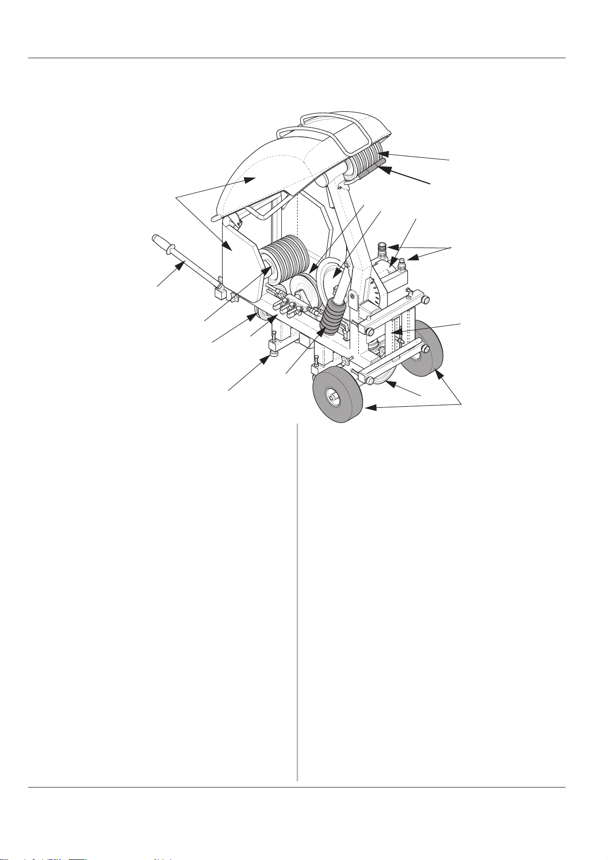
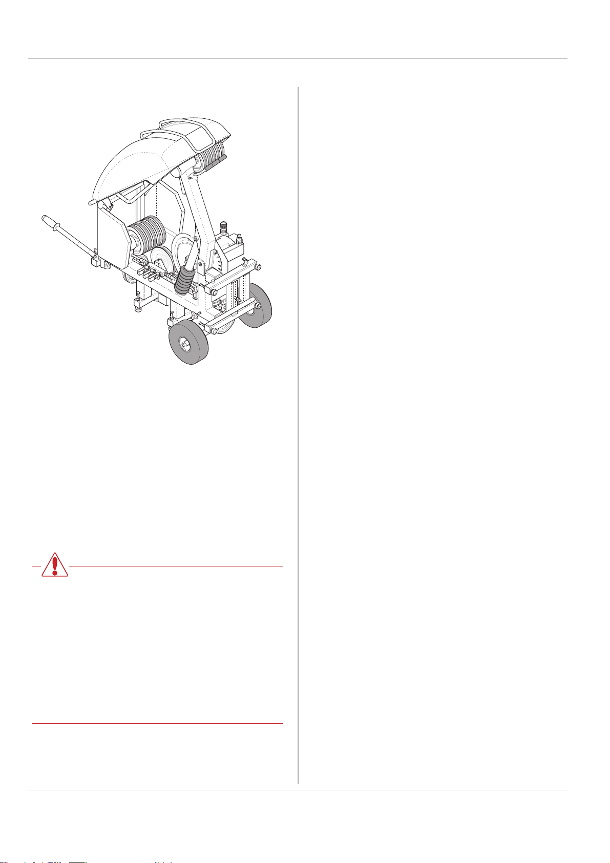
What is what Operator's Manual CS 2512
What is what
4
6
7
4
14
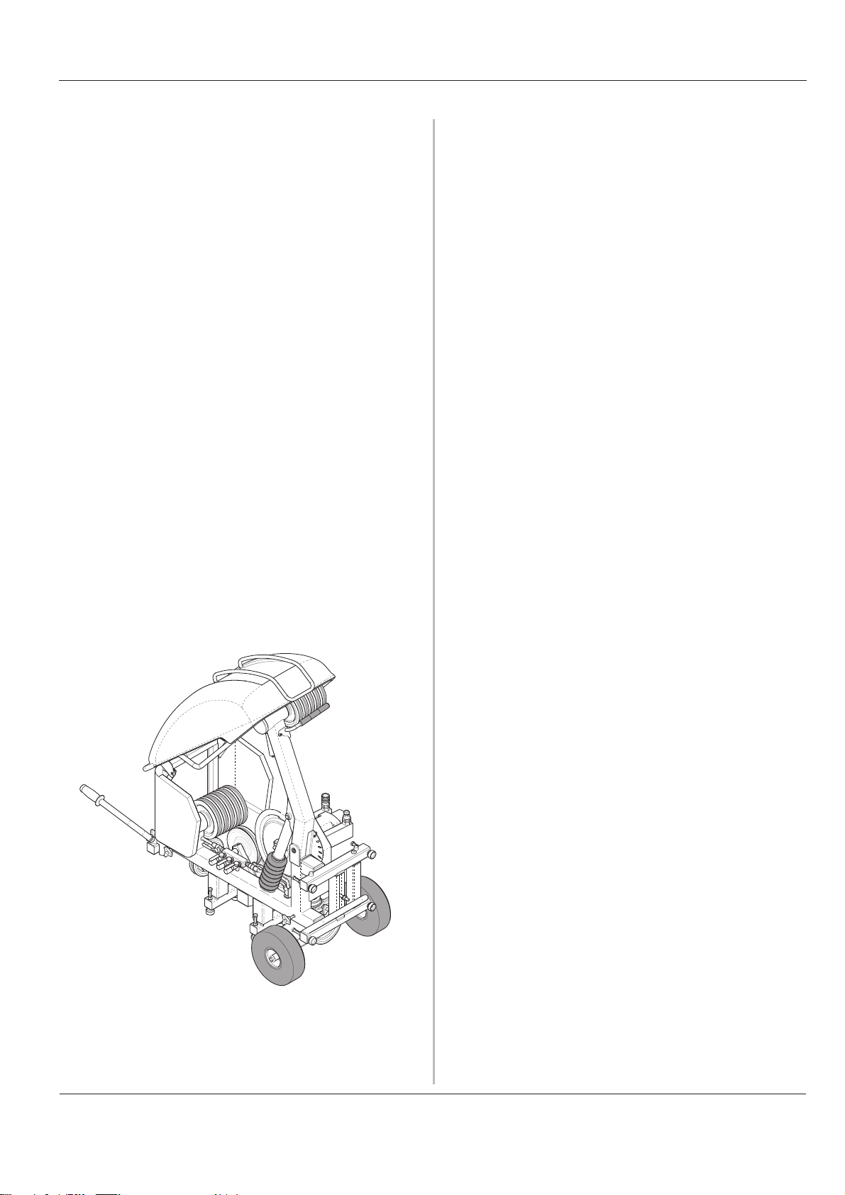
The saw consists of the following component parts:
1. Hydraulic motor
The machine is powered by a 60 cubic centimetre
motor. The motor has two parts, one of 50 cubic
centimetres and a smaller part of 10. Two gears are
obtained by using either just the large motor or both
the large and small motors together. The two gears
give different speeds, yet the same power.
2. Hydraulic hose connections
9
8
5
4. Wire magazine
Tensions the wire and stores recovered wire. The wire
magazine has a capacity to store a maximum of 12
metres of wire (2.4 metres per wheel set).
5. Magazine cylinder
The magazine cylinder tensions the wire in the
magazine and with that governs cutting. The pressure
in the cylinder is adjusted by means of the pressure
reduction block fitted on PP 455E or RC 455.
15
11
3
1
2
12
14
10
The hydraulic flow in the two large hoses drives the
machine's motor and with that the wire. The flow in the
two smaller hoses drives the magazine cylinder.
3. Drive wheel
Transfers the motive force from the motor to the wire.
The drive wheel is 400 mm in diameter and is covered
with replaceable rubber to give as good grip as
possible between the drive wheel and wire.
The drive wheel forms together with the hydraulic
motor and the hydraulic connections the drive wheel
unit. The drive wheel unit is adjusted depending on
how many wheel sets are used in the magazine. These
can easily be dismantled to give a lighter machine
during transporting.
8 - English
6. Guard
The machine has a two-piece guard. A fixed part made
of sheet metal and a folding cover made of plastic and
metal. The guard is easy to remove, e.g. when the wire
is threaded, it should always be fitted in position when
cutting.
7. Lifting handle
The folding handle is the perfect aid when transporting
the machine.
8. Adjustable feet
Adjusted so the saw stands firmly. In total, the saw
features 10 feet, six for horizontal cutting and four for
the vertical position.
Page 9
What is whatOperator's Manual CS 2512
9. Cooling water connections
There are two connections on the machine for water
spears and one for the incoming water. Besides
cooling the wire with these, the wire is also rinsed
when it returns to the machine and when it leaves the
machine by small nozzles.
10.Rubber wheels
To facilitate transport. The wheels can be dismantled in
some situations to facilitate access on certain jobs.
This is done by removing the split pins that lock the
wheels on the wheel axle.
11.Wire boom
Holds the wire in against the magazine when the magazine is run in. This prevents the wire tangling when
not tensioned, e.g. when changing the wire or when
changing the number of wheels used in the magazine.
12.Anchor beam
Adjustable beam with a longitudinal slot. By moving
this beam sideways, you can position the anchor bolt in
a suitable position without the need of moving the
entire saw when anchoring the saw before cutting.
Accessories
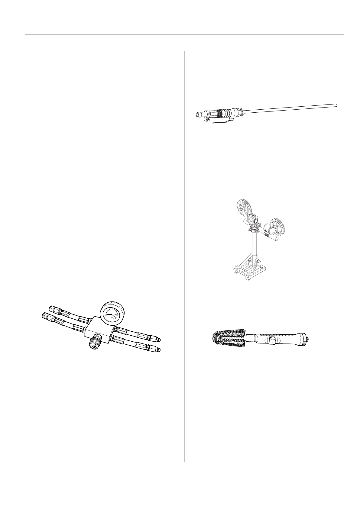
1. Water spear
Connected to the water connections on the saw and
used to guide cooling water into the cut to cool the wire
and to bind the concrete dust.
2. Idler wheels
Husqvarna idler wheels are designed to smoothly
guide the wire as efficiently as possible. By using idler
wheels the number of sharp corners to cut around can
be reduced, which means that more of the cutting
capacity is used for material removal.
An additional anchor beam is placed under the saw.
The anchor bolt is secured in this beam when
horizontal cutting.
13.Pressure reduction block
The pressure reduction block is fitted between the
hydraulic unit and the hydraulic hoses for the input supply. There is a valve located on the pressure reduction
block, this is used to control the magazine tension.
14.Swivel wheels
The swivel wheels supported on bearings are located
where the wire enters the saw and out through the
saw. The swivel wheels help to guide the wire so it is
positioned correctly in the saw and can either be
locked in a fixed position or used in the unlock position
so that the wheels follow the wire.
3. Cleaning brush
Can be connected to the water hose and then used to
clean the machine after use.
15.Guide wheel
Guides the wire from the magazine to the drive wheel.
When the drive wheel unit is adjusted, the guide wheel
is set automatically depending on the number of
magazine wheels used.
English - 9
Page 10
Technical data Operator's Manual CS 2512
Technical data
Power on drive wheel (with PP 455): ____ 20 kW
Hydraulic oil flow: ___________________ 65l/min (17 gal/min)
Max permitted hydraulic pressure ______ 230 bar (3400 psi)
Max recommended hydraulic
pressure
Maximal wire length in the magazine: ___ 12 m
Dimensions, handle folded in and
the
Weight:___________________________ 150 kg ( 330lbs)
Wire speed gear 1 __________________ 20 m/s (66 ft/s)
Wire speed gear 2 __________________ 25 m/s (82 ft/s)
when cutting:_______________ 130 bar (1900 psi)
(2.4 m/wheel set)
guard folded down (L x W x H) ______ 1150x750x980 mm
Recommended wires:
Husqvarna recommends that the following wires are used:
• Husqvarna C710C
Husqvarna C710C is a galvanised wire developed for
use when cutting concrete with a great deal of
reinforcement. The segments have a great number of
diamonds and a smaller diameter (9.5mm) which
means the wire cuts very efficiently. The smaller
diameter also means that C710C can be used to finish
difficult cuts.
• Husqvarna C750C
Husqvarna C750C is an all round wire developed for
use when cutting reinforced concrete. The wire has
been designed for use with saws with an output power
between 10 and 25 kW.
• Husqvarna C760C
This is the Husqvarna premium wire: long life, high
cutting rate and high power resistance characterize
this wire. Husqvarna C760C can be used to cut all
types of reinforced concrete, even when the work
places high demands on the wire, for example when
cutting bridges.
• Husqvarna C790C
The segment strength on this wire makes Husqvarna
C790C the best choice when cutting soft materials
such as mortar, and lightly reinforced limestone
concrete.
• Husqvarna C575J
Husqvarna C575J is a wire with galvanised 15 mm
segments.
Husqvarna C1200M
HusqvarnaC1200M is a wire developed for use when
cutting steel. The wire has been designed for use in
WARNING
Under no circumstances may
modifications be made to the machine
without written permission from
Husqvarna Construction Products Sweden
AB. Non approved modifications put you
extremely demanding situations. The use of the latest
sintering technique has given enormous advantages
with regard to cutting rates and life span. The wire can
be supplied with either joined or loose ends.
For further information about different tools from
Husqvarna, contact your Husqvarna dealer.
and others at risk of serious or fatal
injuries. Husqvarna Construction Products
Sweden AB bears no responsibility for
operations that do not conform to these
instructions.
10 - English
Page 11

Operator's Manual CS 2512
English - 11
Page 12
Assembling/Installing equipment Operator's Manual CS 2512
Assembling/Installing
equipment
Cutting needs to be planned carefully before assembling
the saw so that it can be performed as easily as possible.
Husqvarna CS 2512 can be assembled to make either
horizontal or vertical cuts. The saw is assembled standing
when you wish to make vertical cuts.
The saw is assembled horizontally when the cut is to be
made at floor height and when the cut is made in the floor.
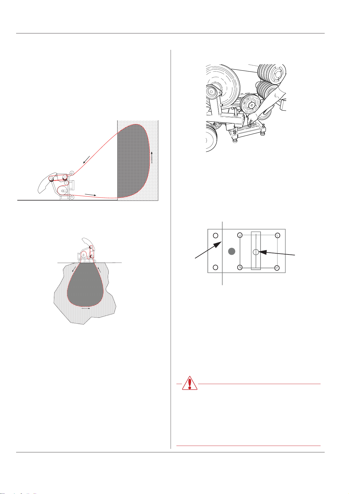
When the saw is anchored to the floor, screw down the
adjuster feet so that the saw stands firmly.
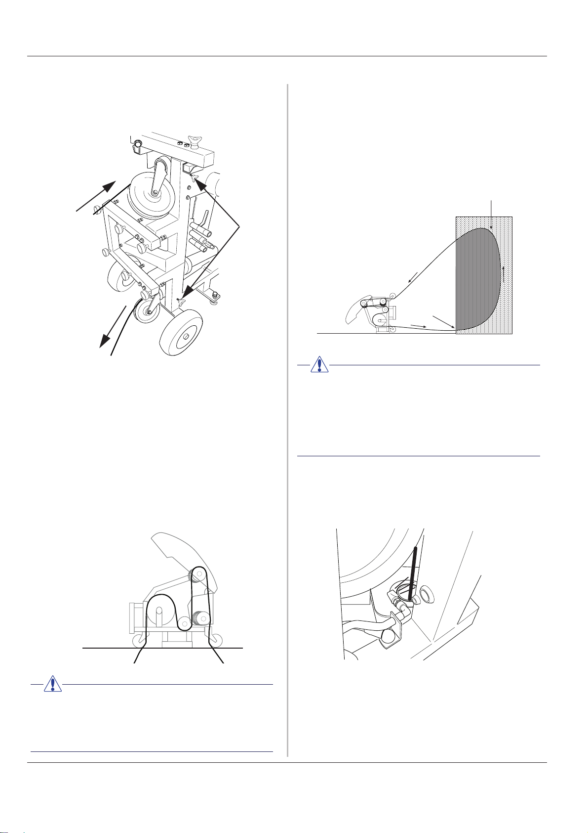
Remember that the machine's centre of gravity (the grey
circle) is positioned between the first and second pairs of
adjuster feet (the adjuster feet pairs are marked 1-3) with a
horizontal cut (A). When cutting under the machine, it is
important that the saw is anchored well with the anchor
bolt (b) as the adjuster feet pairs 2 and 3 must be used.
(Adjuster feet pair 1 may rest on the sawn off section.) If
the saw is not anchored well it will overturn when the material supporting adjuster feet pair 1 has been cut through.
It may be necessary to drill holes to thread the wire
through the material to be cut.
Position the saw in an appropriate position in front of the
planned cut. When the saw is in position, secure it by
screwing down the anchor bolt.
A
1
If necessary, fit idler wheels to assist the cutting process.
Using the idler wheels allows the number of sharp corners
that the wire must be pulled around can be reduced,
which results in less wear to the wire at the same time as
cutting is made easier. Using the idler wheels also lets the
wire be guided in different directions without the need of
moving the saw unit.
Also, use the idler wheels to capture the wire when
finishing the cut.
WARNING!
Always position the saw so that you can
stand without the risk of being hit by a
broken wire. Ensure that no unauthorised
persons can access the working area while
cutting. Being hit by a broken wire can
result in death or serious personal injury.
2
3
B
12 - English
Page 13
Assembling/Installing equipmentOperator's Manual CS 2512
Connection to the hydraulic unit
When the saw is assembled appropriately, it should be
connected to a hydraulic unit. Husqvarna CS 2512 is
designed for use with Husqvarna PP 455 or Husqvarna
RC 455.
1. Check that the hydraulic unit is connected to the power.
2. Connect the cooling water to the motor on the
hydraulic unit.
3. Check that the display on the remote control shows
“CONNECT HOSE BUNDLE”. If not follow the instructions in the Operator's manuals for PP 455E or RC 455.
4. Fit the two large hydraulic hoses on the unit first and
then to the saw motor connections. Lock the couplings
by turning the sleeve on the coupling so that the slot
moves away from the ball.
5. Fit the pressure reduction block on the hydraulic unit as
set out in the instructions on the block.
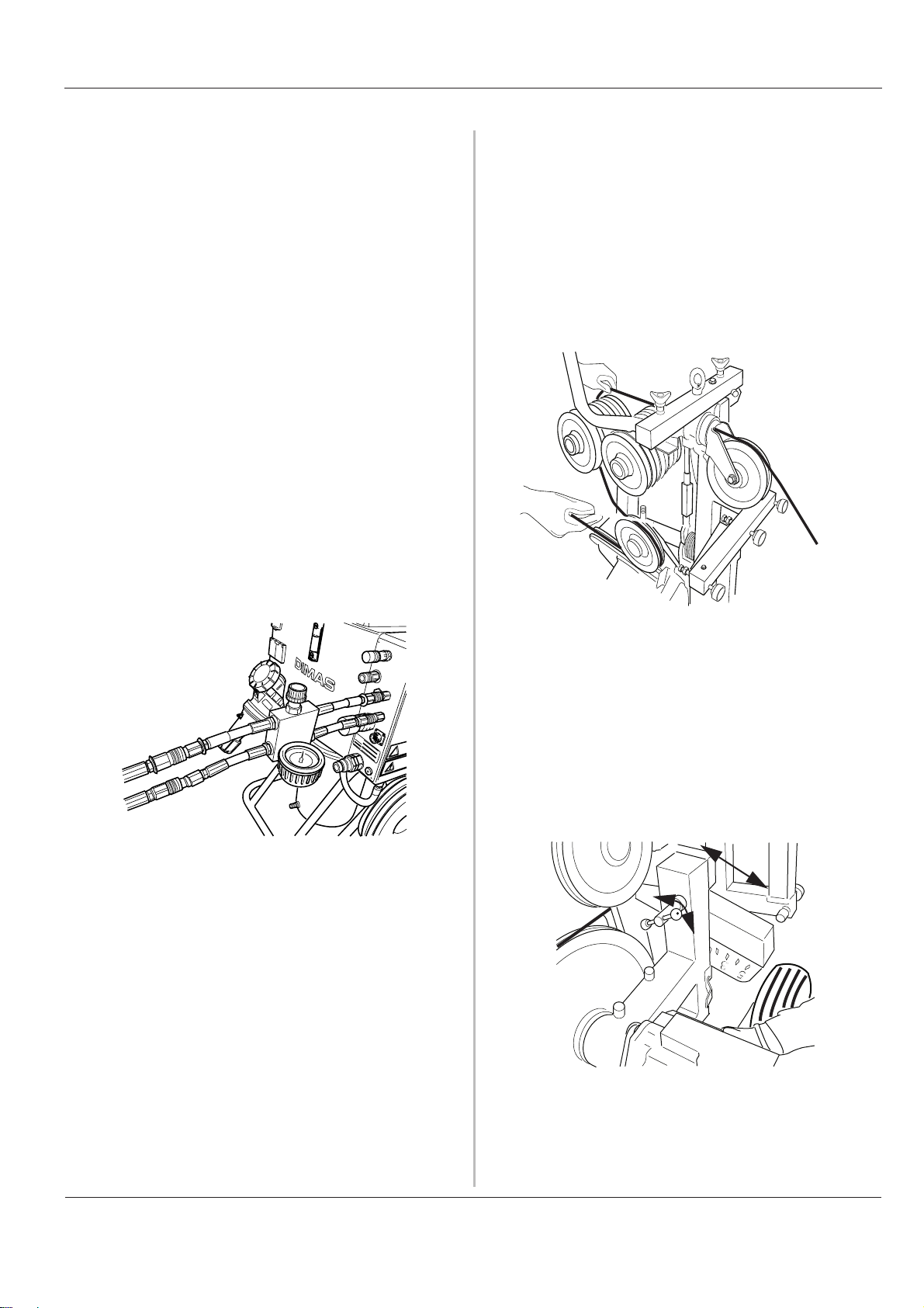
6. Connect the two smaller hydraulic hoses to the
pressure reduction block. The hoses in the hose
bundle marked with a red disc by the coupling shall be
connected to the hose on the pressure reduction block
that is also fitted with a disc.
Threading the wire
The guard can easily be lifted off to facilitate fitting wire.
Now thread the wire as follows:
1. Make sure the magazine is in the min position.
2. Place the wire around the work piece, possibly through
the predrilled holes and back to the saw.
3. Thread the wire through the hole by the swivel wheel
and around a suitable number of wheel sets in the
magazine.
Lock the couplings by turning the sleeve on the
coupling so that the slot moves away from the ball.
7. Fit the two hoses connected on the pressure reduction
block to the hoses to the feed cylinder on the saw. The
hoses in the hose bundle marked with a red disc by the
coupling shall be connected to the hose on the saw
that is also fitted with a disc.
8. Connect the water hose to the incoming water on the
saw.
If the couplings jam when assembling, they should be
removed completely before being refitted.
4. Adjust the drive wheel unit according to the number of
wheel sets used in the magazine:
Loosen the arm by screwing out the knob anticlockwise. Now turn the drive wheel unit so that the
arm is aligned with the markings on the saw. Lock the
drive wheel unit by turning back the knob.
Usually only one wheel set is used in the first stage of
cutting.
Make sure that the couplings on the hoses not in use do
not lie directly on the ground.
Always keep the couplings as clean as possible. A clean
coupling lasts longer.
English - 13
Page 14
Assembling/Installing equipment Operator's Manual CS 2512
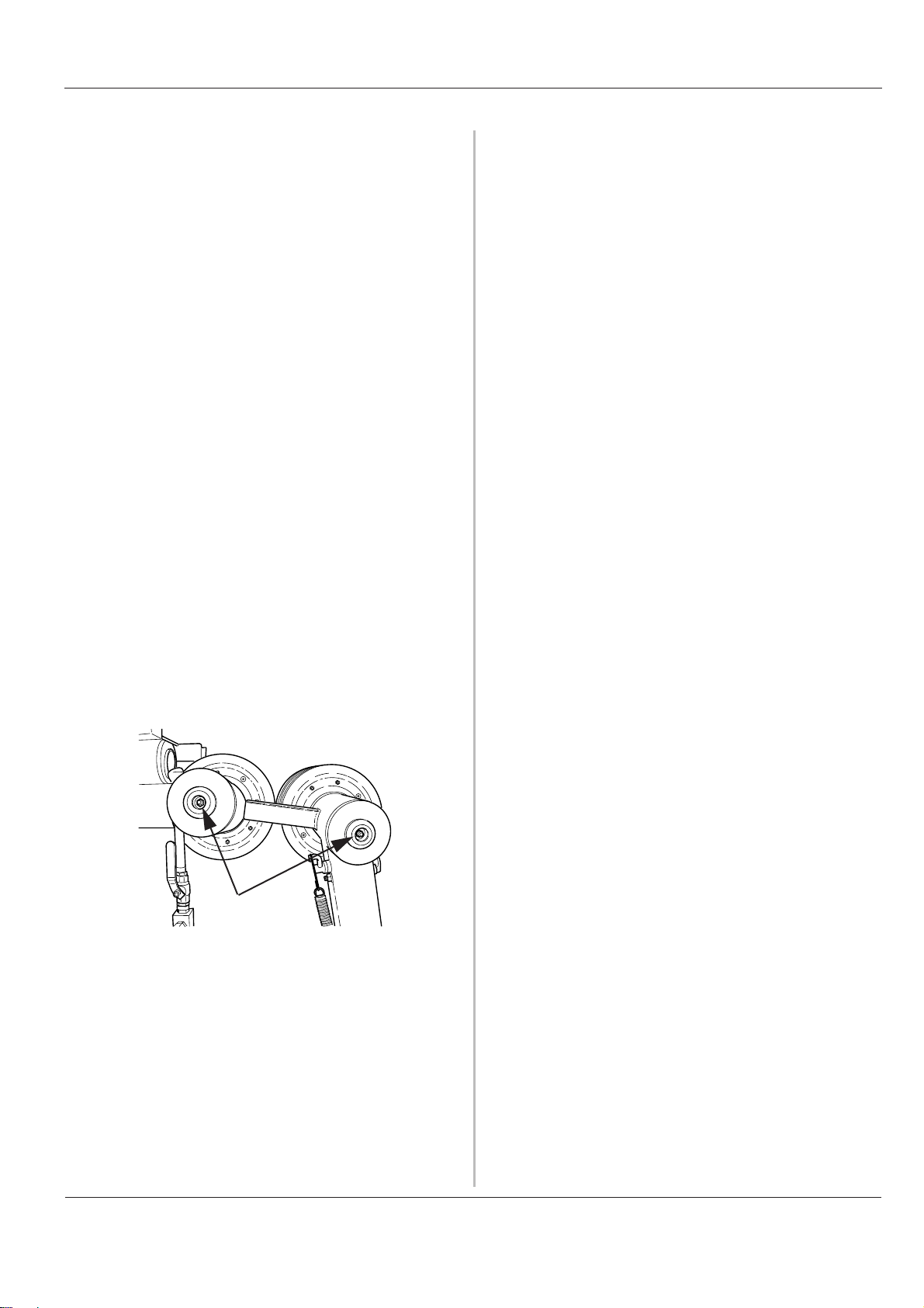
5. Thread the wire around the drive wheel and out
through the hole by the second swivel wheel. The
swivel wheel can rotate and be locked in the required
position by turning the marked (A) knobs.
a
6. Before the joints on the wire are connected, the wire
should be twisted 1 to 2 turns per metre wire used. It is
important to twist the wire in the same direction as it is
spun. This is to give as even wear as possible on the
wire’s diamond segments.
7. Lock the wire with a pin. If there are no end sleeves on
the wire, these must be spliced on to the wire. A
special pair of wire pliers must be used. If you are
unsure about which model you should use, contact
your DIMAS dealer.
8. When the wire is routed correctly it should run through
the machine as in the figure below:
Placement of the cooling water
Husqvarna CS 2512 is equipped with two outlets for the
cooling water. Ideally, Husqvarna water spears can be
connected to these. The water spears are then placed
where the wire enters the concrete. In this way the wire
takes water with it into the cut, which results in the
concrete dust binding and that the wire is cooled
efficiently.
WATER
WATER
CAUTION
In order for the water to cool the wire as
intended during cutting, it is essential to adjust
the position of the cooling water as the
material is cut. Remember to always stop the
machine when you do this.
In addition to the cooling water from the water spear, the
wire is rinsed by the two swivel wheels on the machine.
This is to keep the wire as clean as possible, which means
that the saw can work with less friction losses and greater
efficiency as the wire becomes cleaner.
CAUTION
A used wire must always be run in the same
direction, as it was previously run in order to
prevent unnecessary wear.
14 - English
Page 15

Assembling/Installing equipmentOperator's Manual CS 2512
English - 15
Page 16
Operation Operator's Manual CS 2512
Operation
Sawing
When all the equipment has been assembled cutting can
start. In order for the saw to cut as efficiently as possible it
should be started as follows:
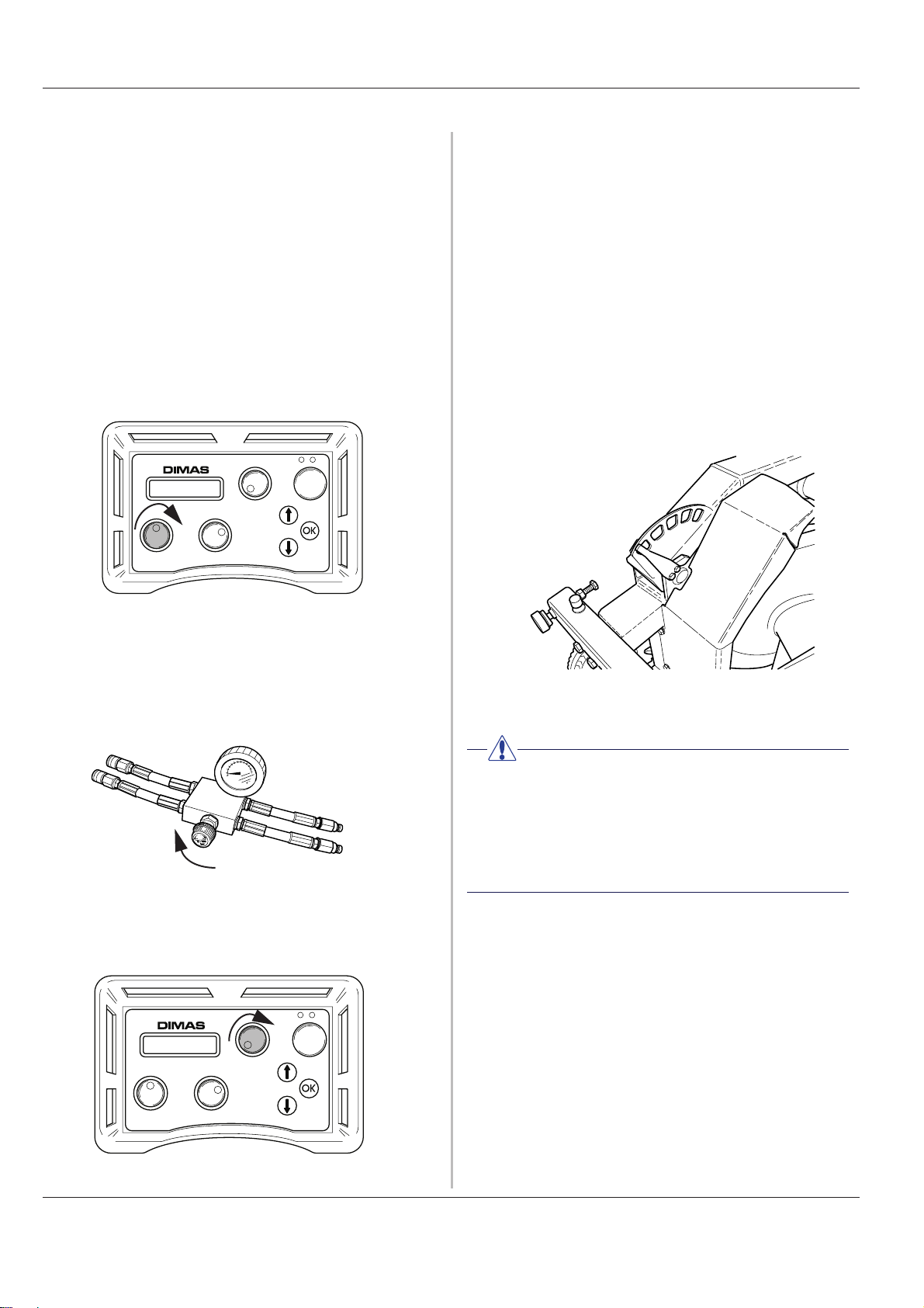
1. Close the valve on the pressure reduction block by
turning the knob anti-clockwise until it stops and then
two turns back.
2. Start the hydraulic unit.
3. Set the feeding flow on the unit to max by turning the
control on the remote control clockwise.
6. Carefully increase the motor speed by turning the
control for motor rotation. A suitable working pressure
when cutting usually lies between 100 and 130 bar, but
varies depending on how many wheel sets are used in
the magazine, how much wire is in use and the
hardness of the material to be cut.
7. As the material is cut away the working pressure
drops, which is shown on the display, and the
magazine must then be tensioned. Do this by turning
the knob on the pressure reduction block clockwise.
8. The output tension on the magazine is shown by an
indicator on the machine (shown in the min position).
When the magazine cylinder is fully tensioned, the
machine must be stopped and the wire must be wound
around a new wheel set. Then continue to cut as
above.
4. Tension the wire by carefully turning the knob on the
pressure reduction block clockwise until the wire is
tensioned sufficiently. Make sure to always check that
the wire is seated correctly in all the wheels on the
saw.
5. Start the motor's rotation by turning the control for
motor rotation on the remote control clockwise.
CAUTION
In order for the water to cool the wire as
intended during cutting, it is essential to adjust
the position of the cooling water as the
material is cut. Remember to always stop the
machine when you do this.
Finishing sawing
1. Lower the speed on the wire and allow the motor to
stop completely.
2. Fold up the magazine arm.
3. Disconnect the incoming mains cable from the
hydraulic unit.
4. Disconnect the hydraulic hoses and the water hose
from the saw unit.
5. Other steps are done in the reverse order.
14 - English
Page 17
Cleaning
The saw should be cleaned once cutting is finished. It is
important to clean all the saw equipment. It is a good idea
to disconnect the water hose from the pivot arm and use
this to wash down the saw unit. If necessary, you can also
use the supplied cleaning brush or the like to clean the
equipment. Do not use a high pressure washer to clean
the saw.
Maintenance
In addition to the daily maintenance such as cleaning and
lubrication, the machine must be serviced. After 50 hours
of cutting, the machine should be serviced at an
accredited Husqvarna workshop. The saw should then be
serviced after every 100 hours of operation. The service is
important so that as the user you have a machine that
works as effectively as possible for a long time.
OperationOperator's Manual CS 2512
Lubrication
In order for the wire to run as friction free as possible, the
magazine axles must be filled with grease. Fill with grease
after every 5 -10 hours of operation. Use Canadian
Petroleum OG2 or similar grease.
The bearings on the magazine axles also need to be
lubricated regularly, but not as often as the magazine
axles.
English - 15
Page 18

Operation Operator's Manual CS 2512
16 - English
Page 19

EU declaration of conformityOperator's Manual CS 2512
EU declaration of conformity
Husqvarna Construction Products Sweden AB, Box 2098, 550 02 Jönköping, Sweden, tel:
036-570 60 00, hereby declares that the wire saw CS 2512, from serial number 01001
onwards, is manufactured in compliance with the Council's machinery directive 98/37/EC,
low-voltage directive 73/23/EEC and EMC directive 89/336/EEC, including subsequent
amendments, and that the following standards have been used for guidance: EN 55 014-1,
EN 55 014-2, EN 61 000-3-2, EN 50 144-1, EN 13 862.
Jönköping 2005-01-01
Christer Carlberg
Managing Director
English - 67
Page 20

EU declaration of conformity Operator's Manual CS 2512
68 - English
Page 21

Bedienungsanleitung CS 2512
Inhalt
Deutsch
Inhalt
Symbolerklärung ....................................................... 21
Sicherheitsvorschriften......................................... 22
Einleitung ....................................................................... 23
Komponentenerklärung ........................................ 24
Technische Daten ..................................................... 26
Ausrüstung montieren/installieren ................ 27
An Hydraulikaggregat anschließen..................... 28
Seil einlegen................................................................... 28
Kühlwasserpositionierung........................................ 29
Bedienung...................................................................... 30
Sägen................................................................................. 30
Schneidvorgang beenden........................................ 30
Reinigung......................................................................... 31
Wartung ............................................................................ 31
Konformitätserklärung........................................... 33
Deutsch - 19
Page 22

Inhalt Bedienungsanleitung CS 2512
20 - Deutsch
Page 23

SymbolerklärungBedienungsanleitung CS 2512
Symbolerklärung
Diese Symbole sind auf der Maschine und in der
Bedienungsanleitung angegeben. Um sicher mit der
Maschine arbeiten zu können, muss der Bediener ihre
Bedeutung verstehen.
Anleitung
Lesen Sie vor der Inbetriebnahme der Maschine die
Bedienungsanleitung aufmerksam durch und machen Sie
sich mit dem Inhalt vertraut.
Schutzausrüstung
Verwenden Sie stets:
• einen zugelassenen Schutzhelm,
• einen zugelassenen Gehörschutz,
• eine zugelassene Schutzbrille oder einen
Gesichtsschutz sowie sonstige erforderliche
Schutzausrüstung.
Bemerkung
Eine Hand mit erhobenem Zeigefinger mit dem Zusatz
„Anmerkung“ bedeutet, dass ein beschriebener Vorgang
zusätzliche Aufmerksamkeit erfordert.
CE
Dieses Symbol weist darauf hin, dass die Maschine den
geltenden EU-Richtlinien entspricht.
Warnung
Ein großes Warndreieck mit dem Zusatz „Warnung“
bedeutet, dass die Gefahr von schweren, sogar
lebensgefährlichen Verletzungen besteht.
Achtung
Ein kleines Warndreieck mit dem Zusatz „Achtung“
bedeutet, dass die Gefahr von leichteren Verletzungen
oder Maschinenschäden besteht.
Deutsch - 21
Page 24

Sicherheitsvorschriften Bedienungsanleitung CS 2512
Sicherheitsvorschriften
Bei der Konstruktion und Herstellung von HusqvarnaProdukten wurde neben der Leistungsfähigkeit und
Benutzerfreundlichkeit größtes Gewicht auf die Sicherheit
gelegt. Folgende Punkte sind zu beachten, um einen
sicheren Maschinenbetrieb zu gewährleisten:
WARNUNG!
Diese Maschine darf nur zusammen mit
Husqvarna PP 455E oder einem Aggregat
genutzt werden, das an Husqvarna RC 455
angeschlossen ist. Jegliche andere
Verwendung ist unzulässig.
ACHTUNG
Die Maschine darf ausschließlich unter Befolgung der Sicherheitsvorschriften gestartet
werden. Bei Missachtung der Vorschriften seitens des Bedieners haftet Husqvarna Construction Products Sweden AB oder ihre
Vertreter weder direkt noch indirekt. Lesen Sie
die Bedienungsanleitung aufmerksam durch
und machen Sie sich mit dem Inhalt vertraut,
bevor Sie die Maschine benutzen. Sollten Sie
sich auch nach Lektüre der Sicherheitsvorschriften nicht über die vorliegenden Sicherheitsrisiken im Klaren sein, dürfen Sie die
Maschine nicht benutzen. Ihr Fachhändler
erteilt auf Anfrage gern weitere Informationen.
• Stellen Sie sicher, dass alle Verbindungen, Anschlüsse
und Hydraulikschläuche unbeschädigt sind.
• Kontrollieren Sie vor der Inbetriebnahme, ob alle
Schläuche korrekt an der Maschine angeschlossen sind.
• Vergewissern Sie sich, dass sich im Arbeitsbereich
keine Personen oder Tiere aufhalten.
• Überprüfen Sie, ob alle Schutzvorrichtungen
unbeschädigt und korrekt montiert sind.
• Schneiden Sie niemals ohne Schutzvorrichtungen.
• Hydraulikschläuche dürfen erst abgenommen werden,
nachdem das Hydraulikaggregat abgeschaltet wurde
und der Motor zum Stillstand gekommen ist.
• Überprüfen Sie täglich die Maschine sowie alle
Verbindungen und Hydraulikschläuche auf
Undichtigkeiten. Lecks oder ein Bersten von
Schläuchen können zu einem Eindringen von Öl in den
Körper oder zu anderen schweren Verletzungen führen.
• Die für das jeweilige Werkzeug angegebenen Werte
für den Öldurchfluss oder Öldruck dürfen nicht
überschritten werden. Ein zu hoher Druck kann zu
einem Bersten der Schläuche führen.
• Achten Sie stets auf die Unversehrtheit der
verwendeten Schläuche.
• Benutzen Sie keine deformierten, verschlissenen oder
beschädigten Schläuche.
• Stellen Sie sicher, dass die Schläuche korrekt an die
Maschine angeschlossen sind und die
Hydraulikkupplungen ordnungsgemäß verriegelt
wurden, bevor das Hydrauliksystem unter Druck
gesetzt wird. Um die Kupplungen zu verriegeln, drehen
Sie die Außenhülse der Buchsenkupplung, wodurch
sich die Nut von der Kugel entfernt.
• Halten Sie Hydraulikschläuche und Verbindungen
sauber.
• Schalten Sie den Hauptschalter für das Hydraulikaggregat stets aus, bevor die Ausrüstung bewegt wird.
• Arbeiten Sie stets so, dass der Nothalt schnell und
einfach zu erreichen ist.
• Lassen Sie die Maschine niemals unbeaufsichtigt mit
laufendem Motor stehen.
• Vor dem Schneiden sind alle auszuführenden Schnitte
deutlich zu markieren und zu planen, sodass sie ohne
Gefahr für Mensch oder Maschine durchgeführt
werden können.
• Kontrollieren Sie in den Bauzeichnungen, ob
elektrische Kabel, Wasserleitungen, Gasleitungen
oder Abflussrohre im Arbeitsbereich verlegt sind.
• Überprüfen Sie den Arbeitsbereich stets auf das Vorhandensein von Gasleitungen und kennzeichnen Sie deren
Verlauf. Das Schneiden in der Nähe von Gasleitungen
stellt eine potenzielle Gefahrensituation dar. Vermeiden
Sie eine Funkenbildung beim Schneiden, andernfalls
besteht Explosionsgefahr. Konzentrieren Sie sich vollständig auf Ihre Arbeitsaufgabe. Unachtsamkeit kann zu
schweren Verletzungen bis hin zum Tod führen.
• Stellen Sie sicher, dass die Stromkabel im
Arbeitsbereich nicht stromführend sind.
• Beim Einsatz von Hydraulikwerkzeugen an oder bei
elektrischen Leitungen sind Schläuche zu verwenden,
die als „nicht elektrisch leitend“ eingestuft und gekennzeichnet wurden. Die Verwendung anderer Schläuche
kann zu schweren Verletzungen bis hin zum Tod führen.
• Gehen Sie beim Heben vorsichtig vor. Schweres Gerät
bedeutet Klemmgefahr und Gefahr für andere
Verletzungen.
• Arbeiten Sie niemals ohne eine persönliche
Schutzausrüstung und Schutzkleidung. Tragen Sie
keine Kleidung, die sich in den beweglichen Teilen der
Maschine verfangen kann.
• Verwenden Sie ausschließlich vom Hersteller
empfohlene Seile.
• Schneiden Sie niemals ohne Kühlwasser. An einem
unzureichend gekühlten Seil können sich Segmente
erhitzen, was einen beschleunigten Verschleiß bewirkt.
Im schlimmsten Fall können sich Segmente vom Seil
lösen und Personen in der Nähe der Säge verletzen.
22 - Deutsch
Page 25

Einleitung
Husqvarna CS 2512 ist für die gemeinsame Verwendung
mit dem Hydraulikaggregat PP 455 E oder Husqvarna RC
455 vorgesehen. Husqvarna CS 2512 ist eine
leistungsstarke und einfach bedienbare Seilsäge, die
anspruchsvollen Aufgaben gewachsen ist. Gleichzeitig
besticht das Modell durch seine kompakten
Abmessungen, die eine mobile Nutzung für kleinere
Aufgaben ermöglichen. Die Säge ist auf unterschiedliche
Arten einsetzbar: auf dem Boden oder montiert an der
Wand.
Dank der durchdachten Konstruktion des Modells CS
2512 mit dem Antriebsrad auf der Ausgangsseite der
Maschine ist das Seil auch bei niedriger Vorschubkraft
stets gespannt. Diese Bauweise sowie das regelbare
Druckventil erlauben eine präzise Sägesteuerung und
eine überlegene Leistung.
Die Maschine lässt sich vertikal und horizontal anbringen.
Viele Schnitte können direkt und ohne externe
Umlenkräder ausgeführt werden.
EinleitungBedienungsanleitung CS 2512
Zu einer kompletten Sägeausrüstung gehören:
1 x Sägeeinheit
1 x Zubehörkoffer
1 x 18-mm-Schlüssel
1 x Druckreduzierblock
1 x zusätzlicher Verschleißgummi für das Magazinrad
1 x Reinigungsbürste
Deutsch - 23
Page 26

Komponentenerklärung Bedienungsanleitung CS 2512
Komponentenerklärung
4
6
7
4
14
Der Trennschleifer besteht aus folgenden Komponenten:
1. Hydraulikmotor
Die Maschine wird von einem 60-cm3-Motor
angetrieben. Der Motor besteht aus zwei Bereichen:
mit 50 bzw. 10 cm3. Wird nur der große Motorbereich
verwendet bzw. werden beide Motorbereiche
kombiniert, ist das Arbeiten mit zwei Leistungsstufen
(Gängen) möglich. Die beiden Gänge weisen eine
unterschiedliche Drehzahl bei identischer Leistung auf.
2. Hydraulikschlauchanschlüsse
Der Hydraulikölfluss in den beiden dickeren
Schläuchen treibt den Motor und somit das Seil an.
Der Durchfluss in den beiden schmalen Schläuchen
treibt den Magazinzylinder an.
3. Antriebsrad
Das Antriebsrad überträgt die Antriebskraft vom Motor
zum Seil. Der Antriebsraddurchmesser beträgt 400
mm. Ein austauschbarer Gummibelag gewährleistet
ein optimales Reibungsverhältnis zwischen
Antriebsrad und Seil.
Gemeinsam mit dem Hydraulikmotor und den Hydraulikanschlüssen bildet das Antriebsrad die Antriebsrad-
einheit.Die Antriebsradeinheit wird je nach Anzahl der
Radpaare im Magazin justiert. Sie lässt sich auf einfache Weise demontieren, um zu Transportzwecken ein
leichteres Maschinengewicht zu erreichen.
9
8
15
5
4. Seilmagazin
Im Seilmagazin wird das Seil gestreckt und
eingefahrenes Seil aufgewickelt. Das Seilmagazin
kann bis zu 12 m Seil (2,4 m je Radpaar) aufnehmen.
5. Magazinzylinder
Der Magazinzylinder streckt das Seil im Magazin. Auf
diese Weise wird der Schnittvorgang kontrolliert. Die
Druckregelung im Zylinder erfolgt mithilfe eines
Druckreduzierblocks, der an Modell PP 455E oder RC
455 montiert wird.
6. Schutzvorrichtung
Die Schutzvorrichtung an der Maschine ist zweigeteilt.
Ein fester Teil besteht aus Blech, eine klappbare
Haube ist aus Kunststoff und Metall gefertigt. Die
Schutzvorrichtung lässt sich einfach entfernen (z.B.
zum Seileinzug), beim Sägen muss sie jedoch stets
vorgeklappt sein.
7. Hebegriff
Der einklappbare Handgriff leistet eine ideale
Unterstützung beim Umsetzen der Maschine.
8. Verstellbarer Fuß
Der Fuß wird so justiert, dass die Säge stabil steht. Die
Säge verfügt über insgesamt zehn verstellbare Füße:
sechs für horizontale und vier für vertikale Schnitte.
9. Kühlwasseranschlüsse
11
3
1
2
12
14
10
24 - Deutsch
Page 27

KomponentenerklärungBedienungsanleitung CS 2512
An der Maschine befinden sich zwei Wasserlanzenanschlüsse sowie ein Wassereingangsanschluss. Mithilfe
dieser Anschlüsse wird das Seil gekühlt sowie beim
Einziehen in die Maschine und beim Verlassen der
Maschine über zwei kleine Düsen gespült.
10.Gummiräder
Diese Räder erleichtern den Transport. Um bei
bestimmten Arbeiten die Zugänglichkeit zu
verbessern, lassen sich die Räder auf einfache Weise
abnehmen. Dazu wird der Stift herausgezogen, der die
Räder an der Radachse fixiert.
11.Seilstrebe
Diese Strebe drückt das Seil an das Magazin an, wenn
dieses eingerollt wird. So liegt das Seil stets optimal,
selbst wenn es nicht gespannt ist, z.B. bei einem
Seilwechsel oder wenn die Radanzahl im Magazin
geändert wird.
12.Ankerbalken
Dieser justierbare Balken weist eine Längsnut auf.
Durch ein seitliches Verschieben des Balkens kann
der Ankerbolzen beim Fixieren der Säge vor einem
Schnitt an der passenden Stelle positioniert werden,
ohne dass die gesamte Säge bewegt werden muss.
Ein weiterer Ankerbalken ist unter der Säge angebracht.
An ihm wird der Ankerbolzen bei horizontalen Schnitten
befestigt.
13.Druckreduzierblock
Der Druckreduzierblock wird zwischen dem
Hydraulikaggregat und den Hydraulikschläuchen für
die Eingangsversorgung angebracht. Am
Druckreduzierblock befindet sich ein Ventil, mit dem
sich die Magazinspannung regeln lässt.
Zubehör
1. Wasserlanze
Diese Komponente wird mit dem Wasseranschlüssen
an der Säge verbunden und leitet Kühlwasser zum
Schnitt, um das Seil zu kühlen und Betonstaub zu
binden.
2. Umlenkräder
Mit Husqvarna-Umlenkrädern lässt sich der Seilverlauf
einfach und effektiv festlegen. Durch den Einsatz von
Umlenkrädern lässt sich die Anzahl spitzer Kanten
beim Sägen verringern, wodurch eine höhere Sägekraft
für die Materialabtragung verwendet werden kann.
14.Lenkrollen
Die kugelgelagerten Lenkrollen sind dort platziert, wo
das Seil in die und aus der Säge läuft. Die Lenkrollen
dienen als Seilführung, damit das Seil korrekt in die
Säge läuft. Sie können entweder fixiert oder lose
eingesetzt werden, damit die Rollen dem Seil flexibel
folgen können.
15.Führungsrad
Dieses Rad führt das Seil vom Magazin zum Antriebsrad.
Bei der Justierung der Antriebsradeinheit wird das
Führungsrad automatisch gemäß der verwendeten
Radanzahl im Magazin eingestellt.
3. Reinigungsbürste
Die Bürste kann am Wasserschlauch angebracht
werden. Sie wird vorzugsweise zur Reinigung der
Maschine nach der Nutzung eingesetzt.
Deutsch - 25
Page 28

Technische Daten Bedienungsanleitung CS 2512
Technische Daten
Leistung des Antriebsrads (mit PP 455): _ 20 kW
Hydraulikölfluss:____________________ 65 l/min (17 gal/min)
Max. zulässiger Hydraulikdruck ________ 230 Bar (3400 psi)
Max. empfohlener Hydraulikdruck beim
Sägen: ___________________________
Maximale Seillänge im Magazin: _______ 12 m (2,4 m/Radpaar)
Abmessungen, Handgriff eingeklappt
und
Schutzvorrichtung herabgeklappt
(L
x B x H) ________________________ 1150 x 750 x 980 mm
Gewicht: __________________________ 150 kg (330 lbs)
Seilgeschwindigkeit im 1. Gang ________ 20 m/s (66 ft/s)
Seilgeschwindigkeit im 2. Gang ________ 25 m/s (82 ft/s)
130 Bar (1900 psi)
Empfohlene Seile:
Husqvarna empfiehlt die Verwendung folgender Seile:
• Husqvarna C710C
HusqvarnaC710C ist ein galvanisiertes Drahtseil, das
für das Sägen von hartem Stahlbeton entwickelt
wurde. Die Segmente weisen einen hohen
Diamantanteil sowie einen geringen Durchmesser (9,5
mm) auf. Dadurch wird ein überaus effektives Sägen
ermöglicht. Dank des geringen Durchmessers kann
C710C ebenfalls für den Schnittabschluss eingesetzt
werden.
• Husqvarna C750C
Husqvarna C750C ist ein Allzweck-Drahtseil, das für
das Sägen von hartem Stahlbeton entwickelt wurde.
Dieses Drahtseil ist für die Verwendung mit Sägen
konzipiert, deren Leistung im Bereich 10-25 kW liegt.
• Husqvarna C760C
Dieses Drahtseil ist die Toplösung von Husqvarna. Er
zeichnet sich durch lange Lebensdauer, hohe Schnittgeschwindigkeit und Leistungsbeständigkeit aus.
HusqvarnaC760C ist für das Sägen aller Stahlbetonarten geeignet, selbst bei Anwendungen, die hohe Anforderungen an das Seil stellen (z.B.
Brückensägearbeiten).
• Husqvarna C790C
Die Härte der Segmente in diesem Drahtseil macht
Husqvarna C790C zur idealen Wahl, wenn weiche
Materialien wie Mauerwerk und leicht armierter
Kalksteinbeton geschnitten werden sollen.
• Husqvarna C575J
Der Drahtseiltyp Husqvarna C575J verfügt über
galvanisierte 15-mm-Segmente.
• Husqvarna C1200M
WARNUNG
Ohne die schriftliche Genehmigung von
Husqvarna Construction Products Sweden
AB dürfen unter keinen Umständen Veränderungen an der Maschine vorgenommen
werden. Nicht genehmigte Änderungen
können Ihnen und anderen Personen
schwerwiegende oder lebensgefährliche
Verletzungen zufügen. Husqvarna Con-
Der Drahtseiltyp Husqvarna C1200M wurde für das
Sägen von Stahl entwickelt. Er eignet sich für besonders anspruchsvolle Arbeiten. Dank modernster Sintertechnologie ergeben sich überragende Vorteile bei
Schnittgeschwindigkeit und Lebensdauer. Das Drahtseil ist mit zusammengefügten oder losen Enden lieferbar.
Weitere Informationen zu Dimas-Produkten erhalten Sie
von Ihrem Dimas-Händler.
struction Products Sweden AB haftet nicht
für einen Umgang mit der Maschine, der
diesen Anweisungen nicht folgt.
26 - Deutsch
Page 29

Ausrüstung montieren/installierenBedienungsanleitung CS 2512
Ausrüstung montieren/
installieren
Vor der Sägenmontage ist der Schneidvorgang exakt zu
planen, damit die Arbeiten möglichst reibungslos ablaufen
können.
Dimas CS 2512 kann für die Ausführung horizontaler oder
vertikaler Schnitte montiert werden. Bei vertikalen
Schnitten wird die Säge stehend montiert.
Bei Schnitten auf Bodenhöhe oder im Boden wird die
Säge liegend montiert.
Wenn die Säge im Boden verschraubt ist, justieren Sie die
verstellbaren Füße, um einen stabilen Stand zu ermöglichen.
Beachten Sie, dass der Schwerpunkt der Maschine (grauer
Kreis) bei horizontalen Schnitten (a) zwischen dem ersten
und zweiten verstellbaren Fußpaar liegt. (Die Fußpaare
sind mit 1-3 gekennzeichnet.) Bei Schnitten unter der
Maschine ist es wichtig, die Säge sicher per Ankerbolzen
(b) zu befestigen, da die verstellbaren Fußpaare 2 und 3
verwendet werden müssen. (Das verstellbare Fußpaar 1
kann evtl. als Stütze für den entfernten Bereich dienen.) Ist
die Säge nicht ausreichend verankert, kippt sie um, wenn
sich das Material löst, das das verstellbare Fußpaar 1 hält.
Falls erforderlich, bohren Sie Löcher, um das Seil durch
das zu schneidende Material zu verlegen.
Platzieren Sie die Säge vor dem geplanten Schnitt.
Sichern Sie die positionierte Säge, indem Sie sie mit
einem Ankerbolzen festschrauben.
a
1
Falls erforderlich, montieren Sie Umlenkräder, um den
Schneidvorgang zu erleichtern. Durch den Einsatz von
Umlenkrädern lässt sich die Anzahl spitzer Kanten beim
Sägen verringern, wodurch ein geringerer Seilverschleiß
erreicht und ein leichteres Starten der Säge ermöglicht
wird. Durch die Verwendung von Umlenkrädern lässt sich
das Seil ebenfalls in unterschiedliche Richtungen verlegen, ohne dass die Sägeeinheit umgesetzt werden muss.
Benutzen Sie ebenfalls Umlenkräder, um das Seil nach
dem Sägen zu führen.
WARNUNG!
Positionieren Sie die Säge stets so, dass Sie
an Ihrer Arbeitsposition nicht von einem
gerissenen Seil getroffen werden können.
Vergewissern Sie sich außerdem, dass während des Schneidens keine Unbefugten den
Arbeitsbereich betreten können. Gerissene
Seile können Personen treffen und tödliche
oder schwere Verletzungen zur Folge haben.
2
3
b
Deutsch - 27
Page 30

Ausrüstung montieren/installieren Bedienungsanleitung CS 2512
An Hydraulikaggregat anschließen
Nachdem die Säge ordnungsgemäß platziert wurde, ist
die Verbindung mit einem Hydraulikaggregat herzustellen.
DIMAS CS 2512 ist für die gemeinsame Verwendung mit
DIMAS PP 455 oder DIMAS RC 455 vorgesehen.
1. Kontrollieren Sie, ob das Hydraulikaggregat an die
Stromversorgung angeschlossen ist.
2. Verbinden Sie das Kühlwasser mit dem Motor am
Hydraulikaggregat.
3. Stellen Sie sicher, dass auf der Fernsteuerung die Mel-
dung zum Anschließen des Schlauchpakets erscheint.
Ist dies nicht der Fall, befolgen Sie die Vorgaben in der
Bedienungsanleitung für PP 455E oder RC 455.
4. Montieren Sie die beiden dickeren Hydraulikschläuche
zuerst am Aggregat und anschließend an den
Anschlüssen des Sägemotors. Verriegeln Sie die
Kupplungen, indem Sie die Hülse an der Kupplung
drehen, sodass sich die Nut von der Kugel entfernt.
5. Montieren Sie den Druckreduzierblock am Hydraulik-
aggregat gemäß den Anweisungen auf dem Block.
6. Verbinden Sie zwei der dünneren Hydraulikschläuche
mit dem Druckreduzierblock. Der Schlauch im
Schlauchpaket, der mit einer roten Kennzeichnung am
Anschluss versehen ist, muss mit dem Schlauch am
Druckreduzierblock verbunden werden, der ebenfalls
über eine Kennzeichnung verfügt.
Achten Sie darauf, dass die Kupplungen an nicht
verwendeten Schläuchen nicht auf dem Boden liegen.
Halten Sie die Kupplungen stets so sauber wie möglich.
Eine saubere Kupplung besitzt eine längere Lebensdauer.
Seil einlegen
Um die Seilmontage zu vereinfachen, lässt sich die
Schutzvorrichtung einfach abnehmen. Legen Sie
anschließend das Seil wie folgt ein:
1. Stellen Sie sicher, dass sich das Magazin in der
minimalen Stellung befindet.
2. Legen Sie das Seil um das Arbeitsobjekt, evtl. durch
vorgebohrte Löcher und zurück zur Säge.
3. Führen Sie das Seil durch die Öffnung an der Lenkrolle
und um die erforderliche Anzahl von Radpaaren im
Magazin.
Verriegeln Sie die Kupplungen, indem Sie die Hülse an
der Kupplung drehen, sodass sich die Nut von der
Kugel entfernt.
7. Montieren Sie die beiden mit dem Druckreduzierblock
verbundenen Schläuche an den Schläuchen, die zum
Versorgungszylindern an der Säge führen. Der
Schlauch im Schlauchpaket, der mit einer roten
Kennzeichnung am Anschluss versehen ist, muss mit
dem Schlauch an der Säge verbunden werden, der
ebenfalls über eine Kennzeichnung verfügt.
8. Verbinden Sie den Wasserschlauch mit dem
Wassereingang an der Säge.
Wenn sich die Kupplungen bei der Montage nur schwer
verbinden lassen, sind sie vor einer erneuten Montage
komplett zu lösen.
4. Justieren Sie die Antriebsradeinheit entsprechend der
verwendeten Radpaaranzahl im Magazin:
Lösen Sie den Arm, indem Sie den Knauf gegen den
Uhrzeigersinn drehen. Drehen Sie danach die
Antriebsradeinheit so, dass der Arm parallel zu den
Markierungen auf der Säge ausgerichtet ist. Arretieren
Sie nun die Antriebsradeinheit, indem Sie den Knauf
im Uhrzeigersinn drehen.
Zum Beginn eines Schneidvorgangs wird meist nur ein
Radpaar verwendet.
28 - Deutsch
Page 31

Ausrüstung montieren/installierenBedienungsanleitung CS 2512
5. Führen Sie das Seil um das Antriebsrad und durch die
Öffnung an der zweiten Lenkrolle. Die Lenkrollen können
gedreht und in der gewünschten Stellung fixiert werden,
indem Sie die gekennzeichneten Knäufe (a) festziehen.
a
6. Bevor die Seilverbindungen zusammengesetzt werden,
ist es um 1-2 Umdrehungen pro verwendetem Meter zu
verdrehen. Das Seil muss dabei in Faserrichtung verdreht
werden. Auf diese Weise wird eine möglichst gleichmäßige Abnutzung der Diamantsegmente im Seil erreicht.
7. Verbinden Sie die Seilenden mit einem Splint. Wenn
sich am Seil keine Endhülsen befinden, müssen diese
angebracht werden. Verwenden Sie dazu eine
spezielle Drahtseilzange. Wenn Sie sich nicht sicher
sind, welches Modell sie nutzen sollen, wenden Sie
sich an Ihren DIMAS-Händler.
8. Ein korrekt verlegtes Seil muss wie auf der folgenden
Abbildung durch die Maschine laufen:
Kühlwasserpositionierung
DIMAS CS 2512 verfügt über zwei Kühlwasseranschlüsse. Diese eignen sich für eine Bestückung mit
Dimas-Wasserlanzen. Die Wasserlanzen werden dort
positioniert, wo das Seil in den Beton läuft. Dadurch führt
das Seil das Wasser mit sich in den Schnitt. Auf diese
Weise wird Betonstaub gebunden und eine nachhaltige
Seilkühlung erzielt.
ACHTUNG
Damit das Wasser das Seil beim Schneiden
wie vorgesehen kühlen kann, muss die
Kühlwasserposition mit fortschreitendem
Schneidvorgang justiert werden. Halten Sie
dazu stets die Maschine an.
Neben dem Kühlwasser von den Wasserlanzen wird das
Seil an den beiden Lenkrollen in der Maschine gespült. So
bleibt das Seil möglichst sauber und die Säge kann mit
geringeren Reibungsverlusten sowie höherer Effektivität
arbeiten.
ACHTUNG
Ein bereits benutztes Seil muss stets in der
zuvor eingesetzten Richtung durch die
Maschine laufen, damit kein unnötiger
Verschleiß auftritt.
Deutsch - 29
Page 32

Bedienung Bedienungsanleitung CS 2512
Bedienung
Sägen
Nach der Montage aller Ausrüstungskomponenten
können Schneidarbeiten ausgeführt werden. Um die Säge
so effektiv wie möglich einzusetzen, ist sie wie folgt zu
starten:
1. Schließen Sie das Ventil am Druckreduzierblock an,
indem Sie den Knauf bis zu Anschlag gegen den
Uhrzeigersinn und danach zwei Umdrehungen
zurückdrehen.
2. Starten Sie das Hydraulikaggregat.
3. Stellen Sie den Versorgungsdurchfluss am Aggregat
auf maximal, indem Sie den Regler an der
Fernsteuerung im Uhrzeigersinn drehen.
6. Steigern Sie vorsichtig die Motordrehzahl, indem Sie
den entsprechenden Regler drehen. Der geeignete
Betriebsdruck beim Schneiden liegt üblicherweise
zwischen 100 und 130 Bar. Er variiert jedoch je nach
Anzahl der Radpaare im Magazin, der vorliegenden
Seilmenge, der Härte des bearbeiteten Materials usw.
7. Beim Schneiden des Materials sinkt der Betriebsdruck
nach und nach. Dies wird auf dem Display angezeigt.
Dementsprechend muss das Seil im Magazin
gespannt werden. Drehen Sie dazu den Knauf am
Druckreduzierblock im Uhrzeigersinn.
8. Die Ausgangsspannung vom Magazin wird an der
Maschine angezeigt (auf der Abbildung in minimaler
Stellung). Steht der Magazinzylinder unter maximaler
Spannung, muss die Maschine angehalten und das
Seil um ein neues Radpaar gelegt werden. Fahren Sie
anschließend wie oben beschrieben fort.
4. Spannen Sie das Seil, indem Sie den Knauf am
Druckreduzierblock vorsichtig im Uhrzeigersinn
drehen, bis das Seil eine mittlere Spannung aufweist.
Kontrollieren Sie stets sorgfältig, dass das Seil korrekt
in allen Führungen in der Säge liegt.
5. Starten Sie die Motordrehung, indem Sie den
entsprechenden Regler an der Fernsteuerung im
Uhrzeigersinn drehen.
ACHTUNG
Damit das Wasser das Seil beim Schneiden
wie vorgesehen kühlen kann, muss die
Kühlwasserposition mit fortschreitendem
Schneidvorgang justiert werden. Halten Sie
dazu stets die Maschine an.
Schneidvorgang beenden
1. Verringern Sie die Seilgeschwindigkeit und lassen Sie
den Motor gänzlich zum Stillstand kommen.
2. Klappen Sie die Magazinarme zusammen.
3. Lösen Sie das Stromversorgungskabel vom
Hydraulikaggregat.
4. Trennen Sie Hydraulikschläuche und Wasserschlauch
von der Schneideinheit.
5. Alle weiteren Schritte werden in umgekehrter
Reihenfolge vorgenommen.
30 - Deutsch
Page 33

Reinigung
Nach dem Schneidvorgang ist der Trennschleifer zu reinigen. Eine Reinigung der gesamten Schneidausrüstung ist
äußerst wichtig. Für die Reinigung der Säge wird empfohlen, den Wasserschlauch vom Schwenkarm abzunehmen
und zum Spülen der Schneideinheit zu verwenden. Bei
Bedarf lässt sich auch die beiliegende Reinigungsbürste
o.ä. zum Reinigen der Ausrüstung benutzen. Hochdruckreiniger dürfen für die Reinigung der Schneideinheit nicht
verwendet werden.
Wartung
Neben der täglichen Pflege wie Reinigung und
Schmierung muss die Maschine gewartet werden. Nach
50 Betriebsstunden ist die Maschine einer autorisierten
Dimas-Werkstatt für den Service zu überlassen. Danach
ist die Säge alle 100 Betriebsstunden zu warten. Die
Wartung ist eine Voraussetzung für die optimale,
langfristige Leistungsfähigkeit der Maschine.
BedienungBedienungsanleitung CS 2512
Schmierung
Damit das Seil möglichst reibungsfrei läuft, müssen die
Magazinwellen mit Fett gefüllt sein. Befüllen Sie die
Wellen alle 5-10 Betriebsstunden mit Fett. Verwenden Sie
dazu Canadian Petrolium OG2 oder ein entsprechendes
Fett.
Auch die Lager der Magazinwellen müssen regelmäßig
geschmiert werden, jedoch nicht so häufig wie die
Magazinwellen.
Deutsch - 31
Page 34

Bedienung Bedienungsanleitung CS 2512
32 - Deutsch
Page 35

KonformitätserklärungBedienungsanleitung CS 2512
Konformitätserklärung
Husqvarna Construction Products Sweden AB, Box 2098, S-550 02 Jönköping, Schweden,
Tel.: +46 (0)36 570 60 00 bescheinigt hiermit, dass die Herstellung der Seilsäge CS 2512
ab dem 1. Januar 2001 folgenden Richtlinien des Rates einschließlich aller Änderungen
entspricht: 98/37/EG (Maschinenrichtlinie), 73/23/EWG (Niederspannungsrichtlinie) und
89/336/EWG (EMV-Richtlinie). Folgende Standards dienten als Grundlage: EN 55 014-1,
EN 55 014-2, EN 61 000-3-2, EN 50 144-1, EN 13 862.
Jönköping, den 01.01.2005
Christer Carlberg
Geschäftsführer
Deutsch - 33
Page 36

Konformitätserklärung Bedienungsanleitung CS 2512
34 - Deutsch
Page 37

Istruzioni per l’uso CS 2512
Indice
Italiano
Indice
Legenda........................................................................... 37
Disposizioni di sicurezza...................................... 38
Introduzione.................................................................. 39
Identificazione delle parti ..................................... 40
Dati tecnici..................................................................... 42
Montaggio/installazione dell’attrezzatura .. 43
Collegamento al gruppo idraulico ........................ 44
Inserimento del filo ...................................................... 44
Posizione del getto dell’acqua di raffreddamento
45
Funzionamento........................................................... 46
Taglio ................................................................................. 46
Conclusione del taglio................................................ 46
Pulizia ................................................................................ 47
Manutenzione ................................................................ 47
Dichiarazione di conformità CE........................ 49
Italiano - 35
Page 38

Indice Istruzioni per l’uso CS 2512
36 - Italiano
Page 39

LegendaIstruzioni per l’uso CS 2512
Legenda
Sulla macchina e nel relativo manuale sono utilizzati i
seguenti simboli. Per un utilizzo sicuro della macchina, è
importante che l’operatore conosca il loro significato.
Manuale
Leggere attentamente le istruzioni per l’uso e
comprenderne il contenuto prima di utilizzare la
macchina.
Dispositivi di protezione individuale
Utilizzare sempre:
• un elmetto protettivo approvato;
• protezioni acustiche approvate;
• occhiali protettivi o una visiera approvati e gli altri
dispositivi di protezione individuale necessari.
Nota
Una mano con l’indice sollevato accompagnata dal testo
“Nota” indica che occorre prestare particolare attenzione
durante l’esecuzione delle operazioni descritte.
CE
Questo simbolo indica che la macchina è conforme alle
direttive CE vigenti.
Avvertenza
Un grande triangolo di avvertenza accompagnato dal
testo “Avvertenza” indica che sussiste il rischio di lesioni
personali gravi o mortali.
Attenzione
Un piccolo triangolo di avvertenza accompagnato dal
testo “Attenzione” indica che sussiste il rischio di lesioni
personali o danni alla macchina.
Italiano - 37
Page 40

Disposizioni di sicurezza Istruzioni per l’uso CS 2512
Disposizioni di sicurezza
Efficienza e semplicità, unite a sicurezza d’uso, sono criteri di massima priorità nella progettazione e produzione
dei prodotti Husqvarna. Per garantire la massima sicurezza della macchina, attenersi sempre ai seguenti punti.
AVVERTENZA
Questa macchina deve essere utilizzata
esclusivamente con Husqvarna PP 455E o
un gruppo collegato a Husqvarna RC 455.
Non utilizzare la macchina per altri scopi.
ATTENZIONE
Prima di avviare la macchina, accertarsi sempre che siano rispettate le norme di sicurezza.
In caso contrario, la Husqvarna Construction
Products Sweden AB o i suoi rappresentanti
declinano ogni responsabilità per danni sia
diretti che indiretti. Leggere le presenti istru-
zioni per l’uso e accertarsi di averne compreso
il contenuto prima di utilizzare la macchina. Se
dopo aver letto le presenti disposizioni di sicurezza sussistono dubbi, non utilizzare la macchina. Per maggiori informazioni, contattare il
proprio rivenditore.
• Controllare che tutti i raccordi, i connettori e i flessibili
idraulici siano integri.
• Accertarsi che tutti i flessibili siano collegati
correttamente alla macchina prima di avviarla.
• Accertarsi che non vi siano persone o animali nell’area
di lavoro.
• Controllare che le protezioni siano integre e montate
correttamente.
• Non tagliare mai se le protezioni non sono in
posizione.
• Prima di staccare i flessibili idraulici, accertarsi sempre
di aver spento il gruppo idraulico e che il motore sia
completamente fermo.
• Controllare quotidianamente che la macchina, i raccordi e i flessibili idraulici non presentino perdite. Una
perdita o un cedimento possono causare la “penetrazione di olio” nel corpo o altre gravi lesioni personali.
• Non superare mai il flusso di olio specificato o la
pressione prevista per l’attrezzo utilizzato. Una
pressione eccessiva può causare cedimenti.
• Maneggiare i flessibili con cura.
• Non utilizzare flessibili ritorti, usurati o danneggiati.
• Controllare che i flessibili siano collegati correttamente
alla macchina e i raccordi idraulici siano bloccati prima
di mettere in pressione l’impianto idraulico. I raccordi si
bloccano girando il manicotto esterno sul raccordo
femmina, in modo da allontanare la scanalatura dalla
sfera.
• Tenere puliti flessibili idraulici e raccordi.
• Scollegare sempre la corrente al gruppo idraulico
prima di spostare l’attrezzatura.
• Durante il taglio, accertarsi di avere sempre facile
accesso al pulsante di arresto di emergenza.
• Non lasciare mai la macchina incustodita a motore
acceso.
• Prima del taglio, pianificare e segnare chiaramente tutti
i tagli necessari, in modo che la loro esecuzione non
metta a repentaglio la sicurezza delle persone e
l’integrità della macchina.
• Controllare sulle planimetrie se sono presenti cavi
elettrici oppure condutture idriche, del gas o di scarico
nell’area di lavoro.
• Controllare sempre e tracciare la posizione delle
condutture del gas. Il taglio in prossimità di condutture
del gas è estremamente pericoloso. Accertarsi che
durante il taglio non si generino scintille per evitare il
rischio di esplosione. Rimanere concentrati sul proprio
lavoro. Eventuali distrazioni possono causare lesioni
personali gravi o mortali.
• Controllare che i cavi elettrici nell’area di lavoro non
siano sotto tensione.
• Durante l’utilizzo degli attrezzi idraulici in corrispondenza o in prossimità di condutture elettriche, utilizzare
flessibili omologati come non elettroconduttori. Se si
utilizzano altri flessibili sussiste il rischio di lesioni personali gravi o mortali.
• Prestare attenzione durante le operazioni di sollevamento. In sede di movimentazione di pezzi pesanti
sussiste il rischio di schiacciamento e altri danni.
• Utilizzare sempre i dispositivi e gli indumenti di
protezione individuale come indicato nelle istruzioni
per l’uso. Non utilizzare indumenti che possono
rimanere impigliati nelle parti in movimento.
• Utilizzare esclusivamente il filo raccomandato dal
produttore.
• Non tagliare mai se l’acqua di raffreddamento non è
collegata. Un filo raffreddato in modo insufficiente può
causare il surriscaldamento dei segmenti
aumentandone l’usura. Nel peggiore dei casi, i
segmenti possono staccarsi dal filo causando lesioni
alle persone nelle vicinanze della mototroncatrice.
38 - Italiano
Page 41

Introduzione
La mototroncatrice Husqvarna CS 2512 deve essere
utilizzata insieme al gruppo idraulico PP 455 E o
Husqvarna RC 455. Husqvarna CS 2512 è una
mototroncatrice a filo potente e versatile, ideale per i lavori
più pesanti ma sufficientemente compatta e maneggevole
per svolgere anche i lavori meno impegnativi. Può essere
utilizzata in diversi modi, sia appoggiata sul terreno che
montata a parete.
Il design intelligente della mototroncatrice CS 2512, con la
ruota motrice collocata sul lato di uscita della macchina,
garantisce una tensione continua del filo anche se la forza
di movimento è ridotta. Questa caratteristica, in
combinazione alla valvola di pressione regolabile, offre un
ottimo controllo del taglio e prestazioni imbattibili.
La macchina può essere attrezzata sia in verticale che in
orizzontale ed è possibile eseguire diversi tagli senza
utilizzare galoppini esterni.
Un’attrezzatura di taglio completa comprende:
IntroduzioneIstruzioni per l’uso CS 2512
1 gruppo di taglio
1 cassetta portattrezzi
1 chiave da 18 mm
1 gruppo di riduzione della pressione
1 elemento antiusura in gomma supplementare per le
ruote del magazzino
1 spazzola per la pulizia
Italiano - 39
Page 42

Identificazione delle parti Istruzioni per l’uso CS 2512
Identificazione delle parti
4
6
7
4
14
La mototroncatrice comprende i seguenti componenti:
1. Motore idraulico
La macchina è azionata da un motore da 60 cc. Il
motore è costituito da due parti: una da 50 cc e l’altra,
più piccola, da 10 cc. Utilizzando solo il motore grande
oppure sia quello grande che quello piccolo, si
ottengono due rapporti. Questi due rapporti offrono
regimi diversi ma la stessa potenza.
2. Raccordi per flessibili idraulici
9
8
15
5
4. Magazzino del filo
Tende il filo e contiene il filo avanzato. Il magazzino del
filo contiene max 12 metri di filo (2,4 metri per ogni
coppia di ruote).
5. Cilindro del magazzino
Il cilindro del magazzino ha il compito di tendere il filo nel
magazzino, consentendo il controllo del taglio. La pressione nel cilindro si regola per mezzo del gruppo di riduzione della pressione montato su PP 455E o RC 455.
11
3
1
2
12
14
10
Il flusso di olio idraulico nei due flessibili grandi aziona
il motore della macchina e, con esso, il filo. Il flusso nei
due flessibili piccoli aziona il cilindro del magazzino.
3. Ruota motrice
Trasferisce la forza motrice dal motore al filo. La ruota
motrice ha un diametro di 400 mm e presenta un
rivestimento in gomma sostituibile per una presa
ottimale del filo.
La ruota motrice, il motore idraulico e i raccordi idraulici
costituiscono il gruppo ruota motrice. Il gruppo ruota
motrice si regola in base alle coppie di ruote utilizzate
nel magazzino e può essere smontato facilmente, ad
es. per alleggerire la macchina per il trasporto.
40 - Italiano
6. Protezione
La macchina presenta una protezione in due parti: una
parte fissa in lamiera e un carter ripiegabile in plastica
e metallo. La protezione si rimuove facilmente, ad es.
per infilare il filo, ma deve sempre essere in posizione
durante il taglio.
7. Impugnatura di trasporto
L’impugnatura ripiegabile è molto pratica per spostare
la macchina.
8. Piedini di regolazione
Si regolano per garantire la stabilità della mototroncatrice. La mototroncatrice presenta in tutto 10 piedini
regolabili: 6 per il taglio orizzontale e 4 per il taglio
verticale.
Page 43

Identificazione delle partiIstruzioni per l’uso CS 2512
9. Raccordi per l’acqua di raffreddamento
Sulla macchina sono presenti due raccordi per le lance
dell’acqua e uno per l’acqua in entrata. Oltre a raffreddare il filo, per mezzo di piccoli ugelli consentono di
lavare il filo quando entra ed esce dalla macchina.
10.Ruote di gomma
Per agevolare il trasporto. Per semplificare lo spostamento durante determinati lavori, le ruote possono
essere facilmente smontate. È sufficiente staccare le
coppiglie che bloccano le ruote al semiasse.
11.Barra reggifilo
Mantiene il filo contro il magazzino durante il
ripiegamento di quest’ultimo. In tal modo si evita che il
filo si intrecci quando non è teso, ad es. durante la sua
sostituzione o quando si cambia il numero di ruote
utilizzate nel magazzino.
12.Traversa di ancoraggio
Traversa regolabile con una scanalatura longitudinale.
Spostando la traversa lateralmente, si può sistemare il
bullone di ancoraggio nel punto desiderato senza
spostare l’intera mototroncatrice per bloccarla prima
del taglio.
Un’altra traversa di ancoraggio è collocata sotto la
mototroncatrice. In questa traversa si fissa il bullone di
ancoraggio per i tagli orizzontali.
13.Gruppo di riduzione della pressione
Il gruppo di riduzione della pressione si monta fra il
gruppo idraulico e i flessibili idraulici per il movimento
in profondità. Sul gruppo di riduzione della pressione si
trova una valvola che consente di controllare la
tensione del magazzino.
Accessori
1. Lance dell’acqua
Si collegano ai raccordi dell’acqua della
mototroncatrice e sono utilizzate per far giungere
l’acqua di raffreddamento nel taglio per raffreddare il
filo e legare la polvere di calcestruzzo.
2. Galoppini
I galoppini Husqvarna sono realizzati per guidare il filo
nel modo più efficiente possibile. Utilizzando i
galoppini, si può ridurre il numero di angoli appuntiti
intorno a cui si deve effettuare il taglio. In tal modo, è
disponibile una maggiore potenza per il taglio del
materiale.
14.Ruote di articolazione
Le ruote di articolazione con cuscinetti a sfere sono
collocate nei punti in cui il filo entra ed esce dalla
mototroncatrice. Le ruote di articolazione aiutano a
guidare il filo in modo da sistemarlo correttamente
nella mototroncatrice e possono essere utilizzate sia
bloccate che sbloccate, se si desidera che seguano
meglio il filo.
15.Ruota guida
Guida il filo dal magazzino alla ruota motrice.
Quando si regola il gruppo ruota motrice, la ruota
guida si posiziona automaticamente in base al numero
di ruote utilizzate nel magazzino.
3. Spazzola per la pulizia
Può essere collegata al flessibile dell’acqua per pulire
la macchina dopo l’uso.
Italiano - 41
Page 44

Dati tecnici Istruzioni per l’uso CS 2512
Dati tecnici
Potenza della ruota motrice (con PP 455): 20 kW
Flusso di olio idraulico:_______________ 65 l/min (17 gal/min)
Pressione idraulica max consentita:_____ 230 bar (3400 psi)
Pressione idraulica max
raccomandata
Lunghezza max del filo nel magazzino: __ 12 m (2,4 m/coppia
Dimensioni con impugnatura ripiegata e
protezione abbassata (Lung.xLargh.xAlt.)
Peso: ____________________________ 150 kg (330 lbs)
Velocità del filo in 1a: ________________ 20 m/s (66 ft/s)
Velocità del filo in 2a: ________________ 25 m/s (82 ft/s)
durante il taglio: ________ 130 bar (1900 psi)
di ruote)
1150x750x980 mm
Fili raccomandati:
Husqvarna raccomanda di utilizzare i seguenti fili:
• Husqvarna C710C
Husqvarna C710C è un filo zincato progettato per il
taglio di cemento armato rinforzato. I segmenti
presentano una percentuale di diamanti elevata e un
diametro ridotto (9,5 mm), quindi il filo è
particolarmente efficace. Grazie al diametro ridotto, il
filo C710C può essere utilizzato anche per concludere
i tagli più impegnativi.
• Husqvarna C750C
Husqvarna C750C è un filo universale progettato per il
taglio di cemento armato. Il filo è progettato per le
mototroncatrici che presentano una potenza di 1025 kW.
• Husqvarna C760C
È il filo Husqvarna migliore: le sue caratteristiche sono
lunga durata, elevata velocità di taglio e resistenza a
potenze elevate. Husqvarna C760C è ideale per il
taglio in tutti i tipi di cemento armato, anche per i lavori
che richiedono fili particolarmente efficaci, ad es. il
taglio di ponti.
• Husqvarna C790C
Grazie alla durezza dei segmenti, il filo Husqvarna
C790C è la scelta ideale per il taglio in materiali
morbidi quali calcina e cemento armato leggero.
• Husqvarna C575J
Husqvarna C575J è un filo con segmenti zincati da 15
mm.
• Husqvarna C1200M
Husqvarna C1200M è un filo progettato per il taglio
dell’acciaio. Questo filo è ideale per le condizioni di
lavoro più impegnative. L’utilizzo dell’innovativa tecnica
AVVERTENZA
Non apportare mai modifiche alla
macchina senza il consenso scritto della
Husqvarna Construction Products Sweden
AB. Eventuali modifiche non autorizzate
di sinterizzazione offre notevoli vantaggi in termini di
velocità di taglio e durata. Il filo può essere fornito con
elementi terminali applicati o a parte.
Per maggiori informazioni sulle attrezzature Husqvarna,
contattare il proprio rivenditore Husqvarna.
possono comportare il rischio di lesioni
personali gravi o mortali. La Husqvarna
Construction Products Sweden AB declina
ogni responsabilità in caso di utilizzo non
conforme alle presenti istruzioni.
42 - Italiano
Page 45

Montaggio/installazione dell’attrezzaturaIstruzioni per l’uso CS 2512
Montaggio/installazione
dell’attrezzatura
Prima di montare la mototroncatrice, programmare con
cura il taglio in modo da eseguirlo nel modo più facile
possibile.
La mototroncatrice Husqvarna CS 2512 può essere
montata per eseguire sia tagli orizzontali che verticali. Per
eseguire tagli verticali, occorre montare la mototroncatrice
in verticale.
Il montaggio in orizzontale si utilizza invece per i tagli
all’altezza del pavimento o nel pavimento stesso.
Quando la mototroncatrice è fissata al pavimento, agire sui
piedini di regolazione per garantire la massima stabilità.
Ricordare che il baricentro della macchina (cerchietto grigio) si trova fra la prima e la seconda coppia di piedini di
regolazione (le coppie di piedini di regolazione sono contrassegnate con 1-3) in caso di taglio orizzontale (a). Per il
taglio sotto la macchina, è importante ancorare la mototroncatrice adeguatamente con il bullone di ancoraggio (b)
in quanto si devono utilizzare le coppie di piedini di regolazione 2 e 3. (La coppia di piedini di regolazione 1 potrebbe
essere supportata dalla sezione tagliata.) Se la mototroncatrice non è ancorata correttamente, si può ribaltare
quando si stacca il materiale che supporta la coppia di
piedini di regolazione 1.
All’occorrenza, praticare un foro per inserire il filo nel
materiale da tagliare.
Sistemare adeguatamente la mototroncatrice davanti al
punto programmato per il taglio. Una volta sistemata la
mototroncatrice, fissarla con un bullone di ancoraggio.
a
1
All’occorrenza, montare dei galoppini per semplificare il
taglio. Utilizzando i galoppini, si riduce il numero di angoli
su cui scorre il filo, quindi il filo si usura meno e la
motosega si avvia più facilmente. Utilizzando i galoppini,
si può anche guidare il filo in diverse direzioni senza
spostare il gruppo di taglio.
Utilizzare i galoppini anche per avvolgere il filo al termine
del taglio.
AVVERTENZA
Sistemare sempre la mototroncatrice in
modo da assumere una posizione sicura e
non entrare in contatto con il filo qualora si
spezzi. Controllare che non vi siano
persone non autorizzate nell’area di lavoro
durante il taglio. In caso di contatto con un
filo spezzato, sussiste il rischio di lesioni
personali gravi o mortali.
2
3
b
Italiano - 45
Page 46

Montaggio/installazione dell’attrezzatura Istruzioni per l’uso CS 2512
Collegamento al gruppo idraulico
Dopo aver montato correttamente la mototroncatrice,
collegarla a un gruppo idraulico. La mototroncatrice
Husqvarna CS 2512 deve essere utilizzata insieme a
Husqvarna PP 455 o Husqvarna RC 455.
1. Controllare che il gruppo idraulico sia collegato alla
rete elettrica.
2. Collegare l’acqua di raffreddamento al motore del
gruppo idraulico.
3. Controllare che il display sul telecomando visualizzi
“COLLEGA FLESSIBILI”. In caso contrario, seguire le
istruzioni per l’uso dei modelli PP 455E o RC 455.
4. Collegare i due flessibili idraulici più grandi al gruppo,
quindi ai raccordi del motore della mototroncatrice. I
raccordi si bloccano girando il relativo manicotto in
modo da allontanare la scanalatura dalla sfera.
5. Montare il gruppo di riduzione della pressione sul
gruppo idraulico seguendo le istruzioni sul gruppo
stesso.
6. Collegare due dei flessibili più piccoli al gruppo di
riduzione della pressione. Collegare il flessibile,
contrassegnato da una targhetta rossa presso il
raccordo, al flessibile del gruppo di riduzione della
pressione che presenta la stessa targhetta.
Inserimento del filo
Per agevolare il montaggio del filo, si può rimuovere
facilmente la protezione. Inserire quindi il filo come segue:
1. Controllare che il magazzino si trovi in posizione min.
2. Sistemare il filo intorno al pezzo da lavorare,
eventualmente inserendolo nei fori praticati, e
riportarlo alla mototroncatrice.
3. Inserire il filo nel foro presso la ruota di articolazione e
sistemarlo intorno alle coppie di ruote richieste nel
magazzino.
I raccordi si bloccano girando il relativo manicotto in
modo da allontanare la scanalatura dalla sfera.
7. Collegare i due flessibili collegati al gruppo di riduzione
della pressione ai flessibili del cilindro di movimento della
mototroncatrice. Collegare il flessibile, contrassegnato
da una targhetta rossa presso il raccordo, al flessibile
della mototroncatrice che presenta la stessa targhetta.
8. Collegare il flessibile dell’acqua in entrata alla
mototroncatrice.
Se durante il montaggio i raccordi si bloccano, staccarli
completamente e rimontarli.
Controllare che i raccordi dei flessibili inutilizzati non
tocchino il terreno.
Mantenere sempre puliti i raccordi. Un raccordo pulito
dura più a lungo.
4. Regolare il gruppo ruota motrice in base alle coppie di
ruote utilizzate nel magazzino.
Allentare il braccio girando la manopola in senso
antiorario. Girare quindi il gruppo ruota motrice in
modo da allineare il braccio ai segni sulla
mototroncatrice. Bloccare poi il gruppo ruota motrice
girando la manopola in senso contrario.
Spesso all’inizio del taglio si utilizza solo una coppia di
ruote.
46 - Italiano
Page 47

Montaggio/installazione dell’attrezzaturaIstruzioni per l’uso CS 2512
5. Sistemare il filo intorno alla ruota motrice e farlo
fuoriuscire dal foro presso l’altra ruota di articolazione.
Le ruote di articolazione possono essere ruotate e
bloccate nella posizione desiderata girando le
manopole indicate (a).
a
6. Prima di unire i giunti del filo, torcere il filo di 1-2 giri per
ogni metro utilizzato. È importante torcere il filo nello
stesso senso in cui è stato filato. In tal modo si avrà
un’usura più uniforme dei segmenti diamantati del filo.
7. Bloccare il filo con una coppiglia. Se il filo non è dotato
di elementi terminali, questi devono essere applicati. A
tal fine si devono utilizzare pinze per filo speciali. In
caso di dubbi sul modello da utilizzare, contattare il
proprio rivenditore DIMAS.
8. Se il filo è serrato correttamente, a questo punto deve
scorrere nella macchina come indicato nella seguente
figura.
Posizione del getto dell’acqua di
raffreddamento
La mototroncatrice Husqvarna CS 2512 presenta due
prese per l’acqua di raffreddamento. A queste si possono
collegare le lance dell’acqua Dimas. Sistemare quindi le
lance dell’acqua nel punto in cui il filo penetra nel
calcestruzzo. In tal modo, il filo apporta l’acqua nel taglio,
legando la polvere di calcestruzzo e raffreddandosi in
modo efficiente.
WATER
WATER
ATTENZIONE
Affinché l’acqua raffreddi il filo come previsto
durante il taglio, è necessario regolare la
posizione del getto dell’acqua di
raffreddamento mano a mano che si procede
con il taglio. Fermare sempre la macchina
quando si esegue questa operazione.
Il filo riceve acqua, oltre che dalle lance dell’acqua di
raffreddamento, anche dalle due ruote di articolazione
della macchina. In tal modo il filo rimane più pulito e la
mototroncatrice funziona in modo più efficiente, con
perdite di attrito minori.
ATTENZIONE
Per evitare un’usura inutile, un filo usato deve
sempre scorrere nella stessa direzione in cui
era stato utilizzato in precedenza.
Italiano - 47
Page 48

Funzionamento Istruzioni per l’uso CS 2512
Funzionamento
Taglio
Dopo avere montato tutte le attrezzature si può iniziare il
taglio. Per la massima efficienza di taglio, si consiglia di
avviare la mototroncatrice come segue:
1. Chiudere la valvola sul gruppo di riduzione della
pressione girando la manopola in senso antiorario al
finecorsa, quindi tornando indietro di due giri.
2. Avviare il gruppo idraulico.
3. Impostare il flusso per il movimento del gruppo su max
girando il comando sul telecomando in senso orario.
6. Aumentare gradualmente il regime del motore girando
il comando di rotazione del motore. Generalmente,
durante il taglio la pressione di esercizio è compresa
fra 100 e 130 bar, ma può variare ad es. in base al
numero di coppie di ruote utilizzate nel magazzino, alla
quantità di filo inserita e alla durezza del materiale da
tagliare.
7. Mano a mano che si procede con il taglio la pressione
di esercizio diminuisce, come viene visualizzato sul
display, e occorre tendere il magazzino. A tal fine,
girare la manopola sul gruppo di riduzione della
pressione in senso orario.
8. La tensione del magazzino è mostrata da un indicatore
sulla macchina (in figura è riportata la posizione min).
Quando il cilindro del magazzino è completamente
teso, occorre fermare la macchina e avvolgere il filo
intorno a una nuova coppia di ruote. Proseguire quindi
il taglio come descritto sopra.
4. Tendere il filo girando con cautela la manopola sul
gruppo di riduzione della pressione in senso orario
finché non è sufficientemente teso. Controllare sempre
che il filo sia posizionato correttamente su tutte le ruote
della mototroncatrice.
5. Avviare la rotazione del motore girando il relativo
comando sul telecomando in senso orario.
ATTENZIONE
Affinché l’acqua raffreddi il filo come previsto
durante il taglio, è necessario regolare la
posizione del getto dell’acqua di
raffreddamento mano a mano che si procede
con il taglio. Fermare sempre la macchina
quando si esegue questa operazione.
Conclusione del taglio
1. Ridurre la velocità del filo e attendere che il motore si
fermi.
2. Ripiegare il braccio del magazzino.
3. Scollegare il cavo di alimentazione in entrata dal
gruppo idraulico.
4. Staccare i flessibili idraulici e il flessibile dell’acqua dal
gruppo di taglio.
5. Per le altre operazioni, seguire la procedura in ordine
inverso.
46 - Italiano
Page 49

Pulizia
Al termine del taglio, pulire la mototroncatrice. È
importante pulire l’intera attrezzatura di taglio. Per lavare
la mototroncatrice, si consiglia di staccare il flessibile
dell’acqua dal braccio girevole e utilizzarlo per il lavaggio
del gruppo di taglio. All’occorrenza, è possibile pulire
l’attrezzatura con la spazzola in dotazione o uno
strumento simile. Non utilizzare mai una lancia ad alta
pressione per pulire il gruppo di taglio.
Manutenzione
Oltre a eseguire giornalmente la pulizia e la lubrificazione,
occorre sottoporre la macchina a manutenzione. Dopo 50
ore di taglio, consegnare la macchina a un’officina
autorizzata Husqvarna per l’assistenza. In seguito,
l’intervallo di assistenza è di 100 ore di esercizio.
L’assistenza è importante per garantire un funzionamento
efficiente e prolungato della macchina.
FunzionamentoIstruzioni per l’uso CS 2512
Lubrificazione
Affinché il filo scorra con il minimo attrito, occorre riempire
di grasso gli alberi del magazzino. Riempirli quindi di
grasso ogni 5-10 ore di esercizio. Utilizzare Canadian
Petrolium OG2 o un grasso equivalente.
Lubrificare regolarmente anche i cuscinetti degli alberi del
magazzino, sebbene con una frequenza minore rispetto
agli alberi.
Italiano - 47
Page 50

Funzionamento Istruzioni per l’uso CS 2512
48 - Italiano
Page 51

Dichiarazione di conformità CEIstruzioni per l’uso CS 2512
Dichiarazione di conformità CE
La Husqvarna Construction Products Sweden AB, Box 2098, S-550 02 Jönköping, Svezia,
tel. +46 36 570 60 00, dichiara con la presente che la mototroncatrice a filo CS 2512, con
numeri di serie a partire da 01001, è fabbricata conformemente alla direttiva macchine 98/
37/CE, alla direttiva sulla bassa tensione 73/23/CEE, alla direttiva sulla compatibilità
elettromagnetica 89/336/CEE e successive modifiche e integrazioni. Inoltre sono state
osservate le seguenti norme: EN 55014-1, EN 55014-2, EN 61000-3-2, EN 50144-1, EN
13862.
Jönköping 01/01/2005
Christer Carlberg
Amministratore delegato
Italiano - 49
Page 52

Dichiarazione di conformità CE Istruzioni per l’uso CS 2512
50 - Italiano
Page 53

Gebruiksaanwijzing CS 2512
Inhoudsopgave
Nederlands
Inhoudsopgave
Verklaring van de symbolen............................... 53
Veiligheidsinstructies............................................. 54
Inleiding........................................................................... 55
Wat is wat....................................................................... 56
Technische gegevens............................................. 58
Montage/installatie van apparatuur ............... 59
Aansluiting op hydraulisch aggregaat................ 60
De kabel insteken ........................................................ 60
Plaats van koelwater .................................................. 61
Gebruik ............................................................................ 62
Zagen................................................................................. 62
Zagen beëindigen........................................................ 62
Schoonmaken................................................................ 63
Onderhoud....................................................................... 63
EU-verklaring ............................................................... 65
Nederlands - 51
Page 54

Inhoudsopgave Gebruiksaanwijzing CS 2512
52 - Nederlands
Page 55

Verklaring van de symbolenGebruiksaanwijzing CS 2512
Verklaring van de symbolen
Onderstaande symbolen komen voor op de machine en in
het handboek voor de machine. Om op een veilige manier
met de machine te kunnen werken is het belangrijk dat de
gebruiker hun betekenis begrijpt.
Boek
Neem de gebruiksaanwijzing grondig door en start de
machine niet voor u alles hebt begrepen.
Beschermingsuitrusting
Draag altijd:
• Goedgekeurde veiligheidshelm.
• Goedgekeurde gehoorbescherming.
• Goedgekeurde veiligheidsbril of vizier, en andere
noodzakelijke beschermingsuitrusting.
Opmerking
Een hand met uitgestoken wijsvinger en daarbij
”Opmerking” betekent dat een beschreven moment extra
aandacht vereist.
CE
Dit symbool geeft aan dat de machine overeenstemt met
geldende EG-richtlijnen.
Waarschuwing
Een grotere waarschuwingsdriehoek met daarop
”Waarschuwing” betekent dat het risico bestaat van
ernstig persoonlijk letsel of zelfs overlijden.
Opgelet
Een kleinere waarschuwingsdriehoek met daarop
”Opgelet” betekent dat het risico bestaat van minder
ernstig persoonlijk letsel of beschadigingen aan de
machine.
Nederlands - 53
Page 56

Veiligheidsinstructies Gebruiksaanwijzing CS 2512
Veiligheidsinstructies
Bij de constructie en productie van Husqvarna producten
hebben we veel aandacht geschonken aan het feit dat ze,
naast efficiënt en eenvoudig te hanteren, ook veilig
moeten zijn. Opdat de machine veilig blijft, moeten
onderstaande zaken in acht worden genomen:
WAARSCHUWING!
Deze machine is alleen bedoeld voor
gebruik in combinatie met Husqvarna PP
455E of een aggregaat dat is aangesloten
op Husqvarna RC 455. Al het overige
gebruik is niet toegestaan.
OPGELET
De machine mag absoluut niet worden gestart
zonder dat de veiligheidsvoorschriften worden
gevolgd. Indien de gebruiker dit niet doet,
draagt Husqvarna Construction Products
Sweden AB of diens vertegenwoordiging geen
enkele aansprakelijkheid, direct of indirect.
Lees deze gebruiksaanwijzing door en zorg
ervoor dat u de inhoud begrijpt voor u de
machine gaat gebruiken. Wanneer u, nadat u
deze veiligheidsinstructies hebt gelezen, nog
niet zeker bent over de veiligheidsrisico’s die
er zijn, dient u de machine niet te gebruiken.
Neem contact op met uw dealer wanneer u
meer informatie nodig hebt.
• Controleer of alle koppelingen, aansluitingen en
hydraulische slangen heel zijn.
• Zorg ervoor dat alle slangen op de juiste manier op de
machine zijn aangesloten voor u de machine start.
• Zorg ervoor dat er geen personen of dieren binnen het
werkgebied aanwezig zijn.
• Controleer of de beschermingen niet kapot zijn én of
ze juist zijn gemonteerd.
• Zaag nooit zonder de beschermingen te gebruiken.
• Koppel de hydraulische slangen nooit los zonder dat u
eerst het hydraulisch aggregaat hebt uitgezet en de
motor helemaal is gestopt.
• Controleer machine, koppelingen en hydraulische
slangen dagelijks op lekkage. Een lek of explosie kan
leiden tot een ”olie-injectie” in het lichaam of ander
ernstig lichamelijk letsel.
• Overschrijd de aangegeven oliestroom of druk voor het
gereedschap dat u gebruikt niet. Te hoge druk kan een
explosie veroorzaken.
• Verwaarloos de verzorging van de slangen niet.
• Gebruik geen slangen die gedraaid, versleten of
beschadigd zijn.
• Controleer of de slangen op de juiste manier op de
machine zijn aangesloten en of de hydraulische koppelingen naar behoren vastzitten voor het hydraulisch systeem onder druk wordt gezet. De koppelingen worden
vergrendeld door de buitenhuls van de vrouwtjeskoppeling zo te draaien dat de gleuf van de kogel af komt.
• Zorg dat de hydraulische slangen en koppelingen niet
vies worden.
• Haal altijd de stroom van het hydraulisch aggregaat
voor u apparatuur gaat verplaatsen.
• Zaag altijd zo dat u op eenvoudige wijze bij de
noodstop kunt komen.
• Laat de machine nooit zonder toezicht achter met
draaiende motor.
• Voor het zagen moeten alle sneden, die moeten
worden gemaakt, duidelijk worden aangegeven en
gepland, zodat ze zonder gevaar voor mens of
machine kan worden gemaakt.
• Controleer aan de hand van de bouwtekeningen of er
elektrische leidingen, waterleidingen, gasleidingen of
afvoerleidingen binnen het werkgebied liggen.
• Controleer altijd of er gasleidingen lopen en markeer
ze. Vlakbij gasleidingen zagen vormt altijd een gevaar.
Zorg ervoor dat bij het zagen geen vonken optreden,
omdat een zeker risico van explosie bestaat. Wees
geconcentreerd en op uw taak gericht. Onvoorzichtigheid kan leiden tot ernstig persoonlijk letsel of dodelijke
ongevallen.
• Controleer of de elektrische leidingen binnen het
werkgebied stroomloos zijn.
• Bij gebruik van hydraulisch gereedschap op of vlakbij
elektrische leidingen moeten slangen worden gebruikt,
die gemerkt en goedgekeurd zijn als ”niet elektrisch
geleidend”. Gebruik van andere slangen kan leiden tot
ernstig persoonlijk letsel of zelfs overlijden.
• Wees voorzichtig met tillen. U gaat om met zware
delen, wat risico van beknelling en ander letsel inhoudt.
• Persoonlijke beschermingsuitrusting en veiligheidskleding volgens de gebruiksaanwijzing dienen altijd te
worden gebruikt. Kleding, die vast kan komen zitten in
de bewegende delen van de machine, mag niet worden gebruikt.
• Gebruik alleen kabel die door de producent wordt
aangeraden.
• Zaag nooit zonder koelwater te gebruiken. Een slecht
gekoelde kabel kan ertoe leiden dat de segmenten
oververhit raken, wat tot snellere slijtage leidt. In het
ergste geval kunnen segmenten van de kabel losraken
en personen in de nabijheid van de zaag verwonden.
54 - Nederlands
Page 57

Inleiding
Husqvarna CS 2512 is bedoeld om te worden gebruikt
met hydraulisch aggregaat PP 455 E of Husqvarna RC
455. Husqvarna CS 2512 is een krachtige, makkelijk
hanteerbare kabelzaag met de capaciteit voor echt grote
taken, maar is toch voldoende compact en mobiel om
kleinere taken aan te kunnen. De zaag kan op veel
verschillende manier worden gebruikt, zowel op de grond
als gemonteerd aan de wand.
Het doordachte design van CS 2512, waarbij het
aandrijfwiel geplaatst is op de uitgangskant van de
machine, betekent dat de kabel altijd gestrekt is, al is de
toevoerkracht laag. Dit geeft, in combinatie met het
verstelbare drukventiel, een precieze controle over het
zagen en superieure prestaties.
De machine kan zowel staand als liggend worden opgezet
en er kunnen vele sneden worden gezaagd zonder
externe breekwielen.
Een complete zaaguitrusting bestaat uit:
InleidingGebruiksaanwijzing CS 2512
1 zaagunit
1 doos met accessoires
1 18 mm sleutel
1 drukreductieblok
1 extra slijtrubber voor magazijnwielen
1 schoonmaakborstel
Nederlands - 55
Page 58

Wat is wat Gebruiksaanwijzing CS 2512
Wat is wat
4
6
7
4
14
De zaag bestaat uit de volgende componenten:
1. Hydraulische motor
De machine wordt aangedreven door een motor van 60
cc. De motor heeft twee delen, een van 50 cc en een
klein deel van 10 cc. Door alleen de grote motor of de
grote en de kleine samen te gebruiken, krijgt men twee
versnellingen. De twee versnellingen zorgen voor
verschillende toeren, maar leveren hetzelfde vermogen.
2. Aansluitingen voor hydraulische slang
De stroom hydraulische olie in de twee dikkere
slangen drijft de motor van de machine en daarmee de
kabel aan. De stroom in de twee dunnere drijft de
magazijncilinder aan.
3. Aandrijfwiel
Zet de aandrijfkracht over van de motor naar de kabel.
Het aandrijfwiel heeft een diameter van 400 mm en is
voorzien van vervangbaar rubber om een zo goed
mogelijke grip tussen aandrijfwiel en kabel te krijgen.
Het aandrijfwiel vormt samen met de hydraulische
motor en de hydraulische aansluitingen de
drijfwieleenheid. De drijfwieleenheid stelt u in,
afhankelijk van het aantal wielparen in het magazijn
dat wordt gebruikt, en kan bij transport eenvoudig
worden verwijderd om de machine lichter te maken.
9
8
5
4. Kabelmagazijn
Strekt de kabel en slaat de ingekomen kabel weer op.
Het kabelmagazijn heeft de capaciteit om maximaal 12
meter kabel op te slaan (2,4 meter per wielpaar).
5. Magazijncilinder
De taak van de magazijncilinder is het strekken van de
kabel in het magazijn om zo het zagen te controleren.
Het afstellen van de druk in de cilinder doet u met
behulp van het drukreductieblok dat op PP 455E of RC
455 wordt gemonteerd.
6. Bescherming
De machine heeft een bescherming uit twee delen.
Een vast gedeelte van plaat en een opvouwbare kap
van kunststof en metaal. Men kan de bescherming
gemakkelijk wegnemen wanneer bijv. de kabel
ingevoerd moet worden, maar de bescherming moet
gedurende het zagen altijd geplaatst zijn.
7. Hefhandgreep
De inklapbare handgreep is een uitstekend hulpmiddel
om de machine te verplaatsen.
8. Stelvoet
Wordt zo afgesteld dat de zaag stevig staat. In totaal
zijn er 10 stuks op de zaag, zes stuks voor liggende
sneden en vier stuks voor horizontale positie.
15
11
3
1
2
12
14
10
56 - Nederlands
Page 59

Wat is watGebruiksaanwijzing CS 2512
9. Koelwateraansluitingen
Op de machine zitten twee aansluitingen voor
waterspuiten en een voor inkomend water. Naast het
koelen van de kabel door de spuiten, wordt de kabel
ook gespoeld door kleine sproeiers wanneer deze de
machine in komt en weer verlaat.
10.Rubberwielen
Om transport te vergemakkelijken. Om de
bereikbaarheid te vereenvoudigen voor sommige
werkzaamheden, kunnen de wielen eenvoudig worden
verwijderd. Dit doet u door de spie los te maken,
waarmee de wielen op de wielas vastzitten.
11.Kabelstop
Houdt de kabel altijd strak gespannen ten opzichte van
het magazijn. Zo wordt voorkomen dat de kabel in de
war raakt, wanneer deze niet gespannen is bijv.
wanneer de kabel wordt vervangen of het aantal
gebruikte wielen in het magazijn wordt gewijzigd.
12.Ankerbalk
Verstelbare balk met een gleuf in de lengterichting.
Door de balk zijwaarts te verplaatsen kunt u de
ankerbout op de geschikte plaats zetten zonder dat u
de hele zaag hoeft te verplaatsen wanneer u deze wilt
vastzetten om te gaan zagen.
Onder de zaag zit nog een ankerbalk. In deze balk bevestigt men de ankerbout voor horizontale zaagsnedes.
13.Drukreductieblok
Het drukreductieblok wordt tussen het hydraulisch
aggregaat en de hydraulische toevoerslangen geplaatst.
Op het drukreductieblok zit een klep waarmee de spanning van het magazijn kan worden gecontroleerd.
Accessoires
1. Waterspuit
Wordt aangesloten op de wateraansluitingen op de
zaag en gebruikt om het koelwater de zaagsnede in te
sturen om de kabel te koelen en het betonstof te
binden.
2. Breekwiel
Husqvarna breekwielen zijn gemaakt om op een
soepele manier de kabel zo doeltreffend mogelijk te
sturen. Door het gebruik van de breekwielen kan het
aantal scherpe hoeken waar men omheen moet
zagen, worden verminderd, zodat meer van de
zaagkracht kan worden gebruikt voor het zagen van
materiaal.
14.Zwenkwielen
De zwenkwielen met kogellagers zijn geplaatst waar
de kabel de zaag in- en uitgaat. De zwenkwielen helpen de kabel zo te sturen dat deze juist in de zaag
komt en kunnen ofwel worden vastgezet ofwel onvergrendeld worden gebruikt, zodat de wielen de kabel
beter volgen.
15.Geleidewielen
Leiden de kabel van het magazijn naar het aandrijfwiel.
Wanneer de drijfwieleenheid wordt afgesteld, wordt het
geleidewiel automatisch ingesteld op het aantal
magazijnwielen dat wordt gebruikt.
3. Schoonmaakborstel
Kan worden aangesloten op een waterslang en kan
goed worden gebruikt om de machine schoon te
maken na het gebruik.
Nederlands - 57
Page 60

Technische gegevens Gebruiksaanwijzing CS 2512
Technische gegevens
Vermogen aandrijfwiel (met PP 455):____ 20 kW
Hydraulische oliestroom: _____________ 65 l/min (17 gal/min)
Max. toegestane hydraulische druk 230 bar (3400 psi)
Max. aanbevolen hydraulische druk
bij
zagen: _________________________ 130 bar (1900 psi)
Maximale kabellengte in het magazijn: __ 12 m (2,4 m/wielpaar)
Afmetingen, handgreep ingeklapt en
bescherming naar beneden (LxBxH) ____
Gewicht: __________________________ 150 kg ( 330lbs)
Kabelsnelheid versnelling 1 ___________ 20 m/s (66ft/s)
Kabelsnelheid versnelling 2 ___________ 25 m/s (82 ft/s)
1150x750x980 mm
Aanbevolen kabels:
Husqvarna beveelt het gebruik van de volgende kabels
aan:
• Husqvarna S C710C
Husqvarna C710C is een gegalvaniseerde kabel,
gemaakt om te worden gebruikt bij het zagen in beton
met veel bewapening. De segmenten hebben een
groot aandeel diamanten en een kleine diameter (9,5
mm) waardoor de kabel zeer efficiënt zaagt. De
kleinere diameter maakt ook dat C710C kan worden
gebruikt om moeilijke zaagsnedes af te maken.
• Husqvarna C750C
Husqvarna C710C is een allround kabel, gemaakt om
te worden gebruikt bij het zagen in gewapend beton.
De kabel is ontwikkeld voor gebruik met zagen met
een vermogen tussen 10 en 25 kW.
• Husqvarna C760C
Dit is Husqvarna premium kabel: een lange
levensduur, hoge zaagsnelheid en bestand tegen hoge
vermogens kenmerken deze kabel. Husqvarna C760C
kan worden gebruikt voor het zagen in alle soorten
gewapend beton, ook bij werkzaamheden die hoge
eisen stellen aan de kabel bijv. om bruggen door te
zagen.
• Husqvarna C790C
De hardheid van de segmenten in deze kabel maakt
van Husqvarna C709C de meest geschikte keuze om
te zagen in zachte materialen zoals cement en licht
gewapend kalkbeton.
• Husqvarna C575J
Husqvarna C575J is een kabel met gegalvaniseerde
15 mm segmenten.
WAARSCHUWING
Onder geen enkele omstandigheid mogen
wijzigingen aan de machine worden uitgevoerd zonder schriftelijke toestemming van
Husqvarna Construction Products Sweden
AB. Met niet-goedgekeurde wijzigingen
lopen u en anderen risico op ernstig of
levensbedreigend letsel. Husqvarna Construction Products Sweden AB is niet verantwoordelijk voor onderhoud, dat deze
instructies niet volgt.
58 - Nederlands
• Husqvarna C1200M H
• Husqvarna C1200M is een kabel ontwikkeld om te
worden gebruikt om in staal te zagen. De kabel is
ontwikkeld om te worden gebruikt bij uitzonderlijk
veeleisende situaties. Het gebruik van de nieuwste
sintertechniek geeft enorme voordelen met betrekking
tot zaagsnelheid en levensduur. De kabel kan worden
geleverd met aaneengesloten of losse uiteinden.
Voor meer informatie over de verschillende gereedschappen van Husqvarna kunt u contact opnemen met uw Husqvarna dealer.
Page 61

Montage/installatie van apparatuurGebruiksaanwijzing CS 2512
Montage/installatie van
apparatuur
Voordat u de zaag monteert, moet u het zaagwerk
zorgvuldig plannen zdat het zo eenvoudig mogelijk
verloopt.
Dimas CS 2412 kan worden gemonteerd om horizontale
of verticale zaagsneden aan te brengen. Voor het maken
van verticale zaagsneden wordt de zaag staand
gemonteerd.
Wanneer de zaag op de vloer is vastgeschroefd, moet u
de stelvoetjes uitschroeven totdat de zaag stevig staat.
Denk eraan dat het zwaartepunt van de machine (de grijze
cirkel) tussen het eerste en tweede stelvoetpaar ligt (de
stelvoetparen zijn gemerkt 1-3) bij liggende zaagsneden
(a). Bij zaagsneden onder de machine is het belangrijk de
zaag goed te verankeren met een ankerbout (b) omdat
stelvoetpaar 2 en 3 moeten worden gebruikt. (Stelvoetpaar
1 zal evt. steunen op het weggezaagde deel.) Als de zaag
niet goed is verankerd, zal deze omvallen wanneer het
materiaal, dat onder stelvoetpaar 1 zit, loskomt.
De zaag worden liggend gemonteerd bij zaagsneden op
vloerhoogte en zaagsneden in de vloer.
Indien noodzakelijk moet u een gat boren om de kabel
door het materiaal te steken, dat moet worden
doorgezaagd.
Plaats de zaag op de juiste manier voor de geplande
zaagsnede. Wanneer de zaag ter plekke is, moet u de
zaag verzekeren door deze met een ankerbout vast te
schroeven.
a
1
Indien noodzakelijk moet u een breekwiel monteren om
het zagen te vergemakkelijken. Door het breekwiel te
gebruiken kan het aantal scherpe hoeken waarlangs de
kabel moet gaan, worden verminderd, waardoor de kabel
minder slijt en het ook makkelijker is de zaag te starten.
Door breekwielen te gebruiken kan men de kabel
bovendien in verschillende richtingen sturen zonder dat u
de zaagunit hoeft te verplaatsen.
Gebruik ook breekwielen om de kabel op te vangen bij het
afsluiten van het zagen.
WAARSCHUWING!
Plaats de zaag altijd zo, dat u zelf zo staat
zonder risico te lopen te worden getroffen
door een afgebroken kabel. Vergewis u er
ook van dat onbevoegden het werkterrein
niet kunnen betreden tijdens het zagen.
Geraakt worden door een gebroken kabel
kan leiden tot overlijden of ernstig
lichamelijk letsel.
2
3
b
Nederlands - 59
Page 62

Montage/installatie van apparatuur Gebruiksaanwijzing CS 2512
Aansluiting op hydraulisch
aggregaat
Wanneer de zaag op de juiste manier is gemonteerd,
moet ze worden aangesloten op een hydraulisch
aggregaat. DIMAS CS 2512 is ontwikkeld voor gebruik in
combinatie met DIMAS PP 455 of DIMAS RC 455.
1. Controleer of het hydraulisch aggregaat is aangesloten
op stroom.
2. Sluit het koelwater voor de motor aan op het
hydraulisch aggregaat.
3. Controleer of het display op de afstandsbediening
“SLUIT SLANGENPAKKET AAN” weergeeft. Zo niet,
volg de aanwijzingen in de gebruiksaanwijzing voor PP
455E of RC 455.
4. Monteer de twee dikkere hydraulische slangen eerst
op het aggregaat en vervolgens op de aansluitingen
van de zaagmotor. Vergrendel de aansluitingen door
de huls van de koppeling zo te draaien dat de gleuf van
de kogel af komt.
5. Monteer het drukreductieblok op het hydraulisch
aggregaat volgens de aanwijzingen op het blok.
6. Sluit twee van de dunnere hydraulische slangen aan
op het drukreductieblok. De slang uit het
slangenpakket, die is gemerkt met een rode ring bij de
koppeling, moeten worden aangesloten op de slang op
het drukreductieblok die ook een ring heeft.
Zorg ervoor dat de koppelingen op de slangen die niet
worden gebruikt, niet op de grond liggen.
Hou de koppelingen altijd zo schoon mogelijk. Een schone
koppeling gaat langer mee.
De kabel insteken
Om de montage van de kabel te vereenvoudigen kan de
bescherming makkelijk weg getild worden. Steek de kabel
er vervolgens op de volgende manier in:
1. Zorg ervoor dat het magazijn in minstand staat.
2. Leg de kabel rond het werkstuk, evt. door
voorgeboorde gaten, en terug naar de zaag.
3. Haal de kabel door het gat bij het zwenkwiel en rond
het geschikte aantal wielparen in het magazijn.
Vergrendel de aansluitingen door de huls van de koppeling zo te draaien dat de gleuf van de kogel af komt.
7. Monteer de twee slangen die zijn aangesloten op het
drukreductieblok op de slangen naar de invoercilinder
op de zaag. De slang uit het slangenpakket, die is
gemerkt met een rode ring bij de koppeling, moeten
worden aangesloten op de slang op het
drukreductieblok die ook een ring heeft.
8. Sluit de waterslang aan op het inkomende water op de
zaag.
Als de koppelingen bij de montage aanlopen, moeten ze
helemaal los worden gemaakt voor ze opnieuw worden
gemonteerd.
4. Stel de drijfwieleenheid af op het aantal wielparen dat
in het magazijn wordt gebruikt:
Maak de arm los door de knop tegen de klok in te
draaien. Draai de drijfwieleenheid vervolgens zo dat de
arm in lijn staat met de markeringen op de zaag. Zet
de drijfwieleenheid vervolgens vast door de knop terug
te draaien.
Meestal wordt slechts een wielpaar gebruikt bij het
begin van het zagen.
60 - Nederlands
Page 63

Montage/installatie van apparatuurGebruiksaanwijzing CS 2512
5. Leg de kabel rond het aandrijfwiel en door het gat bij
het tweede zwenkwiel. De zwenkwielen kunnen in de
gewenste stand worden gedraaid en vastgezet door de
gemarkeerde (a) knoppen vast te zetten.
a
6. Voordat de verbindingen aan elkaar worden gezet,
moet de kabel ineen worden gedraaid; 1 tot 2 slagen
per meter kabel dat wordt gebruikt. Het is belangrijk de
kabel dezelfde kant op te draaien als deze is gesponnen. Dit om een zo gelijkmatig mogelijke slijtage te krijgen van de diamantsegmenten van de kabel.
7. Zet de kabel vast met een spie. Wanneer de kabel geen
eindhulzen heeft, moeten die op de kabel worden
gezet. Hiervoor moet een speciale kabeltang worden
gebruikt. Als u niet goed weet welk model u moet
gebruiken, neem dan contact op met uw DIMAS dealer.
8. Als de kabel juist is getrokken, moet deze nu door de
machine lopen, zoals op onderstaande afbeelding:
Plaats van koelwater
DIMAS CS 2512 is voorzien van twee uitgangen voor
koelwater. Hier kan heel goed Dimas waterspuit op
worden aangesloten. De waterspuit wordt vervolgens daar
geplaatst waar de kabel het beton ingaat. Op die manier
neemt de kabel het water mee de zaagsnede in, wat ertoe
leidt dat het betonstof wordt gebonden en dat de kabel
efficiënt wordt gekoeld.
WATER
WATER
OPGELET
Opdat het water de kabel tijdens het zagen
naar behoren koelt, is het nodig de positie van
het koelwater aan te passen naarmate er
materiaal wordt weggezaagd. Denk er altijd
aan de machine te stoppen wanneer u dit
doet.
Naast het koelwater van de waterspuit wordt de kabel
gespoeld bij de twee zwenkwielen op de machine. Dit om
de kabel zo schoon mogelijk te houden, wat ertoe leidt dat
de zaag met lagere wrijvingsverliezen en hogere
effectiviteit kan werken omdat de kabel schoner is.
LET OP
Een gebruikte kabel moet altijd dezelfde kant
opdraaien als voorheen, om geen onnodige
slijtage te creëren.
Nederlands - 61
Page 64

Gebruik Gebruiksaanwijzing CS 2512
Gebruik
Zagen
Wanneer alle apparatuur is gemonteerd, kan het zagen
beginnen. Om de zaag zo efficiënt mogelijk te laten
zagen, moet deze op de volgende manier worden gestart:
1. Sluit de klep op het drukreductieblok door de knop
tegen de klok in te draaien tot deze niet verder kan en
vervolgens twee slagen terug.
2. Start het hydraulisch aggregaat.
3. Zet de stroom voor de invoer op het aggregaat op
maximaal door de hendel op de afstandsbediening met
de klok mee te draaien.
6. Verhoog voorzichtig het toerental van de motor door de
knop voor motorrotatie om te draaien. Een geschikte
werkdruk voor zagen is normaal tussen 100 en 130
bar, maar varieert afhankelijk van bijvoorbeeld het
aantal wielparen dat in het magazijn wordt gebruikt, de
hoeveelheid kabel die ingrijpt en de hardheid van het
materiaal dat wordt gezaagd.
7. Terwijl het materiaal wordt weggezaagd, daalt de
werkdruk, wat in het display te zien is, en moet het
magazijn worden opgespannen. Dit doet u door de
knop op het drukreductieblok met de klok mee te
draaien.
8. De spanning uit het magazijn wordt aangegeven door
een wijzer op de machine (op de afbeelding in
minstand). Wanneer de magazijncilinder helemaal is
opgespannen, moet u de machine stoppen en de kabel
rond een nieuw wielpaar leggen. Ga vervolgens verder
met zagen zoals hierboven beschreven.
4. Span de kabel door de knop op het drukreductieblok
voorzichting met de klok mee te draaien tot de kabel
voldoende strak staat. Blijf zorgvuldig controleren dat
de kabel goed langs alle wielen door de zaag loopt.
5. Start de rotatie van de motor door de hendel voor
motorrotatie op de afstandsbediening met de klok mee
te draaien.
OPGELET
Opdat het water de kabel tijdens het zagen
naar behoren koelt, is het nodig de positie van
het koelwater aan te passen naarmate er
materiaal wordt weggezaagd. Denk er altijd
aan de machine te stoppen wanneer u dit doet.
Zagen beëindigen
1. Verlaag de snelheid van de kabel en laat de motor
helemaal stoppen.
2. Klap de magazijnarm in.
3. Koppel de ingaande elektrische kabel van het
hydraulisch aggregaat los.
4. Haal de hydraulische slangen en de waterslang van de
zaagunit.
5. Overige momenten voert u uit in omgekeerde volgorde.
62 - Nederlands
Page 65

Schoonmaken
Als u met zagen klaar bent, dient de zaag te worden
schoongemaakt. Het is belangrijk de complete
zaagapparatuur schoon te maken. U kunt de zaag
makkelijk wassen door de waterslang van de draaiarm af
te halen en deze te gebruiken om de zaagunit af te
spoelen. Indien nodig kan het ook goed zijn om een
afwasborstel of iets dergelijks te gebruiken om de
apparatuur schoon te maken. Gebruik geen
hogedrukreiniger om de zaagunit schoon te maken.
Onderhoud
Naast de dagelijkse verzorging als schoonmaken en
smeren, dient de machine onderhoud te krijgen. Na 50
uur zagen dient u de machine voor een servicebeurt naar
een erkende Dimaswerkplaats te brengen. Daarna moet
de zaag om de 100 bedrijfsuren worden onderhouden. De
service is belangrijk opdat u als gebruiker een machine
hebt, die gedurende lange tijd zo efficiënt mogelijk
functioneert.
GebruikGebruiksaanwijzing CS 2512
Smeren
Om de kabel met zo min mogelijk frictie te laten lopen,
moeten de magazijnassen gevuld zijn met vet. Vul ze
daarom met vet om de 5 of 10 uren bedrijf. Gebruik
Canadian Petrolium OG2 of vergelijkbaar smeervet.
Ook de lagers voor de magazijnassen moeten regelmatig
worden gesmeerd, maar niet zo vaak als de
magazijnassen.
Nederlands - 63
Page 66

Gebruik Gebruiksaanwijzing CS 2512
64 - Nederlands
Page 67

EU-verklaringGebruiksaanwijzing CS 2512
EU-verklaring
Husqvarna Construction Products Sweden AB, Box 2098, 550 02 Jönköping, Zweden, tel:
+46-365706000, verklaart hiermee dat kabelzaag CS 2512 uit 01001 en verder, geproduceerd is overeenkomstig de richtlijnen van de Raad 98/37/EG aangaande machines, 73/
23/EEG ”de Laagspanningsrichtlijn” en richtlijn 89/336/EEG over elektromagnetische
comptabiliteit, met wijzigingen, en dat volgende normen als richtsnoer zijn gebruikt: EN 55
014-1, EN 55 014-2, EN 61 000-3-2, EN 50 144-1, EN 13 862.
Jönköping, 2005-01-01
Christer Carlberg
Algemeen directeur
Nederlands - 65
Page 68

EU-verklaring Gebruiksaanwijzing CS 2512
66 - Nederlands
Page 69

Page 70

www.husqvarnacp.com
115 04 29-20
2006-12-14
 Loading...