

Page 1
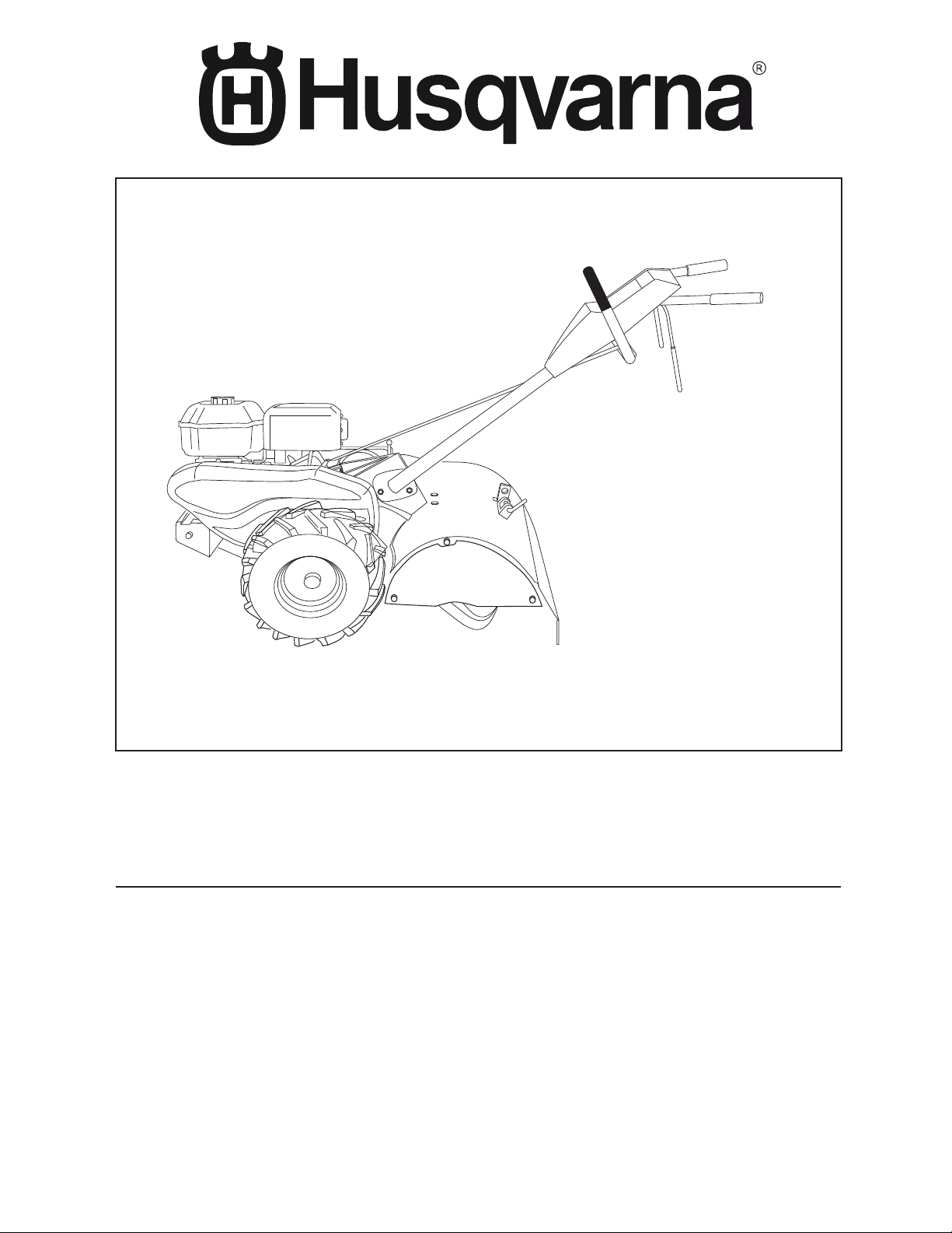
Owner's Manual
532 43 95-06
CRT900
Page 2
SAFETY RULES
Safe Operation Practices for Walk-Behind Powered Ro ta ry Tillers
TRAINING
• Read the Owner’s Manual care ful ly. Be thor ough ly
fa mil iar with the controls and the proper use of the
equip ment. Know how to stop the unit and disengage
the controls quickly.
• Never allow children to operate the equipment. Never
allow adults to op er ate the equipment without proper
instruction.
• Keep the area of operation clear of all persons, par tic u lar ly small children, and pets.
PREPARATION
• Thoroughly inspect the area where the equipment is
to be used and remove all foreign objects.
• Disengage all clutches and shift into neutral before
starting the engine (mo tor).
• Do not operate the equipment with out wearing ad e quate outer gar ments. Wear footwear that will im prove
footing on slippery surfaces.
• Handle fuel with care; it is highly flammable.
• Use an approved fuel container.
• Never add fuel to a running engine or hot engine.
• Fill fuel tank outdoors with extreme care. Never fill fuel
tank indoors.
• Replace gasoline cap securely and clean up spilled
fuel before restarting.
• Use extension cords and receptacles as specified by
the manufacturer for all units with electric drive motors
or electric starting motors.
• Never attempt to make any adjustments while the
engine (motor) is running (except where specifically
rec om mend ed by manufacturer).
OPERATION
• Do not put hands or feet near or under rotating parts.
• Exercise extreme caution when op er at ing on or cross ing gravel drives, walks, or roads. Stay alert for hidden
hazards or traffic. Do not carry pas sen gers.
• After striking a foreign object, stop the engine (motor),
remove the wire from the spark plug, thoroughly in spect
the tiller for any damage, and repair the damage before
restarting and op er at ing the tiller.
• Exercise caution to avoid slipping or falling.
• If the unit should start to vibrate ab nor mal ly, stop the
engine (motor) and check immediately for the cause.
Vi bra tion is generally a warning of trouble.
• Stop the engine (motor) when leaving the operating
position.
• Take all possible precautions when leav ing the ma chine
unattended. Disengage the tines, shift into neutral, and
stop the engine.
• Before cleaning, repairing, or inspecting, shut off the
engine and make certain all moving parts have stopped.
Disconnect the spark plug wire, and keep the wire away
from the plug to prevent accidental starting. Disconnect
the cord on electric motors.
• Do not run the engine indoors; exhaust fumes are
dangerous.
• Never operate the tiller without proper guards, plates,
or other safety protective devices in place.
• Keep children and pets away.
• Do not overload the machine capacity by attempting
to till too deep at too fast a rate.
• Never operate the machine at high speeds on slippery
surfaces. Look behind and use care when backing.
• Never allow bystanders near the unit.
• Use only attachments and accessories approved by
the manufacturer of the tiller.
• Never operate the tiller without good visibility or light.
• Be careful when tilling in hard ground. The tines may
catch in the ground and propel the tiller forward. If this
occurs, let go of the handlebars and do not restrain the
machine.
MAINTENANCE AND STORAGE
• Keep machine, attachments, and accessories in safe
work ing condition.
• Check shear pins, engine mounting bolts, and other
bolts at frequent intervals for proper tightness to be
sure the equip ment is in safe working condition.
• Never store the machine with fuel in the fuel tank inside
a building where ignition sources are present, such
as hot water and space heaters, clothes dryers, and
the like. Allow the engine to cool before storing in any
enclosure.
• Always refer to the operator’s guide instructions for
im por tant details if the tiller is to be stored for an extended period.
- IMPORTANT -
CAUTIONS, IMPORTANTS, AND NOTES ARE A MEANS OF
ATTRACTING ATTENTION TO IMPORTANT OR CRIT I CAL
IN FOR MA TION IN THIS MANUAL.
IMPORTANT: USED TO ALERT YOU THAT THERE IS A
POS SI BIL I TY OF DAM AG ING THIS EQUIP MENT.
NOTE: Gives essential information that will aid you to better understand, incorporate, or execute a particular set of
instructions.
Look for this symbol to point out im por tant safety precautions. It means
CAUTION!!! BE COME ALERT!!! YOUR
SAFE TY IS INVOLVED.
CAUTION: Always disconnect spark
plug wire and place wire where it can not contact spark plug in order to pre vent ac ci den tal starting when setting
up, trans port ing, adjusting or making
re pairs.
WARNING
The engine exhaust from this product con tains chem i cals known to the State of Cal i for nia to cause cancer, birth defects, or other
reproductive harm.
2
Page 3

PRODUCT SPECIFICATIONS
Gasoline Capacity: 3 Quarts
Unleaded Reg u lar (2,8L)
OIL (API-SG-SL): SAE 30 Above 32°F/0°C
(Capacity 20 oz/0,6L) SAE 5w30 Below 32°F/0°C
Spark Plug: Champion
RC12YC
(Gap: .030"/0.76mm)
CONGRATULATIONS on your purchase of a new tiller. It
has been designed, en gi neered and manu fac tured to give
you the best pos sible de penda bil ity and per form ance.
Should you experience any prob lems you can not easily
remedy, please contact your nearest authorized service
center. We have com pe tent, well-trained tech ni cians and
the proper tools to service or repair this unit.
Please read and retain this manual. The in struc tions will
enable you to assemble and main tain your tiller prop erly.
Always observe the “SAFETY RULES”.
CUSTOMER RESPONSIBILITIES
• Read and observe the safety rules.
• Follow a regular schedule in maintaining, caring for
and using your tiller.
• Follow instructions under “Maintenance” and “Stor age”
sections of this Owner’s Manual.
IMPORTANT: THIS UNIT IS EQUIPPED WITH AN INTERNAL
COMBUSTION ENGINE AND SHOULD NOT BE USED ON
OR NEAR ANY UNIMPROVED FOREST-COVERED, BRUSHCOVERED OR GRASS COVERED LAND UNLESS THE
ENGINE'S EXHAUST SYSTEM IS EQUIPPED WITH A SPARK
ARRESTER MEETING APPLICABLE LOCAL LAWS (IF ANY).
IF A SPARK ARRESTER IS USED, IT SHOULD BE MAINTAINED
IN EFFECTIVE WORK ING ORDER BY THE OPERATOR.
IN THE STATE OF CALIFORNIA, A SPARK ARRESTER IS
REQUIRED BY LAW (SECTION 4442 OF THE CALIFORNIA
PUBLIC RESOURCES CODE). OTHER STATES MAY HAVE
SIMILAR LAWS. FEDERAL L AWS APPLY ON FEDERAL L ANDS.
SEE YOUR AUTHORIZED SERVICE CENTER/DEPARTMENT
FOR SPARK ARRESTER.
TABLE OF CONTENTS
SAFETY RULES ..........................................................2
CUSTOMER RESPONSIBILITIES ...............................3
PRODUCT SPECIFICATIONS .....................................3
ASSEMBLY ...............................................................4-6
OPERATION ...........................................................7-10
MAINTENANCE SCHEDULE ....................................11
MAINTENANCE ...................................................11-13
SERVICE & ADJUSTMENTS ...............................14-17
STORAGE .................................................................. 18
TROUBLESHOOTING ............................................... 19
REPAIR PARTS-TILLER.......................................20-26
WARRANTY ..........................................................28-31
3
Page 4
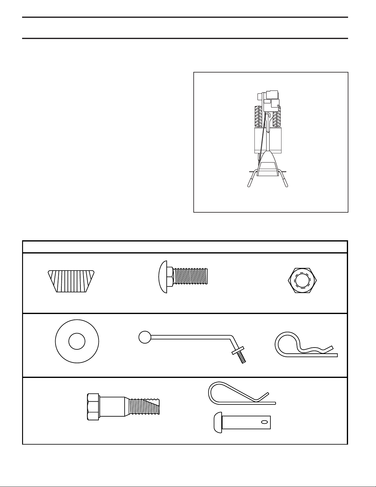
(1) Hairpin Clip
(1) Carriage Bolt
3/8-16 UNC x 1 Grade 5
(1) Center Locknut
3/8-16 UNC
(1) Handle Lock Lever
(1) Flat Washer 13/32 x 1 x 11 Gauge
CONTENTS OF HARDWARE PACK
(2) Handle Locks
(1) Pivot Bolt
3/8-16 UNC Grade 5
Extra Shear Pins & Clips
ASSEMBLY
Your new tiller has been assembled at the factory with exception of those parts left unassembled for shipping purposes.
To ensure safe and proper operation of your tiller all parts and hardware you assemble must be tightened securely. Use
the correct tools as necessary to insure proper tightness.
TOOLS REQUIRED FOR ASSEMBLY
A socket wrench set will make assembly easier. Standard
wrench sizes are listed.
(1) Utility knife
(1) Tire pressure gauge
(1) Pair of pliers
(1) 9/16" wrench
OPERATOR’S POSITION (See Fig. 1)
When right or left hand is mentioned in this manual, it
means when you are in the operating position (standing
behind tiller handles).
LEFT
FRONT
RIGHT
OPERATOR’S
POSITION
Fig. 1
4
Page 5
han
dl
e
s
_10
ASSEMBLY
UNPACKING CARTON (See Fig. 2)
CAUTION: Be careful of exposed
sta ples when handling or disposing
of cartoning material.
IMPORTANT: WHEN UN PACK ING AND AS SEM BLING TILLER,
BE CAREFUL NOT TO STRETCH OR KINK CABLES.
• While holding handle assembly, cut cable ties se cur ing
handle assembly to top frame and depth stake. Let
handle assembly rest on tiller.
• Remove top frame of carton.
• Slowly ease handle assembly up and place on top of
carton.
• Cut down right hand front and right hand rear cor ners
of carton, lay side carton wall down.
• Remove packing material from handle assembly.
HANDLE
AS SEM BLY
rton_3
ca
SHIFT ROD
Fig. 2
INSTALL HANDLE (See Figs. 3, 4, and 5)
• Insert one handle lock (with teeth facing outward) in
gearcase notch. (Apply grease on smooth side of
handle lock to aid in keeping lock in place until handle
assembly is lowered into position.)
VIEWED FROM R.H. SIDE OF TILLER
HANDLE ASSEMBLY
GEARCASE
NOTCH
HANDLE
LOCK
• Grasp handle assembly. Hold in “up” position. Be sure
handle lock remains in gearcase notch. Slide handle
assembly into position.
HANDLE ASSEMBLY
"UP" POSITION
TIGHTEN HANDLE LOCK
LEVER TO HOLD
LOOSEN HANDLE
LOCK LEVER TO MOVE
Fig. 4
• Rotate handle assembly down. Insert rear carriage bolt
first, with bolt head on L.H. side of tiller and loosely
assemble locknut (See Fig. 5).
• Insert pivot bolt in front part of plate and tighten.
• Cut down remaining corners of carton and lay panels
flat.
• Lower the handle assembly. Tighten nut on carriage
bolt so handle moves with some resistance. This will
allow for easier adjustment.
• Place flat washer on threaded end of handle lock lever.
• Insert handle lock lever through handle base and
gearcase. Screw in handle lock lever just enough to
hold lever in place.
• Insert second handle lock (with teeth in ward) in the
slot of the handle base (just inside of washer).
• With handle assembly in lowest position, securely
tight en handle lock lever by rotating clockwise. Leav ing handle assembly in lowest position will make it
easier to remove tiller from carton.
HANDLE
LOCK
GEARCASE
SLOT
FLAT
WASHER
HANDLE LOCK
LEVER
CARRIAGE
BOLT
4
3
les_
d
n
a
h
HANDLE
BASE
LOCKNUT
PIVOT BOLT
Fig. 3
Fig. 5
5
Page 6
ASSEMBLY
ATTACH CLUTCH CABLE (See Fig. 6)
• Hook end of clutch cable through hole in control bar
bracket.
CONTROL BAR
BRACKET
CONTROL
BAR
CLUTCH
CABLE
CONTROL BAR
BRACKET
END OF CLUTCH
CABLE
Fig. 6
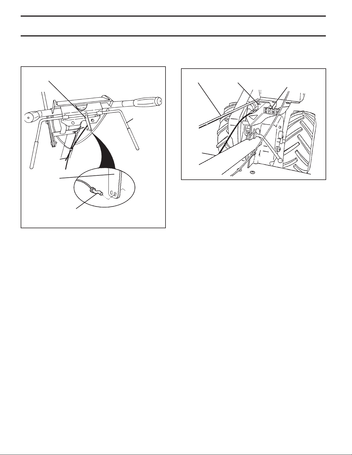
CONNECT SHIFT ROD (See Fig. 7)
• Insert end of shift rod into hole of shift lever indicator.
• Insert hairpin clip through hole of shift rod to secure.
SHIFT
ROD
HAIRPIN
CLIP
SHIFT
LEVER
INDICATOR
Fig. 7
REMOVE TILLER FROM CRATE
• Make sure shift lever indicator is in “N” position (See
Fig. 7)
• Tilt tiller forward by lifting handle. Separate cardboard
cover from leveling shield.
• Rotate tiller handle to the right and pull tiller out of
carton.
CHECK TIRE PRESSURE
The tires on your unit were overinflated at the factory for
shipping purposes. Correct and equal tire pressure is
important for best tilling performance.
• Reduce tire pressure to 20 PSI (1.4 kg/cm2).
HANDLE HEIGHT
• Handle height may be adjusted to better suit operator.
(See “TO ADJUST HANDLE HEIGHT” in the Service
and Adjustments section of this manual).
6
Page 7
OPERATION
KNOW YOUR TILLER
READ THIS OWNER'S MANUAL AND SAFETY RULES BEFORE OPERATING YOUR TILLER.
Compare the illustrations with your tiller to familiarize yourself with the location of various controls and adjustments. Save
this manual for future reference.
These symbols may appear on your Tiller or in literature supplied with the product. Learn and understand their
meaning.
SHIFT LEVER
CHOKE CONTROL
THROTTLE
CONTROL
DRIVE
CONTROL
BAR
DEPTH STAKE
Our tillers conform to the safety standards of the American National Standards Institute.
SHIFT LEVER IN DI CA TOR
LEVELING
SHIELD
RECOIL
STARTER
HANDLE
Fig. 8
MEETS ANSI SAFETY REQUIREMENTS
CHOKE CONTROL - Used when starting a cold engine.
DEPTH STAKE - Controls depth at which tiller will dig.
DRIVE CONTROL BAR - Used to engage tines.
LEVELING SHIELD - Levels tilled soil.
RECOIL STARTER HANDLE - Used to start the engine.
SHIFT LEVER - Used to shift transmission gears.
SHIFT LEVER INDICATOR - Shows which gear the trans-
mis sion is in.
THROTTLE CONTROL - Controls engine speed.
7
Page 8
OPERATION
00155
d
e
pth_st
a
k
e
_
2
The operation of any tiller can result in foreign objects thrown into the eyes, which can
result in severe eye damage. Always wear safety glasses or eye shields before starting
your tiller and while tilling. We recommend a wide vision safety mask for over spectacles
or standard safety glasses.
HOW TO USE YOUR TILLER
Know how to operate all controls before adding fuel and
oil or attempting to start engine.
STOPPING (See Fig. 9)
TINES AND DRIVE
• Release drive control bar to stop movement.
• Move shift lever to “N” (neutral) position.
ENGINE
• Move throttle control to “STOP” position.
• Never use choke to stop engine.
SHALLOWEST
TILLING
(CULTIVATING)
DEEPEST
TILLING
DEPTH
STAKE
TRANSPORT
POSITION
SHIFT LEVER
DRIVE CONTROL BAR
“ENGAGED” PO SI TION
DRIVE CONTROL BAR
“DISENGAGED” PO SI TION
Fig. 9
TINE OPERATION - WITH WHEEL DRIVE
• Always release drive control bar before moving shift
lever into another position.
• Tine movement is achieved by moving shift lever to
( ) till position and engaging drive control bar.
FORWARD - WHEELS ONLY/TINES
STOPPED
• Release drive control bar and move shift lever in di ca tor
to “F” (forward) position. Engage drive control bar and
tiller will move forward.
REVERSE - WHEELS ONLY/TINES STOPPED
• DO NOT STAND DIRECTLY BEHIND TILLER.
• Release the drive control bar.
• Move throttle control to “SLOW” position.
• Move shift lever indicator to “R” (reverse) position.
• Hold drive control bar against the handle to start tiller
movement.
HARD TO SHIFT GEARS
• Briefly engage drive control bar and release or rock tiller
forward and backward until are able to shift gears.
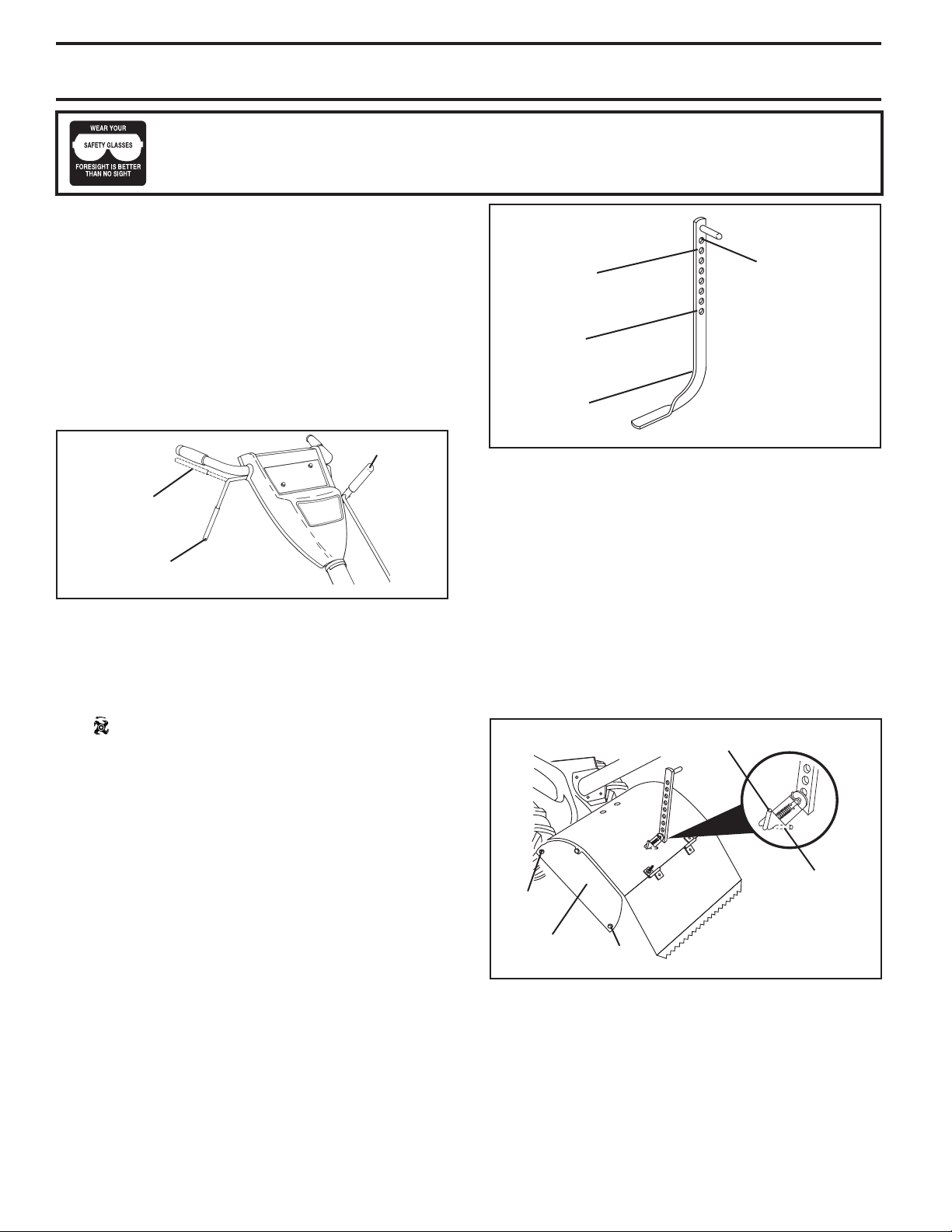
DEPTH STAKE (See Fig. 10)
The depth stake can be raised or lowered to allow you more
versatile tilling and cul ti vat ing, or to more easily transport
your tiller.
Fig. 10
TILLING (See Fig. 11)
• Release depth stake pin. Pull the depth stake up for
increased tilling depth. Place depth stake pin in hole
of depth stake to lock in position.
• Place shift lever indicator in tilling position.
• Hold the drive control bar against the handle to start
tilling movement. Tines and wheels will both turn.
• Move throttle control to “FAST” position for deep tilling.
To cultivate, throttle control can be set at any desired
speed, depending on how fast or slow you wish to
cultivate.
IMPORTANT: ALWAYS RELEASE DRIVE CONTROL
BAR BEFORE MOVING SHIFT LEVER INTO ANOTHER
POSITION.
DEPTH STAKE PIN
“RELEASED” POSITION
“LOCKED”
NUT
“B”
SIDE SHIELD
NUT
“A”
depth
ake_16
_st
POSITION
Fig. 11
TURNING
• Release the drive control bar.
• Move throttle control to “SLOW” position.
• Place shift lever indicator in “F” (forward) position. Tines
will not turn.
• Lift handle to raise tines out of ground.
• Swing the handle in the opposite direction you wish
to turn, being careful to keep feet and legs away from
tines.
8
Page 9
OPERATION
en
gin
e
_
a
r
t
_
4
• When you have completed your turn-around, release
the drive control bar and lower handle. Place shift
lever in till position and move throttle control to de sired
speed. To begin tilling, hold drive control bar against
the handle.
TO TRANSPORT
CAUTION: Before lifting or trans port ing,
allow tiller engine and muffler to cool.
Disconnect spark plug wire. Drain
gasoline from fuel tank.
AROUND THE YARD
• Release the depth stake pin. Move the depth stake
down to the top hole for transporting the tiller. Place
depth stake pin in hole of depth stake to lock in position. This prevents tines from scuffing the ground.
• Place shift lever indicator in “F” (forward) position for
transporting.
• Hold the drive control bar against the handle to start
tiller movement. Tines will not turn.
• Move throttle control to desired speed.
AROUND TOWN
• Disconnect spark plug wire.
• Drain fuel tank.
• Transport in upright position to prevent oil leakage.
BEFORE STARTING ENGINE
IMPORTANT: BE VERY CAREFUL NOT TO ALLOW DIRT
TO ENTER THE ENGINE WHEN CHECKING OR ADDING
OIL OR FUEL. USE CLEAN OIL AND FUEL AND STORE IN
AP PROVED, CLEAN, COVERED CONTAINERS. USE CLEAN
FILL FUNNELS.
CHECK ENGINE OIL LEVEL (See Fig.12)
• The engine in your unit has been shipped, from the
factory, already filled with SAE 30 summer weight oil.
• With engine level, clean area around oil filler plug and
remove plug.
• Engine oil should be to point of overflowing when engine
is level. For ap proxi mate capacity see “PROD UCT
SPEC I FI CA TIONS” on page 3 of this manual. All oil
must meet A.P.I. Service Classification SG-SL.
• For cold weather operation you should change oil for
easier starting (See oil viscosity chart in the Maintenance sec tion of this manual).
• To change engine oil, see the Maintenance section in
this manual.
OIL
LEVEL
OIL
FILLER
OIL DRAIN
PLUG
Fig. 12
PLUG
ADD GASOLINE
• Fill fuel tank to bottom of filler neck. Do not overfill.
Use fresh, clean, regular un lead ed gasoline with a
minimum of 87 octane. (Use of leaded gasoline will
increase carbon and lead oxide deposits and reduce
valve life). Do not mix oil with gasoline. Purchase fuel
in quan ti ties that can be used within 30 days to assure
fuel freshness.
CAUTION: Fill to within 1/2 inch of top
of fuel tank to prevent spills and to allow
for fuel expansion. If gasoline is ac ci den tal ly spilled, move machine away
from area of spill. Avoid creating any
source of ignition until gasoline vapors
have disappeared.
Wipe off any spilled oil or fuel. Do not
store, spill or use gasoline near an
open flame.
IMPORTANT: WHEN OPERATING IN TEMPERATURES
BELOW32°F(0°C), USE FRESH, CLEAN WINTER GRADE
GAS O LINE TO HELP INSURE GOOD COLD WEATHER
START ING.
CAUTION: Alcohol blended fuels (called
gas o hol or using ethanol or methanol) can attract moisture which leads to sep a ra tion and
for ma tion of acids during storage. Acidic gas
can damage the fuel system of an engine while
in storage. To avoid engine problems, the fuel
system should be emptied before stor age of
30 days or longer. Drain the gas tank, start
the engine and let it run until the fuel lines
and carburetor are empty. Use fresh fuel next
sea son. See Storage In struc tions for additional
information. Never use engine or carburetor
cleaner products in the fuel tank or permanent
damage may occur.
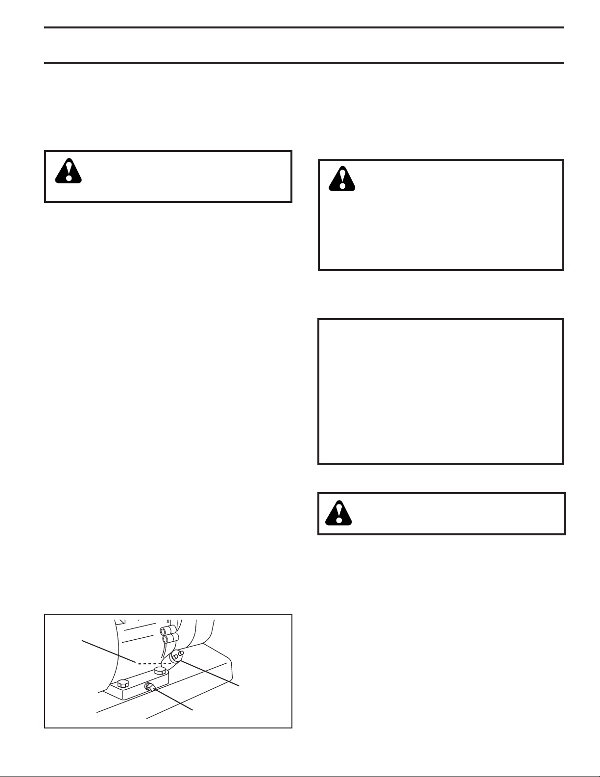
TO START ENGINE (See Fig. 13)
CAUTION: Keep drive control bar in
“DISENGAGED” position when start ing en gine.
When starting engine for the first time or if engine has run
out of fuel, it will take extra pulls of the recoil starter to
move fuel from the tank to the engine.
• Make sure spark plug wire is prop er ly connected.
• Move shift lever indicator to “N” (neutral) position.
• Place throttle control in “FAST” position.
• Turn fuel shut-off valve 1/4 turn to open position.
• Move choke control to choke position.
• Grasp recoil starter handle with one hand and grasp
tiller handle with other hand. Pull rope out slowly until
engine reaches start of com pres sion cycle (rope will
pull slightly harder at this point).
• Pull recoil starter handle quickly. Do not let starter
handle snap back against starter.
• If engine fires but does not start, move choke control
to half choke position. Pull recoil starter handle until
engine starts.
9
Page 10
OPERATION
321
5
4
67
• When engine starts, slowly move choke control to
"RUN" position as engine warms up.
NOTE: A warm engine requires less choking to start.
• Move throttle control to desired running position.
• Allow engine to warm up for a few minutes before
engaging tines.
NOTE: If at a high altitude (3000 feet) or in cold tem per a tures
(below 32°F), the carburetor fuel mixture may need to be
adjusted for best engine performance. See "TO AD JUST
CARBURETOR" in the Service and Adjustments section
of this manual.
NOTE: If engine does not start, see troubleshooting
points.
SPARK PLUG
THROTTLE
CONTROL
CHOKE
CON TROL
e
n
g
i
n
RECOIL
STARTER
e_art_71
• Soil conditions are important for proper tilling. Tines will
not readily penetrate dry, hard soil which may con trib ute
to excessive bounce and difficult handling of your tiller.
Hard soil should be mois tened before tilling; however,
extremely wet soil will “ball-up” or clump during tilling.
Wait until the soil is less wet in order to achieve the
best results. When tilling in the fall, re move vines and
long grass to prevent them from wrapping around the
tine shaft and slowing your tilling operation.
• Do not lean on handle. This takes weight off the wheels
and reduces traction. To get through a really tough
section of sod or hard ground, apply upward pressure
on handle or lower the depth stake.
CULTIVATING
Cultivating is destroying the weeds between rows to pre vent them from robbing nourishment and moisture from the
plants. At the same time, breaking up the upper layer of
soil crust will help retain moisture in the soil. Best digging
depth is 1" to 3" (2.5-7.5 cm). Lower the outer side shields
to protect small plants from being buried.
• Cultivate up and down the rows at a speed which will
allow tines to uproot weeds and leave the ground in
rough condition, promoting no further growth of weeds
and grass (See Fig. 15).
Fig. 13
TILLING HINTS
CAUTION: Until you are accustomed to
handling your tiller, start actual field use
with throttle in slow position (mid-way
between “FAST” and “IDLE”).
• Tilling is digging into, turning over, and breaking up
packed soil before planting. Loose, unpacked soil helps
root growth. Best tilling depth is 4" to 6" (10-15 cm).
A tiller will also clear the soil of unwanted vege ta tion.
The de com po si tion of this vegetable mat ter enriches
the soil. Depending on the climate (rain fall and wind),
it may be advisable to till the soil at the end of the
growing season to further condition the soil.
• You will find tilling much easier if you leave a row
untilled between passes. Then go back between tilled
rows. (See Fig. 14) There are two reasons for doing
this. First, wide turns are much easier to negotiate than
about-faces. Sec ond, the tiller won’t be pulling itself,
and you, toward the row next to it.
Fig. 15
TINE SHEAR PINS
The tine assemblies on your tiller are secured to the tine
shaft with shear pins (See “TINE REPLACEMENT” in the
Service and Ad just ments section of this manual).
If the tiller is unusually overloaded or jammed, the shear
pins are designed to break before internal damage occurs
to the trans mis sion.
• If shear pin(s) break, replace only with those shown in
the Repair Parts section of this manual.
Fig. 14
10
Page 11

MAINTENANCE
MAINTENANCE
SCHEDULE
FILL IN DATES
AS YOU COMPLETE
REGULAR SERVICE
Check Engine Oil Level
Change Engine Oil
Oil Pivot Points
Inspect Air Screen
Inspect Spark Arrester / Muffler
Clean or Replace Air Cleaner Cartridge
Clean Engine Cylinder Fins
Replace Spark Plug
BEFORE EACH USE
EVERY 25 HOURS
EVERY 5 HOURS
EVERY 50 HOURS
SERVICE DATES
1,2
2
1 - Change more often when operating under a heavy load or in high ambient temperatures.
2 - Service more often when operating in dirty or dusty conditions.
EVERY SEASON
RH Gear Case Grease Fitting (1oz.)
GENERAL RECOMMENDATIONS
The warranty on this tiller does not cover items that have
been subjected to operator abuse or negligence. To receive
full value from the warranty, the operator must main tain tiller
as instructed in this manual.
Some adjustments will need to be made periodically to
properly maintain your tiller.
All adjustments in the Service and Adjustments section
of this manual should be checked at least once each
season.
• Once a year you should replace the spark plug, clean
or replace air filter, and check tines and belts for wear.
A new spark plug and clean air filter assure proper
air-fuel mixture and help your engine run better and
last longer.
BEFORE EACH USE
• Check engine oil level.
• Check tine operation.
• Check for loose fasteners.
LUBRICATION
Keep unit well lubricated (See “LUBRICATION CHART”).
LUBRICATION CHART
ENGINE
RH GEAR CASE
GREASE FITTING
IDLER
BRACKET
SAE 30 OR 10W-30 MOTOR OIL
REFER TO MAINTENANCE “EN GINE” SECTION
EP #1 GREASE
WHEEL
HUB
DEPTH
STAKE PIN
LEVELING
SHIELD
HINGES
11
Page 12

MAINTENANCE
Disconnect spark plug wire before performing any maintenance (except car bu re tor adjustment) to
prevent accidental start ing of engine.
Prevent fires! Keep the engine free of grass, leaves, spilled oil, or fuel. Re move fuel from tank
before tipping unit for maintenance. Clean muffler area of all grass, dirt, and debris.
Do not touch hot muffler or cylinder fins as contact may cause burns.
ENGINE
LUBRICATION
Use only high quality detergent oil rated with API service
classification SG-SL. Select the oil’s SAE vis cos i ty grade
according to your expected temperature.
SAE VISCOSITY GRADES
SAE 30
10W-30 / 5W-30
-20 0 30 40
F
C
-30
TEMPERATURE RANGE ANTICIPATED BEFORE NEXT OIL CHANGE
-20 4
-10
10
60
80
20 30 40
Fig. 16
NOTE: Although multi-viscosity oils (5W-30, 10W-30, etc.)
improve starting in cold weather, these multi-viscosity oils
will result in increased oil consumption when used above
40°F (4°C). Check your engine oil level more frequently to
avoid possible engine damage from running low on oil.
Change the oil after every 25 hours of operation or at
least once a year if the tiller is not used for 25 hours in
one year.
Check the crankcase oil level before starting the engine
and after each five (5) hours of continuous use. Add SAE
30 motor oil or equivalent. Tighten oil filler plug securely
each time you check the oil level.
TO CHANGE ENGINE OIL (See Figs. 16 and 17)
Determine temperature range expected before oil change.
All oil must meet API service classification SG-SL.
• Be sure tiller is on level surface.
• Oil will drain more freely when warm.
• Use a funnel to prevent oil spill on tiller, and catch oil
in a suitable con tain er.
• Remove drain plug. For easier removal of plug use
7/16 12 Pt. socket with extension.)
• Tip tiller forward to drain oil.
• After oil has drained completely, replace oil drain plug
and tighten securely.
• Remove oil filler plug. Be careful not to allow dirt to
enter the engine.
• Refill engine with oil. See “CHECK ENGINE OIL LEVEL”
in the Operation section of this manual.
100
oil_visc_chart5_e(drt)
OIL
DRAIN
PLUG
OIL LEVEL
OIL FILLER
PLUG
Fig. 17
AIR CLEANER (See Fig. 18)
Service air cleaner cartridge every twenty-five hours, more
often if engine is used in very dusty conditions.
• Loosen air cleaner screws, one on each side of
cover.
• Remove air cleaner cover.
• Carefully remove air cleaner cartridge. Be care ful. Do
not allow dirt or de bris to fall into carburetor.
• Clean by tapping gently on a flat surface.
• If very dirty or damaged, replace cartridge.
• Clean and re place cover. Tighten screws securely.
IMPORTANT: PETROLEUM SOLVENTS, SUCH AS KER O SENE,
ARE NOT TO BE USED TO CLEAN THE CAR TRIDGE. THEY
MAY CAUSE DETERIORATION OF THE CARTRIDGE. DO
NOT OIL CARTRIDGE. DO NOT USE PRESSURIZED AIR TO
CLEAN OR DRY CARTRIDGE.
COVER
AIR CLEANER
SCREW
Fig. 18
AIR CLEANER
CARTRIDGE
12
Page 13

MAINTENANCE
COOLING SYSTEM (See Fig. 19)
Your engine is air cooled. For proper engine performance
and long life keep your engine clean.
• Clean air screen frequently using a stiff-bristled
brush.
• Keep cylinder fins, levers, and linkage free of dirt and
chaff.
CYLINDER FINS
BLOW ER
HOUS ING
AIR SCREEN
MUFFLER
e
n
gi
n
e
_ar
t
_7
1
Fig. 19
MUFFLER
Do not operate tiller without muffler. Do not tamper with
exhaust system. Damaged mufflers or spark arresters could
create a fire hazard. Inspect pe ri odi cally and re place if
nec es sary. If your engine is equipped with a spark arrester
screen assembly, re move every 50 hours for cleaning and
inspection. Re place if dam aged.
SPARK PLUG
Replace spark plugs at the beginning of each tilling sea son or after every 50 hours of use, whichever comes first.
Spark plug type and gap setting is shown in “PRODUCT
SPEC I FI CA TIONS” on page 3 of this manual.
TRANSMISSION
Once a season, lubricate the right hand side gear case
grease fitting with 1 oz. of EP #1 Grease.
CLEANING
Do not clean your tiller when the engine and transmission
are hot. We do not rec om mend using pressurized water
(gar den hose, etc.) to clean your unit un less the gasket
area around the trans mis sion and the engine muf fler, air
fil ter and car bu re tor are cov ered to keep wa ter out. Wa ter
in en gine will short en the useful life of your tiller.
• Clean engine, wheels, finish, etc. of all foreign matter.
• Keep finished surfaces and wheels free of all gas o line,
oil, etc.
• Protect painted surfaces with au to mo tive type wax.
13
Page 14

SERVICE AND ADJUSTMENTS
CAUTION: Disconnect spark plug wire from spark plug and place wire where it cannot come
into contact with plug.
TILLER
TO ADJUST HANDLE HEIGHT (See Fig. 20)
Select handle height best suited for your tilling conditions.
Handle height will be different when tiller digs into soil.
• First loosen handle lock lever.
• Handle can be positioned at different settings between
“HIGH” and “LOW” positions.
• Retighten handle lock lever securely after adjusting.
HANDLE
(HIGH POSITION)
HANDLE LOCK
LEVER
HANDLE
(LOW POSITION)
Fig. 20
TIRE CARE
CAUTION: When mounting tires, un less beads are seated, over in fla tion
can cause an explosion.
• Maintain 20 pounds of tire pressure. If tire pressures
are not equal, tiller will pull to one side.
• Keep tires free of gasoline or oil which can damage
rubber.
CLEVIS PIN
HAIRPIN CLIP
Fig. 21
TO REMOVE BELT GUARD (See Fig. 22)
NOTE: For ease of removal, remove hairpin clip and
clevis pin from left wheel. Pull wheel out from tiller about
1 inch.
• Remove two (2) screws from side of belt guard.
• Remove hex nut and washer from bottom of belt guard
(located behind wheel).
• Pull belt guard out and away from unit.
• Replace belt guard by reversing above procedure.
BELT GUARD
SCREW
AND WASHER
HEX NUT
AND WASHER
(LOCATED
BEHIND
TIRE)
TO REMOVE WHEEL (See Fig. 21)
• Place blocks under trans mis sion to keep tiller from
tipping.
• Remove hairpin clip and clevis pin from wheel.
• Remove wheel and tire.
• Repair tire and reassemble.
14
SCREW
AND
WASHER
HAIRPIN CLIP AND
CLEVIS PIN
Fig. 22
Page 15

SERVICE AND ADJUSTMENTS
TO REPLACE GROUND DRIVE BELT
(See Fig. 23)
• Remove belt guard (See “TO REMOVE BELT GUARD”
in this section of this manual).
• Remove old belt by slipping off engine pulley first then
remove from transmission pulley.
• Place new belt in groove of transmission pulley and
into engine pulley. BELT MUST BE IN GROOVE ON
TOP OF IDLER PULLEY. NOTE POSITION OF BELT
TO GUIDES.
• Check belt adjustment as described below.
• Replace belt guard.
• Reposition wheel and replace clevis pin and hairpin
clip.
ENGINE
PULLEY
GROUND DRIVE BELT ADJUSTMENT
(See Fig. 23)
For proper belt tension, the extension spring should
have about 5/8 inch stretch when drive control bar is in
“EN GAGED” position. This tension can be attained as
follows:
• Loosen cable clip screw securing the drive control
cable.
• Slide cable forward for less tension and rearward for
more tension until about 5/8 inch stretch is obtained
while the drive control bar is engaged.
• Tighten cable clip screw securely.
CABLE CLIP
SCREW
DRIVE
CONTROL
CABLE
IDLER
PULLEY
TRANS MIS SION PULLEY
Fig. 23
EXTENSION
SPRING
LESS
TEN SION
5/8"
MORE
TEN SION
15
Page 16

SERVICE AND ADJUSTMENTS
TINE REPLACEMENT (See Figs. 24, 25 and
26)
CAUTION: Tines are sharp. Wear
gloves or other protection when han dling tines.
A badly worn tine causes your tiller to work harder and dig
more shallow. Most important, worn tines cannot chop and
shred organic matter as effectively nor bury it as deeply as
good tines. A tine this worn needs to be replaced.
NEW TINE
Fig.24
WORN TINE
• To maintain the superb tilling performance of this ma chine the tines should be checked for sharpness, wear,
and bending, particularly the tines which are next to
the transmission. If the gap between the tines ex ceeds
3-1/2 inches they should be replaced or straight ened
as necessary.
• New tines should be assembled as shown in Fig.
26. Sharp ened tine edges will rotate rearward from
above.
TRANSMISSION
TINE
3-1/2" MAX
tine_2
TINE
SHARP
EDGE
SHEAR PIN
SHEAR PIN
SHARP EDGE
tine_12
Fig. 25
COUNTER
TINE
ROTATION
SHARP EDGE
SHARP
EDGE
HAIRPIN CLIP
SHARP
EDGES
Fig. 26
16
Page 17

SERVICE AND ADJUSTMENTS
ENGINE
TO AD JUST CARBURETOR
The carburetor has been preset at the factory and ad just ment
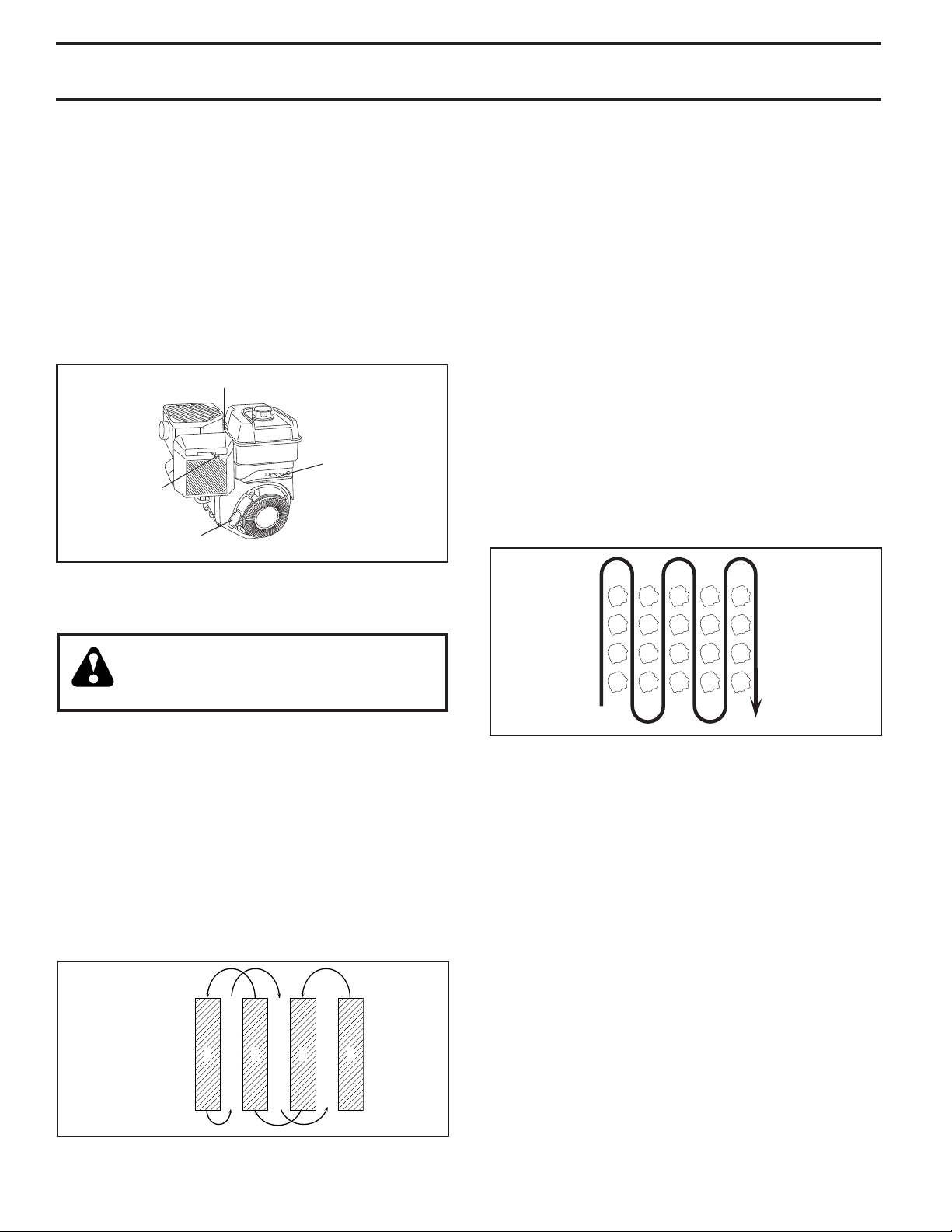
should not be necessary. However, engine per for mance
can be affected by dif fer enc es in fuel, tem per a ture, al ti tude
or load. If the carburetor does need ad just ment, contact
your nearest authorized service center/de part ment
IMPORTANT: NEVER TAMPER WITH THE ENGINE
GOVERNOR, WHICH IS FACTORY SET FOR PROPER ENGINE
SPEED. OVER SPEED ING THE ENGINE ABOVE THE FACTORY
HIGH SPEED SETTING CAN BE DANGEROUS. IF YOU THINK
THE ENGINE-GOVERNED HIGH SPEED NEEDS ADJUSTING,
CONTACT YOUR NEAREST AUTHORIZED SERVICE CENTER/
DEPARTMENT, WHICH HAS THE PROPER EQUIP MENT AND
EXPERIENCE TO MAKE ANY NEC ES SARY ADJUSTMENTS.
17
Page 18

STORAGE
Immediately prepare your tiller for storage at the end of the
season or if the unit will not be used for 30 days or more.
WARNING: Never store the tiller with
gasoline in the tank inside a build ing
where fumes may reach an open flame
or spark. Allow the engine to cool before
storing in any en clo sure.
TILLER
• Clean entire tiller (See “CLEANING” in the Maintenance
section of this manual).
• Inspect and replace belts, if necessary (See belt re place ment instructions in the Service and Ad just ments
section of this manual).
• Lubricate as shown in the Maintenance section of this
manual.
• Be sure that all nuts, bolts and screws are securely
fastened. Inspect moving parts for damage, break age
and wear. Replace if necessary.
• Touch up all rusted or chipped paint surfaces; sand
lightly before painting.
ENGINE
FUEL SYSTEM
IMPORTANT: IT IS IMPORTANT TO PREVENT GUM DEPOSITS
FROM FORMING IN ES SEN TIAL FUEL SYS TEM PARTS SUCH
AS THE CAR BU RE TOR, FUEL FILTER, FUEL HOSE, OR TANK
DURING STOR AGE. ALSO, EXPERIENCE INDICATES THAT
AL CO HOL BLENDED FUELS (CALLED GASOHOL OR USING
ETHA NOL OR METHA NOL) CAN ATTRACT MOIS TURE WHICH
LEADS TO SEPA RA TION AND FORMATION OF ACIDS DUR ING
STOR AGE. ACIDIC GAS CAN DAMAGE THE FUEL SYSTEM
OF AN ENGINE WHILE IN STOR AGE.
• Empty the fuel tank by starting the engine and let it run
until the fuel lines and carburetor are empty.
• Never use engine or carburetor cleaner products in the
fuel tank or permanent.
• Use fresh fuel next season.
NOTE: Fuel stablizer is an acceptable alternative in
minimizing the formation of fuel gum deposits during
storage. Add stabilizer to gasoline in fuel tank or storage
container. Always follow the mix ratio found on stablizer
container. Run engine at least 10 minutes after adding
stablizer to allow the stabilizer to reach the carburetor.
Do not empty the gas tank and carburetor if using fuel
stabilizer.
ENGINE OIL
Drain oil (with engine warm) and replace with clean oil. (See
“ENGINE” in the Maintenance section of this man ual).
CYLINDER(S)
• Remove spark plug.
• Pour 1 ounce (29 ml) of oil through spark plug hole into
cylinder.
• Pull starter handle slowly several times to distribute
oil.
• Replace with new spark plug.
OTHER
• Do not store gasoline from one season to another.
• Replace your gasoline can if your can starts to rust.
Rust and/or dirt in your gasoline will cause problems.
• If possible, store your unit indoors and cover it to give
protection from dust and dirt.
• Cover your unit with a suitable protective cover that
does not retain moisture. Do not use plastic. Plastic
cannot breathe which allows condensation to form and
will cause your unit to rust.
IMPORTANT: NEVER COVER TILLER WHILE EN GINE AND
EX HAUST AREAS ARE STILL WARM.
18
Page 19

TROUBLESHOOTING POINTS
PROBLEM CAUSE CORRECTION
Will not start 1. Out of fuel. 1. Fill fuel tank.
2. Engine not “CHOKED” properly. 2. See “TO START ENGINE” in Operation section.
3. Engine flooded. 3. Wait several minutes before attempting to start.
4. Dirty air cleaner. 4. Clean or replace air cleaner cartridge.
5. Water in fuel. 5. Empty fuel tank and carburetor, and refill tank with fresh,
clean gasoline.
6. Clogged fuel tank. 6. Remove fuel tank and clean.
7. Loose spark plug wire. 7. Make sure spark plug wire is seated properly on plug.
8. Bad spark plug or improper gap. 8. Replace spark plug or adjust gap.
9. Carburetor out of adjustment. 9. Make necessary adjustments.
10. Oil soaked air filter. 10. Replace air filter.
Hard to start 1. Throttle control not set properly. 1. Place throttle control in “FAST” position.
2. Dirty air cleaner. 2. Clean or replace air cleaner cartridge.
3. Bad spark plug or improper gap. 3. Replace spark plug or adjust gap.
4. Stale or dirty fuel. 4. Empty fuel tank and refill tank with fresh, clean gasoline.
5. Loose spark plug wire. 5. Make sure spark plug wire is seated properly on plug.
6. Carburetor out of adjustment. 6. Make necessary adjustments.
Loss of power 1. Engine is overloaded. 1. Set depth stake for shallower tilling.
2. Dirty air cleaner. 2. Clean or replace air cleaner cartridge.
3. Low oil level/dirty oil. 3. Check oil level/change oil.
4. Faulty spark plug. 4. Clean and regap or change spark plug.
5. Oil in fuel. 5. Empty and clean fuel tank and refill tank, and clean
car bu re tor.
6. Stale or dirty fuel. 6. Empty fuel tank and refill tank with fresh, clean gasoline.
7. Water in fuel. 7. Empty fuel tank and carburetor, and refill tank with fresh,
clean gasoline.
8. Clogged fuel tank. 8. Remove fuel tank and clean.
9. Spark plug wire loose. 9. Connect and tighten spark plug wire.
10. Dirty engine air screen. 10. Clean engine air screen.
11. Dirty/clogged muffler. 11. Clean/replace muffler.
12. Carburetor out of adjustment. 12. Make necessary adjustments.
13. Poor compression. 13. Contact an authorized service center/department.
Engine overheats 1. Low oil level/dirty oil. 1. Check oil level/change oil.
2. Dirty engine air screen. 2. Clean engine air screen.
3. Dirty engine. 3. Clean cylinder fins, air screen, and muffler area.
4. Partially plugged muffler. 4. Remove and clean muffler.
5. Improper carburetor adjustment. 5. Adjust carburetor to richer position.
Excessive bounce/ 1. Ground too dry and hard. 1. Moisten ground or wait for more favorable soil
difficult handling conditions.
Soil balls up or clumps 1. Ground too wet. 1. Wait for more favorable soil conditions.
Engine runs but tiller 1. Drive control bar is not engaged. 1. Engage drive control.
won’t move 2. V-belt not correctly adjusted. 2. Inspect/adjust V-belt.
3. V-belt is off pulley(s). 3. Inspect V-belt.
Engine runs but labors 1. Tilling too deep. 1. Set depth stake for shallower tilling.
when tilling 2. Throttle control not properly adjusted. 2. Check throttle control setting.
3. Carburetor out of adjustment. 3. Make necessary adjustments.
Tines will not rotate 1. Shear pin(s) broken. 1. Replace shear pin(s).
19
Page 20

REPAIR PARTS
TILLER - - MODEL NUMBER CRT900 (96093001301), PRODUCT NUMBER 960 93 00-13
HANDLE ASSEMBLY
KEY PART
NO. NO. DESCRIPTION
2 532 42 76-43 Grip, Handle
4 532 15 92-28 Bar Assembly, Control
6 532 18 06-85 Panel, Control
8 871 19 10-08 Screw, Truss Hd. #10-24 unc x 1/2
10 532 12 47-97 Grip, Handle
11 532 12 47-88 Clip, Hairpin
12 532 08 13-28 Bolt, Shoulder
13 532 18 74-97 Handle, Shift
14 532 10 93-13 Grommet, Rubber
15 532 10 93-37 Rod, Shift
16 872 11 06-08 Bolt, Carriage 3/8-16 x 1 Gr. 5
17 532 10 92-29 Lock, Handle
18 873 68 06-00 Nut, Crownlock 3/8-16 unc
19 819 13 16-11 Washer 13/32 x 1 x 11 Ga.
20 532 10 92-28 Lever, Lock, Handle
21 532 18 11-27 Handle
(ANDLE?ASSY??
KEY PART
NO. NO. DESCRIPTION
23 532 08 67-77 Screw, Hex Washer SLT#10-24 x .50
24 532 00 94-84 Clip
26 532 15 92-31 Cable, Clutch
27 873 90 04-00 Nut, Hex Flange 1/4-20 unc
29 873 73 10-00 Nut, Keps #10-24 unc
30 532 10 41-64 Tie, Cable
31 532 15 06-96 Bolt, Pivot
33 872 14 04-04 Bolt, Carriage 1/4-20 unc x 1/2
37 532 10 26-04 Grip, Bar, Control
41 532 10 27-44 Clamp, Bar, Control
NOTE: All component dimensions given in U.S. inches.
1 inch = 25.4 mm
20
Page 21

REPAIR PARTS
TILLER - - MODEL NUMBER CRT900 (96093001301), PRODUCT NUMBER 960 93 00-13
MAINFRAME, LEFT SIDE
KEY PART
NO. NO. DESCRIPTION
3 873 22 06-00 Nut, Hex 3/8-16
4 532 43 24-20 Shield, Inner Belt Guard RT
5 532 16 43-29 Pin Spirol Flared
6 532 11 01-11 Lever, Shift
7 872 11 04-04 Bolt, Carriage 1/4-20 x 1/2 Gr. 5
8 532 00 87-00 Plate, Shift Indicator
9 532 08 67-77 Screw, Hex, Washer Head, Slotted
#10-24 x 1/2
10 532 00 94-84 Clip
12 873 51 04-00 Nut, Keps Hex 1/4-20 unc
13 823 23 05-06 Screw, Set, Hex 5/16-18 x 3/8
14 532 11 06-52 Spacer, Split 0.327 x 0.42 x 2.09
15 819 11 11-16 Washer 11/32 x 11/16 x 16 Ga.
16 532 14 51-02 Sheave, Transmission
19 812 00 00-28 Retainer, Ring
21 532 15 61-17 Spacer, Split
22 874 77 05-08 Bolt, Fin Hex 5/16-24 unf x 1/2
23 532 10 21-90 Tire
532 15 07-40 Rim
532 12 47-18 Tire Valve
24 532 12 68-75 Rivet, Drilled
25 532 12 47-88 Clip, Hairpin
26 532 16 67-92 Guard, Belt
MAINFRAME?LEFT?
KEY PART
NO. NO. DESCRIPTION
27 532 13 28-01 Belt, V
28 532 10 46-79 Pulley, Idler
29 812 00 00-32 Ring, Klip
30 532 15 92-29 Bracket, Idler
31 532 10 21-94 Bolt Fin Hex 3/8-16 unc x10
32 532 10 21-41 Shaft, Idler Arm
33 874 76 06-16 Bolt, Hex 3/8-16 x 1
34 532 10 21-73 Counterweight
36 532 10 23-31 Bracket, Reinforcement, L. H.
37 532 13 08-12 Sheave, Engine
38 874 76 05-44 Bolt, Fin Hex 5/16-18 unc x 2-3/4
39 532 14 00-62 Cap, Plunger Blk
40 532 17 04-88 Screw Hex Wsh Slt #10-24 x 1/2
44 873 80 05-00 Nut Lock Hex w/Ins 5/16-18 unc PL
65 873 97 05-00 Nut Lock Hex Flange
66 819 13 13-12 Washer 13/32 x 13/16 x 12 Ga.
67 874 76 05-24 Bolt, Hex 5/16-18 x 1-1/2
68 873 51 06-00 Nut, Keps Hex 3/8-16 unc
69 532 16 41-73 Keeper Belt Engine
NOTE: All component dimensions given in U.S. inches.
1 inch = 25.4 mm
21
Page 22

REPAIR PARTS
TILLER - - MODEL NUMBER CRT900 (96093001301), PRODUCT NUMBER 960 93 00-13
MAINFRAME, RIGHT SIDE
KEY PART
NO. NO. DESCRIPTION
2 873 97 05-00 Locknut, Hex, Flange 5/16-18
5 532 10 23-32 Bracket, Reinforcement RH
7 532 10 21-73 Counter Weight
10 874 76 05-24 Bolt, Hex 5/16-18 x 1-1/2
11 532 12 47-88 Clip, Hairpin
12 532 12 68-75 Rivet, Drilled
13 532 10 21-90 Tire
532 15 07-40 Rim
532 12 47-18 Tire Valve
MAINFRAME?RIGHT??R
KEY PART
NO. NO. DESCRIPTION
15 - - - - - - - - Engine, Briggs & Stratton
Model No. 121002-1380-B8 (Order
parts from Engine Manufacturer)
44 873 51 06-00 Nut, Keps Hex 3/8-16 unc
NOTE: All component dimensions given in U.S. inches
1 inch = 25.4 mm
For engine service and replacement parts, call the toll free
number for your engine manufacturer listed below:
Briggs & Stratton 1-800-233-3723
22
Page 23

REPAIR PARTS
TILLER - - MODEL NUMBER CRT900 (96093001301), PRODUCT NUMBER 960 93 00-13
TRANSMISSION
12
13
15
11
9
10
8
5
7
2
24
25
52
transmission_19.5b_r1
6
5
4
51
27
35
53
58
3
44
18
21
19
20
28
50
KEY PART
NO. NO. DESCRIPTION
1 532 18 85-54 Transmission Assembly
(In cludes Key Nos. 2-53)
2 532 18 84-82 Gearcase, L.H. w/Bearing
(In cludes Key No. 4)
3 532 43 10-22 Gasket, Gearcase
4 532 00 50-20 Bearing, Needle
5 532 00 13-70 Washer, Thrust 5/8 x 1.10 x 1/32
6 532 13 73-35 Pinion, Input
7 532 14 51-01 Shaft, In put
8 532 12 47-92 Bearing, Needle
9 532 15 44-67 Washer, Seal
10 532 12 46-97 Ball, Steel
11 532 10 03-71 Spring, Shift, Fork
12 532 10 61-60 O-Ring
13 532 14 21-45 Arm, Shift
14 532 00 83-53 Fork, Shift
15 812 00 00-39 Ring, Klip
16 532 15 44-66 Shaft, Shift
18 532 00 43-58 Washer
19 812 00 00-40 Ring, Klip
20 532 10 21-14 Gear, As sem bly, Reverse Idler
(Includes Key Nos. 21 and 22)
21 532 10 21-15 Gear, Re verse Idler
22 532 00 68-03 Bearing, Needle
23 532 10 21-11 Shaft, Re verse Idler
24 810 04 07-00 Washer, Lock 7/16
25 873 61 07-00 Nut, Hex 7/16-20
27 532 14 30-09 Bearing, Shaft, Ground Drive L.H.
28 532 10 63-90 Spacer 0.765 x 1.125 x 1.23
29 532 10 21-34 Chain #35-50 Pitch
29
16
9
14
18
23
22
38
37
18
32
30
36
33
31
37
40
39
62
34
18
18
41
48
49
42
60
25
24
44
43
53
KEY PART
NO. NO. DESCRIPTION
30 532 15 07-37 Ground Shaft Assembly
31 532 14 30-08 Bearing, Shaft, Ground Drive R.H.
32 532 10 63-88 Spacer 0.70 x 1.00 x 1.150
33 532 10 21-21 Sprocket and Gear Assembly
34 532 10 21-12 Shaft, Re duc tion (2nd)
35 532 10 21-01 Screw, Whiz, Lock 5/16-18 x 3-1/2
36 532 15 43-55 Sprocket Assembly w/Bearing
(Includes Key Nos. 37 and 38)
37 532 12 47-91 Bearing, Needle
38 532 15 43-56 Sprocket, Tine
39 532 10 53-45 Gear, Clus ter, Red 1st & 2nd
40 532 10 53-46 Gear, Re verse
41 532 00 83-58 Shaft, Re duc tion (1st)
42 532 00 42-20 Washer, Thrust
43 532 10 61-46 Spacer 1.01 x 1.75 x 0.760
44 532 15 52-36 Seal Asm, Oil
48 532 18 84-85 Gearcase, R.H. w/Bearing
(In cludes Key No. 8)
49 532 43 14-85 Shaft, Tine
50 532 10 61-47 Chain, Roller #50-50 Pitch
51 817 72 04-08 Screw 1/4-20 x 1/2
52 873 22 05-00 Nut, Hex 5/16-18
53 532 16 51-40 Kit, Bearing
58 532 17 95-20 Bolt Shoulder 1/4-20 unc x .875
60 532 18 32-26 Fitting Grease
62 532 43 10-15 Spacer 1.015 x 1.50 x .650
- - 532 00 60-66 Grease, Plastilube #1
NOTE: All component dimensions given in U.S. inches.
1 inch = 25.4 mm
23
Page 24

REPAIR PARTS
TILLER - - MODEL NUMBER CRT900 (96093001301), PRODUCT NUMBER 960 93 00-13
TINE SHIELD
27
24
23
16
26
28
25
33
29
32
3
23
4
18
5
24
22
21
5
6
7
23
20
19
8
13
5
9
5
16
29
14
14
1
TINE?SHIELD??IN?R
KEY PART
NO. NO. DESCRIPTION
1 873 90 05-00 Nut, Lock Hex Flange 5/16-18
3 532 00 83-93 Pin, Stake, Depth
4 812 00 00-35 Ring, Klip
5 532 18 08-47 Bolt, Rdhd Sqnk 5/16-18 x 3/4
6 532 00 83-94 Spring
7 532 00 83-92 Bracket, Latch
8 532 10 92-30 Spring, Depth Stake
9 532 13 88-63 Shield, Tine
13 872 11 05-10 Bolt, Carriage 5/16-18 x 1-1/4
14 532 12 43-43 Bracket, Shield Tine
16 873 90 04-00 Nut, Hex Flange 1/4-20 unc
18 872 04 04-10 Bolt, Carriage 1/4-20 x 1-1/4 Gr.
19 532 10 27-01 Grip
20 873 22 06-00 Nut, Hex 3/8-16
21 532 10 21-56 Stake, Depth
22 874 93 06-32 Bolt, Hex 3/8-16 x 2
KEY PART
NO. NO. DESCRIPTION
23 532 00 44-40 Hinge
24 872 14 04-04 Bolt, Carriage 1/4-20 x 1/2 Gr. 5
25 532 12 47-17 Cap, Vinyl
26 532 10 92-27 Pad, Idler
27 532 12 54-51 Shield, Leveling
28 532 12 05-88 Pin, Hinge
29 532 40 39-60 Shield, Side
30 873 97 05-00 Nut Lock Hex Flange
32 873 22 04-00 Nut Fin Hex 1/4-20 unc
33 810 04 04-00 Washer Lock Hvy Helical 1/4
38 873 51 05-00 Nut, Keps Hex 5/16-18 unc
NOTE: All component dimensions given in U.S. inches.
1 inch = 25.4 mm
24
Page 25

REPAIR PARTS
TILLER - - MODEL NUMBER CRT900 (96093001301), PRODUCT NUMBER 960 93 00-13
TINE ASSEMBLY
KEY PART
NO. NO. DESCRIPTION
1 532 00 44-59 Tine, Outer, L.H.
2 532 13 26-73 Clevis Pin
3 532 00 65-54 Tine, Inner, L.H.
4 532 12 46-60 Retainer, Spring Zinc
5 532 13 27-21 Assembly, Hub and Plate, L.H.
8 874 61 06-16 Bolt, Hex 3/8-24 x 1
9 532 00 44-60 Tine, Outer, R.H.
TINE?IPB???R
KEY PART
NO. NO. DESCRIPTION
10 532 13 27-22 Assembly, Hub and Plate, R.H.
11 532 00 65-55 Tine, Inner, R.H.
34 873 54 06-00 Nut Crownlock 3/8-24
NOTE: All component dimensions given in U.S. inches.
1 inch = 25.4 mm
25
Page 26

REPAIR PARTS
TILLER - - MODEL NUMBER CRT900 (96093001301), PRODUCT NUMBER 960 93 00-13
DECALS
3
2
1
5
6
4
7
9
KEY PART
NO. NO. DESCRIPTION
1 532 42 91-96 Decal, Belt Guard Badge
2 532 43 23-62 Decal, Husqvarna, Control Panel
3 532 43 14-65 Decal, Control Tine
4 532 42 83-28 Decal, Tine Shield
5 532 11 06-14 Decal, Hand Placement
6 532 10 21-80 Decal, Shift Indicator
7 532 42 29-72 Decal, Warning
8 532 43 22-78 Decal, Engine, Air Cleaner
9 532 12 00-76 Decal, Warning, Rotating Tines
10 532 40 91-43 Decal, Engine, Fuel Tank, 8.5
- - 532 43 95-06 Owner’s Manual (English)
- - 532 43 95-07 Owner’s Manual (French)
8
10
26
Page 27

SERVICE NOTES
27
Page 28

Consumer Wheeled Products
– Limited Warranty
Husqvarna warrants to the original retail purchaser that this Husqvarna® product is free from defects in material or workmanship
under normal use and maintenance from the date of retail purchase for the applicable Warranty Period shown on Exhibit A
. Certain
components (e.g., engines and transmissions) are excluded from coverage, and other limitations apply, as described in this document.
Husqvarna will repair or replace at its discretion, any defective product or part covered by the Limited Warranty, free of charge at any
authorized Husqvarna Servicing Dealer/Center using original OEM Husqvarna replacement parts, subject to the limitations and
exclusions described below. Husqvarna does not offer an over-the-counter exchange program .
THIS LIMITED WARRANTY IS THE SOLE EXPRESS WARRANTY PROVIDED BY HUSQVARNA. ANY WARRANTY
THAT MAY BE IMPLIED BY LAW (INCLUDING ANY IMPLIED WARRANTY OF FITNESS FOR A PARTICULAR
PURPOSE OR USE AND IMPLIED WARRANTY OF MERCHANTABILITY) IS LIMITED TO THE DURATION OF THE
APPLICABLE WARRANTY PERIOD UNDER THIS LIMITED WARRANTY. THIS LIMITED WARRANTY MAY BE
MODIFIED ONLY BY HUSQVARNA. SOME STATES DO NOT ALLOW LIMITATIONS ON HOW LONG AN IMPLIED
WARRANTY LASTS, SO THE ABOVE LIMITATIONS MAY NOT APPLY TO YOU. THIS LIMITED WARRANTY GIVES
YOU SPECIFIC LEGAL RIGHTS, AND YOU MAY ALSO HAVE OTHER RIGHTS WHICH VARY FROM STATE TO STATE.
THIS WARRANTY IS GIVEN ONLY
BY HUSQVARNA. THE ABOVE REMEDIES ARE THE EXCLUSIVE REMEDIES FOR
ANY BREACH OF THIS LIMITED WARRANTY. HUSQVARNA AND ITS AFFILIATED COMPANIES SHALL NOT BE
LIABLE FOR ANY SPECIAL, INCIDENTAL OR CONSEQUENTIAL DAMAGE, INCLUDING LOST PROFITS RESULTING
FROM ANY SUCH BREACH, AND ALL SUCH DAMAGES ARE HEREBY DISCLAIMED. SOME STATES DO NOT ALLOW
THE EXCLUSION OR LIMITATION OF INCIDENTAL OR CONSEQUENTIAL DAMAGES, SO THE ABOVE LIMITATIONS
MAY NOT APPLY TO YOU.
LIMITATIONS AND EXCLUSIONS
1. Engines, Transmissions and certain other components are NOT covered. This Limited Warranty does not cover
any of the
following:
(a) Engines and Attachments. Except where otherwise indicated on Exhibit A, all Engines and Attachments are not covered by
this warranty. In most cases, these items are NOT manufactured by Husqvarna in which case they may be covered separately by
their respective manufacturer’s warranties if one is provided and included with the product at the time of purchase. All such
claims must be submitted and sent to the appropriate manufacturer or as otherwise directed in those separate warranties.
Husqvarna is not authorized to handle warranty adjustments or repairs on engines manufactured by Briggs & Stratton, Honda,
Kawasaki, or Kohler (exception – models equipped with LCT engines). Husqvarna does not assume any warranty obligation of
the other manufacturer’s engines.
(b) Transmissions. Except where otherwise indicated on Exhibit A, Transmission / Transaxle (including Drive Systems) are not
covered by this warranty. In most cases, these items are NOT manufactured by Husqvarna in which case they may be covered
separately by their respective manufacturer’s warranties if one is provided and included with the product at the time of purchase.
The following transmission / transaxle manufacturers, Dana, Hydro-Gear, Tuff-Torq provide a warranty for the transmission /
transaxle to the ultimate purchaser or to Husqvarna. Husqvarna will assign the transmission / transaxle manufacturer’s warranty
or any rights thereof to the original purchaser of the unit. To obtain transmission / transaxle warranty service, first contact the
retailer who you purchased the unit from. Should you require assistance or have any questions concerning transmission / transaxle
warranty coverage, contact Husqvarna directly at our website www.husqvarna.com
or call 800-487-5951 for an authorized
Husqvarna service provider. All such claims must be submitted and sent to the appropriate manufacturer or as otherwise directed
in those separate warranties. Husqvarna is not authorized to handle warranty adjustments or repairs on transmissions or transaxles.
Husqvarna does not assume any warranty obligation of the above listed manufacturers (for exceptions – see Exhibit
(c) Expendable Parts. This Limited Warranty does not cover general maintenance parts and items (“Expendable Parts”),
A).
including without limitation spark plugs, bulbs, filters, lubricants, starter cords, belts, blades, and blade adapters.
(d) Emissions Control Components. This Limited Warranty does not cover Emissions control equipment and components to the
extent regulated by the U.S. Environmental Protection Agency or similar state agencies. Such equipment and components are
covered by a separate emission control warranty statement supplied with your new product. Please consult this separate warranty
statement for details.
Any COMMERCIAL, INSITUTIONAL, AGRICULTURAL, INDUSTRIAL, INCOME PRODUCING, or RENTAL use will result in either No
2.
Warranty or a Shortened Warranty Period Depending on the product; there is either NO WARRANTY or a reduced warranty if the product is used for commercial,
institutional, agricultural, industrial, income producing, or rental purposes. Please refer to Exhibit A.
3. Owner’s (Your) Responsibilities. To preserve your rights under this Limited Warranty, you must demonstrate reasonable care
and use of the product, including, following the preventative maintenance, storage, fuel and oil usages as prescribed in the enclosed
operator’s manual. For example, the following items are the Owner’s responsibility and are not
covered by this Limited Warranty:
a. Set-up and pre-delivery service, and engine tune-ups.
b.Adjustments after the first (30) thirty days of purchase and beyond, such as throttle cable, belt guides adjustments.
28
Page 29

c. Preventative maintenance as outlined in the operator’s manual.
In addition, you must cease using the product immediately upon any failure or damage. The product should be taken to an authorized
Husqvarna servicing dealer prior to any further use.
4. Damages resulting from normal aging, wear and tear or neglect are NOT covered. The Limited Warranty does not cover
damage other than that resulting from defects in material or workmanship. The following are NOT considered defects in material or
workmanship, and therefore are NOT covered.
(a) Abrasion to mower decks;
(b) Tires damaged by external punctures;
(c) Natural discoloration of materials due to ultraviolet light;
(d) Damage to cutting equipment by way of contact with, rocks, or other non-approved materials and/or structures;
In addition, this Limited Warranty does not cover damages, malfunctions or failures resulting from abuse or neglect of the product
related to or including any of the following:
(e) Failure to provide or perform required maintenance services as prescribed in the operator’s manual;
(f) Abuse, misuse, neglect, modifications, alterations, normal wear, improper servicing, use of unauthorized attachments, Lack of
lubrication or engine failure, due to the use of oils that do not meet Engine manufacturer’s specifications;
(g) Use of gasohol, containing methanol (wood alcohol). Gasohol which contains a maximum 10% ethanol (grain alcohol) or
15% MTBE (methyl/tertiary/butyl/ether) is approved;
(h) Use of ether or any starting fluids;
(i) Pressure cleaning or steam cleaning the product;
(j) Use of spark plugs other than those meeting emission performance requirements listed in the operator’s manual;
(k) Tampering with engine speed governor or emission components, or running engines above specified and recommended
engine speeds as listed in your operator’s manual;
(l) Operation of the unit with improperly installed/removed or modified cutting shields, guards, or safety devices;
(m) Any removed/damaged air filter, excessive dirt, abrasives, salt water, moisture, corrosion, rust, varnish, stale fuel, or any
adverse reaction due to incorrect storage procedures;
(n) Failures due to improper set up, pre-delivery service or repair service by anyone other than an authorized Husqvarna
servicing dealer during the warranty period;
(o) Dirt contaminated grease or oil, use of incorrect type of greases or oils, failure to comply with recommended greasing
intervals, water or moisture damage, and/or improper storage;
(p) Sprayers pumping or spraying caustic or flammable materials, lack of or broken strainers; or
(q) Continued use of product, after initial operational problem or failure occurs.
HOW TO OBTAIN SERVICE
5. Authorized Husqvarna Servicing Dealer/Center. In order to obtain warranty coverage it is your responsibility (at your
expense) to deliver or ship your Husqvarna unit to an authorized Husqvarna Servicing Dealer/Center and arrange for pick-up or return
of your unit after the repairs have been made. If you do not know the location of your nearest authorized Husqvarna Servicing Dealer,
call Husqvarna, at 1-800-487-5951 during the hours of 8:00 AM to 8:00 PM Eastern Standard Time, or visit www.husqvarna.com
.
Should you require assistance or have questions concerning this Limited Warranty, you may contact us at 800-487-5951 during the
hours of 8:00 AM to 8:00 PM Eastern Standard Time or contact us through the web at www.husqvarna.com
.
6. Documentation Required. You must maintain and present Proof of purchase (including date, product model and, if applicable,
engine serial number) to an authorized Husqvarna Servicing Dealer for warranty service under this Limited Warranty. Proof of
purchase rests solely with the owner-customer. Husqvarna encourages you to register your product online at
www.usa.husqvarna.com
to help ensure, among other things, that you can be notified of important product information. However,
registering your product is not a condition of warranty service.
Husqvarna Consumer Outdoor Products N.A., Inc.; Husqvarna Professional Products, Inc.
9335 Harris Corners Parkway Charlotte, NC 28269
575 49 43-01 R3 2010
29
Page 30

Consumer Wheeled Warranty Chart 2010
Exhibit A
Consumer (personal,
household use only)
Product/Component
Riding Lawn Tractors:
Frame, Chassis, Front Axle 5 Years NO WARRANTY NO WARRANTY
Engine*
Transmission (if made by
Husqvarna/Peerless)
Transmission (if third party)** ** ** **
Battery 1 Year Pro-rated NO WARRANTY NO WARRANTY
Other Non-Expendable Components 3 Years NO WARRANTY NO W ARRANTY
Residential Zero Turn Mowers (RZ Only)
Engine*
Transmission ** ** NO WARRANTY NO WARRANTY
Battery 1 Year Pro-rated NO WARRANTY NO WARRANTY
Other Non-Expendable Components 3 Years NO WARRANTY NO WARRANTY
Residential Zero Turn Mowers (MZ & EZ )
Engine*
Transmission ** ** ** **
Battery 1 Year Pro-rated 1 Year Pro-rated NO WARRANTY
Other Non-Expendable Components 3 Years 1 Year NO WARRANTY
LE475 Edger
Engine*
Other Non-Expendable Components 2 Years 90 days 90 days
Walk Behind Mowers
Engine*
Battery 1 Year Pro-rated NO WARRANTY NO WARRANTY
Other Non-Expendable Components 2 Years NO WARRANTY NO WARRANTY
Snow Throwers
Engine*
Engine*
Other Non-Expendable Components 2 Years 90 days 90 days
Tillers
Engine*
Battery 1 Year Pro-rated NO WARRANTY NO WARRANTY
Other Non-Expendable Components 2 Years NO WARRANTY NO WARRANTY
Tiller Tines
Hovering Trimmers
Engine*
Other Non-Expendable Components 2 Years 1 Year 90 days
* See Separate Engine Manufacturer's or Manufacturer's warranty
LCT Engines on specific Snow Throwers & Tillers, warranty through
** See reference 1 (b) of the warranty statement.
RZ - Two (2) Year Consumer warranty, parts & labor, with Hydro-Gear Distributor network.
EZ - One (1) Year Commercial warranty, parts & labor, with Husqvarna.
Two (2) Year Consumer warranty, parts & labor, with Hydro-Gear Distributor network.
MZ - Two (2) Year Commercial warranty, parts & labor, with Hydro-Gear Distributor network.
*** "Limited Lifetime Warranty" on Tiller tines is for the life of the product or 7 (seven) years after the last date of the complete
unit's final production, whichever comes first.
* * *
3 Years NO WARRANTY NO WARRANTY
* * *
* * *
* * *
* * *
***
**
* *
***
* * *
Consumer Commercial Rental
Commercial (any commercial,
professional, institutional,
arigculutral, or income producing
use, other than Rental Use)
NO WARRANTY NO WARRANTY
Husqvarna.
Rental (any rental
usage)
*
*
30
Page 31

Consumer Wheeled Warranty Chart 2010
Exhibit A
Consumer (personal,
household use only)
Product/Component
Front Mounted Deck Riders
Engine*
Transmission 2 Years NO WARRANTY NO WARRANTY
Battery 1 Year Pro-rated NO WARRANTY NO WARRANTY
Other Non-Expendable Components 2 Years NO WARRANTY NO WARRANTY
Cultivators
Battery 1 Year Pro-rated NO WARRANTY NO WARRANTY
Other Non-Expendable Components 2 Years NO WARRANTY NO WARRANTY
Pressure Washers
Model 5525PW:
Engine*
Pump 2 Years NO WARRANTY NO WARRANTY
Other Non-Expendable Components 2 Years NO WARRANTY NO WARRANTY
All other Pressure Washers (6027PW
Engine*
Pump 2 Years 2 Years NO WARRANTY
Other Non-Expendable Components 2 Years 2 Years NO WARRANTY
Generators
Engine*
Other Non-Expendable Components*
Spreaders
Spreader 1 Year 1 Year 1 Year
Robotic Mowers
Robotic Mower 2 Years 90 days 90 days
Battery 1 Year 1 Year 1 Year
Parts & Accessories (if purchased)
Pt&A i (if h d)
Accessories (e.g., grass catcher, bumper
guard accessories, etc.
Parts (e.g., belts, blades, etc.) 30 days NO WARRANTY NO WARRANTY
Parts & Accessories (if replaced in Warranty Service)
Replacement parts and/or accessories
provided under this Limited Warranty are
warranted only for the BALANCE of the
warranty period applicable to the part or
accessory that was replaced.
* See Separate Engine Manufacturer's or Manufacturer's warranty
LCT Engines on specific Snow Throwers & Tillers, warranty through
** See reference 1 (b) of the warranty statement.
RZ - Two (2) Year Consumer warranty, parts & labor, with Hydro-Gear Distributor network.
EZ - One (1) Year Commercial warranty, parts & labor, with Husqvarna.
Two (2) Year Consumer warranty, parts & labor, with Hydro-Gear Distributor network.
MZ - Two (2) Year Commercial warranty, parts & labor, with Hydro-Gear Distributor network.
*** "Limited Lifetime Warranty" on Tiller tines is for the life of the product or 7 (seven) years after the last date of the complete
unit's final production, whichever comes first.
, 9032PW, 1340PW)
*2 Years (2nd Year
* * *
* * *
* * *
* * *
Parts Only)
1 Year NO WARRANTY NO WARRANTY
See to left See to left See to left
Consumer Commercial Rental
Commercial (any commercial,
professional, institutional,
arigculutral, or income producing
use, other than Rental Use)
*2 Years-1365GN (2nd Year
Parts Only)
Husqvarna.
Rental (any rental
usage)
NO WARRANTY
31
Page 32

10.11.10 CL Printed in the U.S.A.
 Loading...