

Repair instruction
Description: C4 Flush mechanism
Part number: 21066 Inlet tube / 20292-62 Flush tube / 21065 Bellow/2029162
Flush mechanism
Look for Service Centers, Point of Sale addresses and other information on:
www.thetford.
Version: V2
Date: 05/09/2011
Tools required:
1. 21066 Inlet tube / 20292-62 Flush tube / 21065 Bellow
eu
A
B
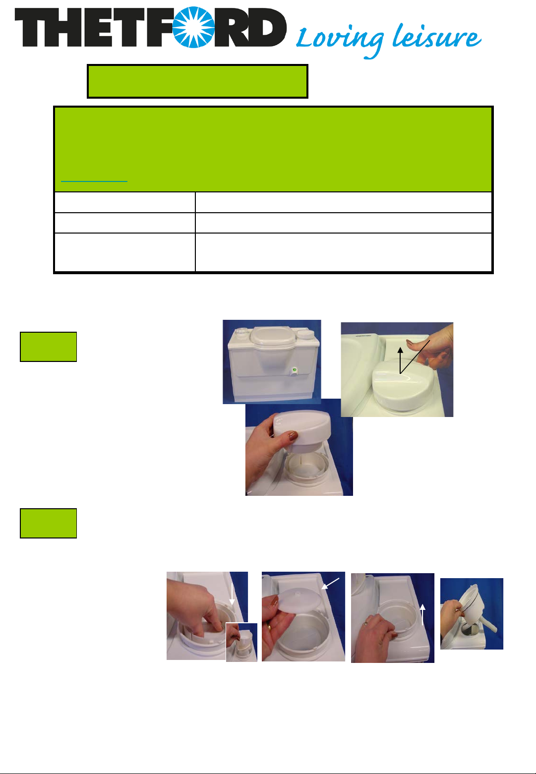
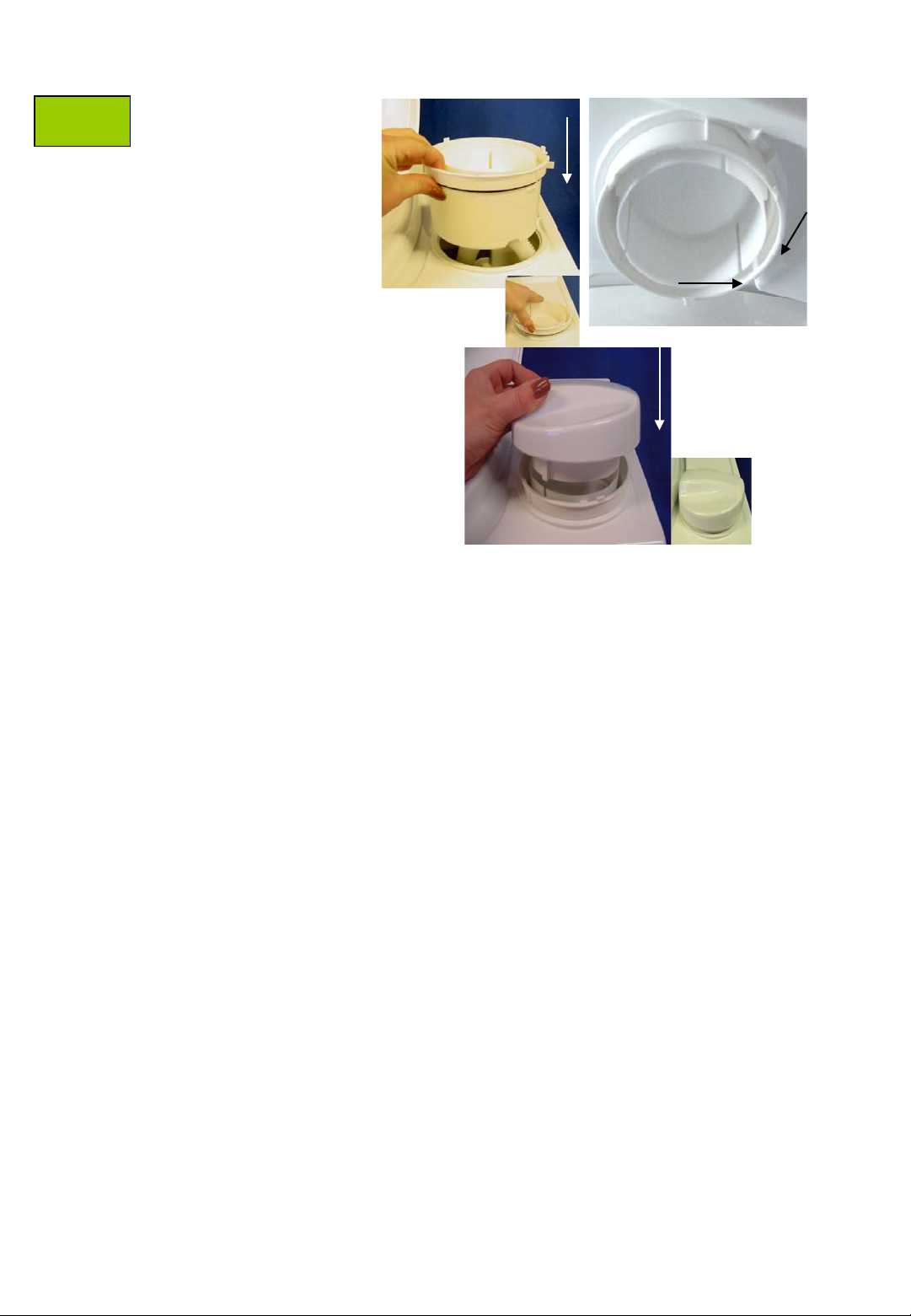
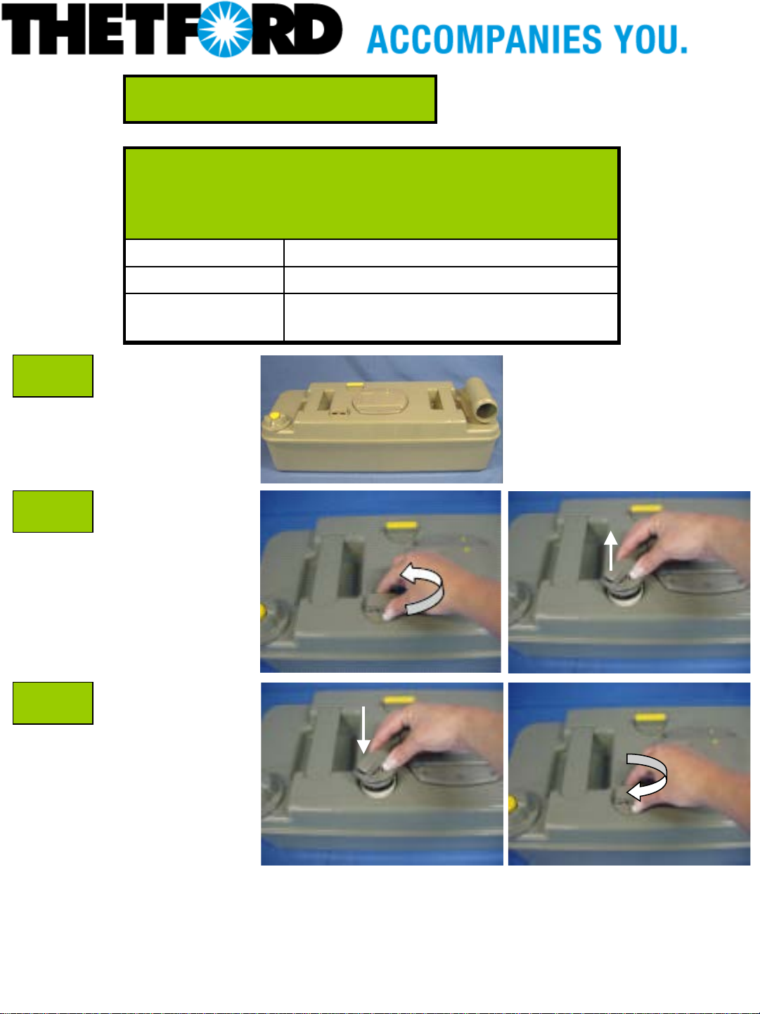
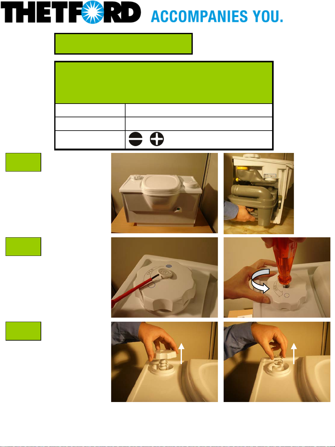
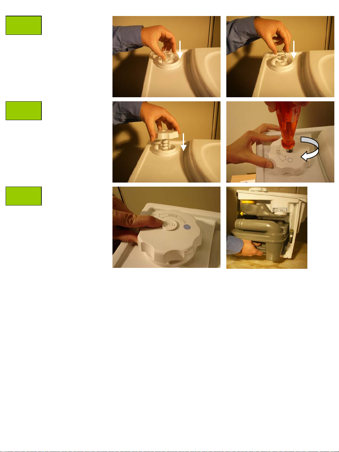
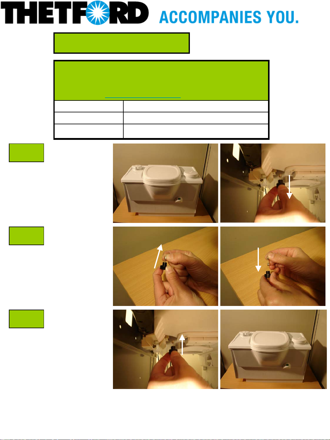
Lift the flush cap
up with your finger (1)
Push cylinder ( 2) dow n and turn it to
the left to take it out. After this,the
bellow cap (3) and housing (4) can be
taken out.
2.
1.
4.
3.
09/11 Description:Leaflet
21039
1
C
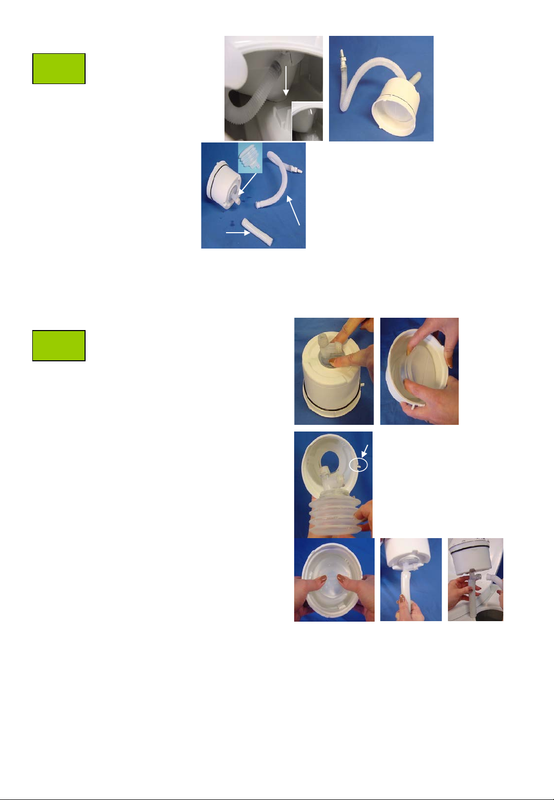
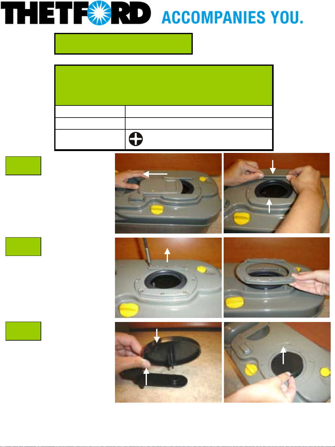
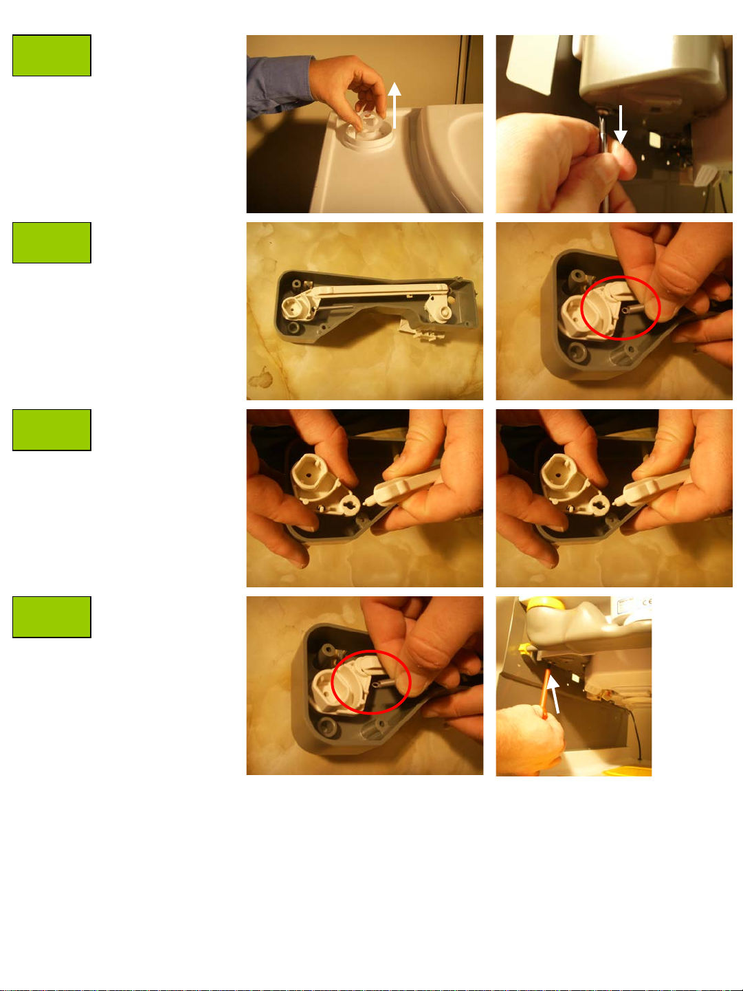
Inside view,
nozzle (5) has
to be taken out.
Can be pulled
down.
5.
6.
8.
7.
Lug
Inlet tube (6),
Flush tube (7) or
Bellow (8) can now
be replaced
Note : Inlet tube and Flush tube can easily be replaced by pulling of the part and press the new part on.
For replacing the Bellow see following instructions.
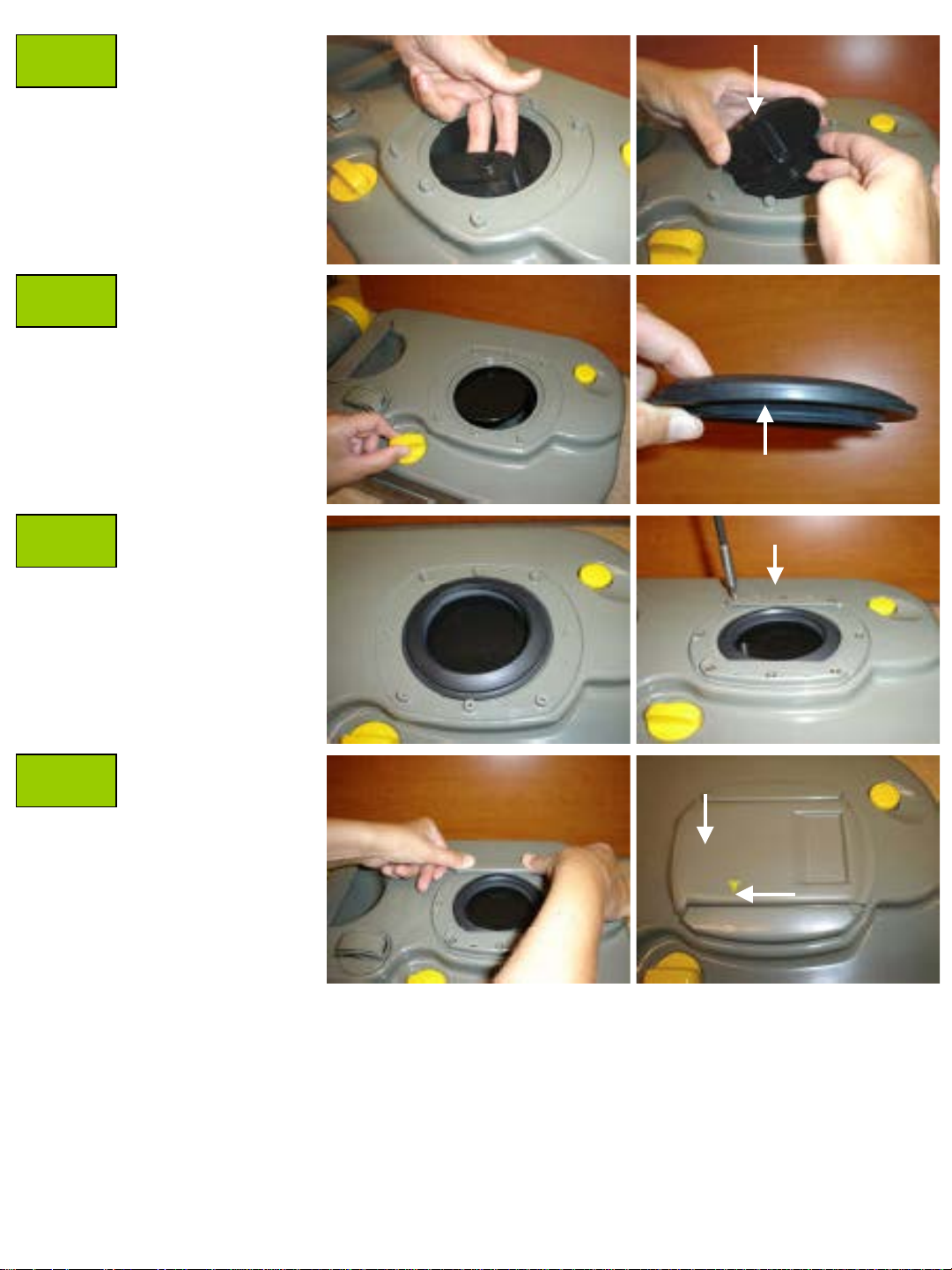
Bellow is fitted into the housing
D
with PTI (kind of kit). Depres s
bellowfirmly l oose (1) and pull it
out (2).
When placing the new bellow,
hold the parts in position as on
the
photo. Lug on t he housi ng has
to be on the right side.
Press the bellow into the
housing and, assemble inlet
tube and flush tube.
09/11 Description:Leaflet
21039
2
E
F
G
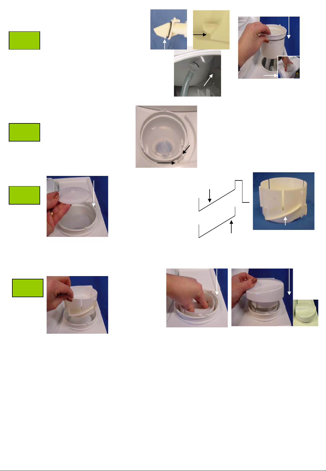
Bring nozzl e back into the hole
and press it up (you will hear a
click).Note :Rib on nozzle has
to go through the hole, to the
inside of the toilet bowl.
Turn the lug (1)
on the housing,
against the lug ( 2)
on the actual
Cassette toilet.
Cylinder can only
be pressed in one
way (single rib has
to face the backside
of the toilet).
2.
Rib
1.
2 x double rib
Rib inside
Toilet bowl
Push housing
in by hand
single rib
H
1 x single rib
Push the
cylinder
in
and turn
it to the
right.
09/11 Description:Leaflet
21039
3
2. 2029162 Flush mechanism
1.
A
B
C
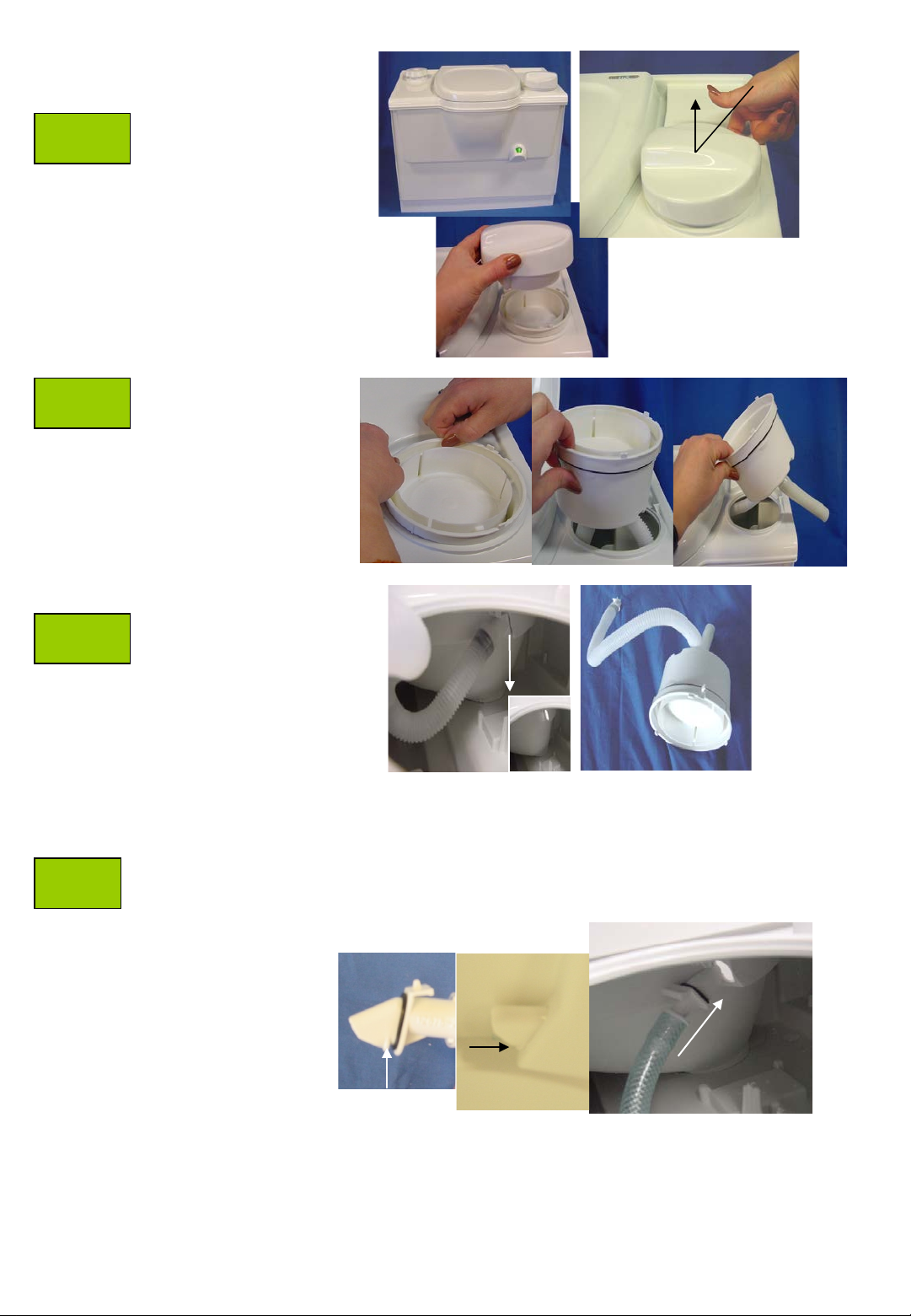
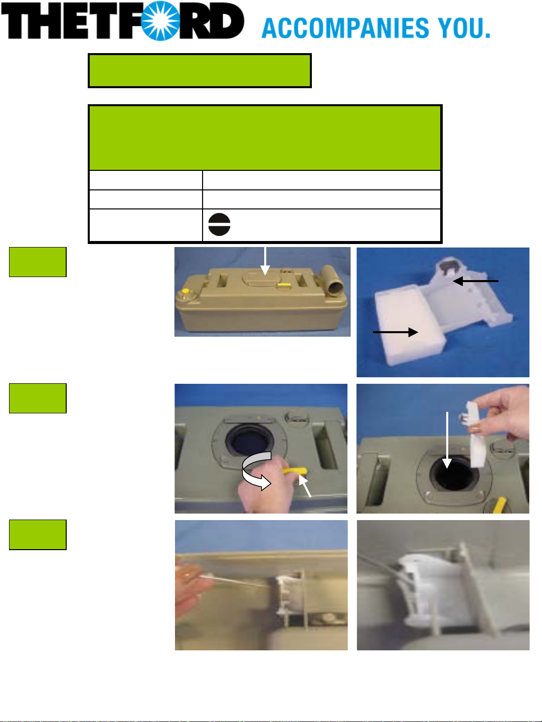
Lift the flush cap
up with your finger (1)
Flush mechanism
can be pulled out
by hand.
Inside view,
nozzle (2) has
to be taken out.
Can be pulled
down.
2.
Bring nozzl e from new flush mechanism bac k into
D
the hole and press it up (you will hear a click).
Note : Rib on nozzle has to go through the hole, to
the inside of the toilet bowl.
Rib inside
Rib
toilet bowl
09/11 Description:Leaflet
21039
4
E
Turn the lug (1)
on the housing,
against the lug ( 2)
on the actual
Cassette toilet.
1.
Push in
by hand
2.
09/11 Description:Leaflet
21039
5
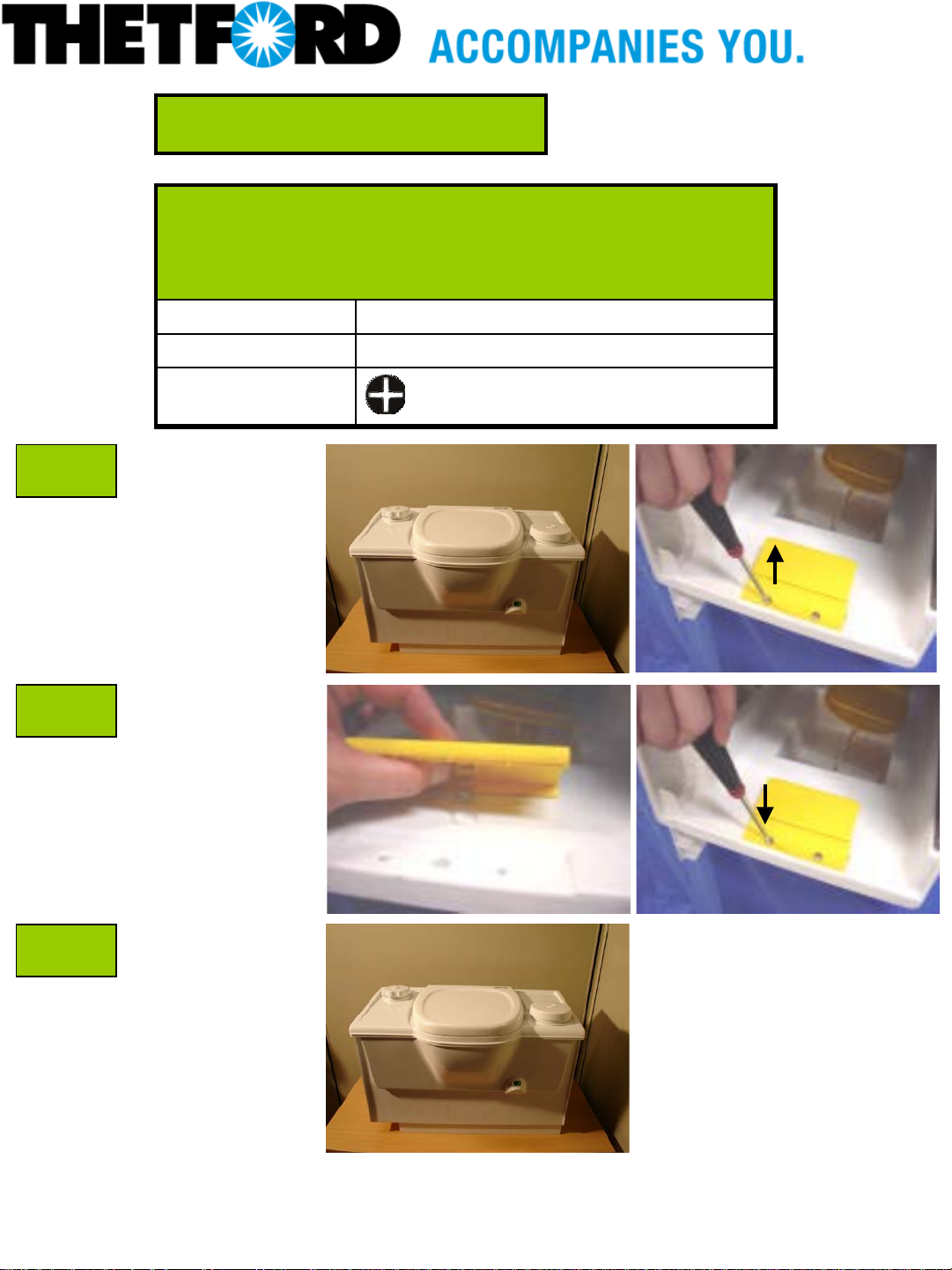
Repair instruction
Description: B lad e f use 3 Amp C2/C3 (toilets prod uced
after June 1994)
Part number: 21766
Look for Service Centers, Point of Sale addresses and other
information on: www.thetford-europe.com
Version: V2
Date: 13/07/2006
Tools required: -
A
B
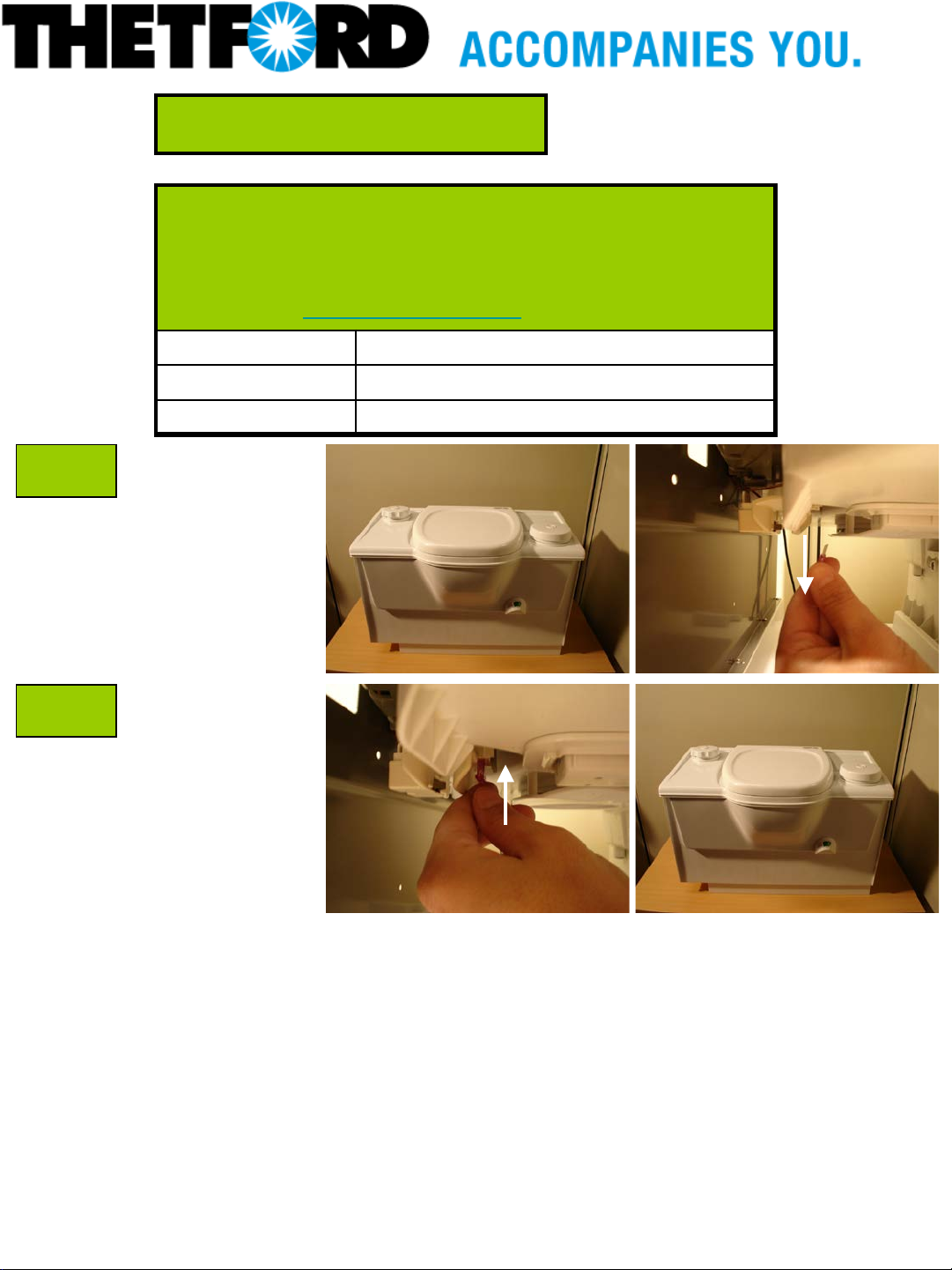
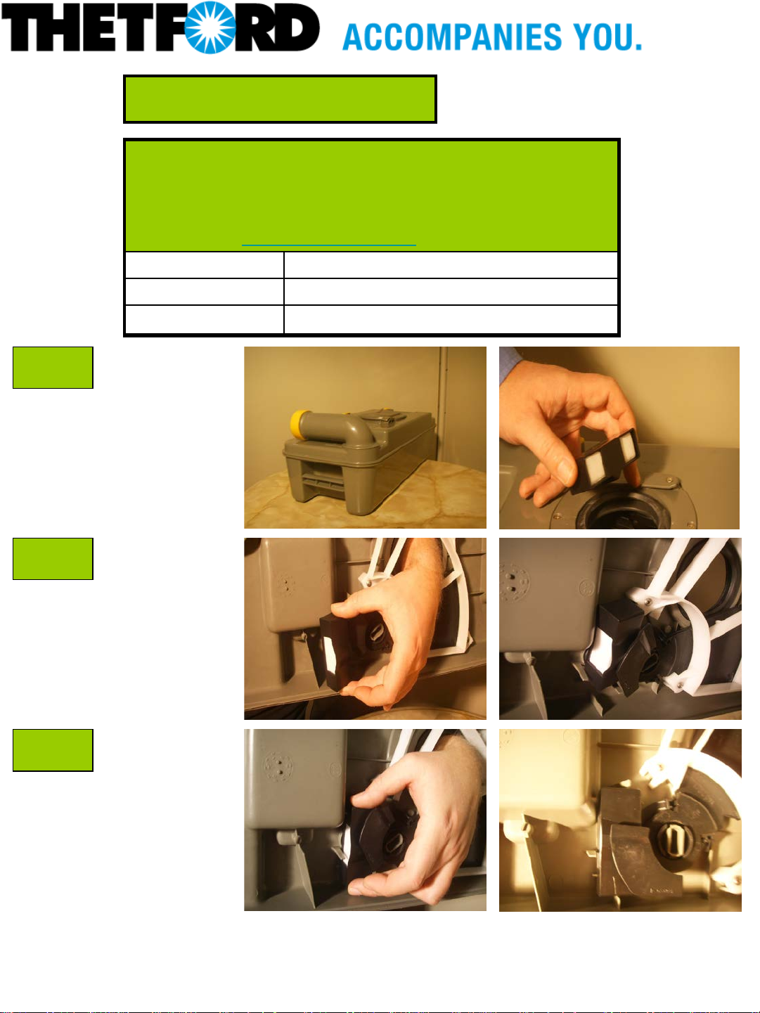
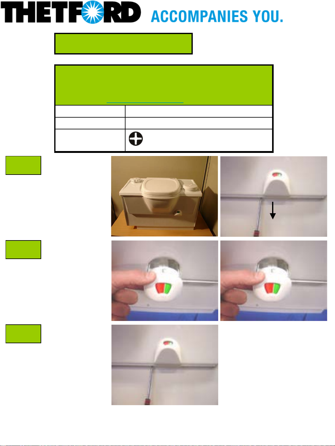
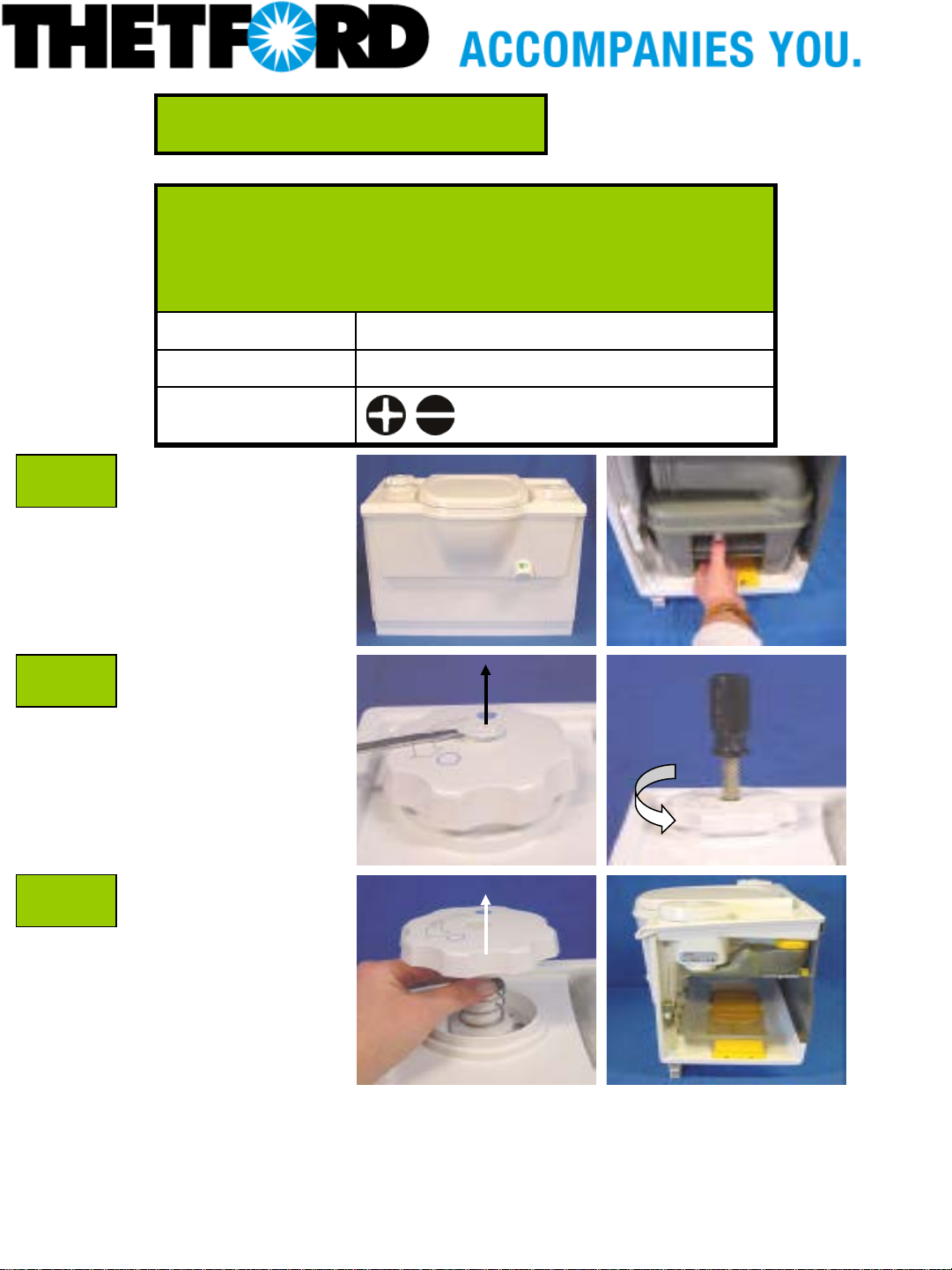
C2/C3 Toilet.
Pull the waste tank out
of the toilet by pushing
down the yellow clip.
Remove the blade
fuse.
Replace the new blade
fuse
Replace the waste tank
in the cassette.
13/07/2006 Description: Blade fuse 3
AMP C2/C3
1

Repair instruction
Description: C2 C3 (produced after June 1994) Blade fuse
3 amp
Part number: 21766
Look for Service Centers, Point of Sale addresses and other
information on: www.thetford-europe.com
Version: V2
Date: 13/07/2006
Tools required: -
A
B
C2/C3 Toilet.
Pull the waste tank out
of the toilet by pushing
down the yellow clip.
Remove the blade
fuse.
Replace the new blade
fuse
Replace the waste tank
in the cassette.
13/07/2006 Description: C2 C3
(produced after June
1994) Blade fuse 3 amp
1
Repair instruction
Description: C 2 C3 C4 ( p ro du ced after 15 Ju n e 2000) Lip
seal
Part number: 23721
Look for Service Centers, Point of Sale addresses and other
information on: www.thetford-europe.com
Version: V2
Date: 13/07/2006
Tools required:
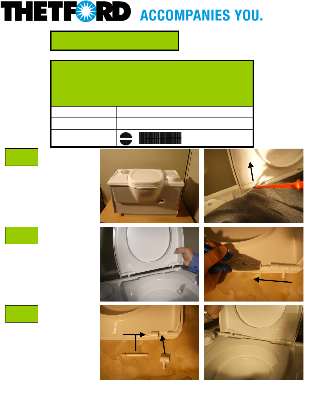
A
B
C
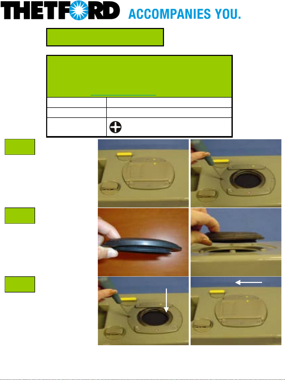
Remove the sliding
Cover.
Unscrew the 8 screws
on the seal cover and,
take the seal cover off.
Place new lip seal
on the waste tank.
Note: Thinner flange
has to face downwards
towards the blade.
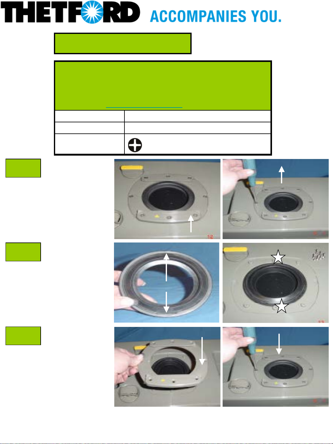
Place the lip seal on
the waste tank.
Screw the seal cover
back onto the waste
tank.
Sliding cover
Screw cover
Thinner flange
8x
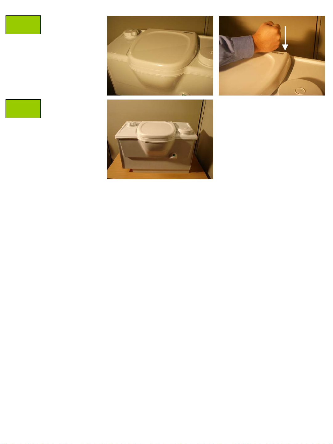
Place sliding cover
back on its place. Make
sure that the two
arrows are pointed to
each other.
13/07/2006 Description: C2 C3 C4
(produced after 15 June
2000) Lip seal
1

13/07/2006 Description: C2 C3 C4
(produced after 15 June
2000) Lip seal
2
Repair instruction
Description: C 2 C3 C4 ( p ro du ced until 15 June 2000) L ip
seal
Part number: 16175
Look for Service Centers, Point of Sale addresses and other
information on: www.thetford-europe.com
Version: V2
Date: 13/07/2006
Tools required:
A
B
C
Unscrew the 8 screws
on the seal cover and,
take the seal cover off.
Ensure the two cut outs
on the seal face
upwards and line up with
the two centre screws
of the three positioned
on either side of the seal
cover.
Replace the seat cover.
8x
Seal cover
Cut outs
8x
13/07/2006 Description: C2 C3 C4
(produced until 15 June
2000) Lip seal
1
Repair instruction
Description: C 2 C3 C4 C 200 Au t om at ic vent
Part number: 23722-74
Look for Service Centers, Point of Sale addresses and other
information on: www.thetford-europe.com
Version: V2
Date: 13/07/2006
Tools required: -
A
B
C
Holding tank
C2/C3/C4/C200
Turn the automatic vent
to the left and take it
out.
Place new automatic
vent in the waste tank
and turn it to the right
to lock it in the waste
tank.
13/07/2006 Description: C2 C3 C4
C200 Automatic Vent
1
Repair instruction
Description: C 2 C3 C4 C 200 B lad e
Part number: 23847
Look for Service Centers, Point of Sale addresses and other
information on: www.thetford-europe.com
Version: V2
Date: 13/06/2006
Tools required:
A
B
C
Remove the sliding
cover.
Remove the 2 screw
covers (only C200
toilets). Note: Lever off
gently.
Unscrew the 8 screws
on the seal cover.
Take the seal cover off.
General mechanism
info: do NOT remove
the blade arm when
changing the blade.
Screw cover
Sliding cover
Screw cover
8x
Blade
Pull the blade gently
out of the blade arm.
Note: the blade is
pressed into the blade
arm.
Blade arm
13/06/2006 Description: C2 C3 C4
C200 Blade
1
D
E
Push the blade arm a
little bit up.
Press the new blade
gently in the hole of the
blade arm.
Open and close the
blade a few times, to
ensure a good
operation of the
mechanism.
When placing the lip
seal on the waste tank,
the thinner flange has
to face downwards the
blade.
Thinner flange
F
G
Place the lip seal on
the waste tank.
Screw the seal cover
back onto the waste
tank.
Press both screw
covers back on the seal
cover (only C200
toilets).
Place sliding cover
back on its place. Make
sure that the two
arrows are pointed to
each other.
8x
Arrow
Arrow
13/06/2006 Description: C2 C3 C4
C200 Blade
2
Repair instruction
Description: C 2 C3 C4 F lo at arm
Part number: 21322 Float arm
Look for Service Centers, Point of Sale addresses and other
information on: www.thetford-europe.com
Version: V2
Date: 17/07/2006
Tools required:
A
B
C
Remove the sliding
cover.
Float arm is
assembled on the
opposite side of the
blade opener.
Open the blade.
The Magnet has to
point to the outside
of the waste tank.
Remove the float
retainer (if this is still
in the waste tank) by
placing the small flat
screwdriver between
the rib and the float
retainer and lift it up.
Sliding cover
Float retainer
Float arm
Blade opener
17/07/2006 Description: C2 C3 C4
Float arm
1
D
Place the new
float arm.
Place where float arm
has to be assembled
Place where float arm
has to be assembled
E
Press on the floatretainer.
17/07/2006 Description: C2 C3 C4
Float arm
2
Repair instruction
Description: C2 C3 C4 Float vent (produced before June
1993)
Part number: 21510
Look for Service Centres, Point of Sale addresses and other
information on: www.thetford-europe.com
Version: V1
Date: 17/01/2007
Tools required: -
A
B
C
Waste tank C2 C3
C4.
Enter the waste tank
with the float vent
ensuring the vent is
flat side up.
Position the float
vent as shown in the
picture.
Push the float vent
beneath the blade
arm driver.
17/01/2007 Description: C2 C3 C4
Float vent (produced
before June 1993)
1
Repair instruction
Description: C2 C3 C4 Flush knob
Part number: 16377
Look for Service Centres, Point of Sale addresses and other
information on: www.thetford-europe.com
Version: V1
Date: 17/01/2007
Tools required:
A
B
C
C2 C3 C4 toilet.
Pull the waste tank
out of the toilet by
pushing down on the
yellow clip.
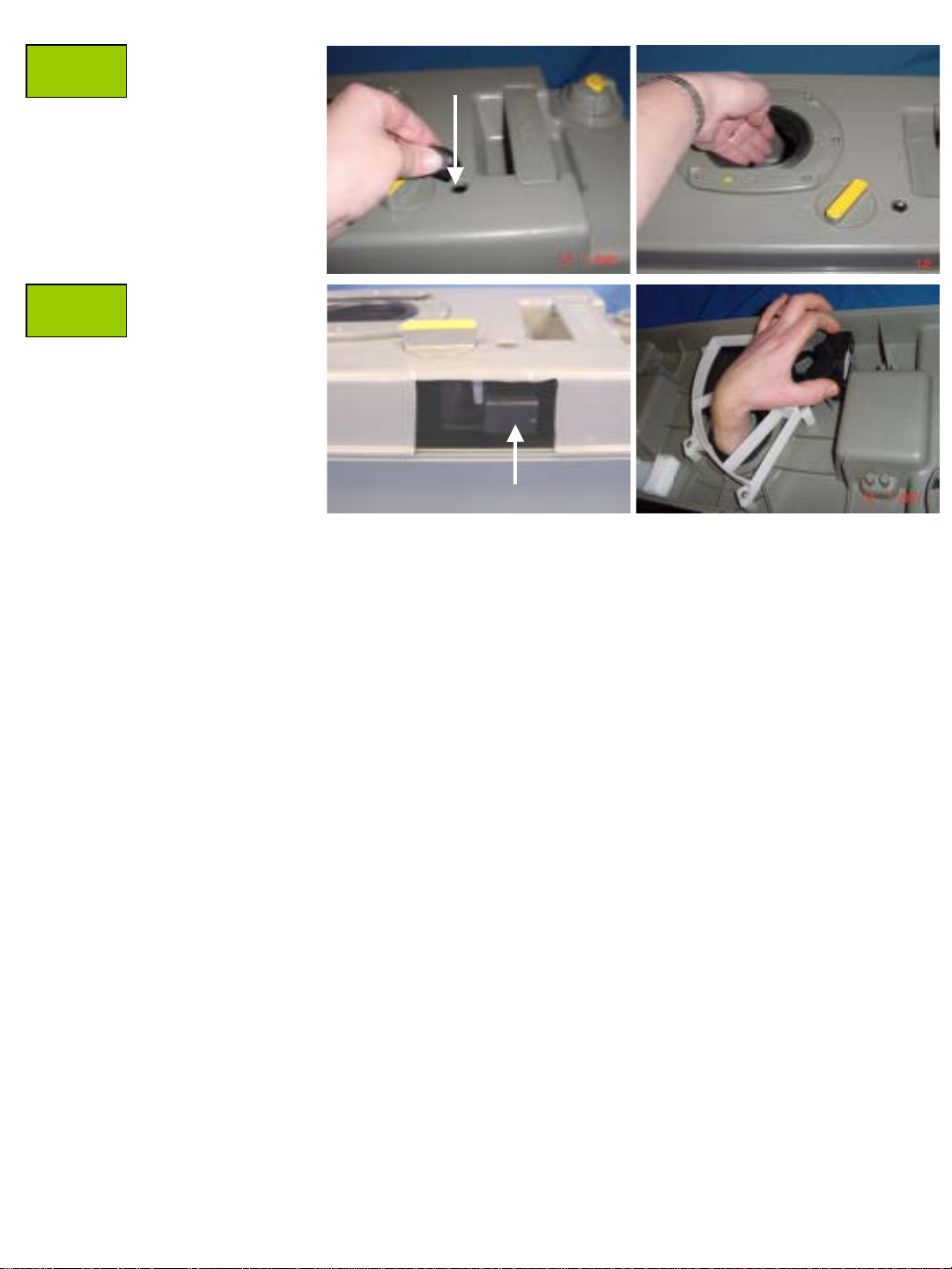
Remove the plug from
the flush knob with a
flat screwdriver.
Remove the screw in
the flush knob with a
long Philips
screwdriver.
Remove the flush
knob.
Remove the spring.
17/01/2007 Description: C2 C3 C4
Flush knob
1
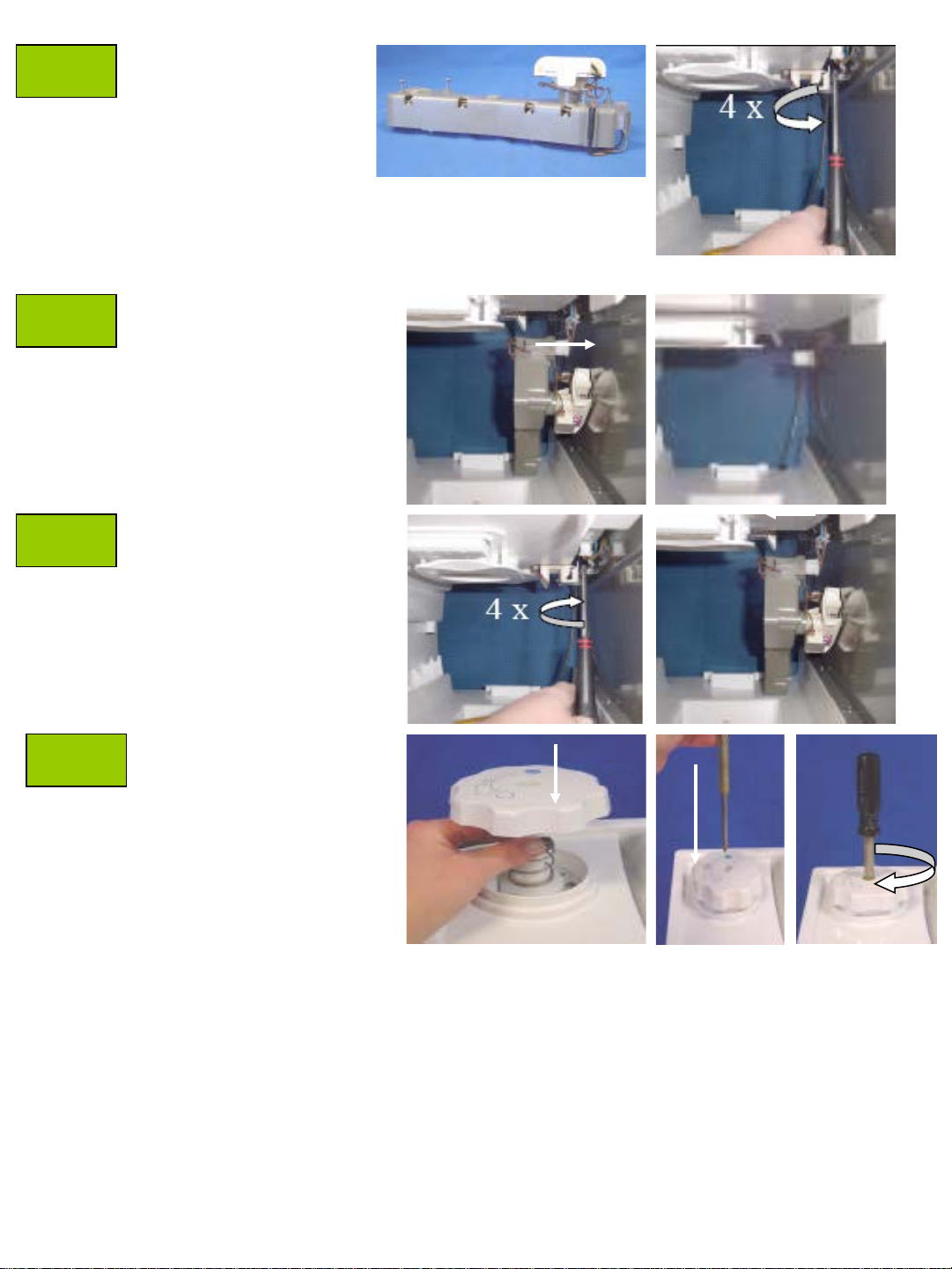
D
Remove the nylon
bushing.
4x.
From inside the toilet
remove the four
screws from the
mechanism
E
F
G
Mechanism overview.
Disconnect the spring.
Remove the crank.
Replace the new
crank.
Reconnect the spring.
Replace the four
screws from the
mechanism.
17/01/2007 Description: C2 C3 C4
Flush knob
4x.
2
H
Replace the new
nylon bushing.
Replace the new
spring.
I
J
Replace the new flush
knob.
Replace the screw in
the flush knob with a
long Philips
screwdriver.
Replace the plug from
the flush knob.
Replace the waste
tank back into the
toilet.
17/01/2007 Description: C2 C3 C4
Flush knob
3
Repair instruction
Description: C 2 C3 C4 L evel indicator
Part number: 16171-62
Look for Service Centers, Point of Sale addresses and other
information on: www.thetford-europe.com
Version: V2
Date: 13/07/2006
Tools required:
A
B
C
C2 C3 C4 toilet.
Unscrew the 7 screws
underneath the level
indicator
Replace the level
indicator
Screw the 7 screws
back into the toilet
13/07/2006 Description: C2 C3 C4
Level indicator
1
Repair instruction
Description: C2 C3 C4 Seat and cover/hinge pin and post
Part number: 16194 seat and cover 16183 hinge pin and
post
Look for Service Centres, Point of Sale addresses and other
information on: www.thetford-europe.com
Version: V1
Date: 17/01/2007
Tools required:
A
B
C
C2 C3 C4 toilet.
Lift the hinge post up
with a flat
screwdriver. Note:
protect the toilet
against damages
with a cloth.
Lift the seat and
cover up.
Pull out the two
hinge pins with the
pliers.
1. Position the new
hinge post.
2. Insert the new
hinge pin in place.
2.
Replace the seat
and cover.
1.
17/01/2007 Description: C2 C3 C4
Seat and cover/hinge pin
and post
1
D
E
Close the cover.
2X.
Firmly slam the seat
cover back into
position on both
hinge posts.
17/01/2007 Description: C2 C3 C4
Seat and cover/hinge pin
and post
2
Repair instruction
Description: C 2 C3 C4 Sp rin g clip retainer
Part number:16169/16 350 -78
Look for Service Centers, Point of Sale addresses and other
information on: www.thetford-europe.com
Version: V2
Date: 23/05/2006
Tools required:
A
B
C
C2/C3/C4 toilet.
Pull the waste tank out
of the toilet by lifting up
the yellow clip.
Unscrew the 2 screws
on the clip retainer,
replace spring or clip
+ clip retainer and
screw the 2 screws
back into the clip
retainer.
Replace the waste tank
In the cassette.
17/07/2006 Description: C2 C3 C4
Spring clip retainer
1
Repair instruction
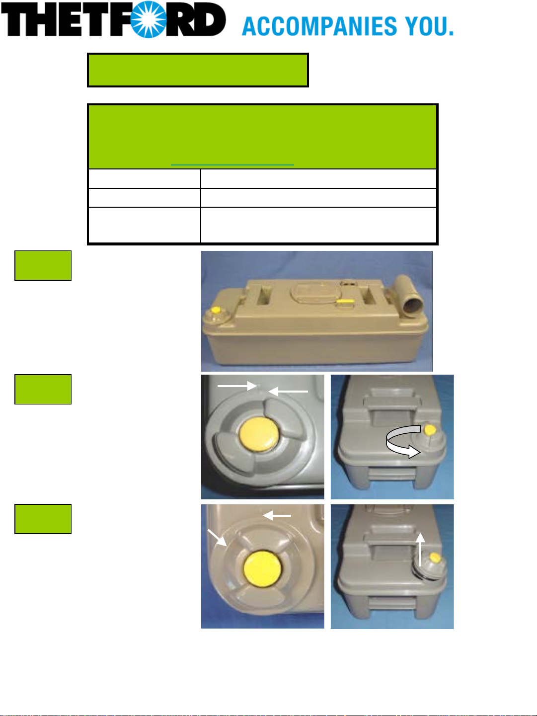
Description: C2 C3 C4 Vent plug Vent button
Part number: 16176-74 V ent plug 07524-78 Vent button
Look for Service Centers, Point of Sale addresses and other
information on: www.thetford-europe.com
Version: V1
Date: 29/05/2006
Tools required: -
A
B
C
Waste tank C2 C3 C4.
When the vent plug is
locked into the waste
tank, the two arrows (one
on the waste tank and
one on the vent plug) has
to be pointed to each
other.
Turn the vent plug away
from the arrow on the
waste tank ( can only be
turned one way) and lift
it up. Note : some force
may be needed to take
the vent plug out.
29/05/2006 Description:C2 C3 C4
V ent plug Vent button
1
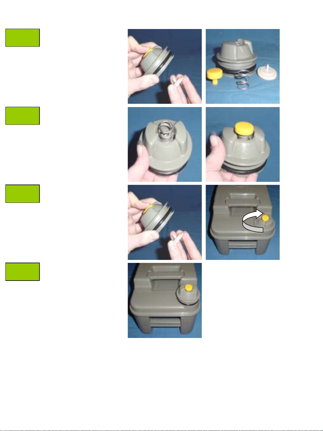
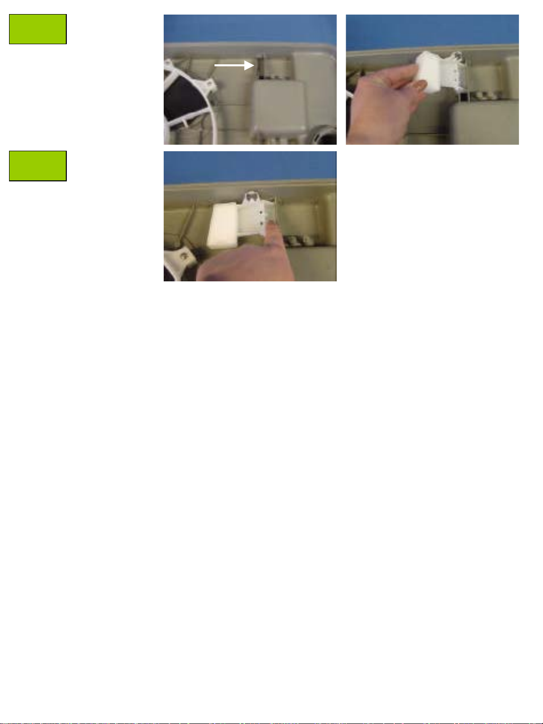
*Vent plug can now be replaced. If the vent button has to be replaced, please follow underneath instructions.
C
D
E
Press the vent button in
and pull the seal retainer
loose.
1. Vent plug
2. Vent button
3. Spring
4. Seal retainer
Place new spring and vent
button in the vent plug and
push the new seal
retainer in.
Note : Press the vent button
in while assembling the new
seal retainer.
2.
1.
4.
3.
Place vent plug back into the
waste tank and turn the two
arrows back to each other.
F
29/05/2006 Description:C2 C3 C4
V ent plug Vent button
2
Repair instruction
Description: C 2 C3 C4 Vent seal
Part number: 20339
Look for Service Centers, Point of Sale addresses and other
information on: www.thetford-europe.com
Version: V1
Date: 15/06/2006
Tools required:
A
B
C
Open the blade,
and depress the
vent seal (1) around
outer edge of seal
(1a).
Take the vent seal out
(2).
Bring new vent seal
on its place as shown.
Thinner flange has to
be on the float which
is
inside the waste tank.
1.
1A.
2.
Thinner flange Float
15/06/2006 Description: C2 C3 C4
V ent Seal
1
D
Depress the vent seal
through the hole, from
the outside. Note:
Make sure that the
vent seal is lying in
the middle of the hole,
when looking from the
top.
Go with your hand
in the waste tank.
E
press against the
float (vent seal will
be pressed into its
place).
Outside view:
float inside waste tank
Inside view: press against float
15/06/2006 Description: C2 C3 C4
V ent Seal
2
Repair instruction
Description: C 2 C3 Glass f u se 3 Amp
Part number: 16391
Look for Service Centers, Point of Sale addresses and other
information on: www.thetford-europe.com
Version: V1
Date: 08/05/2006
Tools required: -
A
B
C
C2/C3 Toilet.
Pull the waste tank
out of the toilet by
pushing down the
yellow clip.
Unscrew the cap fuse
holder.
Move the glass fuse
from the cap fuse
holder.
Place the new glass
fuse back into the cap
fuse holder.
Screw the cap fuse
holder back into the
toilet.
Replace the waste
tank in the cassette.
08/05/2006 Description: C2 C3
Glass Fuse 3 AMP
1
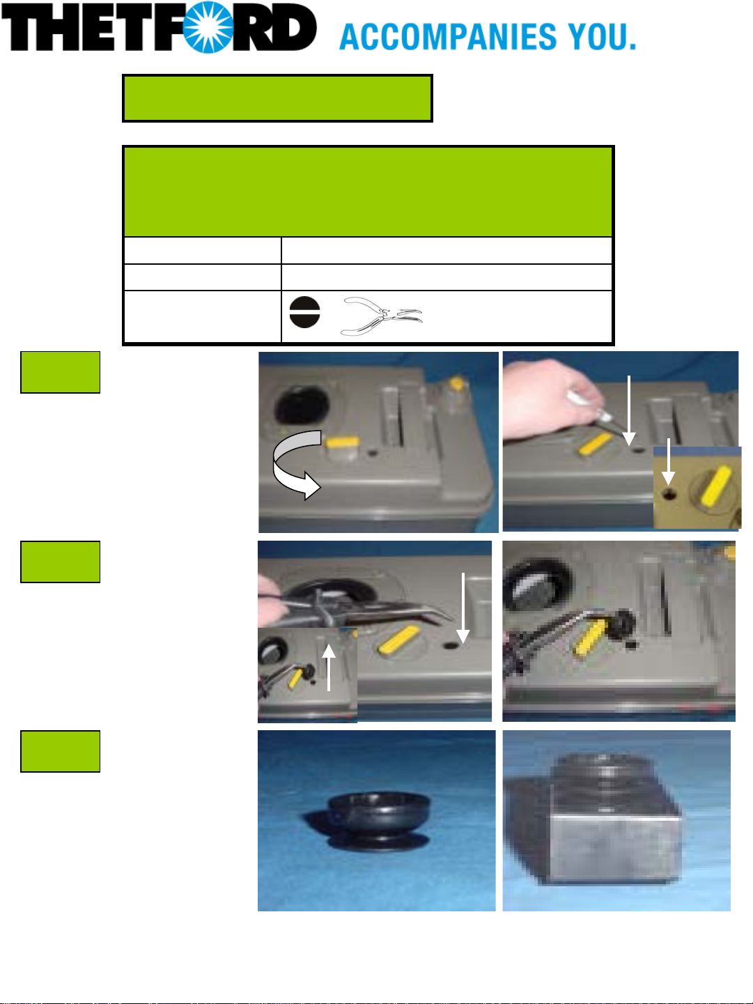
Repair instruction
Description: C2 C3 Mechanism
Part number: 16379-74
Look for Service Centers, Point of Sale addresses and other
information on: www.thetford-europe.com
Version: V1
Date: 05/05/2006
Tools required:
A
B
C
C2/C3 toilet.
Pull the waste tank out of
the Cassette toilet by lifting
up the yellow clip.
Place a flat screwdriver
under the small plastic
insert, which is in the
middle of the flush knob,
and take it off.
Unscrew the screw
inside the flush knob, with
a philips head screwdriver.
Complete flush knob can
be taken out now. After the
flush knob, the mechanism
housing has to be taken
out. Note : This can only
be done from the
outside.
When looking inside the
Cassette toilet from the
outside, the mechanism is
screwed to the underside
of the water tank.
Flush knob
05/05/2006 Description: Leaflet
20268
1
D
Mechanism housing which is
located inside the Cassette
toilet with four screws (on each
corner).
Remove the four screws
located on the mechanism,
allowing it to drop down. Note:
On Cassette toilets which are
produced between 1987 and
1989, 5 screws should be
removed.
4 x
F
G
H
Pull the white connector loose
from the mechanism, and press
the connector into the new
mechanism.
Screw the mechanism back on its
place.
Place the flush knob back
(in the same position as on the
photo, see print on the knob)
and, screw it back into the toilet
with the crosshead screwdriver.
05/05/2006 Description: Leaflet
20268
2
 Loading...