

Husqvarna 55R21HV B User Manual

55R21HV
Owner’s Manual
532 18 90-58 Rev. 1 03.16.04 BY
Printed in U.S.A.
For Parts and Service, call 1-800-448-7543

2
Safe Operation Practices for Walk-Behind Mowers
IMPORTANT: THIS CUTTING MACHINE IS CAPABLE OF AMPUTATING HANDS AND FEET AND THROW ING OBJECTS. FAILURE
TO OBSERVE THE FOLLOWING SAFETY INSTRUCTIONS COULD RESULT IN SERIOUS INJURY OR DEATH.
SAFETY RULES
I. GENERAL OPERATION
• Read, understand, and follow all instructions on the
machine and in the manual(s) before starting. Be thor-
ough ly familiar with the controls and the proper use of
the machine before starting.
• Do not put hands or feet near or under rotating parts.
Keep clear of the discharge opening at all times.
• Only allow responsible individuals, who are familiar
with the instructions, to operate the machine.
• Clear the area of objects such as rocks, toys, wire,
bones, sticks, etc., which could be picked up and thrown
by the blade.
• Be sure the area is clear of other people before mow-
ing. Stop machine if anyone enters the area.
• Do not operate the mower when barefoot or wearing
open sandals. Always wear substantial foot wear.
• Do not pull mower backwards unless absolutely nec-
es sary. Always look down and behind before and while
moving backwards.
• Do not operate the mower without proper guards,
plates, grass catcher or other safety protective devices
in place.
• See manufacturer’s instructions for proper operation
and installation of accessories. Only use accessories
approved by the manufacturer.
• Stop the blade(s) when crossing gravel drives, walks,
or roads.
• Stop the engine (motor) whenever you leave the equip-
ment, before cleaning the mower or unclogging the
chute.
• Shut the engine (motor) off and wait until the blade comes
to complete stop before removing grass catch er.
• Mow only in daylight or good artifi cial light.
• Do not operate the machine while under the infl uence
of alcohol or drugs.
• Never operate machine in wet grass. Always be sure of
your footing: keep a fi rm hold on the handle and walk;
never run.
• Disengage the self-propelled mechanism or drive clutch
on mowers so equipped before starting the engine (mo-
tor).
• If the equipment should start to vibrate abnormally,
stop the engine (motor) and check immediately for the
cause. Vibration is generally a warning of trouble.
• Always wear safety goggles or safety glasses with side
shields when operating mower.
II. SLOPE OPERATION
Slopes are a major factor related to slip and fall accidents
which can result in severe injury. All slopes require extra
caution. If you feel uneasy on a slope, do not mow it.
DO:
• Mow across the face of slopes: never up and down. Exer-
cise extreme caution when changing direction on slopes.
• Remove obstacles such as rocks, tree limbs, etc.
• Watch for holes, ruts, or bumps. Tall grass can hide
obstacles.
DO NOT:
• Do not trim near drop-offs, ditches or embankments.
The operator could lose footing or balance.
• Do not trim excessively steep slopes.
• Do not mow on wet grass. Reduced footing could cause
slipping.
III. CHILDREN
Tragic accidents can occur if the operator is not alert to
the presence of children. Children are often attracted to
the machine and the mowing activity.
Never
assume that
children will remain where you last saw them.
• Keep children out of the trimming area and under the
watchful care of another re spon si ble adult.
• Be alert and turn machine off if children enter the
area.
• Before and while walking backwards, look behind and
down
for small children.
• Never allow children to operate the machine.
• Use extra care when approaching blind corners, shrubs,
trees, or other objects that may obscure vision.
IV. SERVICE
• Use extra care in handling gasoline and other fuels.
They are fl ammable and vapors are explosive.
- Use only an approved container.
- Never remove gas cap or add fuel with the
engine running. Allow engine to cool before
refueling. Do not smoke.
- Never refuel the machine indoors.
- Never store the machine or fuel container inside
where there is an open fl ame, such as a water
heater.
• Never run a machine inside a closed area.
• Never make adjustments or repairs with the engine
(motor) running. Disconnect the spark plug wire, and
keep the wire away from the plug to prevent accidental
starting.
• Keep nuts and bolts, especially blade attachement
bolts, tight and keep equipment in good condition.
• Never tamper with safety devices. Check their proper
operation regularly.
• Keep machine free of grass, leaves, or other debris
build-up. Clean oil or fuel spillage. Allow machine to
cool before storing.
• Stop and inspect the equipment if you strike an object.
Repair, if necessary, before restarting.
• Never attempt to make wheel height adjustments while
the engine (motor) is running.
• Grass catcher components are subject to wear, dam-
age, and deterioration, which could expose moving
parts or allow objects to be thrown. Frequently check
com po nents and replace with manufacturer’s rec om -
mend ed parts, when necessary.
• Mower blades are sharp and can cut. Wrap the blade(s)
or wear gloves, and use extra caution when servicing
them.
• Do not change the engine governor setting or overspeed
the engine.

3
PRODUCT SPECIFICATIONS
Gasoline Capacity 1.0 Quarts
and Type: (Unleaded Regular Only)
Oil Type (API-SF-SJ): SAE 10W-30
Oil Capacity: 18.5 Ounces
Spark Plug: NGK BPR6ES (Gap: .030")
Valve Clearance: Intake: 0.015 mm
(± 0.04 mm) Exhaust: 0.020 mm
Blade Bolt Torque: 35-40 ft. lbs.
CONGRATULATIONS on your purchase of a new lawn
mower. It has been designed, engineered and man u fac tured
to give you the best possible dependability and performance.
Should you experience any problem you cannot easily
remedy, please contact your nearest authorized service
center/department. We have competent, well-trained
tech ni cians and the proper tools to service or repair this
lawn mower.
Please read and retain this manual. The instructions will
enable you to assemble and maintain your lawn mower
properly. Always observe the “SAFETY RULES”.
SERIAL
NUMBER: _________________________________
DATE OF PURCHASE: _______________________
THE MODEL AND SERIAL NUMBERS WILL BE FOUND
ON A DECAL ATTACHED TO THE REAR OF THE LAWN
MOWER HOUSING.
YOU SHOULD RECORD BOTH SERIAL NUMBER AND
DATE OF PURCHASE AND KEEP IN A SAFE PLACE
FOR FUTURE REFERENCE.
CUSTOMER RESPONSIBILITIES
• Read and observe the safety rules.
• Follow a regular schedule in maintaining, caring for and
using your lawn mower.
• Follow the instructions under “Maintenance” and “Stor-
age” sec tions of this own er’s manual.
TABLE OF CONTENTS
SAFETY RULES ......................................................... 2-3
PRODUCT SPECIFICATIONS....................................... 3
CUSTOMER RESPONSIBILITIES................................. 3
ASSEMBLY................................................................. 4-5
OPERATION ............................................................. 6-10
MAINTENANCE SCHEDULE ...................................... 11
MAINTENANCE...................................................... 11-13
SERVICE AND AD JUST MENTS ............................ 13-15
STORAGE ............................................................... 15-16
TROU BLE SHOOT ING ................................................. 17
REPAIR PARTS....................................................... 18-23
WARRANTY................................................................. 24
WARNING: Battery posts, terminals and
related ac ces so ries contain lead and
lead compounds, chemicals known to
the State of Cal i for nia to cause can cer
and birth defects or oth er re pro duc tive
harm. Wash hands after handling.
WARNING: Engine exhaust, some of
its con stit u ents, and certain vehicle
com po nents contain or emit chem i-
cals known to the State of Cal i for nia
to cause can cer and birth defects or
oth er re pro duc tive harm.
CAUTION: Always disconnect spark plug
wire and place wire where it cannot contact
spark plug in order to prevent ac ci den tal
starting when setting up, trans port ing,
adjusting or making re pairs.
Look for this symbol to point out im-
por tant safety precautions. It means
CAUTION!!! BE COME ALERT!!! YOUR
SAFE TY IS IN VOLVED.
CAUTION: Muffl er and other engine
parts become extremely hot during
operation and remain hot after engine
has stopped. To avoid severe burns on
contact, stay away from these areas.

4
ASSEMBLY
Read these instructions and this man u al in its entirety before
you attempt to assemble or operate your new lawn mow er.
IMPORTANT: THIS LAWN MOWER IS SHIPPED WITH-
OUT OIL OR GASOLINE IN THE ENGINE.
Your new lawn mower has been as sem bled at the factory
with the ex cep tion of those parts left unassembled for ship-
ping purposes. All parts such as nuts, washers, bolts, etc.,
necessary to com plete the as sem bly have been placed in
the parts bag. To ensure safe and proper operation of your
lawn mow er, all parts and hard ware you assemble must
be tightened se cure ly. Use the correct tools as nec es sary
to ensure proper tightness.
TO RE MOVE LAWN MOW ER FROM CAR TON
1. Remove loose parts included with mower.
2. Cut down two end corners of car ton and lay end panel
down fl at.
3. Remove all packing materials ex cept padding be tween
upper and lower handle and padding holding operator
presence control bar to up per handle.
4. Roll lawn mower out of carton and check carton thor-
ougly for ad di tion al loose parts.
HOW TO SET UP YOUR LAWN MOW ER
TO UNFOLD HANDLE (See Figs. 1 and 2)
IMPORTANT: UNFOLD HANDLE CAREFULLY SO AS
NOT TO PINCH OR DAMAGE CON TROL CABLES.
1. Raise lower handle to operating position and align hole
in handle with one of the height positioning holes in
the handle bracket.
2. Insert handle bolt through handle and bracket and
secure with knob.
3. Repeat for opposite side of handle.
4. Remove protective padding, raise upper handle sec-
tion into place on lower handle and tighten both handle
knobs.
5. Remove packing material from around control bar.
Your handles may be adjusted for your mowing comfort.
Refer to “ADJUST HANDLE” in the Service and Ad just ments
sec tion of this man u al.
FIG. 1
OPERATOR PRESENCE
CONTROL BAR
UPPER HANDLE
LIFT
UP
LIFT UP
LOWER HANDLE
MOWING
PO SI TION
FIG. 2
HANDLE
BRACKET
KNOB
BOLT
5
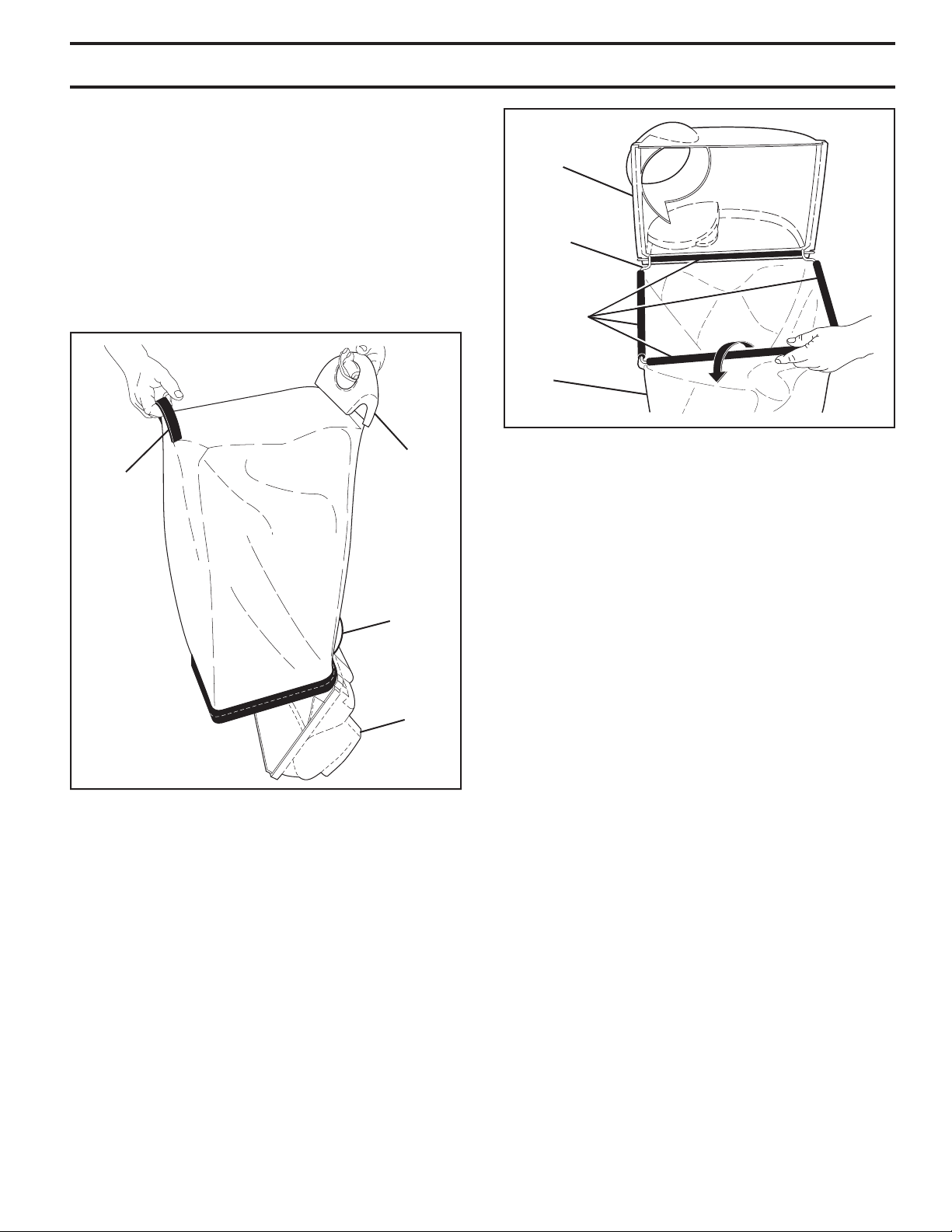
TO ASSEMBLE GRASS CATCHER
(See Figs. 3 and 4)
1. Slide grass catcher bag over the frame. Make sure
the rear handle is on top (the same side as the front
handle) and the strap is on the bottom.
2. Slip vinyl bindings over frame.
NOTE: If vinyl bindings are too stiff, hold them in warm water
for a few minutes. If bag gets wet, let it dry before using.
3. Close grass catcher door.
NOTE: When fully closed, door will “snap” shut over frame
and vinyl bindings.
TO INSTALL ATTACHMENTS
Your lawn mower was shipped ready to be used as a
mulcher. To convert mower to bagging or discharging,
see “TO CON VERT MOWER” in the Operation section of
this man u al.
GRASS
CATCHER
FRAME
FIG. 4
VINYL
BINDINGS
DOOR
BAG
ASSEMBLY
FIG. 3
FRONT
HANDLE
REAR
HANDLE
STRAP
DOOR
6
KNOW YOUR LAWN MOWER
READ THIS OWNER'S MANUAL AND SAFETY RULES BEFORE OPERATING YOUR LAWN MOWER.
Compare the illustrations with your lawn mower to familiarize yourself with the location of various controls and adjustments.
Save this manual for future reference.
MEETS CPSC SAFETY REQUIREMENTS
Our rotary walk-behind power lawn mowers conform to the safety standards of the American National Standards Institute
and the U.S. Consumer Product Safety Commission. The blade turns when the engine is running.
OPERATOR PRESENCE CONTROL BAR - must be held
down to the handle to start engine. Release to stop engine.
MULCHER DOOR - allows conversion to discharge or
bagging operation.
STARTER HANDLE - used for starting the engine.
HOUSING
GRASS
CATCHER
DRIVE CONTROL LEVER - used to engage power-pro-
pelled forward motion lawn mower.
DUAL POINT HEIGHT ADJUSTER – used to adjust cutting
height of lawn mower.
OPERATOR PRESENCE CON TROL BAR
STARTER
HANDLE
EN GINE OIL CAP
WITH DIPSTICK
HANDLE
KNOB
GAS O LINE FILL ER CAP
These symbols may appear on your lawn mower or in literature supplied with the product. Learn and understand
their meaning.
MULCHER DOOR
OPERATION
IMPORTANT: This lawn mower is shipped
WITHOUT OIL OR GASOLINE in the engine.
FUEL VALVE LEVER
DRIVE CONTROL LEVER
DRIVE COVER
MUFFLER
DUAL POINT HEIGHT
ADJUSTER LEVER
AIR FILTER

7
2. Pull out button on underside of drive control, then push
it back in.
3. Operate mower to test drive speed. If there is no in-
crease, your drive belt is worn and should be re placed.
TO ADJUST CUTTING HEIGHT (See Fig. 6)
Both front wheels are adjusted by a single lever on the left
front wheel. Likewise, both rear wheels are adjusted by a
single lever on the left rear wheel.
• Pull adjuster lever toward wheel. To raise mower, move
lever forward to desired position. To lower mow er, move
the lever toward the rear.
Be sure to adjust both front and rear wheels to same height.
HOW TO USE YOUR LAWN MOWER
ENGINE SPEED
The engine speed was set at the factory for optimum per-
formance. Speed is not adjustable.
ENGINE ZONE CONTROL
CAUTION: Federal regulations require
an engine control to be installed on this
lawn mower in order to minimize the risk
of blade contact injury. Do not un der
any cir cum stanc es attempt to defeat
the function of the operator control.
The blade turns when the engine is
running.
• Your lawn mower is equipped with an operator presence
control bar which requires the operator to be positioned
behind the lawn mower handle to start and operate the
lawn mower.
DRIVE CONTROL (See Fig. 5)
• Self-propelling is controlled by hold ing the operator
presence control bar down to the handle and pulling
the drive control lever rearward to the handle. The
farther toward the handle the lever is pulled, the faster
the unit will travel.
• Forward motion will stop when either the operator pres-
ence control bar or drive control lever are released. To
stop forward motion without stop ping engine, re lease
the drive control lever only. Hold op er a tor presence
control bar down against handle to con tin ue mowing
without self-propelling.
NOTE: If after releasing the drive control the mower will
not roll backwards, push the mower forward slightly to
disengage drive wheels.
The operation of any lawn mower can result in foreign objects thrown into the eyes, which can result
in severe eye damage. Always wear safety glasses or eye shields while operating your lawn mower or
performing any adjustments or repairs. We recommend standard safety glasses or a wide vision safety
mask over spectacles.
OPERATION
FIG. 6
LEVER BACKWARD
TO LOWER MOWER
LEVER FORWARD
TO RAISE MOWER
HEIGHT
ADJUSTER
LEVER
FIG. 5
TO ENGAGE
DRIVE
CONTROL
DRIVE
CONTROL
LEVER
DRIVE
CONTROL
DISENGAGED
OPERATOR PRESENCE CONTROL BAR
ADJUSTMENT
BUTTON (ON
UNDERSIDE)
DRIVE CONTROL ADJUSTMENT (See Fig. 5)
Over time, the drive control system may become “loose”,
resulting in decreased speed. There is a button on the
un der side of the drive control housing to increase tension
on the drive cable. Pro ceed as follows:
1. Turn unit off and disconnect spark plug wire from plug.
TO CONVERT MOWER (See Figs. 7 thru 9)
Your lawn mower was shipped ready to be used as a mulcher.
To convert to rear bagging or side discharging:
REAR BAGGING
• Remove knob securing mulcher door to mower housing.
• Open mulcher door and insert tabs of discharge chute
into hinge bracket opening and position rear of chute
over threaded stud.
FIG. 7
DISCHARGE CHUTE TABS
HINGE BRACKET MULCHER DOOR
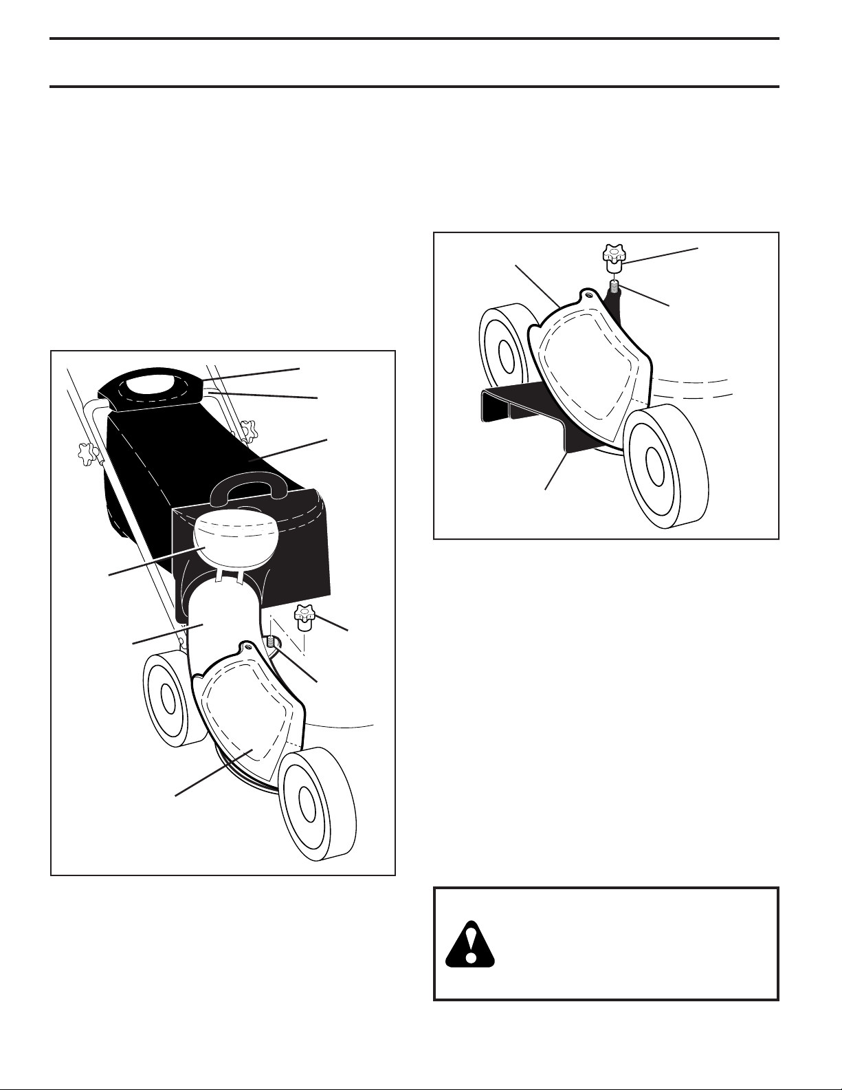
8
OPERATION
• Secure rear of discharge chute to lawn mower housing
with knob.
• Place rear handle of grass catcher on the crossbar of
the lawn mower's lower handle as shown.
• Lift the round door of the discharge chute and place
the grass catcher into place on the discharge chute.
NOTE: Be sure round door of discharge chute rests on
grass catcher as shown.
• Mower is now ready for rear bagging operation.
• To convert to mulching operation, remove grass catch er
and discharge chute. Secure mulcher door to mower
housing with knob.
• To convert to side dis charg ing operation, remove grass
catch er and discharge chute. Install side discharge
defl ector and secure it to mower housing with knob.
SIMPLE STEPS TO REMEMBER WHEN
CONVERTING YOUR LAWN MOWER
FOR MULCHING -
1. Grass catcher, discharge chute and side discharge
defl ector removed.
2. Mulcher door secured to mower housing with knob.
FOR REAR BAGGING -
1. Side discharge defl ector removed.
2. Grass catcher and discharge chute installed with
discharge chute secured to lawn mower housing with
knob.
3. Round door of discharge chute resting on top of grass
catcher.
FOR SIDE DISCHARGING -
1. Grass catcher and discharge chute removed.
2. Side discharge defl ector installed and secured to mower
housing with knob.
CAUTION: Do not run your lawn mower
with out mulcher door closed; side dis-
charge defl ector installed, or discharge
chute and ap proved grass catcher in
place. Never at tempt to op er ate the lawn
mow er with mulcher door or round door
re moved or propped open.
SIDE DISCHARGING
• Grass catcher and discharge chute must be re-
moved.
• Open mulcher door and install front of side dis charge
defl ector beneath it as shown.
• Secure rear of side discharge defl ector to lawn mower
housing with knob.
FIG. 8
DISCHARGE
CHUTE
ROUND
DOOR
GRASS
CATCHER
CROSSBAR
MULCHER
DOOR
KNOB
REAR HANDLE
THREADED
STUD
• Mower is now ready for side discharging operation.
• To convert to mulching operation, side dis charge de-
fl ector must be removed and mulcher door secured to
mower housing with knob.
• To convert to rear bagging operation, side discharge
defl ector must be removed; discharge chute and grass
catcher installed and discharge chute secured to mower
housing with knob.
FIG. 9
SIDE
DISCHARGE
DEFLECTOR
KNOBMULCHER
DOOR
THREADED
STUD
 Loading...