

Page 1

Operator’s Manual
Models
521SSE
521SSR
16
Read and keep this book for future reference.
This book contains important information on
SAFETY, ASSEMBLY, OPERATION, AND MAINTENANCE.
PRODUCT INFORMATION
The owner must be certain that all the
product information is included with the unit.
This information includes the INSTRUCTION
BOOKS, the REPLACEMENT PARTS and the WARRANTIES.
This information must be included to make sure state laws and
other laws are followed.
1740274 TP 100-4350-01-SW-R
Page 2

INTRODUCTION
Congratulations on your purchase. This Snowthrower has been designed, engineered and manufactured to give you the best
possible dependability and performance. However, like all mechanical products, your machine will occasionally require adjustment and maintenance. This handbook should be read before operating or performing and adjustments on your machine.
The instructions in this Owner’s Manual are written for a person with some mechanical ability. Like most service books, not
all the steps are described. Steps on how to loosen or tighten fasteners are steps anyone can follow with some mechanical
ability. Read and follow these instructions before you use the unit.
Know your product:: If you understand the unit and how the unit operates, you will get the best performance. As you read
this manual, compare the illustrations to the unit. Learn the location and the function of the controls. To help prevent an accident, follow the operating instructions and the safety rules. Keep this manual for future reference.
IMPORTANT: Many units are not assembled and are sold in cartons. It is the responsibility of the owner to make sure the as-
sembly instructions in this manual are exactly followed. Other units are purchased in an assembled condition. On assembled
units, it is the responsibility of the owner to make sure the unit is correctly assembled. The owner must carefully check the unit
according to the instructions in this manual before it is first used.
The warranty, found in this manual, details the coverage and limitations of this product.
RESPONSIBILITY OF THE OWNER
It is the responsibility of the owner to follow the instructions below.
1. Carefully read and follow the rules for safe operation.
2. Follow all the assembly instructions.
3. Inspect the unit.
4. Make sure that the operator of the unit knows how to correctly use all standard and accessory equipment.
5. Operate the unit only with guards, shields, and other safety items in place and working correctly.
6. Correctly adjust the unit.
7. Service the unit only with authorized or approved replacement parts.
8. Complete all maintenance on the unit.
FOR YOUR RECORDS
DATE PURCHASED:
MODEL NO:
SERIAL NO:
STORE WHERE PURCHASED:
1740274
ADDRESS:
CITY: STATE:
TELEPHONE :
Record this information about your unit so that you will
be able to provide it in case of loss or theft.
2
Page 3

RULES FOR SAFE OPERATION
This manual contains safety information to
make you aware of the hazards and risks
associated with snow throwers, and how to avoid them.
The snow thrower is designed and intended for removal
of snow, and should not be used for any other purpose. It
is important that you read and understand these
instructions, and anyone operating the equipment read
and understand these instructions.
WARNING
The engine exhaust from this product contains chemicals
known to the State of California to cause cancer, birth
defects, or other reproductive harm.
A signal word (DANGER, WARNING, or CAUTION) is used
with the alert symbol to indicate the likelihood and the
potential severity of injury. In addition, a hazard symbol may
be used to represent the type of hazard.
DANGER indicates a hazard which, if not avoided,
will result in death or serious injury.
WARNING indicates a hazard which, if not avoided,
could result in death or serious injury.
CAUTION indicates a hazard which, if not avoided,
might result in minor or moderate injury.
CAUTION, when used without the alert symbol,
indicates a situation that could result in damage to
the equipment.
Hazard Symbols and the meanings
These symbols are used on your equipment and defined in
your operating manual. Review and understand the meanings.
The use of one of these symbols combined with a signal word
will alert you to potential hazards and how to avoid them.
Safety Alert − Identifies safety information about
hazards that can result in personal injury.
Operator’s Manual − Read and understand before
performing any activity or running equipment.
Operating Symbols and their meanings
These symbols are used on your equipment and defined in
your operating manual. It is important that you review and
understand the meanings. Failure to understand the
symbols might result in harm to you.
Oil
Fuel
On Off
Primer bulb
Throttle
Choke off
Choke on
Stop
Slow
Fast
Engage
Foward
Neutral
Reverse
Ignition On
Ignition Off
Ignition Key
Push to engage
electric start
Electric
Start
Engine
Start
1740274
Rotating auger
Rotating impeller
Toxic fumes
Rotating gears
Thrown objects
Keep a safe distance
from the equipment.
Shut off engine and remove spark plug connector
before performing maintenance or repair work.
Fire
Explosion
Shock
Hot Surface
Never reach into
rotating parts.
Recommended ear
protection for
extended use.
Traction
Auger Collector
Auger Clutch
Drive Clutch
Discharge Chute
LEFT UP
RIGHT
Chute Deflector
Engine Run
Engine Off
Engage
Disengage
DOWN
3
Page 4

RULES FOR SAFE OPERATION
WARNING: This machine is capable of amputating hands and feet and throwing objects. Read these safety
rules and follow them closely. Failure to obey these rules could result in loss of control of unit, severe personal injury or death to you, or bystanders, or damage to property or equipment. The triangle in text
signifies important cautions or warnings which must be followed.
Safe Operation Practices for Snowthrowers
As Recommended By: American National Standards Institute (ANSI)
IMPORTANT: Safety standards require operator presence
controls to minimize the risk of injury. Your snowthrower is
equipped with such controls. Do not attempt to defeat the
function of the operator presence control under any circumstances.
Training
1. Read, understand, and follow all instructions on the machine and in the manuals before operating this unit. Be
thoroughly familiar with the controls and the proper use of
the equipment. Know how to stop the unit and disengage
the controls quickly.
2. Never allow children to operate the equipment. Never
allow adults to operate the equipment without proper instruction.
3. Keep the area of operation clear of all persons, particularly small children and pets.
4. Exercise caution to avoid slipping or falling especially
when operating in reverse.
Preparation
1. Thoroughly inspect the area where the equipment is to be
used and remove all doormats, sleds, boards, wires, and
other foreign objects.
2. Disengage all clutches and shift into neutral before starting the engine (motor).
3. Do not operate the equipment without wearing adequate
winter outer garments. Wear footwear that will improve
footing on slippery surfaces. Avoid loose fitting clothing
that can get caught in moving parts.
4. Handle fuel with care; it is highly flammable.
a. Use an approved fuel container.
b. Never add fuel to a running engine or hot engine.
c. Fill fuel tank outdoors with extreme care. Never fill fuel
tank indoors. Replace fuel cap securely and wipe up
spilled fuel.
d. Never fill containers inside a vehicle or on a truck or
trailer bed with a plastic liner. Always place containers
on the ground, away from your vehicle, before filling.
e. When practical, remove gas−powered equipment from
the truck or trailer and refuel it on the ground. If this is
not possible, then refuel such on a trailer with a portable container, rather than from a gasoline dispenser
nozzle.
f. Keep nozzle in contact with the rim of the fuel tank or
container opening at all times, until refueling is com-
plete. Do not use a nozzle lock−open device.
g. Replace gasoline cap securely and wipe up spilled fuel.
h. If fuel is spilled on clothing, change clothing immediate-
ly.
1740274
5. Use extension cords and receptacles as specified by the
manufacturer for all units with electric drive motors or
electric starting motors.
6. Adjust the collector housing height to clear gravel or
crushed rock surfaces.
7. Never attempt to make any adjustments while the engine
(motor) is running (except when specifically recommended by manufacturer).
8. Let engine (motor) and snowthrower adjust to outdoor
temperatures before starting to clear snow.
9. Always wear safety glasses or eye shields during operation or while performing an adjustment or repair to protect eyes from foreign objects that may be thrown from
the machine.
Operation
1. Do not put hands or feet near or under rotating parts.
Keep clear of the discharge opening at all times.
2. Exercise extreme caution when operating on or crossing
gravel drives, walks or roads. Stay alert for hidden hazards or traffic.
3. After striking a foreign object, stop the engine (motor),
remove the wire from the spark plug, disconnect the cord
on electric motors, thoroughly inspect snowthrower for
any damage, and repair the damage before restarting and
operating the snowthrower.
4. If the unit should start to vibrate abnormally, stop the engine (motor) and check immediately for the cause. Vibration is generally a warning of trouble.
5. Stop the engine (motor) whenever you leave the operating position, before unclogging the collector/impeller housing or discharge chute and when making any repairs,
adjustments, or inspections.
6. When cleaning, repairing, or inspecting, make certain the
collector/impeller and all moving parts have stopped. Disconnect the spark plug wire and keep the wire away from
the spark plug to prevent accidental starting.
7. Do not run the engine indoors, except when starting the
engine and for transporting the snowthrower in or out of
the building. Open the outside doors; exhaust fumes are
dangerous (containing CARBON MONOXIDE, an ODORLESS and DEADLY GAS).
8. Exercise extreme caution when operating on slopes. Do
not attempt to clear steep slopes.
9. Never operate the snowthrower without proper guards,
plates, or other safety protective devices in place and
working.
10.Never direct the discharge toward people or areas where
property damage can occur. Keep children and others
away.
11. Do not overload the machine capacity by attempting to
clear snow at too fast a rate.
4
Page 5

RULES FOR SAFE OPERATION
12.Never operate the machine at high transport speeds on
slippery surfaces. Look behind and use care when operating in reverse.
13.Disengage power to the collector/impeller when snowthrower is transported or not in use.
14.Use only attachments and accessories approved by the
manufacturer of the snowthrower (such as cabs, tire
chains, etc..).
15.Never operate the snowthrower without good visibility or
light. Always be sure of your footing and keep a firm hold
on the handles. Walk, never run.
16.Never touch a hot engine or muffler.
17.Never operate the snowthrower near glass enclosures,
automobiles, window wells, drop−offs, and the like without
proper adjustment of the snow discharge angle.
18.Never direct discharge at bystanders or allow anyone in
front of the unit.
19.Never leave a running unit unattended. Always disengage the auger and traction controls, stop engine, and
remove keys.
20.Do not operate the unit while under the influence of alcohol or drugs.
21.Keep in mind the operator is responsible for accidents
occurring to other people or property.
22.Data indicates that operators, age 60 years and above,
are involved in a large percentage of power equipment−
related injuries. These operators should evaluate their
ability to operate the unit safely enough to protect themselves and others from injury.
23.DO NOT wear long scarves or loose clothing that could
become entangled in moving parts.
24. Snow can hide obstacles. Make sure to remove all obstacles from the area to be cleared.
Children
Tragic accidents can occur if the operator is not alert to the
presence of children. Children are often attracted to the unit
and the operating activity. Never assume that children will remain where you last saw them.
1. Keep children out of the area and under the watchful care
of another responsible adult.
2. Be alert and turn off if children enter the area.
3. Never allow children to operate the unit.
4. Use extra care when approaching blind corners, shrubs,
trees, or other objects that may obscure vision.
Clearing A Clogged Discharge Chute
Hand contact with the rotating impeller inside the discharge
chute is the most common cause of injury associated with
snowthrowers. Never use your hand to clean out the discharge chute.
To clear the chute:
1. SHUT OFF THE ENGINE.
2. Wait 10 seconds to be sure the impeller blades have
stopped rotating.
3. Always use a clean out tool, not your hands.
1740274
Service, Maintenance And Storage
1. Check shear bolts and other bolts at frequent intervals for
proper tightness to be sure the equipment is in safe working condition.
2. Never store the machine with fuel in the tank inside a
building where ignition sources are present such as hot
water and space heaters, or clothes dryers. Allow the engine to cool before storing in any enclosure.
3. Always refer to operator’s manual for important details if
the snowthrower is to be stored for an extended period.
4. Maintain or replace safety and instruction labels as
necessary.
5. Run the machine a few minutes after throwing snow to
prevent freeze−up of the collector/impeller.
6. If fuel is spilled, do not attempt to start the engine but
move the machine away from the area of spillage and
avoid creating any source of ignition until fuel vapors
have dissipated.
7. Always observe safe refueling and fuel handling practices when refueling the unit after transportation or storage.
8. Always follow the engine’s manual instructions for storage
preparations before storing the unit for both short and
long term periods,
9. Always follow the engine manual instructions for proper
start-up procedures when returning the unit to service.
10.Maintain or replace safety and instruction labels as
necessary.
11. Keep nuts and bolts tight and keep equipment in good
condition.
12.Never tamper with safety devices. Check their proper
operation regularly and make necessary repairs if they
are not functioning properly.
13.Components are subject to wear, damage, and deterioration. Frequently check components and replace with
manufacturer’s recommended parts, when necessary.
14.Check control operation frequently. Adjust and service as
required.
15.Use only factory authorized replacement parts when making repairs.
16.Always comply with factory specifications on all settings
and adjustments.
17.Only authorized service locations should be utilized for
major service and repair requirements.
18.Never attempt to make major repairs on this unit unless
you have been properly trained. Improper service procedures can result in hazardous operation, equipment
damage and voiding of manufacturer’s warranty.
19.Check shear bolts (pins) and other bolts at frequent intervals for proper tightness to be sure the equipment is in
safe working condition.
Emissions
1. Engine exhaust from this product contains chemicals
known, in certain quantities, to cause cancer, birth defects, or reproductive harm.
2. If available, look for the relevant Emissions Durability
Period and Air Index information on the engine emissions
label.
5
Page 6

TABLE OF CONTENTS
RULES FOR SAFE OPERATION 3. . . . . . . . . . . . . . . . . . . . . . . . . . . . . . . . .
HAZARD SYMBOLS AND THE MEANINGS 3. . . . . . . . . . . . . . . . . . . . . .
OPERATING SYMBOLS AND THEIR MEANINGS 3. . . . . . . . . . . . . . . .
SAFE OPERATION PRACTICES 4. . . . . . . . . . . . . . . . . . . . . . . . . . . . . . .
SAFETY DECALS 7. . . . . . . . . . . . . . . . . . . . . . . . . . . . . . . . . . . . . . . . . . . . . .
OWNER’S INFORMATION 8. . . . . . . . . . . . . . . . . . . . . . . . . . . . . . . . . . . . . . .
WARRANTIES 8. . . . . . . . . . . . . . . . . . . . . . . . . . . . . . . . . . . . . . . . . . . . . . .
ASSEMBLY 10. . . . . . . . . . . . . . . . . . . . . . . . . . . . . . . . . . . . . . . . . . . . . . . . . . . .
PARTS BAGS CONTENTS: 10. . . . . . . . . . . . . . . . . . . . . . . . . . . . . . . . . . . .
TOOLS REQUIRED FOR ASSEMBLY 10. . . . . . . . . . . . . . . . . . . . . . . . . . .
HOW TO REMOVE THE SNOW THROWER FROM THE CARTON 10.
HOW TO INSTALL THE CHUTE CRANK 10. . . . . . . . . . . . . . . . . . . . . . . .
HOW TO ASSEMBLE THE HANDLE 11. . . . . . . . . . . . . . . . . . . . . . . . . . . .
HOW TO INSTALL THE CHUTE 11. . . . . . . . . . . . . . . . . . . . . . . . . . . . . . . .
OPERATION 13. . . . . . . . . . . . . . . . . . . . . . . . . . . . . . . . . . . . . . . . . . . . . . . . . . .
ENGINE AND SNOW THROWER OPERATING CONTROLS 13. . . . . . .
SNOWTHROWER OPERATION 14. . . . . . . . . . . . . . . . . . . . . . . . . . . . . . . .
HOW TO STOP THE SNOWTHROWER 14. . . . . . . . . . . . . . . . . . . . . . . . .
HOW TO CONTROL SNOW DISCHARGE 14. . . . . . . . . . . . . . . . . . . . . . .
HOW TO THROW SNOW 14. . . . . . . . . . . . . . . . . . . . . . . . . . . . . . . . . . . . .
HOW TO MOVE FORWARD 14. . . . . . . . . . . . . . . . . . . . . . . . . . . . . . . . . . .
HOW TO MIX THE FUEL MIXTURE 15. . . . . . . . . . . . . . . . . . . . . . . . . . . .
BEFORE STARTING THE ENGINE 16. . . . . . . . . . . . . . . . . . . . . . . . . . . . .
HOW TO STOP THE ENGINE 16. . . . . . . . . . . . . . . . . . . . . . . . . . . . . . . . . .
HOW TO START THE ENGINE 16. . . . . . . . . . . . . . . . . . . . . . . . . . . . . . . . .
HOW TO CLEAR A CLOGGED DISCHARGE CHUTE 17. . . . . . . . . . . . .
HOW TO USE THE CLEAN-OUT TOOL 17. . . . . . . . . . . . . . . . . . . . . . . . .
SNOW THROWING TIPS 17. . . . . . . . . . . . . . . . . . . . . . . . . . . . . . . . . . . . . .
SERVICE RECOMMENDATIONS 18. . . . . . . . . . . . . . . . . . . . . . . . . . . . . . . . .
LUBRICATION 18. . . . . . . . . . . . . . . . . . . . . . . . . . . . . . . . . . . . . . . . . . . . . . .
HOW TO LUBRICATE THE IDLER ARM 19. . . . . . . . . . . . . . . . . . . . . . . . .
MAINTENANCE 20. . . . . . . . . . . . . . . . . . . . . . . . . . . . . . . . . . . . . . . . . . . . . . . .
HOW TO ADJUST THE BELT TENSION 20. . . . . . . . . . . . . . . . . . . . . . . . .
HOW TO REPLACE THE AUGER BELT 20. . . . . . . . . . . . . . . . . . . . . . . . .
HOW TO FREE THE AUGER CABLE 21. . . . . . . . . . . . . . . . . . . . . . . . . . .
HOW TO ADJUST THE CHUTE CRANK 22. . . . . . . . . . . . . . . . . . . . . . . .
HOW TO ADJUST THE AUGER CONTROL CABLE 22. . . . . . . . . . . . . .
HOW TO REPLACE THE DRIVE BELT 23. . . . . . . . . . . . . . . . . . . . . . . . . .
HOW TO REPLACE THE AUGER 24. . . . . . . . . . . . . . . . . . . . . . . . . . . . . .
TO ADJUST THE CARBURETOR 25. . . . . . . . . . . . . . . . . . . . . . . . . . . . . .
TO ADJUST OR REPLACE THE SPARK PLUG 25. . . . . . . . . . . . . . . . . .
STORAGE 26. . . . . . . . . . . . . . . . . . . . . . . . . . . . . . . . . . . . . . . . . . . . . . . . . . . . .
1740274
TROUBLE SHOOTING CHART 27. . . . . . . . . . . . . . . . . . . . . . . . . . . . . . . . . .
6
Page 7

SAFETY DECALS
WARNING: If safety decals are damaged or missing, replace immediately.
Look for this symbol to indicate important safety precautions. This symbol indicates: “Attention! Become Alert! Your Safety Is At Risk.”
Before operation of your snowthrower, read the safety decals as shown on your snowthrower. The cautions and
warnings are for your safety. To avoid a personal injury or
damage to your snowthrower, understand and follow all
safety decals. If you have any questions regarding the
meaning or how to comply with the instructions, do not operate until you understand the purpose for the warning or danger given in the safety decal. If you do not understand the
meaning, then thoroughly read all safety and operation instructions in this Owner’s Manual or contact your local dealer.
If any safety decals become worn or damaged and cannot
be read, order replacement decals from your local dealer.
Identifying Your Snowthrower
The snowthrower has two (2) identifying numbers: (1) unit
model number: (2) unit serial number. The two preceding
numbers are required to insure that the proper replacement
parts are obtained when required. If you have any questions
concerning parts, service, or technical data, contact the
dealer where the unit was purchased.
For complete warranty information refer to the warranty in
the Owner’s Information section of this manual.
1740274
Figure 1
7
Page 8

OWNER’S INFORMATION
WARRANTY STATEMENT
SECTION 1: LIMITED WARRANTY
Husqvarna Forest & Garden Company (“Husqvarna”) warrants Husqvarna product to the original purchaser to be free from defects
in material and workmanship from the date of purchase for the “Warranty Period” of the product as set forth below:
Lifetime Warranty (Parts and Labor): All tiller tines and trimmer shafts against breakage. Proof of purchase required.
Lifetime Warranty (“PARTS ONLY” after initial warranty expiration): Ignition coils and modules on handheld product. Proof
of purchase required.
WARRANTY SCHEDULE FOR TURF CARE Equipment − Zero Turn Riders (New warranty applies to units sold after August
1, 2005. Also applies to units factory-equipped with R.O.P.S.
EZ Zero Turn Riders: 3 year consumer warranty or 600 hours of use (when used solely at the owner’s residence.)
EZ Zero Turn Riders: 1 year commercial warranty or 600 hours of use.
iZ, LZ & BZ Zero Turn Riders: 5 year consumer warranty or 1,500 hours of use (when used solely at the owner’s residence.)
iZ, LZ & BZ Zero Turn Riders: 1 year commerical warranty or 1,500 hours of use.
3 Year or 1,500 Hour Commercial Use Warranty: spindles on zero turn riders, hydraulic pumps and wheel motors.
Warranty Schedule for Turf Care Walk Behind Units − W, WG & WH Zero Turn Riders - 3 year consumer and commercial
warranty. New warranty applies to units sold after August 1, 2005. Also applies to units factory-equipped with R.O.P.S.
2 Year COMMERCIAL and CONSUMER Warranty: all Husqvarna ground-engaging commercial equipment.
WARRANTY SCHEDULE FOR CONSUMER TURF CARE EQUIPMENT:
2 Year Consumer Warranty: Automatic mower, all Residential Zero Turn Riders, all lawn, yard and garden tractors, all
noncommercial walk behind mowers, tillers, chain saws, trimmers, brushcutters, clearing saws, snow blowers, handheld blowers,
backpack blowers, hedge trimmers, electrical products and power-assist collection systems for noncommercial, nonprofessional,
noninstitutional or nonincome producing use, except as herein stated. All consumer product use must have been limited to the
owner’s residence.
WARRANTY SCHEDULE FOR CONSUMER FOREST & GARDEN EQUIPMENT:
2 Year Consumer Warranty: all consumer chain saws, trimmers, brushcutters, clearing saws, handheld blowers, backpack
blowers, hedge trimmers, and electrical products for noncommercial, nonprofessional, noninstitutional or nonincome producing
use, except as herein stated. All consumer product use must have been limited to the owner’s residence.
2 Year or 2,000 Hour & 1 Year or 1,000 Hour Warranty: Husqvarna Utility Vehicles
1 Year Warranty: Power cutters, stump grinder, pole pruners and pole saws for noncommercial, nonprofessional, noninstitutional
or nonincome producing use. All 300 series trimmers, brushcutters, clearing saws, hovering trimmers, stick edgers, backpack
blowers, handheld blowers, hedge trimmers, power-assist collection systems for commercial, institutional, professional or income
producing purposes or use.
1 Year Conditional Component Warranty: Chain saw crankshafts for commercial / professional use (parts and labor). Saw must
be operated with Husqvarna XP 2 cycle oil.
90 Day Commercial Warranty: Automatic mower, chain saws, 100 series trimmers, power cutters, stump grinders, pole saws,
pole pruners, snow throwers, model series 580 & 600 walk-behind mowers, or any Husqvarna product used for commercial,
institutional, professional, municipality or income producing purposes or use except as otherwise provided herein.
Batteries: 1 year prorated limited warranty with 100% replacement during the first 6 months.
Rental Warranty: 90 days on all applicable professional equipment reference warranty time period charts located in the back of
the Retailer Warranty Policy & Procedure Manual.
Husqvarna Safety Apparel caries as 90-day warranty from the date of the customer’s original purchase for defects in material
and workmanship. Normal wear, tear or abuse is not covered under the warranty. Product must be returned to Charlotte with a
warranty claim form. All care and maintenance instructions must be followed as stated by the manufacturer on the care label. The
fit of the product apparel/ boot is not covered under warranty.
30 Day Warranty: Replacement parts, accessories including bars and chains, tools and display items. Emission control system
components necessary to comply with CARB-TIER II and EPA regulations, except for those components which are part of engine
systems manufactured by third part engine manufactures for which the purchaser has received a separate warranty with product
at time of purchase.
SECTION 2: HUSQVARNA’S OBLIGATIONS UNDER THE WARRANTY
Husqvarna will repair or replace defective components without charge for parts or labor if a component fails because of a defect
in material or workmanship during the warranty period.
1740274
8
Page 9

OWNER’S INFORMATION
WARRANTY STATEMENT
SECTION 3: ITEMS NOT COVERED BY THIS WARRANTY
The following items are not covered by this warranty:
1. Normal customer maintenance items which become worn through normal regular use, including, but not limited to, belts, blades,
blade adapters, bulbs, clutches, clutch drums, filters, guide bars, lubricants, rewind springs, saw chain, spark plugs, starter
ropes and tines.
2. Natural discoloration of material due to ultraviolet light.
3. Engine and drive systems not manufactured by Husqvarna; these items are covered by the respective manufacturer’s warranty
as provided in writing with the product information supplied at the time of purchase; all claims must be sent to the appropriate
manufacturer.
4. Lawn and garden attachments are covered by a third party which gives a warranty, all claims for warranty should be sent to the
manufacturer.
5. Commercial or consumer mowing decks with sand abrasion damage.
5. Emission Control System components necessary to comply with CARB-TIER III and EPA regulations which are manufactured
by third party engine manufacturer.
SECTION 4: EXCEPTIONS AND LIMITATIONS
This warranty shall be inapplicable to defects resulting from the following:
1. Accident, abuse, misuse, negligence and neglect, including stale fuel, dirt, abrasives, moisture, rust, corrosion, or any adverse
reaction due to incorrect storage or use habits;
2. Failure to operate or maintain the unit in accordance with the Owner’s / Operator’s manual or instruction sheet furnished by
Husqvarna;
3. Alterations or modifications that change the intended use of the product or affects the product’s performance, operation, safety,
or durability, or causes the product to fail to comply with any applicable laws; or:
4. Additional damage to parts or components due to continued use occurring after any of the above.
REPAIR OR REPLACEMENT AS PROVIDED UNDER THIS WARRANTY IS THE EXCLUSIVE REMEDY OF THE PURCHASER.
HUSQVARNA SHALL NOT BE LIABLE FOR ANY INCIDENTAL OR CONSEQUENTIAL DAMAGES FOR BREACH OF ANY
EXPRESS OR IMPLIED WARRANTY ON THESE PRODUCTS EXCEPT TO THE EXTENT PROHIBITED BY APPLICABLE LAW.
ANY IMPLIED WARRANTY OF MERCHANTABILITY OR FITNESS FOR A PARTICULAR PURPOSE ON THESE PRODUCTS
IS LIMITED IN DURATION TO THE WARRANTY PERIOD AS DEFINED IN THE LIMITED WARRANTY STATEMENT.
HUSQVARNA RESERVES THE RIGHT TO CHANGE OR IMPROVE THE DESIGN OF THE PRODUCT WITHOUT NOTICE,
AND DOES NOT ASSUME OBLIGATION TO UPDATE PREVIOUSLY MANUFACTURED PRODUCTS.
Some states do not allow the exclusion of incidental or consequential damages, or limitations on how long an implied warranty
lasts, so the above limitations or exclusions may not apply to you. This warranty gives you specific legal rights, and you may also
have other rights which vary from state to state.
SECTION 5: CUSTOMER RESPONSIBILITIES
The product must exhibit reasonable care, maintenance, operation, storage and general upkeep as written in the maintenance
section of the Owner’s / Operator’s manual. Should an operational problem or failure occur, the product should not be used, but
delivered as is to an authorized Husqvarna retailer for evaluation. Proof of purchase, as explained in section 6, rests solely with
the customer.
SECTION 6: PROCEDURE TO OBTAIN WARRANTY CONSIDERATION
It is the Owner’s and Retailer’s responsibility to make certain that the Warranty Registration Card is properly filled out and mailed
to Husqvarna Forest & Garden Company. This card should be mailed within ten (10) days from the date of purchase in order to
confirm the warranty and to facilitate post-sale service.
Proof of purchase must be presented to the authorized Husqvarna retailer in order to obtain warranty service. This proof must
include date purchased, model number, serial number, and complete name and address of the selling retailer.
To obtain the benefit of this warranty, the product believed to be defective must be delivered to an authorized Husqvarna retailer
in a timely manner, no later that thirty (30) days from date of the operational problem or failure. The product must be delivered at
the owner’s expense. Downtime, pick-up and delivery charges are not covered by this warranty. An authorized Husqvarna retailer
can be normally located through the “Yellow Pages” of the local telephone directory or by calling 1-800-HUSKY62 for a dealer in
your area.
HUSQVARNA
7349 Statesville Road
Charlotte, NC 28269
1740274
9
Page 10

ASSEMBLY
PARTS BAGS CONTENTS:
1 − 2.6 ounces 2−cycle oil
1 − Owner’s Manual
TOOLS REQUIRED FOR ASSEMBLY
1 − Knife
1 − Pliers
2 − Adjustable Wrenches
1 − Flat Screwdriver
HOW TO REMOVE THE SNOW THROWER
FROM THE CARTON
1. Locate all parts that are packed separately and remove
from the carton.
2. Remove and discard the packing material from around the
snow thrower.
WARNING: Always wear safety glasses or eye
shields while assembling the snowthrower.
Figure 6 shows the snow thrower in the operating position.
References to the right or left hand side of the snow thrower
are from the viewpoint of the operator’s position behind the
unit.
3. Cut down all four corners of the carton and lay the side
panels flat.
4. Cut off the plastic bag that covers the snowthrower.
5. Hold onto the lower handle and pull the snow thrower off
the carton.
CAUTION: DO NOT back over cables.
6. Remove the packing material from the handle assembly.
HOW TO INSTALL THE CHUTE CRANK
1. Remove the screw and nut from the shaft with flat screwdriver and adjustable wrench (see Figure 2).
2. Put the chute crank rod through the bracket on the lower
handlebar. (See Figure 3)
3. Install the chute crank rod onto the shaft.
4. Fasten the chute crank rod with the screw and nut that
were removed in step 1.
1740274
10
Screw
Chute Crank
Rod
Nut
Shaft
Figure 2
Page 11

HOW TO ASSEMBLE THE HANDLE
ASSEMBLY
1. Remove the packing material from the upper and lower
handles.
2. Loosen the knobs on each side of the handle. (See
Figure 3)
3. Raise the upper handle to the operating position (see
Figure 4). Hold the upper handle apart to prevent
scratching the lower handle.
Upper Handle
Chute Crank Rod
Knob
Lower Handle
Figure 3
NOTE: Make sure the cables are not caught between
the upper and lower handle.
4. Tighten the knobs.
Upper Handle
Knob
Lower Handle
Figure 4
HOW TO INSTALL THE CHUTE
1. Remove the three bolts and lock nuts from the chute
base (see Figure 5).
Locknuts
Chute
Figure 5
1740274
2. Install the chute with the bolts and locknuts. Make sure
the locknuts are to the outside as shown. Tighten
securely.
Chute
Figure 6
11
Page 12

ASSEMBLY
n CHECKLIST
Before you operate your new snowthrower, to ensure that
you receive the best performance and satisfaction from this
quality product, please review the following checklist:
n All assembly instructions have been completed.
n The discharge chute rotates freely.
n No remaining loose parts in carton.
While learning how to use your snow thrower, pay extra
attention to the following important items:
n Make sure the fuel tank is filled with the correct mixture
(50:1 ratio) of gasoline and Husqvarna 2 Cycle oil.
n Become familiar with the location of all controls and under-
stand their function.
n Before starting the engine, make sure all controls operate
correctly.
1740274
12
Page 13

OPERATION
KNOW YOUR SNOWTHROWER
READ THIS OWNER’S MANUAL AND SAFETY RULES BEFORE OPERATING YOUR SNOWTHROWER. Compare the
illustrations with your SNOWTHROWER to familiarize yourself with the location of various controls and adjustments. Save
this manual for future reference.
Auger Drive Lever
Chute Control Rod
Chute Deflector
Recoil
Starter
Handle
Discharge Chute
Auger
ENGINE AND SNOW THROWER OPERATING CONTROLS
The engine operating controls and their functions are as
follows:
Auger Drive Lever − Starts and stops the auger.
Primer
Button
Choke Control
Recoil
Starter
Ignition Switch
Key
Figure 7
Ignition Switch Key − Must be inserted and turned to the ON
position to start the engine. Turn key to the OFF position to
stop the engine.
Chute Control Rod − Changes the direction of snow throw-
ing through the discharge chute.
Chute Deflector − Changes the distance the snow is thrown.
Discharge Chute − Changes the direction the snow is thrown.
1740274
Recoil Starter Handle − Starts the engine manually.
Electric Starter Button − (Not shown) On electric start mod-
els, use to start the engine when using the 120V electric starter.
Choke Control − Used to start a cold engine.
Primer Button − Injects fuel directly into the carburetor man-
ifold for fast starts in cold weather.
13
Page 14
OPERATION
SNOWTHROWER OPERATION
The most effective use of the snowthrower will be established
by experience, taking into consideration the terrain, wind
conditions and building location which will determine the
direction of the discharge chute.
NOTE: Do not discharge snow toward a building as
hidden objects could be thrown with sufficient force to
cause damage.
WARNING: Read Owner’s Manual before operating machine. This machine can be dangerous
if used carelessly.
Never operate the snowthrower without all guards,
covers, and shields in place.
Never direct discharge toward windows or allow bystanders near machine while engine is running.
Stop the engine whenever leaving the operating position.
Disconnect spark plug before unclogging the impeller
housing or the discharge chute and before making repairs or adjustments.
When leaving the machine, remove the ignition key.
To reduce the risk of fire, keep the machine clean and
free from spilled gas, oil and debris.
NOTE: If the snowthrower continues to slowly move
forward, see “How To Adjust The Auger Control
Cable” in the Maintenance Section.
2. To stop the engine, move the ignition key to the OFF position.
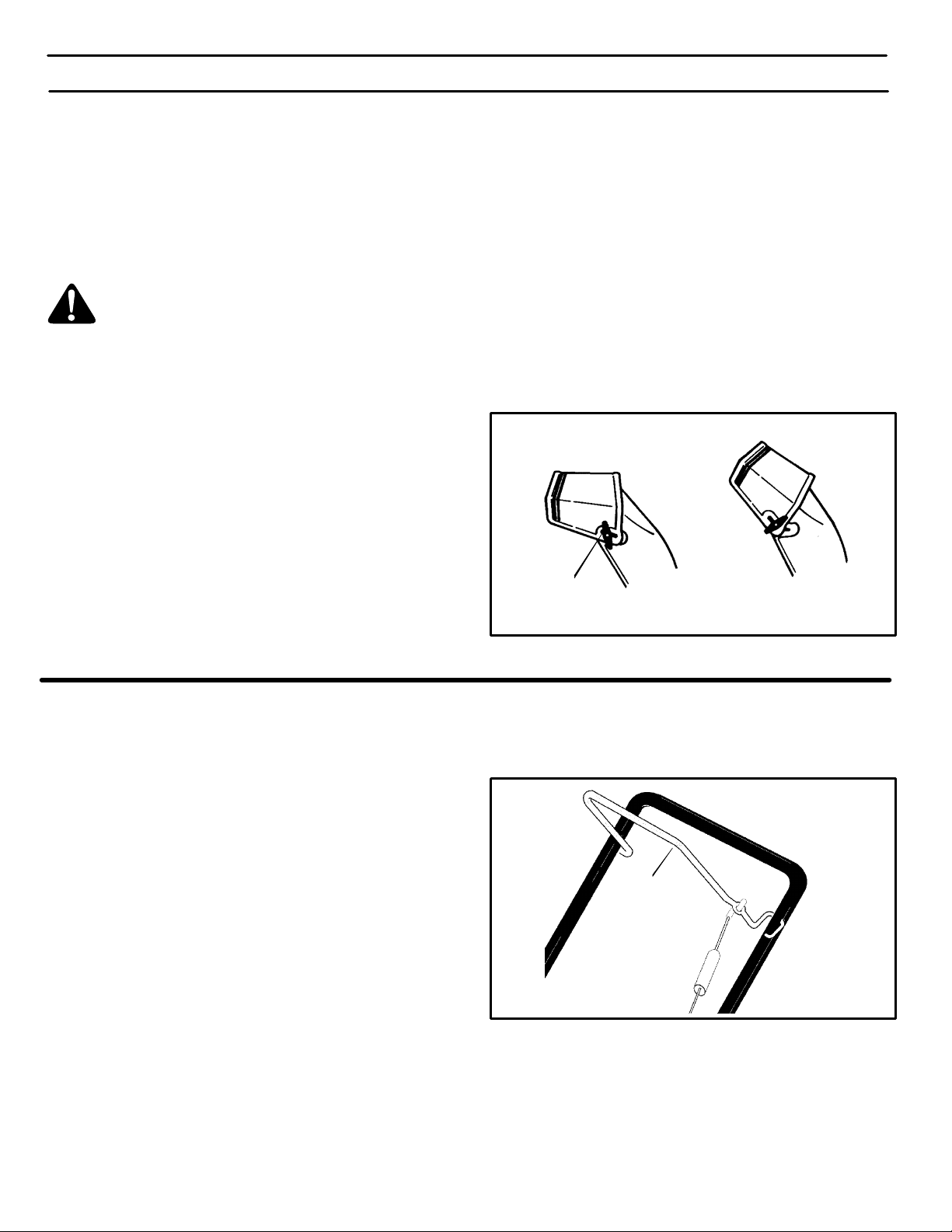
HOW TO CONTROL SNOW DISCHARGE
1. Turn the chute control rod to set the direction of the snow
throwing. (See Figure 7)
2. Loosen the wing knob on the chute deflector and move
the deflector to set the distance. Move the deflector (Up)
for more distance, (Down) for less distance. Then tighten
the wing knob (See Figure 8).
Deflector Down
Deflector Up
HOW TO STOP THE SNOWTHROWER
1. To stop throwing snow, release the auger drive lever.
(See Figure 9).
HOW TO THROW SNOW
1. Engage the auger drive lever. (See Figure 9).
2. To stop throwing snow, release the auger drive lever.
HOW TO MOVE FORWARD
1. Hold the auger drive lever against the handle (See
Figure 9). The auger will begin rotating.
2. To go forward, raise or push forward on the handle to allow
the rubber auger blades to contact the ground. Maintain
a firm hold on the handle as the snowthrower starts to
move forward. Guide the snowthrower by moving the han-
dle either left or right. Do not attempt to push the snowthrower.
3. To stop, release the auger drive lever.
Wing Knob
Figure 8
NOTE: If the auger continues to rotate, see “How To
Adjust The Auger Control Cable” in the Maintenance
section.
Auger
Drive Lever
Figure 9
1740274
14
Page 15

OPERATION
BEFORE STARTING THE ENGINE
WARNING: Experiences indicates that alcohol
blended fuels (called gasohol or those using
ethanol or methanol) can attract moisture
which leads to separation and formation of acids during storage. Acidic gas can damage the fuel system
of an engine while in storage.
NOTE: To avoid engine problems, the fuel system must
be emptied before storage for 30 days or longer. Start
the engine and let it run until the fuel lines and carburetor are empty. Use the carburetor bowl drain to empty
residual gasoline from the float chamber. Use fresh fuel
next season. See the Storage section in this manual for
additional information.
Never use engine or carburetor cleaner products in the
fuel tank or permanent damage can occur.
HOW TO MIX THE FUEL MIXTURE
The two cycle engine, used on this snow thrower, requires a
mixture of gasoline and oil for lubrication of the bearings and
other moving parts. The correct fuel mixture ratio is 50:1
(2.6 oz. oil per one gallon of gas − see the Fuel Mixture
Chart). Gasoline and oil must be pre−mixed in a clean gasoline container. Always use fresh, clean, unleaded gasoline.
FUEL MIXTURE CHART (mixture 50:1)
U.S. IMPERIAL SI. (Metric)
GAS OIL GAS OIL GAS OIL
1 Gal. 2.6
oz.
1 Gal. 3.1 oz. 4
liter
80
ML
Mix gasoline and oil as follows:
1. Pour one (1) U.S. quart of fresh, clean, unleaded automotive gasoline into a one gallon size gasoline container.
2. Add 2.6 ounces of clean, high quality, Husqvarna two−
cycle oil to the gasoline container.
IMPORTANT: Do not use outboard motor oil or multi−viscosity oils,such as 10W−30 or 10W−40.
3. Install the fuel cap onto the gasoline container. Vigorously shake the gasoline container to mix the oil with
the gasoline.
4. Add an additional three (3) U.S. quarts of gasoline to
the gallon container. Again shake the gasoline container.
WARNING: Gasoline is flammable. Always use
caution when handling or storing gasoline.
Do not fill fuel tank while snow thrower is running, when it is hot, or when snow thrower is in an
enclosed area.
Keep away from open flame or an electrical spark and
do not smoke while filling the fuel tank.
Never fill the tank completely. Fill the tank to within
1/4”−1/2” from the top to provide space for expansion
of fuel.
Always fill fuel tank outdoors and use a funnel or
spout to prevent spilling.
Make sure to wipe up any spilled fuel before stating
the engine.
Store gasoline in a clean, approved container and
keep the cap in place on the container.
1740274
Do not fill the fuel tank with gasoline that does not have oil mixed in it. Shake the gasoline container before
each filling of the fuel tank.
OIl
(2.6 oz.)
Gasoline
1U.S.
Quart
1 U.S. Gallon container
Shake Can
Add more gas
(3 U. S. Quarts)
15
1 U.S.
Gallon
Special
Gasoline
Figure 10
Page 16

OPERATION
BEFORE STARTING THE ENGINE
1. Before you service or start the engine, familiarize yourself
with the snow thrower. Be sure you understand the function and location of all controls.
2. Be sure that all fasteners are tight.
HOW TO START THE ENGINE
The following starting instructions include directions for both
Recoil Start and Electric Start engines. For models that are
Recoil Start only, disregard the Electric Start information.
Electric Start models are equipped with a 120 volt AC electric
starter and also a recoil starter. Before starting the engine,
make certain that you have read the following information.
The starter is designed to operate on 120 volt A.C.
household current. Carefully follow all instruc-
tions in the “How To Start The Engine” section.
To connect a 120 volt A.C. power cord, always connect
the power cord to the switch box on the engine first.
Then, plug the other end into the receptacle. When disconnecting the power cord, always unplug the end from
the receptacle first.
3. Before starting the engine, make sure all controls operate
correctly.
HOW TO STOP THE ENGINE
To stop the engine, move the ignition key to the stop position.
8. (Electric Start) Push on the electric start button until the
engine starts. Do not crank for more than 10 seconds at
a time. The electric starter is thermally protected. If the
electric starter overheates, it will automatically stop and
can only be restarted when it has cooled to a safe temperature. A wait of about 5 to 10 minutes is required to allow
the electric starter to cool and the thermal protection to reset..
9. (Recoil Start) Rapidly pull the recoil starter handle. Do
not allow the recoil starter handle to snap back. Slowly
return the recoil starter handle.
10. If the engine does not start in 5 or 6 tries, See the “Trouble
Shooting Chart” Instructions.
11. (Electric Start) When the engine starts, release the elec-
tric start button.
HOW TO START A COLD ENGINE
1. Fill the fuel tank with a fresh, clean fuel mixture. See “How
To Mix The Fuel Mixture”.
2. Move the choke control to FULL position.
3. Make sure the auger drive lever is in the disengaged (released) position.
4. Insert the ignition key and turn to the ON position.
5. (Electric Start) Connect the power cord to the switch box
located on the engine.
6. (Electric Start) Plug the other end of the power cord into
a 120 VOLT, A.C. receptacle. (See the WARNING in this
section).
7. Push the primer button while covering the vent hole as
follows: Remove finger from primer button between
primes.
S Do not prime if temperature is above 50° F (10° C).
S Push twice if temperature is 50° F (10° C) to
15°F (−10° C).
S Push four times if temperature is below 15° F (−10° C).
S Push five time if temperature is below 0° F (−18° C).
1740274
12. (Electric Start) First disconnect the power cord from the
receptacle. Then, disconnect the power cord from the
switch box.
13. As the engine warms up, move the choke control to 1/2
choke position. When the engine runs smoothly, move the
choke control to the off position.
NOTE: Allow the engine to warm up for several minutes
before blowing snow in temperatures below 05F.
WARM START
If restarting a warm engine after a short shutdown, leave choke
at “OFF” and do not push the primer button. If the engine fails
to start, follow the Cold Start instructions.
WARNING: Never run engine indoors or in enclosed, poorly ventilated areas. Engine exhaust
contains CARBON MONOXIDE, AN ODORLESS
AND DEADLY GAS. Keep hands, feet, hair and loose
clothing away from any moving parts on engine and
snow thrower.
The temperature of muffler and nearby areas may exceed 1505F. Avoid these areas.
DO NOT allow children or young teenagers to operate
or be near snow thrower while it is operating.
16
Page 17

OPERATION
HOW TO CLEAR A CLOGGED DISCHARGE CHUTE
WARNING: Hand contact with the rotating impeller inside the discharge chute is the most
common cause of injury associated with snow
blowers. NEVER USE YOUR HAND TO CLEAN OUT
THE DISCHARGE CHUTE.
To Clear The Chute:
S SHUT OFF THE ENGINE!
S Wait 10 seconds to be sure that the impeller blades
have stopped rotating.
S Always use a clean-out tool, not your hands.
SNOW THROWING TIPS
1. When the handle is raised, the auger blades will engage
the ground and the snow thrower will move forward. When
the auger drive lever is released, the auger blades will
stop. If the blades do not stop, see “How To Adjust The Auger Control Cable” in the Service And Adjustment section.
2. Most efficient snow throwing is accomplished when the
snow is removed immediately after if falls.
3. For complete snow removal, slightly overlap each previous path.
4. Whenever possible, discharge the snow down wind.
5. The distance the snow will be discharged can be adjusted
by moving the discharge chute deflector. Raise the deflector for more distance or lower the deflector for less distance.
6. In windy conditions, lower the chute deflector to direct the
discharged snow close to the ground where it is less likely
to blow into unwanted areas.
7. For safety and to prevent damage to the snow thrower,
keep the area to be cleared free of stones, toys and other
foreign objects.
8. Do not use the auger propelling feature when clearing
gravel or crushed rock driveways. Move the handle down
to slightly raise the auger.
9. The forward speed of the snow thrower is dependent on
the depth and weight of the snow. Experience will establish the most effective method of using the snow thrower
under different conditions.
Use a clean-out tool to remove snow from the auger housing.
How To Use The Clean-Out Tool
S Release the auger drive lever.
S Remove the ignition key, if equipped. Pull out the safety
key, if equipped.
S Disconnect spark plug wire.
S Do not place your hands in the auger or discharge chute.
Use a clean-out tool to remove snow or debris.
WARNING: Blockage must be cleared only after
shutting off the snow blower and only with a
clean-out tool, not by hand.
10. After each snow throwing job, allow the engine to run for
a few minutes. The snow and accumulated ice will melt off
the engine.
11. Clean the snow thrower after each use.
12. Remove ice, snow and debris from the entire snow thrower. Flush with water to remove all salt or other chemicals.
Wipe snow thrower dry.
DRY AND AVERAGE SNOW
1. Snow up to eight inches deep can be removed rapidly and
easily by walking at a moderate rate. For snow or drifts of
a greater depth,slow your pace to allow the discharge
chute to dispose of the snow as rapidly as the auger receives the snow.
2. Plan to have the snow discharged in the direction the wind
is blowing.
WET PACKED SNOW
Move slowly into wet, packed snow. If the wet, packed snow
causes the auger to slow down or the discharge chute begins
to clog, back off and begin a series of short back and forth jabs
into the snow. These short back and forth jabs, four to six inches, will “belch” the snow from the chute.
SNOW BANKS AND DRIFTS
In snow of greater depth than the unit, use the same “jabbing”
technique described above. Turn the discharge chute away
from the snow bank. More time will be required to remove snow
of this type than level snow.
1740274
17
Page 18

SERVICE RECOMMENDATIONS
N
SERVICE RECOMMENDATIONS
PROCEDURE
S
Tighten all screws and nuts
O
Lubricate Chute Control
Flange
W
FIRST
2
HOUR
√ √
√ √
BEFORE
EACH
USE
OFTEN
EVERY
5
HOURS
EVERY
10
HOURS
EVERY
25
HOURS
BEGINNING
EACH
SEASON
√
BEFORE
STORAGE
T
Lubricate Auger Bail
H
R
Check Auger Drive Cable
O
Adjustment
(See Cable Adjustment)
W
√ √
√
E
R
Check Drive Belt
The warranty on this snowthrower does not cover items that have been subjected to operator abuse or negligence. To receive
full value from the warranty, operator must maintain snowthrower as instructed in this manual. The following Service Recom-
mendations are supplied to assist operator to properly maintain snow thrower. This is a check list only. Adjustment referred
to will be found in Adjustments/Repairs section of this manual.
√
AFTER EACH USE
1. Check for any loose or damaged parts.
2. Tighten any loose fasteners.
3. After each use, remove all snow and slush off of the
snowthrower to prevent freezing of auger or controls.
4. Check controls to make sure they are functioning
properly.
5. If any parts are worn or damaged, replace immediately.
LUBRICATION
Before Storage
1. Lubricate the chute control flange. Apply a clinging
type of grease such as Lubriplate (see Figure 11).
2. Apply oil to the pivot point on each side of the auger
bail (see Figure 11).
3. Wipe off the excess oil.
Chute Control
Flange
Auger Bail
Pivot
Point
Figure 11
1740274
18
Page 19

SERVICE RECOMMENDATIONS
HOW TO LUBRICATE THE IDLER ARM
CAUTION: DO NOT get oil on the belt or pulleys. This will
cause the belt to slip and experience premature failure.
1. Remove the screws from the belt cover (see Figure 12).
Remove the belt cover.
2. Apply a drop of oil to the idler arm at point B (see
Figure 13).
3. Pivot the auger bail up and down several times.
4. Wipe off the excess oil.
5. Install the cover.
Idler Arm
B
Figure 13
1740274
Belt Cover
Figure 12
19
Page 20

MAINTENANCE
HOW TO ADJUST THE BELT TENSION
IMPORTANT: When you release the auger bail, the auger must stop rotating. If the auger does not stop, adjust the belt tension as follows:
1. Disconnect the spark plug wire from the spark plug.
2. Remove the belt cover.
3. Loosen the idler pulley nut (see Figure 15).
4. Move the idler pulley to the bottom of the idler arm
slot. If the idler pulley is already in the bottom position, replace the auger belt. See How To Replace The
Auger Belt in the Maintenance section.
5. Tighten the idler pulley nut.
6. Install the belt cover.
HOW TO REPLACE THE AUGER BELT
1. Disconnect the spark plug wire from the spark plug.
2. Remove the belt cover (see Figure 12).
3. Remove the belt guide (see Figure 15).
4. Remove the auger belt from the engine drive pulley.
5. Push down the idler arm to move the brake away the
auger drive pulley. Remove the auger belt from the
auger drive pulley.
6. Loosen the idler pulley nut. Move the idler pulley to the
top of the idler arm slot. Tighten the idler pulley nut.
7. Install a new auger belt.
8. Install the belt guide. Make sure the fasteners that
secure the belt guide are tight.
9. Check the operation. When you release the auger
bail, the auger must stop turning. When you engage
the auger bail, there MUST be clearance between the
brake arm and the auger drive pulley.
10. When you release the auger bail, the auger must stop
rotating. Make sure the brake contacts the auger
drive pulley (Figure 15) and that the auger cable
spring (Figure 14) has slack (no tension). If not, check
the cable spring adjustment as follows:
11. Remove the boot from the auger cable spring as follows:
S Disconnect the end of the idler spring from the
idler arm (see Figure 15).
S Remove the auger belt from the idler pulley.
S Remove the end of the auger cable spring from
the auger bail (see Figure 14).
S Remove the boot from the auger cable spring.
S Attach the end of the auger cable spring to the
auger bail.
12. To adjust the auger cable spring:
S Install the auger belt to the idler pulley (see
Figure 15).
S Attach the idler spring to the idler arm.
S Loosen the jam nut (see Figure 14).
S Turn the adjuster until the auger cable is slightly
slack.
S Tighten the jam nut.
13. Remove the idler spring from the idler arm (see
Figure 15). Remove the auger belt from the idler
pulley. Install the boot onto the auger cable spring.
14. Install the auger belt, idler spring, and belt cover.
Auger Cable Spring
Boot
Jam Nut
Adjuster
Auger Cable
Auger
Bail
Figure 14
1740274
Auger
Drive
Pulley
Brake
Idler Arm
Auger
Belt
Idler
Spring
20
Idler Pulley
Belt Guide
Idler Pulley
Nut
Engine Drive
Pulley
Figure 15
Page 21

MAINTENANCE
HOW TO REPLACE THE SCRAPER BLADE
1. Use adjustable wrenches to remove the fasteners that
secure the scraper blade (Figure 16).
2. Install a new scraper blade and secure with the
fasteners removed in step 1.
HOW TO FREE THE AUGER CABLE
IMPORTANT: If the auger cable will not move when you
ENGAGE the bail, the auger cable could be frozen inside the conduit. DO NOT pull on the auger cable.
Instead, thaw the conduit and lubricate the auger
cable.
1. Thaw the conduit so the auger cable moves freely.
2. Work grease into the opening on the top of the conduit
where the auger cable enters.
Scraper Blade
Figure 16
1740274
Conduit
Figure 17
21
Page 22

MAINTENANCE
WARNING: To prevent accidental starting when
making any adjustments or repairs, always disconnect the spark plug wire and place it where
it cannot make contact with the spark plug .
HOW TO ADJUST THE CHUTE CRANK
If the chute crank will not rotate fully to the left or right, adjust
as follows.
1. Remove the top cover. See “How To Remove The Top
Cover”.
2. Using an adjustable wrench, loosen the nuts.
3. Move the crank adjusting bracket to allow 1/8 inch
(3mm) clearance between the notch in the flange and
the outer diameter of the worm gear.
4. Tighten the nuts.
Nut
Flange
1/8” (3mm)
Crank Adjusting
Bracket
Worm Gear
Figure 18
HOW TO ADJUST THE AUGER CONTROL CABLE
The auger control cable is adjusted at the factory. During normal use, the auger control cable can become stretched and
the auger drive lever will not properly engage or disengage
the auger.
1. Remove the end of the auger cable spring from the au-
ger bail (see Figure 19).
2. Remove the boot from the auger cable spring.
3. Attach the end of the auger cable spring to the auger
bail.
4. Loosen the jam nut (see Figure 19).
5. Turn the adjuster until the auger cable is slightly slack.
6. Tighten the jam nut.
7. Remove the end of the auger cable spring from the au-
ger bail and install the boot.
8. Attach the end of the auger cable spring to the auger
bail.
Auger Cable Spring
Boot
Jam Nut
Adjuster
Auger Cable
Auger
Bail
Figure 19
9. To check the adjustment, start the snow thrower. Make
sure the auger does not rotate when the auger drive lever
is released.
1740274
22
Page 23

HOW TO REPLACE THE DRIVE BELT
MAINTENANCE
The drive belt is of special construction and must be replaced with original factory replacement belt available from
your nearest authorized service center.
1. Remove the belt cover. (See Figure 20)
2. Remove the drive belt from the idler pulley. (See
Figure 20 and Figure 21)
3. Remove the drive belt from the engine pulley. Be
careful, not to bend the belt guides.
4. Remove the drive belt from the auger pulley. (See
Figure 20)
5. Remove the old drive belt.
6. To install the new drive belt, reverse the above steps.
7. Make sure the drive belt is seated properly on the pulleys.
NOTE: When the auger control lever is engaged, the
belt guides must be 1/16” from the drive belt (See
Figure 21).
Engine
Pulley
Idler Pulley
Drive Belt
Auger Pulley
Belt Cover
Figure 20
8. Install belt cover.
Auger Pulley
Drive Belt
Idler Pulley
Engine Pulley
Belt Guide
1/16”
Belt Guide
1740274
Figure 21
23
Page 24

HOW TO REPLACE THE AUGER
MAINTENANCE
1. Remove the belt cover. See “How To Remove The Belt
Cover”.
2. Remove the drive belt. See “How To Replace The Drive
Belt”.
3. Use a 1-inch wrench and remove the auger pulley
from the auger shaft (threads are left hand; turn clockwise to remove). (See Figure 22).
4. To keep the auger from rotating, set a 2”x4” piece of
wood on the center paddle to secure auger.
5. Use a 7/16-inch wrench and remove the fasteners from
the bearing assembly. Remove the bearing assem-
bly from the auger housing.
6. Slide the auger out of the bearing assembly on the
right side of the snow thrower.
7. Tip the auger enough to allow the auger to slide out of
the auger housing.
8. To install auger, reverse the above steps.
Wood
Auger Housing
1740274
Center Paddle
Auger
Bearing Assemlby
Auger Pulley
Figure 22
24
Page 25

MAINTENANCE
TO ADJUST THE CARBURETOR
The carburetor is not adjustable. Engine performance
should not be affected at altitudes up to 7,000 feet. For
operation at higher elevations, contact your nearest authorized service center.
IMPORTANT: Never tamper with the engine governor,
which is factory set for proper engine speed. Over−speed-
ing the engine above the factory high speed setting can be
dangerous. If the engine−governed high speed needs an
adjustment, contact an authorized service center. They
have the proper equipment and experience to make any
necessary adjustments.
TO ADJUST OR REPLACE THE SPARK PLUG
Fuel Cap
Shroud
THIS SPARK IGNITION SYSTEM COMPLIES WITH
CANADIAN ICES-002.
Check the spark plug every twenty−five (25) hours. Replace the spark plug if the electrodes are pitted or burned
or if the porcelain is cracked.
The spark plug is housed in the engine compartment under
the top cover and cannot be seen under normal conditions.
WARNING: STOP the engine. Wait for it to cool
before removal of spark plug.
CAUTION: DO NOT clean the plug with abrasives.
1. Remove the fuel cap (see Figure 23).
2. Remove the screws from the shroud. Remove the
shroud. Install the fuel cap.
3. Disconnect the spark plug wire (see Figure 24).
4. Clean the area around the spark plug base to prevent dirt
from entering the engine when the spark plug is re-
moved.
Spark Plug
Wire
Figure 23
Spark
Plug
Figure 24
5. Remove the spark plug.
6. Check the spark plug. If the spark plug is cracked,
fouled or dirty, it must be replaced .
7. Set the gap between the electrodes of the new spark
plug at 0.030 inch (Figure 25).
8. Install the spark plug in the cylinder head and firmly tight-
en. Recommended torque is 18 to 20 foot pounds. Attach
the spark plug wire.
9. Remove the fuel cap and install the shroud (see
Figure 23).
10. Install the fuel cap.
1740274
.030” (0.76 mm) Gap
Figure 25
25
Page 26

STORAGE
OFF SEASON STORAGE
WARNING: Never store the engine, with fuel in
the tank, indoors or in a poor ventilated enclo-
sure where fuel fumes could reach an open
flame, spark or pilot light as on a furnace, water heater,
clothes dryer, etc.
Handle gasoline carefully. It is highly flammable and
careless use could result In serious fire damage to your
person and /or property.
Drain fuel into approved containers outdoors, away
from open flame.
If the snowthrower is to be stored for thirty (30) days or more
at the end of the snow season, the following steps are
recommended to prepare your snowthrower for storage.
NOTE: Gasoline must be removed or treated to prevent
gum deposits from forming in the tank, filter, hose, and
carburetor during storage.
1. To remove gasoline, run engine until tank is empty and
engine stops.
If you do not want to remove the gasoline, add fuel stabilizer
to any gasoline left in the tank to minimize gum deposits and
acids. If the tank is almost empty, mix stabilizer with fresh
gasoline in a separate container and add some to the tank.
ALWAYS FOLLOW INSTRUCTIONS ON STABILIZER
CONTAINER. THEN RUN ENGINE AT LEAST 10 MINUTES
AFTER STABILIZER IS ADDED TO ALLOW MIXTURE TO
REACH CARBURETOR. STORE SNOWTHROWER IN
SAFE PLACE.
2. Lubricating the piston/cylinder area. This can be done by
first removing the spark plug and squirting clean engine
oil into the spark plug hole. Then cover the spark plug
hole with a rag to absorb oil spray. Next, rotate the engine
by pulling the starter two or three times. Finally, reinstall
spark plug and attach spark plug wire.
3. Thoroughly clean the snowthrower.
4. Lubricate all lubrication points (see “Lubrication“ in the
Service Recommendations section).
5. Insure that all nuts, bolts, and screws are securely fastened. Inspect all visible moving parts for damage,
breakage, and wear. Replace if necessary.
6. Touch up all rusted or chipped paint surfaces; sand lightly
before painting.
7. Cover the bare metal parts of the blower housing and auger with rust preventative.
8. If possible, store your snowthrower indoors and cover it
to give protection from dust and dirt.
9. On models with folding handles, loosen the knobs that
secure the upper handle. Rotate the upper handle back.
10. If the machine must be stored outdoors, block up the snowthrower and insure the entire machine is off the
ground. Cover the snowthrower with a heavy tarpaulin.
REMOVING THE SNOWTHROWER FROM
STORAGE
When removing the snowthrower from storage, follow the
steps below.
1. Put the upper handle in the operating position, tighten the
knobs that secure the upper handle.
2. Fill the fuel tank with a fresh fuel−oil mixture. See “How
to Mix The Fuel Mixture” in the Operation section.
3. Lubricate the auger bail and idler arm.
4. Check the spark plug. Make sure the gap is correct. If the
spark plug is worn or damaged, replace before using.
5. Make sure all fasteners are tight.
6. Make sure all guards, shields, and covers are in place.
7. Make sure all adjustments are correct.
1740274
26
Page 27

TROUBLE SHOOTING CHART
PROBLEM LOOK FOR REMEDY
Difficult starting Defective spark plug. Replace defective spark plug.
Engine runs erratically Blocked fuel line. Clean fuel line.
Empty gas tank. Check fuel supply,
Stale gasoline. Add fresh gasoline.
Water or dirt in fuel system. Remove carburetor bowl to drain fuel tank. Refill
with fresh fuel. CAUTION: Do not remove
carburetor bowl when the engine is hot.
Engine stalls Unit running on CHOKE. Set choke lever to RUN position.
Loss of power Gas cap vent hole is plugged. Remove ice and snow from cap. Be sure vent
hole is clear.
Excessive vibration Loose parts. Stop engine immediately and remove spark plug
wire. Tighten all bolts and make all necessary
repairs. If vibration continues, have the unit
serviced by a competent repairman.
Unit fails to propel
itself
Unit fails to discharge
snow
Drive belt loose or damaged. Replace drive belt. Refer to Drive Belt
Replacement in the Maintenance section of this
manual.
Incorrect adjustment of traction drive
cable.
Auger drive belt loose or damaged. Replace or adjust auger drive belt. Refer to Drive
Auger control cable not adjusted
correctly.
Discharge chute clogged. Stop engine immediately and disconnect spark
Foreign object lodged in auger. Stop engine immediately and disconnect spark
Adjust traction drive cable. Refer to Cable
Adjustment in the Maintenance section of this
manual.
Belt Replacement and Drive Belt Adjustment in
the Maintenance section of this manual.
Adjust auger control cable. Refer to Cable
Adjustment in the Maintenance section of this
manual.
plug wire. Refer to the first Warning in
Snowthrower Operation in the Operation
section of this manual. Clean discharge chute
and inside of auger housing.
plug wire. Remove object from auger housing.
Identifying Your Snowthrower
Your new snowthrower has two (2) identifying numbers: (1) unit model number: (2) unit serial number. The two preceding
numbers are required to insure that the proper replacement parts are obtained when required. If you have any questions
concerning parts, service, or technical data, contact your nearest Authorized dealer.
For complete warranty information refer to the warranty in the Owner’s Information section of this manual.
1740274
27
Page 28

 Loading...