

Husqvarna 326P5X, 326P4X Owner’s Manual

Operator's manual (CARB II) /r _
326P4 326P4x.SER, ES
326P5x.SER, ES
Please read these instructions carefully and make
sure you understand them before using the machine. English

Symbols
SYMBOL EXPLANATION
WARNING! Tiffs nlachine can be
dangerous. Cra'eless or incorrect use
can _x_sultin serious or Fatal inlury lo
the operator or others,
Read through the Operaior's Mramal
can_thlly and under.lined the con*ent
before uMng the machine.
Always use
• A protective hehnet where there Ls
a rLsk of falling ol_jecis
• Era' protection
• Approved eye proteciion
• Alwws wear approved protective
gloves,
• Use anti-slip ra_d siable boots,
Other symbols!decals on the machine refer to
special certification requirements for certain
markets.
• Checks ra_dior rnainlenance should
be carried out with the engine
swiiched off, with the stop swilch
in the STOP position.
• ]'hks product ksin accordance wtth
applicable CE direciives.
• This machine Lsnot electrically
insulated, If the machine louches
or conies close to high-voltage
powra' lines it could lead to death
or serious irlluW, Eleciricity can
.jump Dom one point to another by
arcing. The higher the voltage, the
g*xmterthe distance electdctty can
.jump Electricity cra_also travel
itu'ough branches and other
oblects, especially if th W are wet.
Alwayskeepa safedLstm_eeoFat
least I0 ni ('30 It) between the
machine and high-voltage power
lines and/or aW ot_ieelsthat are
iouct_ng them. If you need to
wo*Ckcloser than this alwws
coniact the *xd_'m_tpower
company to make sure the power is
switched oFFbefore you stra_ wo*¢k.
• Alwws wear approved protective
gloves,
• Regulra' cleaning required.
• Oculra' comroL
• Approved we protec{ion mus{
always be u_sed.
- Ee<41sh
• Tiffs n_tchine has a long reach.
Make sure that no people or
animals come closer limn 15 m (45
FI)when the machine is running.
• Chain oil ra_dchain off flow
adJtLstnlem
CONTENTS
Husqvarna AB has a policy of continuous product dev*dopment
zmd therefotx_ reserves the right to modify the design and
appe_'ance of products wit}tout prior notice,
List of contents
Maintenance, replacement, or repair of the emission control
de_ices and systems may be performed by any nonroad
engine repair establishment or individual
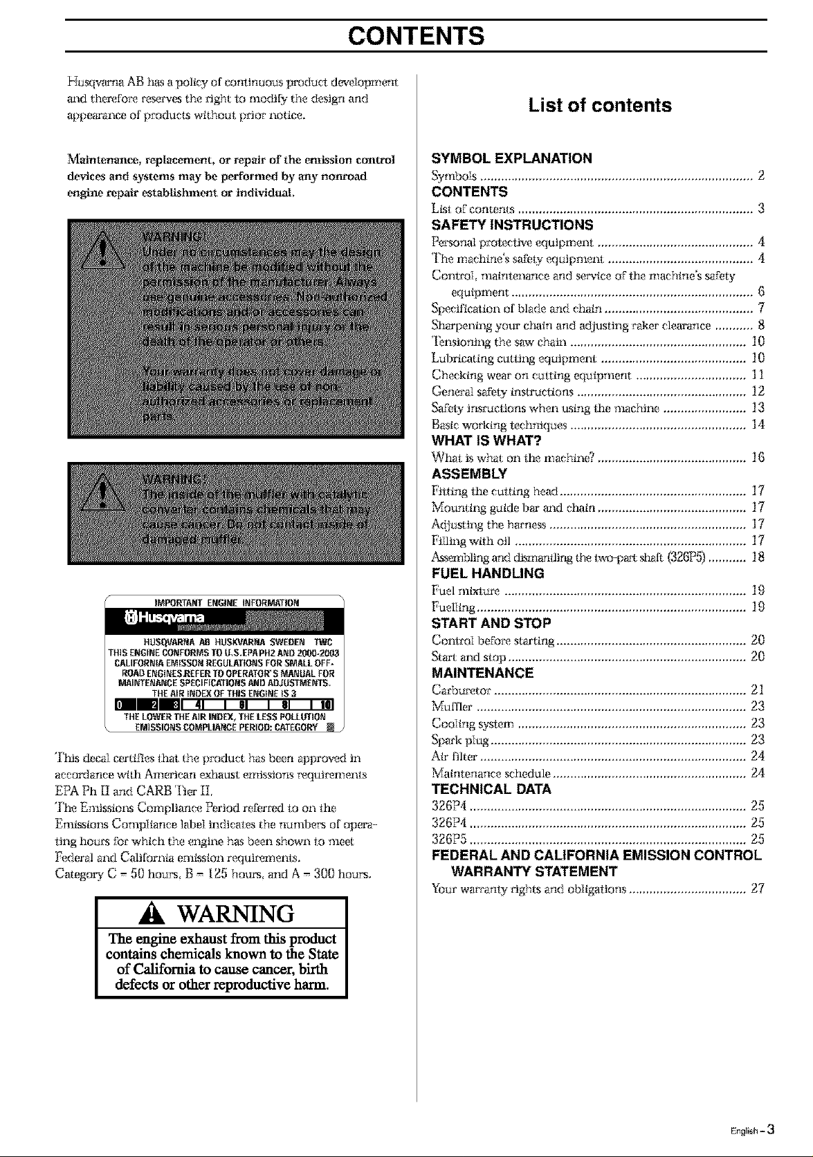
IMPORTA_f ENGINE INFORMATI01_
']'iris decal certifies that the product has been approved in
accordance wtth American exhaust emissions tx_qui*x_ments
EPA Ph [I and CARB Tier II,
The Emissiom Compliance Period referred to on the
Emkssioos Compiiance label indicates the nvnibet's of opera-
ling hou*'sfor which the engine has been shown to meet
Federal and California emkssion requiremems.
Category C = 50 hours, B = 125 hour, and A = 300 hours,
SYMBOL EXPLANATION
Symbols ............................................................................... 2
CONTENTS
L_st of contents ................................................................... 3
SAFETY INSTRUCTIONS
Personal protec_ve equipment ............................................. fl
The machine's safety equipment .......................................... 4
Comroi maintenance and service of fhe nlachine's safety
equipment ................................................................. (_
Specification of blade and chain ......................................... 7
Sharpening you*' chain and adjusting rakes clearance ........... 8
*I_nsiontng the saw chain ................................................... 10
Lubricating cutting equipment ......................................... 10
Checktng wear on cutting equipment ................................ ] 1
General safety tnsu'uctions ................................................. 12
Safety JnsI_ctioI'IS _ghen tLstng the machine ........................ 13
Bastc worktng techniques ................................................... 14
WHAT IS WHAT?
What is what on the machin_ ........................................... 16
ASSEMBLY
[qtting the cutting head ...................................................... 17
Mounting guide 13_'mad chain ........................................... 17
A({}usting the tmrness ......................................................... 17
Filling wtlh oil ................................................................ 17
_'-g'mMing and dtsmantlirg the t_vo-p_ sl_fl (326P5)........... 18
FUEL HANDLING
Fuel mlxtur_ .................................................................... 19
Fueliing ............................................................................. 19
START AND STOP
ContmI b_fotx_ starting ....................................................... 20
St_'t and stop ..................................................................... 20
MAINTENANCE
Carbu*x_tor......................................................................... 21
_uffler ............................................................................ 23
Cooling system .................................................................. 23
Spark plug .......................................................................... 23
Air filter ............................................................................. 24
Matntenance schedule ........................................................ 24
TECHNICAL DATA
326P4 .............................................................................. 25
326P4 ................................................................................ 25
326P5 ................................................................................ 25
FEDERAL AND CALIFORNIA EMISSION CONTROL
WARRANTY STATEMENT
Your warranty t'tghts and obltgattons .................................. 27
WARNING
The engine exhaust from this product
contains chemicals known to the State
of California to cause cancer, bh'th
defects or other reproductive harm.
English - 3
SAFETY INSTRUCTIONS
Personal protective equipment
IMPORTANT INFORMATION
If used incorrectly or carelessly this machine
can become a dangerous tool that can cause
serious or fatal injury to the operator or others. It
is extremely important that you read and underst-
and the content of this manual.
When using the machine, personal protective
equipment approved by the appropriate
authorities must be used. Personal protective
equipment does not eliminate the risk of
accidents. However, it can reduce the effects of
an injury in the event of an accident. Ask your
dealer for help when choosing protective
equipment.
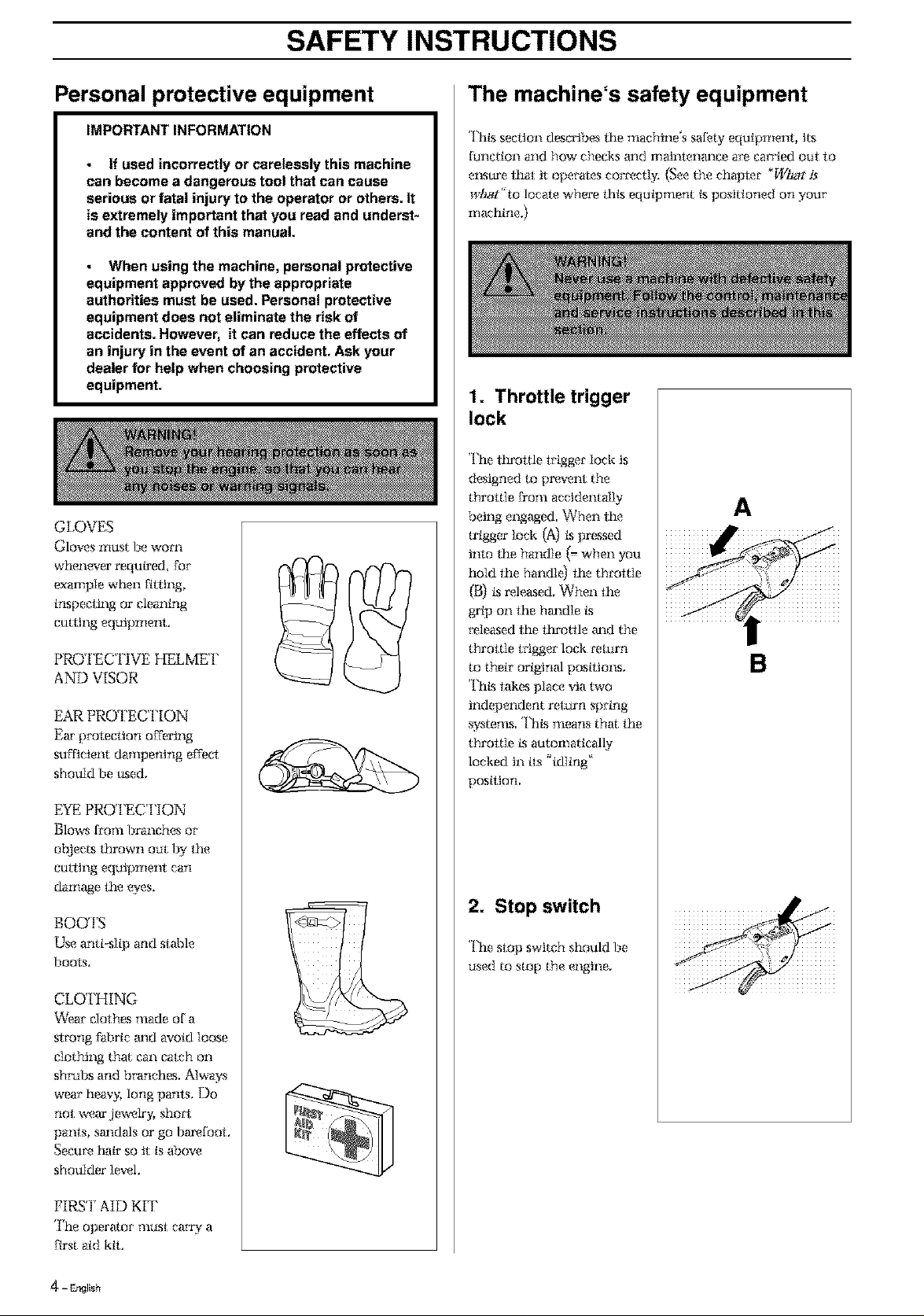
GLOVES
Gloves must lie worn
whenemer required, for
example when fitltng,
inspeciing or cleaning
culling equipment,
PRO FEC FIVE HELME 1'
AND VISOR
EAR PROTEC I'[ON
Ear protecllon offering
sufficient dampening elfeel
should be used,
EYE PRO FEC ]'ION
Blmvs from branches or
oblects thrown out by the
culling equipmeni can
damage the eyes.
BOOTS
Use anti-slip and siable
boots,
The machine's safety equipment
Thks seeiton desca'ibes the machine's safety equipment, Its
function and how checks m_d mainlenm_ee m_ em_'ied o_t to
e1_.surethai; tt operatvs corr_ctI 5 (See the chaplet "WDat is
wDat"to locate where thks equipment ks positioned on your
machine,)
1. Throttle trigger
lock
The throttle lrigger lock ts
designed to pr_,ent the
throttle Dora accidental]>,
being engaged When lhe
trigger loci{ (A) ks pressed
hlto the handle (=when you
hold the handl_t the throltle
(B) ksreleased, When the
grip on the hm_dle ks
*_leesed the ttu'otlle m_d the
throttle trigger lock celurn
to their original postties_s,
<['titstakes place via two
independent relm'n spring
systems Thks means tha the
throttle ks automatically
locked tn its _idling'
position,
2. Stop switch
The stop switch should be
used to stop the engine,
A
B
CLOTHING
Wear clothes made of a
sirong fabric mid avoid loose
clothing that can ealch on
shrubs and branches, Always
wear heavy, long pants. Do
not werw jewelry, sho_9
paros, sandals or go bmx_fooh
Secure hair so tt is above
shoulder level.
FIRS']' AID KIT
The operator musl carry a
first aid kiL
4 - EP,gllsh
SAFETY INSTRUCTIONS
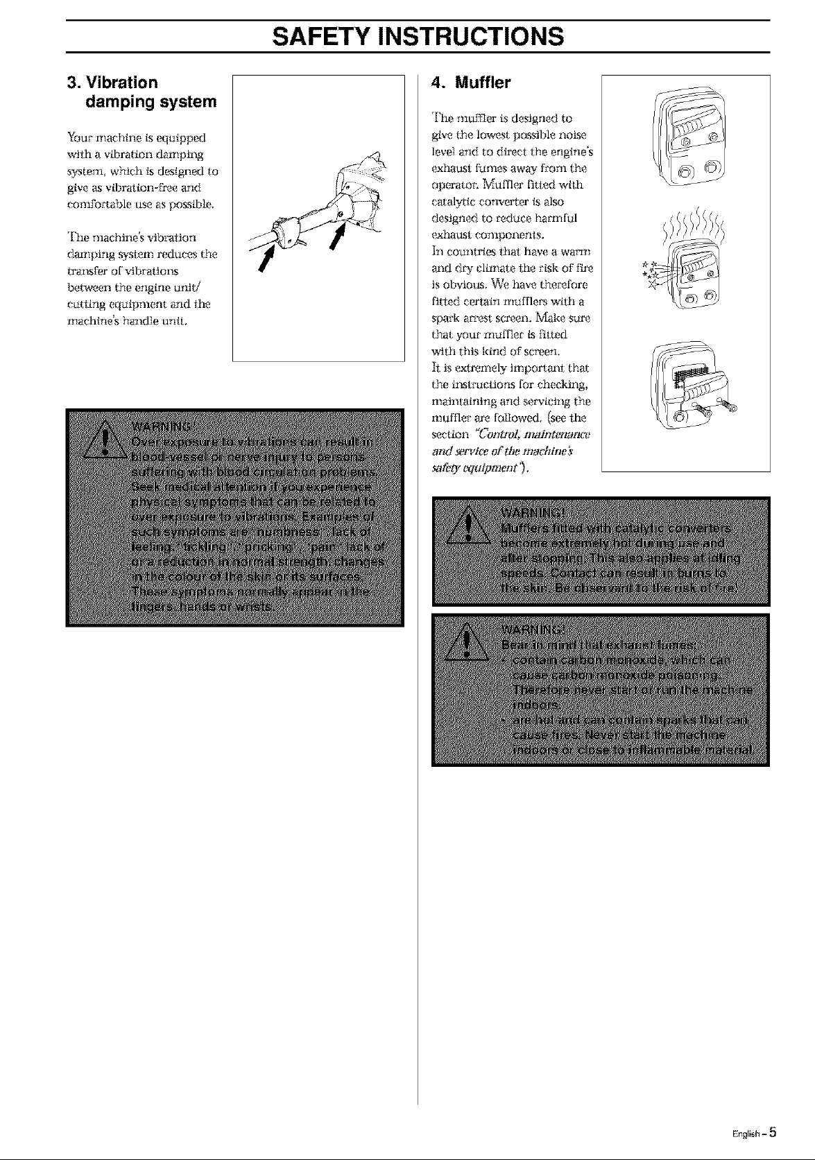
3. Vibration
damping system
Your nlachine ksequipped
wtlh a vibration damping
system, which ksdesigned to
give as vii)ration-free and
comfoaable use as posstble,
The machine's vibraiton
daznping _'slem reduces the
traP.sfer of vtbi'atioP.s
between the engine unit/
catting equipment and the
nlaehine's handle untL
4. Muffler
The mumer is designed to
give the lowest possible noise
level and to direct the engine's
exhat_st fumes away from the
operator: Muffk,' fitted wtth
catalytic converter ksalso
designed to *_duee hamfful
(_haust components.
In countries lhat have a warm
and d W climate lhe risk of fire
is obvious. _'e t_lve the_'efore
fitted certain nmffle*_ with a
spark arrest sca_,_en.Make s_r_
that your hi,If fief ks fitted
with this kind of screen,
h: is (_tremely importm_i tha
the i1_stcoctions for checking,
mainlaining and servicing the
nmffler am followed (see lhe
section _Control, maintenantv
and *t,rvice of the machine}
_1_'0" WuiP merit '},
.1111111111
English = 5
SAFETY INSTRUCTIONS
Inspecting, maintaining and
servicing machine safety equipment
IMPORTANT INFORMATION
All service and repairs to the machine require
special training.
This applies especially to the machine's safety
equipment. If the machine does not meet any
of the controls listed below you should
contact your service workshop.
The purchase of one of our products
guarantees that professional repair and
servicing will be carried out on it. If the point
of purchase is not one of our servicing
dealers, please ask for details of the closest
service workshop.
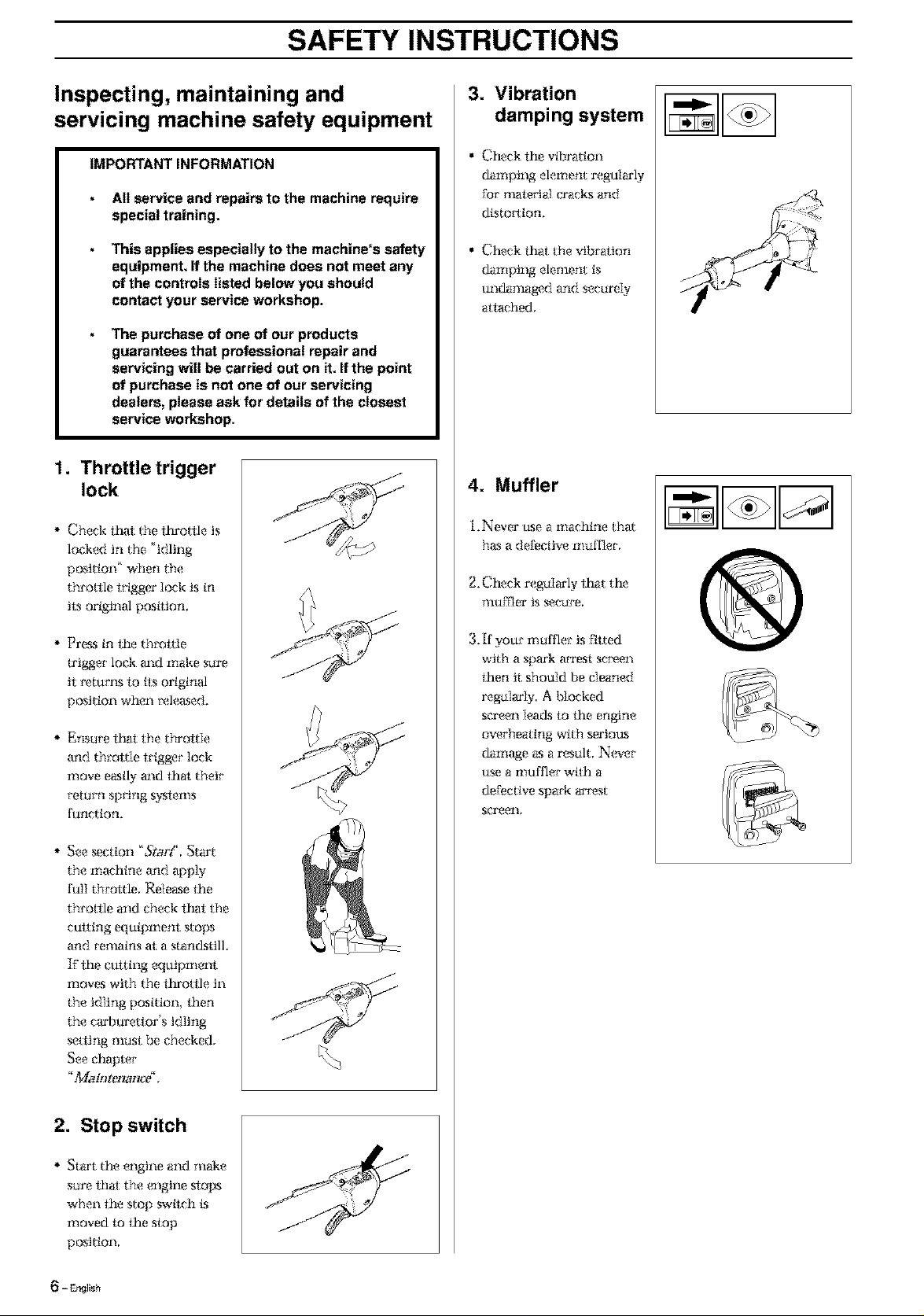
1. Throttle trigger
lock
Check t_l: the ttn'o/tle is
locked in the 'idling
position' when the
throttle trigger lock is in
its original postlion,
3. Vibration
damping system
• Check the vfl)ration
damping element regularly
for illatelJal cx'acks and
distortion,
• Check that the vibration
damptog elenlent is
undamaged and securely
attached,
4. Muffler
i.Never use a nlachine that
has a defective muffler,
2. Check regaIarly lhat the
muffler is secure,
Press in the throttle
u'igger lock m_d make sure
it i_turl_,slo its original
position when _xdeased.
Ensure t_t the throttle
and throl:tle trigger lock
move easily and thai; their
return spring systems
function.
* See section 'StorY, Start
the machine and apply
full throttle, Release the
throAle and check that the
cutting equipment stops
and remains at a stan_kstilL
If lhe cutting equipment
nloves with the fhrottle in
the idling position then
the craq]urettor's idling
setting must be checked,
See chapter
_+%.Ioh)ten_nag,
3. If your muffler is ftlted
with a spark arrest sc_x_en
then it should be cleaned
regularly A Socked
screen lea(ks to the engine
overheating with sertou_s
damage as a result. N(wer
use a muffler wtlh a
defective spark ar_x_st
screell,
J
2. Stop switch
Start the engine and make
sure thai; the engine ,slops
when the stop switch ks
moved to the stop
position,
- EP4_Ish
SAFETY INSTRUCTIONS
5. Cutting equipment
ThLs section describes how f_ough corix_et maintenance and
through using the _Jght t91)e of cutting equipment you can:
• Obtain maximum curling capacity.
• Increase the service life of the cutting equipment.
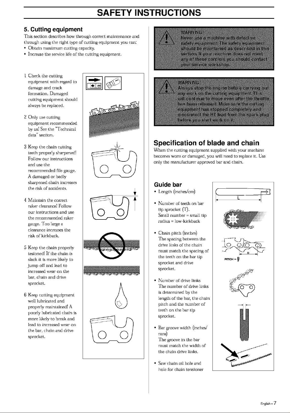
i Check the cutting
equipment with regard lo
damage m_d era(k
formaion. Damaged
cutting equipment should
always be replaced.
2 Only use cutting
equipment recommended
by us_ See the "l'echnical
data" secllon,
3 Keep the chain cutting
teeth properly sha_ened!
Follow our instructiol_s
and use the
recommended file gauge,
A damaged or badly
sharpened chain inc*x_ases
the *'isk of accidenls.
4 Maintain the correct
*'ake*"elearancd Follmv
our instructim_,sand use
the *'eeommended raker
gauge, Too ]arge a
c]earance increases ihe
rLgkof kickback,
5 Keep the chain properly
tesioned! If the chain is
slack it Ls mo_x_ likely to
Jump off m_d lead to
increased wear on i_e
bar chain m_d drive
sprocket.
8 Keep cutting equipment
wd] lubricated and
propeiqy nmintained! A
poor{y iubricated chain is
nlore ]ikely to b*x_akand
lead to increased wear on
the bar chain and drive
sprocket,
© ©
© ©
Specification of blade and chain
Vv'her the cattir g equipnient supplied with your nlaehine
becomes worn or damaged, you will need to replace it. Use
only the manufactar<_r approved bar and chain.
Guide bar
• Length (inchesicni)
• Number of teeth on bar
tip sprocket (*1).
Small number = small tip
radius = low-kickback
• Chain pilch (inches)
The spacing between lhe
drive links of the chain
must nlatch the spacing of
the leeth on the bar tip
sprocket and drive
sprocket,
• Number of drive links
The number of drive ]inks
Lsdetermined by the
]engfh of ihe bar, the chain
pitch and the number of
leeth on the bar tip
sprocket,
• Bar g*'oovewidth (inches/
TlllI1)
The groove in the bar
must match the width of
the chain d*Jve links.
PITCH = D
• Saw chain oil hole and
hole for chain tensioner
English - 7
SAFETY INSTRUCTIONS
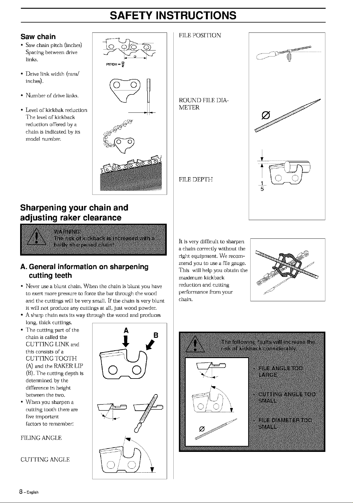
Saw chain
Saw c_in pitch {inches}
Spacing between drive
links,
PITCH = D
Drive link width (ram/
inch_.
Namber of drive links.
Level of kickbak _duciJon
The level of kickback
_'educlion offered by a
chain is indicated by its
r! iodeI nu;llbec
Sharpening your chain and
adjusting raker clearance
FILE POSI I'ION
ROUND FILE DIA-
METER
FILE DEP I'H
5
A. General information on sharpening
cutting teeth
* Nexer use a bIunt chain. When lhe chrdn is blunt you have
to (_e_ rno_ p_?ssure to force the bar lhrough the wood
and the cutiin_s will be vec¢ sinai1, F the chain ks very bIunt
it will not produce any cm:tings a all just wood powden
A shaq) chain eats ils way through the wood a_d produces
long, lhick cutiings.
The curling part of the
chain ks called lhe
CUTTING LINK and
this consists of a
CUT'IING TOOTH
(A) and the RAKER LIP
(B). The curling depfli is
determined by the
difference in height
between the two.
When you sharpen a
culting looth there are
five important
faciors to _a_llellfl)er;
0 0
h is veW difficult to sharpen
a chain corr_ctly without the
_'ight equipment, _e recom-
mend you to use a file gauge,
This will help you obtain lhe
maximum kickback
_duction and culting
perfomlance froTll yOUI"
chain.
FILING ANGLE
CUT I'ING ANGLE
8 - DNIsb
SAFETY INSTRUCTIONS
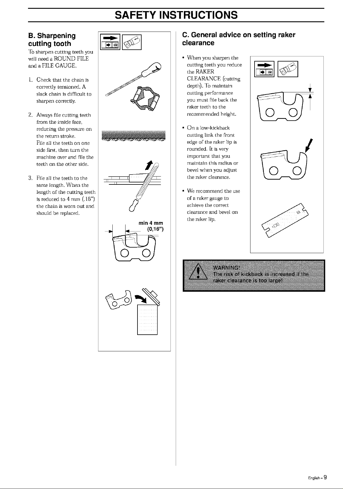
B. Sharpening
cutting tooth
'lb shaq)en catting teeth you
wiIl need a ROUND FILE
and a FILE GAUGE.
i. Check t_l: the chain is
correctly le1_aioned. A
slack ctmin is difficult to
sharpen cora'eclly.
2, Always file ctltting leeth
from the inside Nee
*'educing the pressure on ............................................................................
the i_turn sl:_'oke.
File all the teeth on one
side First then turn the
machine over and file the
teeth on the other side.
3. File all the teeth to the
same length. When the
length of the culting leeth
is reduced m 4 mm (.16")
the chain ksworn out and
should be repIaced.
min 4 mm
C. General advice on setting raker
clearance
When you stmrpen the
curling teeth you reduce
the RAKER
CLEARANCE (crating
depth), *lbmaintain
cutting perFornmnce
you musl file back the
raker leeth to the
recommended height,
On a Iow-ktcM)ack
curling link the Front
edge of the raker iip ks
rounded, It ksveW
important f_t you
mainIatn thLs radius or
bevel when you adjust
the raker clearance,
We recommend the use
of a taker gauge m
act_eve the cors_ct
clearm_ce m_d bevel on
the taker Iip,
0
i
English - 9
 Loading...