

Page 1

English
Workshop manual
322, 322L, 325, 325L, 522L
Page 2

Workshop Manual
Brush cutters, Trimmers,
Pruners, Hedge trimmers
List of Contents
1. Starter ___________________________________ 3
2. Ignition system ____________________________ 7
3. Fuel system _______________________________ 11
4. Centrifugal clutch _________________________ 19
5. Angle gear _______________________________ 23
6. Cylinder and piston _______________________ 27
7. Crankshaft and Crankcase _________________ 31
This supplement only takes up elements specific
to the above mentioned models.
For complete information when servicing we recommend that the supplement is studied together
with the Workshop Manual.
© Copyright Husqvarna AB, Sweden 1998
1
Page 3

2
Page 4
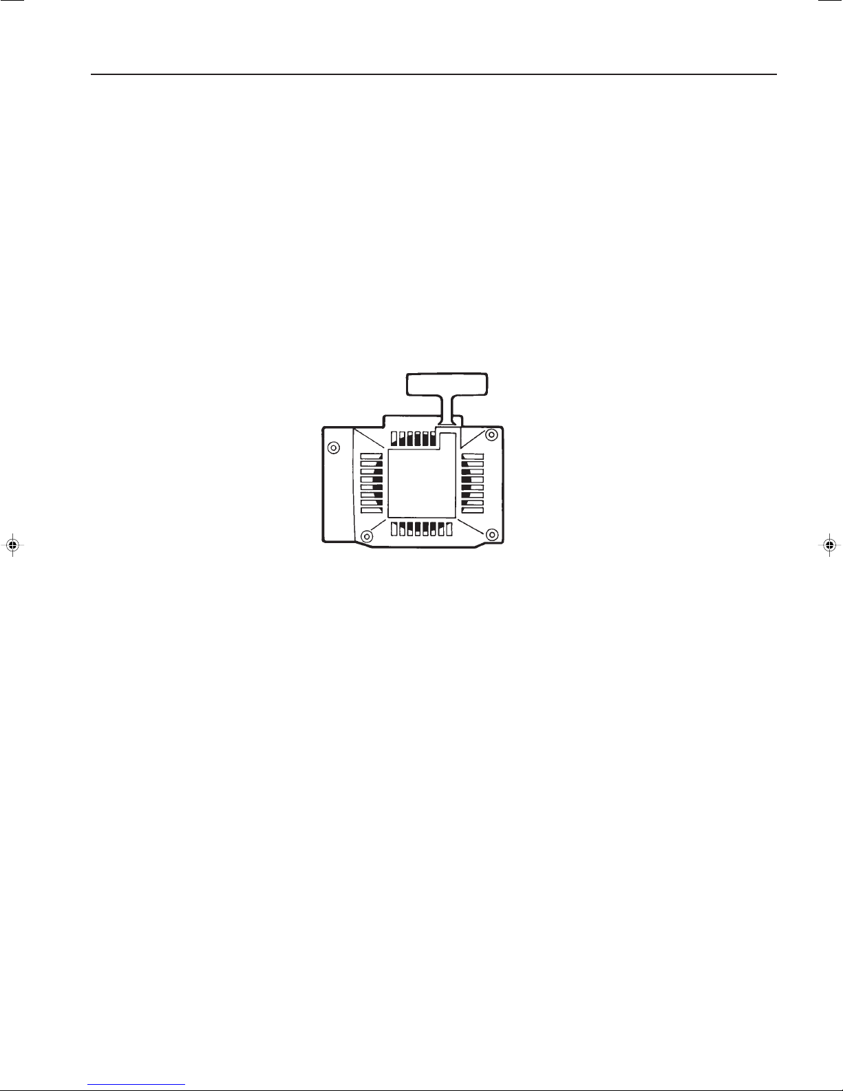
Starter
1.
Contents
Dismantling ________________________________ 4
Assembly _________________________________ 4
Replacing the drive pawls ____________________ 5
3
Page 5
1
Starter
!
WARNING!
Protective glasses should be worn when working on the starter to avoid injury to the
eyes if, for some reason, the return spring should fly out.
Dismantling
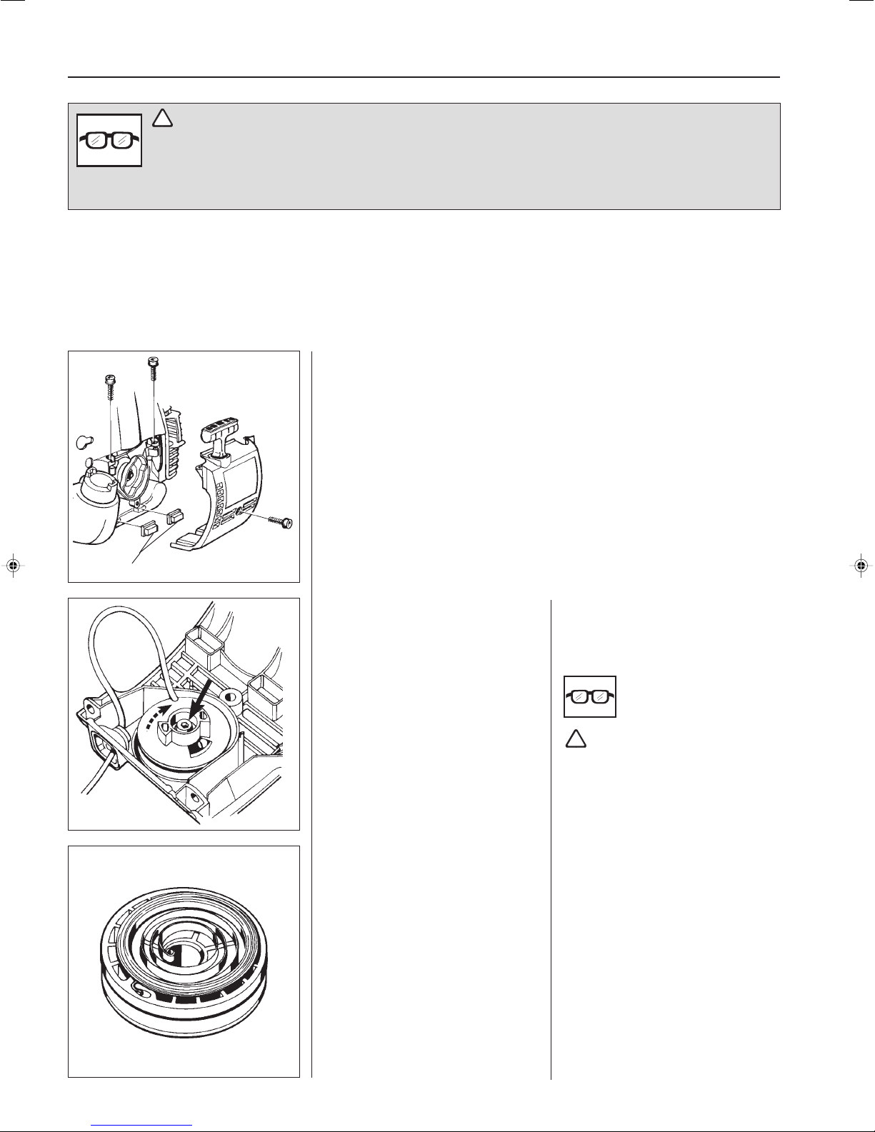
Remove the 3 bolts and lift out the starter.
NOTE!
Ensure the bushes (A) that guide the starter against the fuel tank are not lost.
A
Off-load the spring pressure.
Remove the bolt from the centre of the
starter pulley and lift off the starter
pulley.
Assembly
Clean all component parts and assemble in the reverse order as stated for
dismantling.
Off-load the spring pressure as described in the Workshop Manual.
Remove the bolt from the centre of the
starter pulley. Carefully lift the starter
pulley out of the starter housing.
!
WARNING!
Use protective glasses. The return
spring is tensioned in the starter
pulley and can fly out and cause
personal injury with negligent
handling.
Assembly
Clean all component parts before
assembling.
Replace the return spring/starter pulley
and starter cord if necessary.
NOTE!
The return spring and the starter pulley
are supplied assembled and are fitted in
the starter housing as a single unit.
Exercise care when opening the
packaging so that the spring does not
fly out.
4
Page 6
Starter
1
Fit the starter pulley.
Fit a new starter cord.
NOTE!
A new starter cord can be fitted without
the need of dismantling the starter!
Fit the starter handle.
Tension the return spring.
Check the spring tension.
Fit the starter on the engine body.
Do not forget the guide bushes for the
fuel tank.
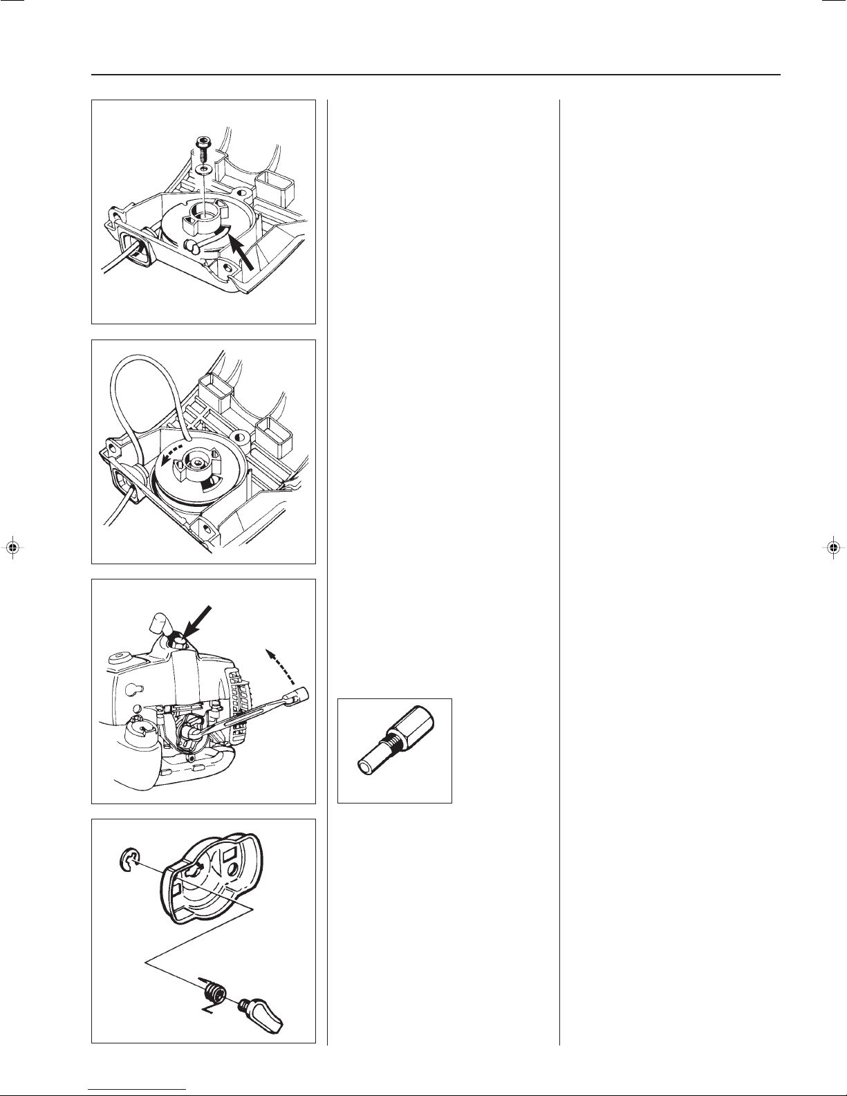
Lubricate the axle spindle with a little
grease and fit the starter pulley.
Position the washer and tighten the
bolt.
Fit a new starter cord. Slide it into the
groove on the starter pulley as shown
in the diagram and out through the cord
guide in the starter housing.
Make sure the knot on the end of the
cord is as small as possible!
Fit the starter handle as described in
the Workshop Manual.
Tension the return spring. Pull out the
starter cord completely and lift it up
through the cut-out in the starter pulley.
Now turn the starter pulley 6 turns
anticlockwise
Check the spring tension. With the cord
fully extended it should be possible to
turn the starter pulley
half turn.
.
at least a further
Replacing the drive
pawls
Dismantle the drive cup.
504 91 06-05
Remove the circlip and replace the
drive pawl or spring if damaged.
Replacing the drive
pawls
Fit the piston stop, No. 504 91 06-05 in
the spark plug hole and loosen the nut
holding the drive cup.
Remove the circlip holding the drive
pawl.
Lift off the drive pawl and spring for
replacement.
Assemble in the reverse order as
stated for dismantling.
5
Page 7

6
Page 8

Ignition system
2.
Contents
Dismantling 8
Assembly 9
7
Page 9
2
Ignition system
The engine is equipped with an electronic ignition
system with no moving parts. Consequently, a
faulty component cannot be repaired, but must be
replaced with a new component.
Dismantling
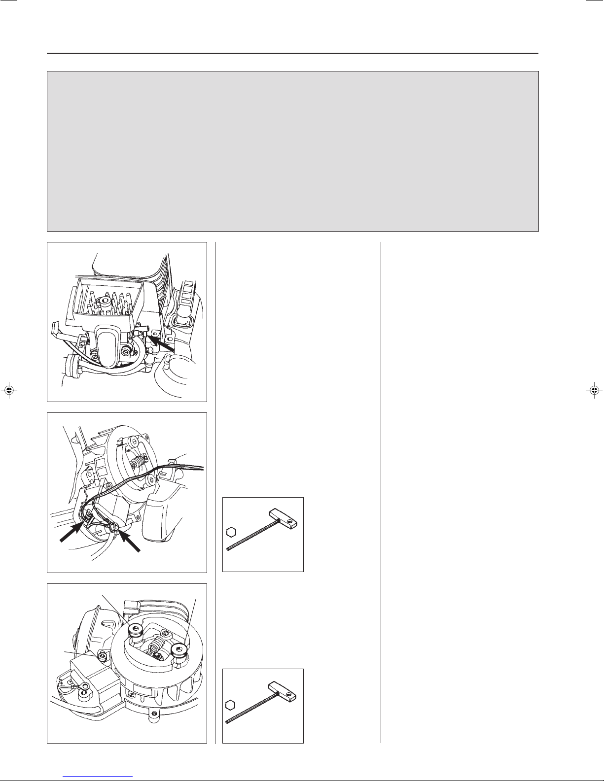
Dismantle the cylinder cover, the guard
over the muffler and the spark plug.
Unhook the throttle cable and remove
the bolts holding the clutch cover.
The ignition spark in an electronic ignition
system has a very short burn time and can
be judged to be weak and is at times difficult
to see when troubleshooting.
Dismantling
To gain access to the ignition system
the following components must be
dismantled:
Cylinder cover, guard over the muffler,
and the spark plug.
Unhook the throttle cable from the
carburettor.
Remove the clutch cover and loosen
the short-circuiting cable from the
ignition module.
504 90 00-02
B
A
Dismantle the ignition module and the
B
centrifugal clutch.
Remove the three bolts holding the
clutch cover.
Remove the complete clutch cover with
the shaft from the engine.
Loosen both the short-circuiting cable
lugs from the ignition module.
Remove the remaining bolts (A)
securing the ignition module as well as
the bolts (B) holding the centrifugal
clutch.
Lift off the clutch and ignition module.
8
504 90 00-03
Page 10
Ignition system
2
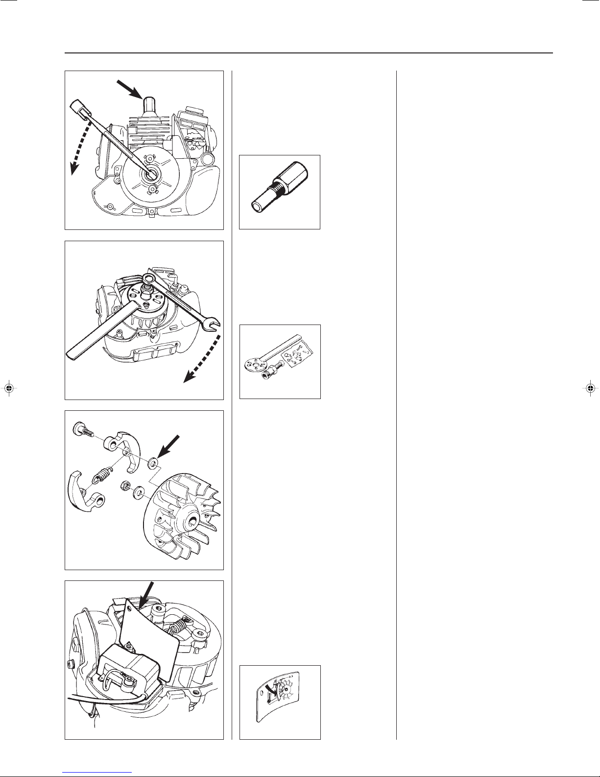
Fit the piston stop No. 504 91 06-05
and remove the nut holding the
flywheel.
504 91 06-05
Dismantle the flywheel.
Fit the piston stop No. 504 91 06-05 in
the spark plug hole.
Make sure the piston stop is screwed
down to the bottom.
Remove the nut holding the flywheel.
Dismantle the flywheel from the
crankshaft using puller No. 502 51 49-01.
Gently hit the puller screw with a
hammer if the flywheel sits hard on the
crankshaft.
502 51 49-01
Assembly
Check that the key and keyway show
no signs of damaged.
Fit the centrifugal clutch.
NOTE!
Do not forget the washers between the
flywheel and the centrifugal clutch.
Fit the ignition module and adjust the
spark gap to 0.3 mm.
Assembly
Check that the cast key in the flywheel
and the keyway in the crankshaft are
not damaged.
If the crankshaft has two keyways, the
flywheel should be fitted to the righthand keyway seen from the end of the
shaft.
Fit the centrifugal clutch.
NOTE!
Do not forget the washers between the
flywheel and the centrifugal clutch.
Fit the ignition module.
To simplify the adjustment of the spark
gap, do not fit the short-circuiting cables
yet. This should be set to 0.3 mm
between the permanent magnets in the
flywheel and the ignition module.
Now fit the short-circuiting cables and
other components in the reverse order
as stated for dismantling.
NOTE!
Do not forget the rubber bushes
between the clutch cover and fuel tank.
502 51 34-02
9
Page 11

10
Page 12
Fuel system
3.
Contents
Carburettor, dismantling _____________________ 12
Assembly ________________________________ 13
Throttle __________________________________ 13
Carburettor setting _________________________ 15
11
Page 13
3
Fuel system
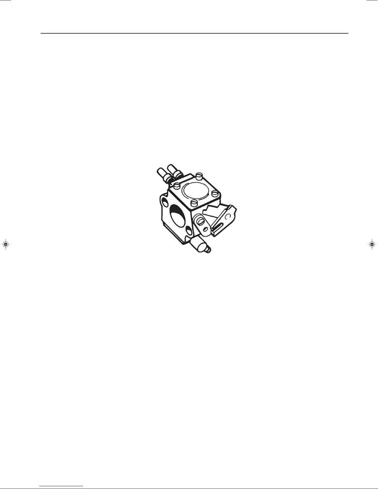
The fuel system comprises, in addition to the fuel
tank and the carburettor, also the air filter, fuel
filter and tank venting.
All these components interact so that the engine
receives the optimum mixture of fuel and to make
it as efficient as possible. Extremely small adjust-
4
Carburettor
Dismantling
Dismantle the cylinder cover and blow
out the carburettor compartment with
compressed air.
Dismantle the carburettor.
ments to the carburettor setting or air filter
blockage have a great effect on how the engine
runs and its efficiency.
The carburettor on our models can come from
several manufacturers, but the operation and
repair techniques are essentially the same.
Carburettor
Dismantling
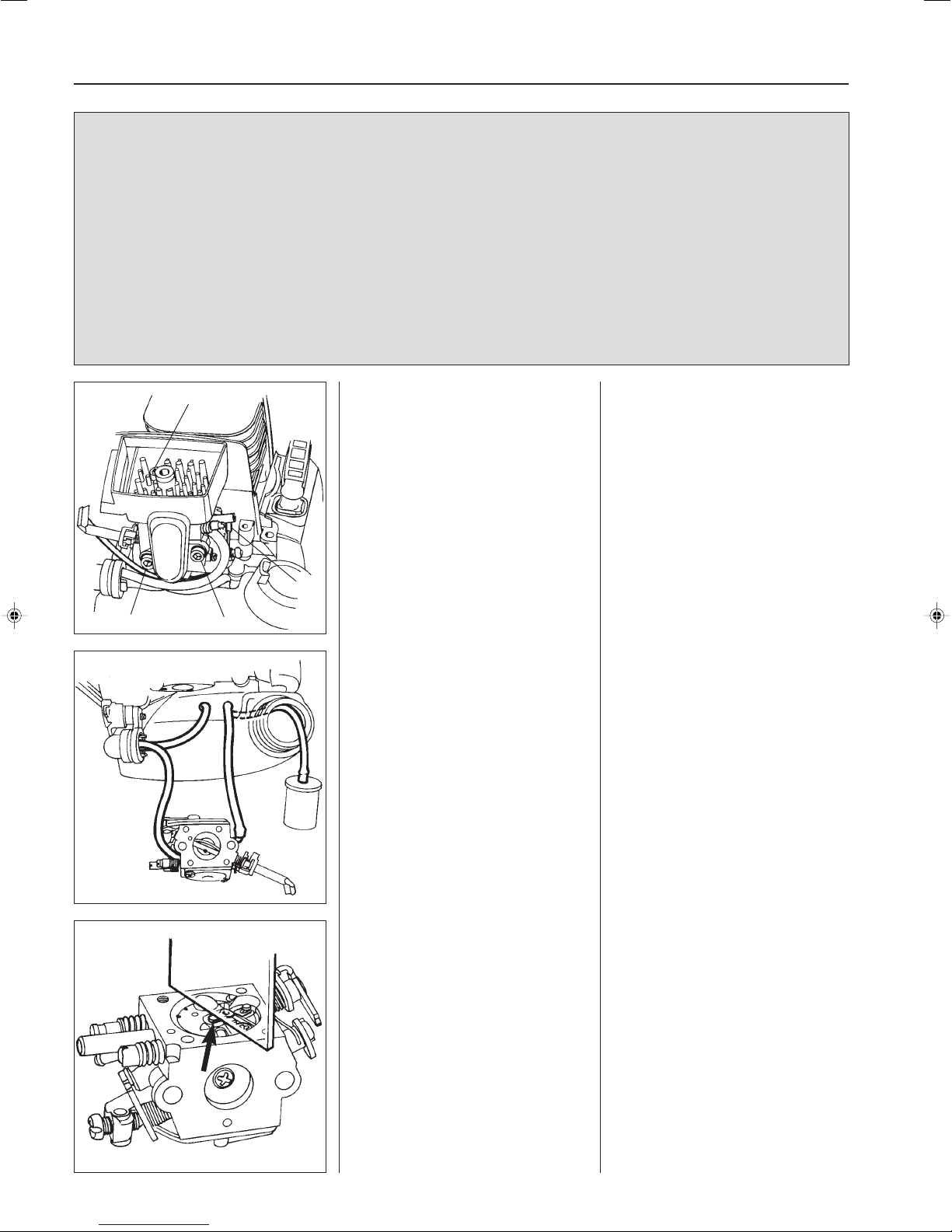
1. Remove the cylinder cover and
blow out the carburettor compartment with compressed air.
2. Disconnect the throttle cable from
the lever arm on the carburettor.
3. Loosen the carburettor bolts.
4. Remove the bolt holding the air filter
holder.
2
3
3
Lift off the carburettor and note how the
fuel hoses are fitted.
The carburettor is made by Zama.
The design, operation and servicing are
the same as for the Walbro carburettor.
Basic setting of the carburettor:
H=2
L=1
Lift off the carburettor and note how the
fuel hoses are fitted.
The carburettor is made by Zama.
It has the same design and operation
as Walbro, which means even the
servicing is carried out in the same way.
The lever arm should lie level with the
carburettor housing's gasket surface.
12
Page 14
Fuel system
Assembly
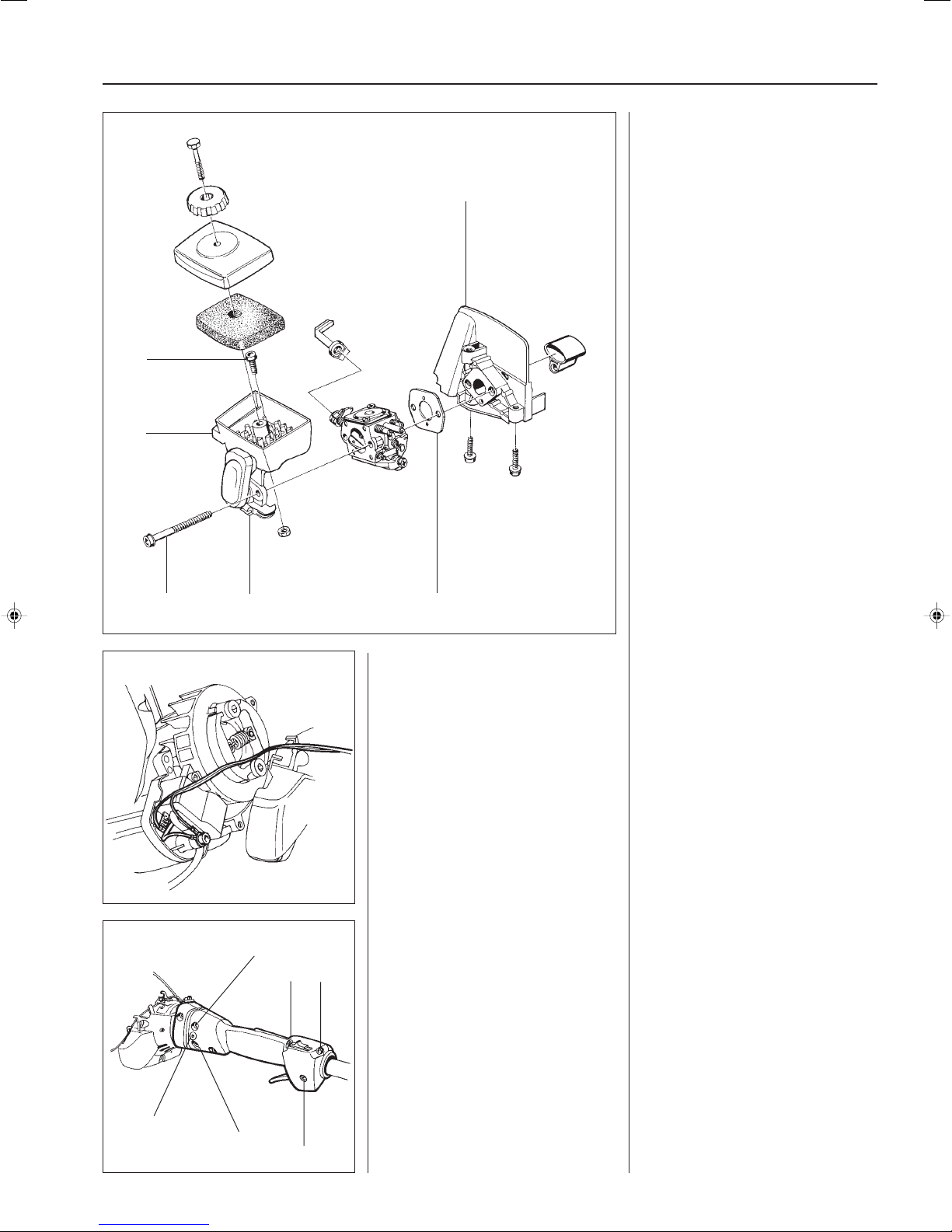
1. First fit the fuel hoses on the
carburettor.
4
5
1
NOTE!
The hose, with the fuel filter in the tank,
should be fitted on the carburettor's
inlet side (pump chamber).
2. Hold the air filter holder (1) in
position on the carburettor.
3. Slide in the carburettor bolts (2).
4. Place the gasket (3) in position and
secure the entire carburettor
package against the distance piece
(4). Tighten the carburettor bolts
crosswise.
NOTE!
Do not forget the bolt (5) that holds the air
filter holder against the distance piece.
5. Connect the throttle cable to the
lever arm on the carburettor.
Ensure the wire locates correctly in
the groove in the clutch cover and in
the guide on the air filter holder (6).
3
2
6
Throttle
Separate the engine body and clutch
cover.
Pull off the shaft with the throttle from
B
C
C
the clutch cover.
Remove the throttle from the shaft.
3
Assemble the other components in the
reverse order as stated for dismantling.
Throttle
In order to carry out the service and
repair work to the throttle efficiently it is
recommended that it is dismantled from
the engine and shaft.
Separate the engine body and the
clutch cover (see chapter “Ignition
system”).
Remove both bolts (A) (one on each
side).
Loosen the bolts (B) and pull off the
shaft with throttle from the clutch cover.
Loosen the 3 front bolts (C) (approx. 2
turns) that keep the throttle halves
together and pull the throttle off of the
shaft.
A
B
C
13
Page 15
3
Fuel system
Remove the bolts that hold together the
throttle and carefully separate the two
halves.
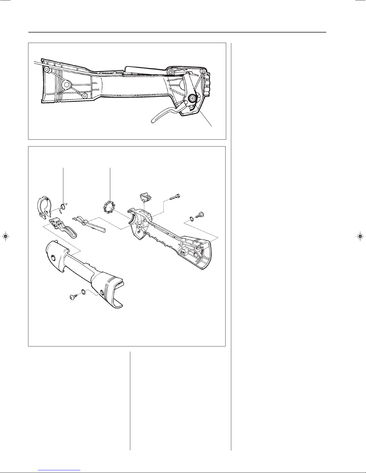
Note how the different components are
fitted. Pay special attention to which
way the return spring (A) is turned.
The stop contact can be pried off using
a small screwdriver if it needs to be
replaced.
A
Assembly of the throttle is carried out in
the reverse order as stated for disman-
A
B
tling.
Position the components in the left-
hand throttle half.
Make sure the return spring (A) is
turned the right way.
Check that the throttle cable and short-
circuiting cable are pressed down
correctly in respective channels so that
they are not crushed when the two
throttle halves are bolted together.
Do not forget to place the vibration
element (B) in position before the
throttle halves are put together. Lubricate the vibration element using soapy
water. This facilitates fitting the throttle
onto the shaft.
Fit together the throttle halves using the
5 bolts, but do not tighten them fully
until the throttle has been slid into
position on the shaft.
Assemble other components in the
reverse order as stated for dismantling.
14
Page 16
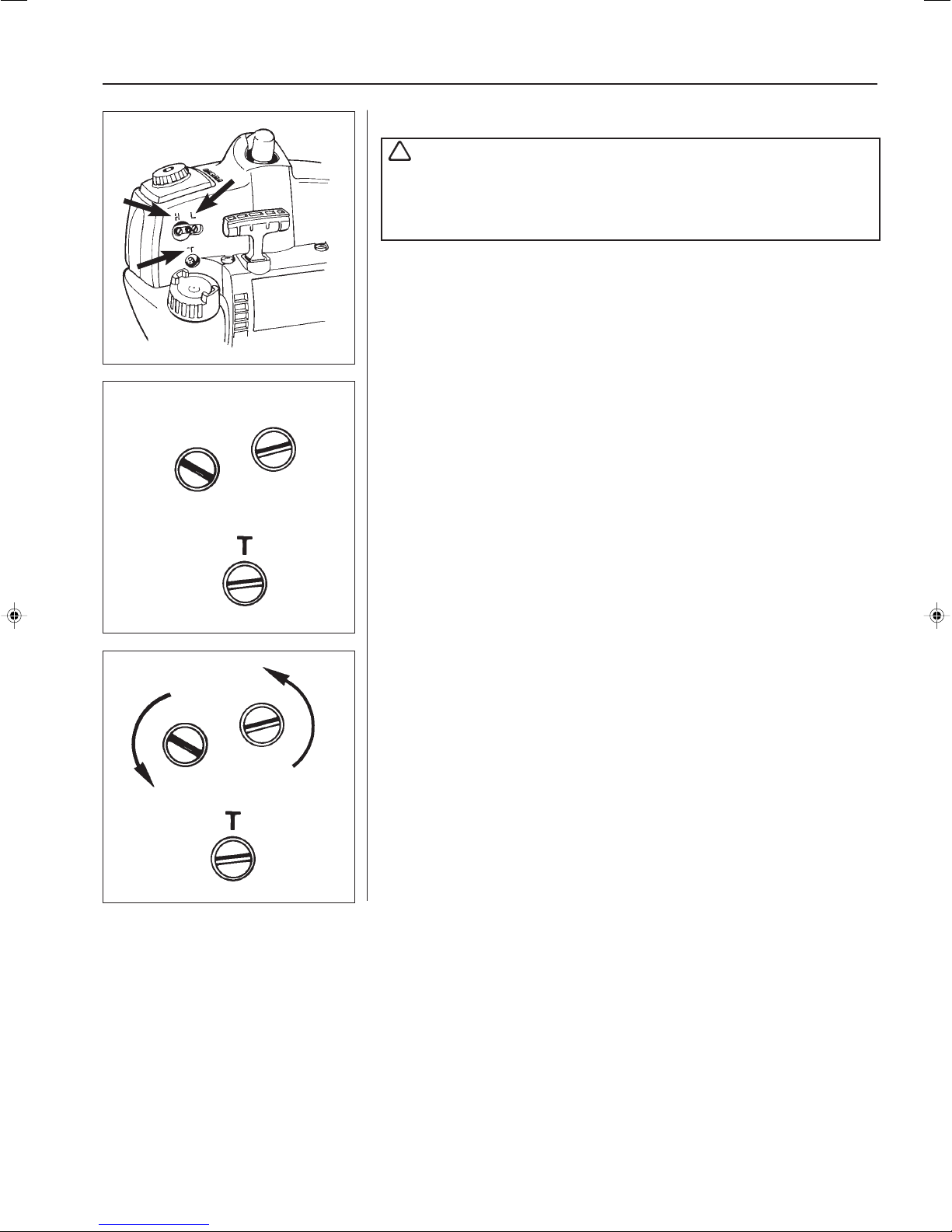
H
L
Fuel system
3
Carburettor setting
WARNING!
!
The clutch and clutch cover must, under all circumstances, be fitted
when testing running the engine after adjusting the carburettor.
Otherwise there is a risk that the clutch can become loose and cause
serious personal injury.
Function
The carburettor has the task of delivering a combustible air/fuel mixture to the
cylinder.
The amount
The mixture's composition
needles “H” and “L”.
The needles must be correctly adjusted so that the engine can give maximum
power at different speeds, run smoothly when idling and react quickly when accelerating.
The carburettor setting can vary a little depending on the humidity, temperature and
air pressure.
L = Low speed needle
H = High speed needle
T = Idle speed adjuster screw
● The fuel quantity in relation to the air flow permitted by the throttle opening is
adjusted by the L and H needles. Turning the needles clockwise gives a leaner
fuel mixture (less fuel) and turning them anticlockwise gives a richer fuel mixture
(more fuel). A
revs.
● The T-screw regulates the position of the throttle while the engine is idling.
Turning the screw clockwise gives a higher idling speed while turning it anticlockwise gives a lower idling speed.
of mixture is controlled by the throttle.
of petrol and air is controlled by using the adjustable
leaner
mixture gives
higher
revs while a
richer
mixture gives
less
H
L
Basic setting
The carburettor is set to its basic setting when test run at the factory. The basic
setting is “richer” than the optimal setting (the max speed is 600–800 r/min under
the recommended max. speed) and should be kept during the engine's first working
hours. Thereafter the carburettor should be finely adjusted.
Some carburettors are fitted with plastic sleeves with a limiter, so-called CARB- and
EPA-versions for USA. This type of carburettor can also be found on other markets
for certain models. When making carburettor adjustments as set out below the
adjustment range for the H and L needles can be too small. In such cases the
plastic sleeves must be removed (using pliers) in order for satisfactory adjustment
to be made.
Fine adjustment
Fine adjustment of the carburettor should be carried out after the engine has been
“run-in”.
● The air filter should be clean and the cylinder cover fitted when adjustments are
made.
First adjust the L needle, then the H needle and finally the idling speed's Tscrew.
The following speed recommendations apply:
Idling speed = 2 500 r/min.
15
Page 17
3
Fuel system
Max speed
Models 322 and 325 are equipped with an ignition system with
speed control 12 500 r/min.
When checking the speed on a trimmer no part of the cord
should be extended.
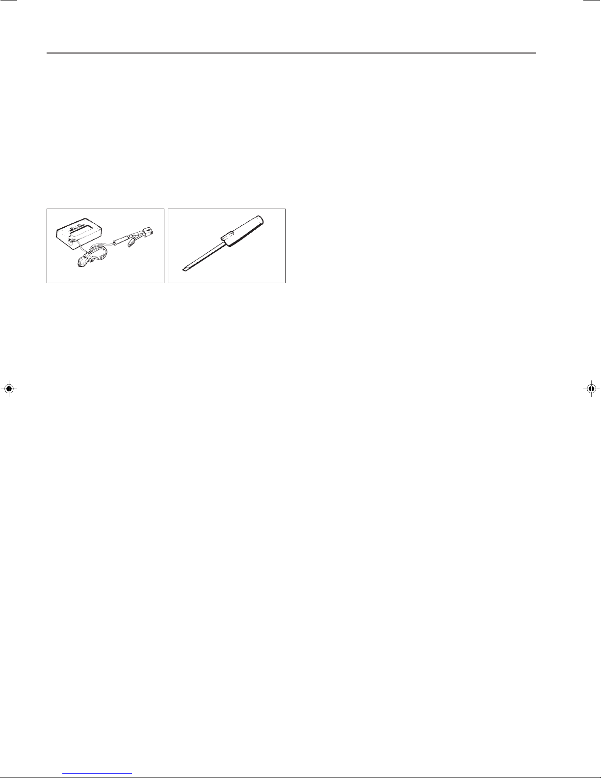
Check the speed using the tachometer 502 71 14-01.
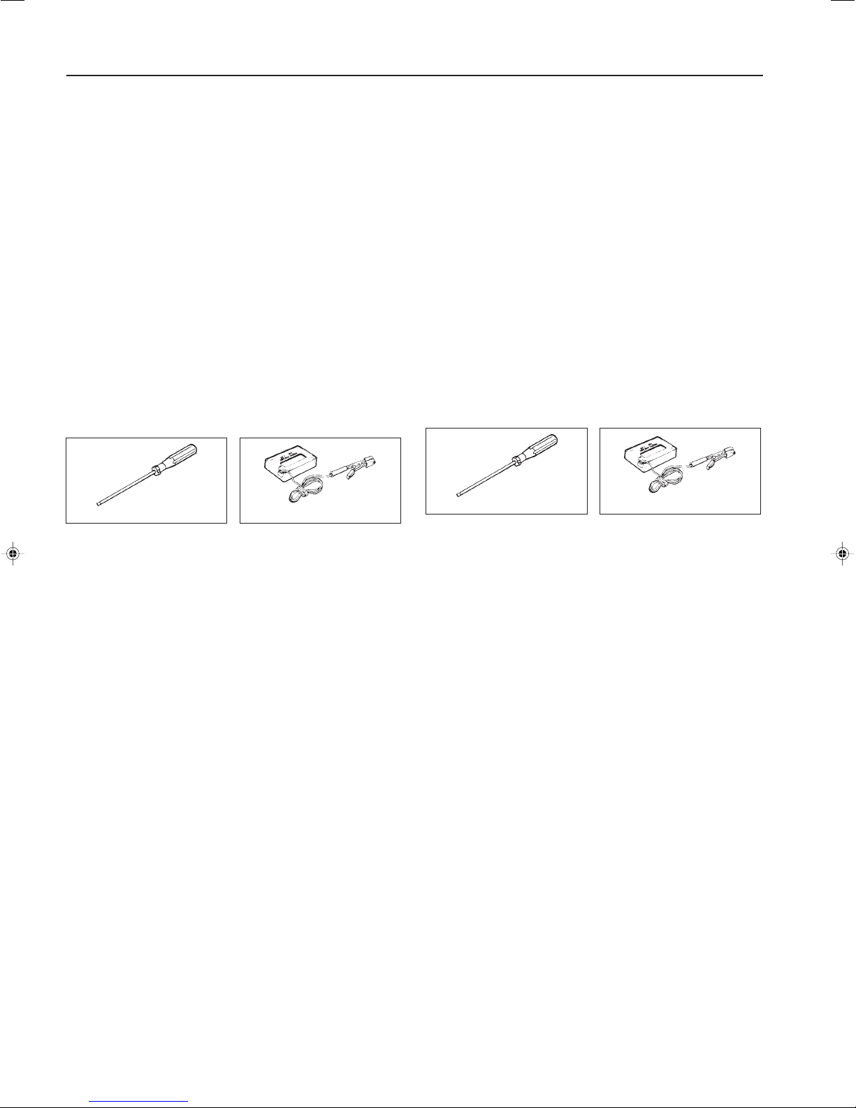
● Carefully screw in (clockwise) the L and H needles until they
bottom. Then screw out the H needle 2 1/2 turns and the
L needle 1 turn.
Use the special screwdriver 501 60 02-02.
● Start the engine and run warm for 10 minutes.
502 71 14-01 501 60 02-02
NOTE!
If the cutting equipment rotates while idling the T-screw should
be turned anticlockwise until it stops.
Low speed needle L
Find the highest idling speed by slowly turning the low speed
needle clockwise and anticlockwise. When the highest speed
has been found, turn the L needle 1/4 turn anticlockwise.
Idling speed T-screw
Let the engine idle for about 30 seconds or until the speed has
stabilised. Adjust the idling speed T-screw until the engine
idles without stopping.
● Turn the screw clockwise if the engine stops.
● Turn the speed anticlockwise to lower the speed.
Correctly adjusted carburettor
A correctly adjusted carburettor means that the engine accelerates without hesitation and it splatters a little at full throttle.
● A too lean adjusted L needle can cause starting difficulties
and bad acceleration.
● A too lean adjusted H needle results in lower power, bad
acceleration and/or damage to the engine.
● A too rich setting of the “L” and “H” needles give acceleration problems or a too low working speed.
High speed needle H (does not apply to engines with a
speed limiter)
NOTE!
If machines are equipped with a speed-controlled ignition system
the engine cannot be adjusted to max. speed, but must be set
according to the instructions for CARB/EPA (see page 17).
The high speed needle H affects the engine's power and speed.
A too lean H needle setting (H needle screwed in too far) gives
too little fuel to the engine resulting in damage to the engine.
Run the engine at full throttle for about 10 seconds. The H
needle is set correctly when the engine “splatters” a little.
If the muffler smokes heavily, at the same time as the engine
“splatters” a great deal, the setting is too “rich”. Turn the H
needle clockwise until you find the setting that sounds right.
NOTE!
A tachometer should always be used to find the optimal setting.
The recommended max. speed must not be exceeded.
16
Page 18
Fuel system
Carburettor in E-TECH and CARB-EPA designs
(CARB-EPA only applies in the USA)
On this type of carburettor the H and L needles can be adjusted within extremely
tight limits to, amongst others, comply with stringent demands with regard to the
hydrocarbon and nitrogen oxide content in the exhaust fumes.
The needles on these carburettors are fitted with plastic sleeves with limiters.
The engine must be loaded when making adjustments after replacing the needles
or the entire carburettor. This is achieved by fitting a Trimmy Fix with a trimming
cord of a specific length and diameter. The stated speed is then a great deal lower
than with “normal” carburettor adjustment when the engine runs unloaded at max
speed.
Adjustment must be carried out according to the instructions below after replacing
the needles or the entire carburettor on a CARB-EPA approved engine.
The Combi-guard or the spray guard must be fitted when adjusting the H needle.
3
After replacing the complete carburettor
1. Check that the plastic sleeve on the H needle is turned as
far as possible anticlockwise (richest fuel mixture). The
sleeve sits freely on the needle and can be turned without
affecting the needle's setting.
Do not change the L needle setting. This is adjusted at the
factory and the plastic sleeve is already fixed on the needle.
2. Fit four trimmer cords Ø 3.3 mm on a Trimmy Fix M10,
531 00 38-69 for models 322L, 322R, 325L, 325L-X, 325R-X.
Maybe the hole needs to be enlarged a little to make fitting
the trimmer cords easier.
3. Cut the trimmer cord to the right length (measure the length
to the edge of the Trimmy Fix).
Model 322L/R, 325L/L-X/R-X: 142 mm
Fit the Trimmy Fix on the machine.
Model 322C should be used with Trimmy Hit VI and its
standard cord (Ø 2.0 mm). Cut the cord ends so that they
are 146 mm long.
4. Start the engine. Adjust the idling speed T screw if necessary.
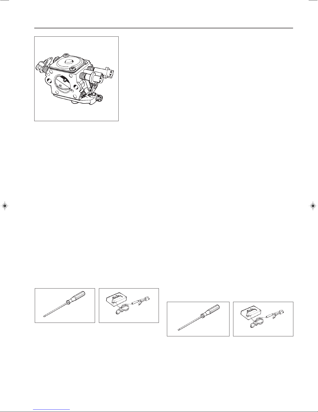
5. Use screwdriver 531 00 48-63 to adjust the H needle. The
blade is 2 mm wide and goes through the plastic sleeve
and only adjusts the needle.
Adjust the H needle so that the max. speed 8400 ±
200 r/min is set.
Use the tachometer 502 71 14-01 to check the speed.
After replacing only the H needle
1. Turn the L needle as far as possible anticlockwise (richest
fuel mixture).
2. Remove the plastic sleeve on the H needle and unscrew the
needle.
3. Carefully screw in the new H needle to the bottom and then
loosen it 2 1/2 turns.
4. Press a new plastic sleeve on the H needle down to the first
stop. The sleeve can now be turned without turning the needle.
5. Turn the plastic sleeve as far as possible anticlockwise
(richest fuel mixture) without turning the needle.
6. Fit four trimmer cords Ø 3.3 mm on a Trimmy Fix M10,
531 00 38-69 for models 322L, 322R, 325L, 325L-X, 325R-X.
Maybe the hole needs to be enlarged a little to make fitting
the trimmer cords easier.
7. Cut the trimmer cord to the right length (measure the length
to the edge of the Trimmy Fix).
Model 322L/R, 325L/L-X/R-X: 142 mm
Fit Trimmy Fix on the machine.
Model 322C should be used with Trimmy Hit VI and its
standard cord (Ø 2.0 mm). Cut the cord ends so that they
are 146 mm long.
8. Start the engine. Adjust the idling speed T screw if necessary.
9. Use screwdriver 531 00 48-63 to adjust the H needle. The
blade is 2 mm wide and goes through the plastic sleeve and
only adjusts the needle.
Adjust the H needle so that the max. speed 8400 ±
200 r/min is set.
Use the tachometer 502 71 14-01 to check the speed.
531 00 48-63
6. Run the engine warm for 2–3 minutes.
7. Check that the max speed is still 8400 ± 200 r/min. Adjust
the H needle if necessary.
8. Check that the plastic sleeve on the H needle is still turned
as far as possible anticlockwise (richest fuel mixture).
9. Press in the plastic sleeve using a punch (Ø 5 mm).
The basic setting of the carburettor is now complete. Further
fine adjustment, within the limits that the plastic sleeves on the
needles permit, can be necessary.
502 71 14-01
531 00 48-63
10.Run the engine warm for 2–3 minutes.
11.Check that the max speed is still 8400 ± 200 r/min. Adjust
the H needle if necessary.
12.Check that the plastic sleeve on the H needle is still turned
as far as possible anticlockwise (richest fuel mixture).
13.Press in the plastic sleeve using a punch (Ø 5 mm).
The basic setting of the carburettor is now complete. Further
fine adjustment, within the limits that the plastic sleeves on the
needles permit, can be necessary.
502 71 14-01
17
Page 19
3
Fuel system
After replacing the H and L needles
1. Remove the plastic sleeves from both needles and screw
out the needles.
2. Carefully screw the new needles in until they bottom.
Screw out the L needle 1 turn.
Screw out the H needle 2 1/2 turns.
3. Press the new plastic sleeves on the needles until the first
stop. The sleeves can still be turned without the needles
turning.
4. Turn the plastic sleeve on the L needle as far as possible
clockwise (leanest fuel mixture).
5. Start the engine and let it idle.
6. Use the screwdriver 531 00 48-63 to adjust the L needle.
The blade is 2 mm wide and goes through the plastic
sleeve and only adjusts the needle.
Adjust the L needle so that the highest idling speed is
obtained.
Use the tachometer 502 71 14-01 to check the speed.
7. Check that the plastic sleeve on the L needle is still turned
as far as possible clockwise (leanest fuel mixture).
531 00 48-63
8. Press the plastic sleeve on the L needle using a punch
(Ø 5 mm).
Now turn the L needle as far as possible anticlockwise
(richest fuel mixture).
9. Turn the plastic sleeve on the H needle as far as possible
anticlockwise (richest fuel mixture).
10. Fit four trimmer cords Ø 3.3 mm on a Trimmy Fix M10,
531 00 38-69 for models 322L, 322R, 325L, 325L-X, 325R-X.
Maybe the hole needs to be enlarged a little to make fitting
the trimmer cords easier.
11.Cut the trimmer cord to the right length (measure the length
to the edge of the Trimmy Fix).
Model 322L/R, 325L/L-X/R-X: 142 mm
Fit the Trimmy Fix on the machine.
Model 322C should be used with Trimmy Hit VI and its
standard cord (Ø 2.0 mm). Cut the cord ends so that they
are 146 mm long.
12.Start the engine. Adjust the idling speed T screw if necessary.
13.Use screwdriver 531 00 48-63 to adjust the H needle. The
blade is 2 mm wide and goes through the plastic sleeve
and only adjusts the needle.
Adjust the H needle so that the max. speed 8400 ± 200 r/min
is set.
Use the tachometer 502 71 14-01 to check the speed.
(Does not apply to model 225H60/H75).
14.Run the engine warm for 2–3 minutes.
15.Check that the max speed is still 8400 ± 200 r/min. Adjust
the H needle if necessary.
16.Check that the plastic sleeve on the H needle is still turned
anticlockwise as far as possible (richest fuel mixture).
17.Press in the plastic sleeve using a punch (Ø 5 mm).
502 71 14-01
The basic setting of the carburettor is now complete. Further
fine adjustment, within the limits that the plastic sleeves on the
needles permit, can be necessary.
After replacing only the L needle
1. Turn the H needle as far as possible clockwise (leanest fuel
mixture).
2. Remove the plastic sleeve on the L needle and unscrew the
needle.
3. Carefully screw in the new L needle to the bottom and then
loosen it 1 turn.
4. Press a new plastic sleeve on the L needle down to the first
stop. The sleeve can now be turned without turning the
needle.
5. Turn the plastic sleeve as far as possible clockwise (leanest
fuel mixture).
6. Start the engine and let it idle.
7. Use the screwdriver 531 00 48-63 to adjust the L needle.
The blade is 2 mm wide and goes through the plastic
sleeve and only adjusts the needle.
531 00 48-63
Adjust the L needle so that the highest idling speed is
obtained.
Use the tachometer 502 71 14-01 to check the speed.
8. Check that the plastic sleeve on the L needle is still turned
as far as possible clockwise (leanest fuel mixture).
9. Press the plastic sleeve on the L needle using a punch
(Ø 5 mm).
The basic setting of the carburettor is now complete. Further
fine adjustment, within the limits that the plastic sleeves on the
needles permit, can be necessary.
502 71 14-01
18
Page 20
Centrifugal clutch
4.
Contents
Dismantling 20
Assembly 20
Replacing the clutch drum and drive axle 21
19
Page 21
4
Centrifugal clutch
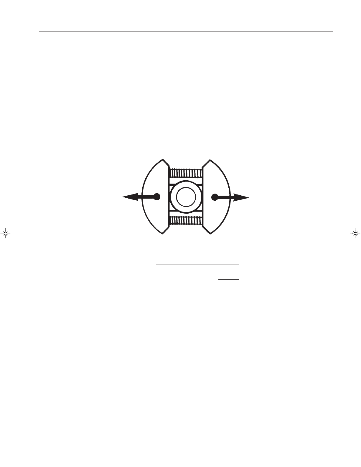
The centrifugal clutch has the task of transferring
the power from the engine to the cutting equipment's drive axle. As the name implies, it works
according to a centrifugal principle.
This means the clutch's friction shoes are thrown
outwards towards the clutch drum at a certain
engine speed. When the friction against the drum
is sufficiently great it drives the drive axle at the
same speed as the engine.
Dismantling
Dismantle the clutch by following the
instructions in the chapter “Ignition
system”.
Some slipping occurs between the clutch and
the clutch drum when accelerating as well as
in the reversed situation when the cutting
equipment jams. Thereby abnormal load
changes on the crankshaft are prevented.
The engagement speed has been carefully
tested so that the engine can idle without the
cutting equipment's drive axle rotating.
Dismantling
The centrifugal clutch is bolted to the
flywheel.
Follow the detailed instructions in the
chapter “Ignition system” when the
clutch is dismantled.
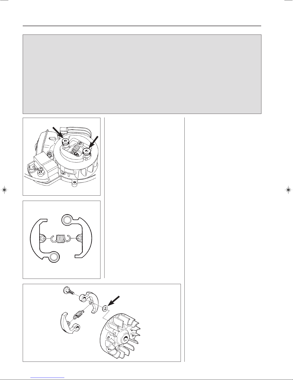
Twist open the clutch and inspect the
components with regard to wear or
damage.
Twist open the clutch.
Inspect the components with regard to
wear or damage.
Pay close attention to the ends of the
springs, which in addition to wear can
also show signs of crack formation in
the material.
Assembly
Put together the clutch shoes with the
springs.
NOTE!
Both clutch shoes should be replaced
even if only one of the shoes shows
signs of heavy wear. This is to prevent
engine vibration due to imbalance in
the clutch.
20
Bolt the clutch on the flywheel. Do not
forget the washers between the
flywheel and the clutch shoes.
Page 22
Centrifugal clutch
4
Replacing the clutch
drum and drive axle
Separate the shaft from the clutch
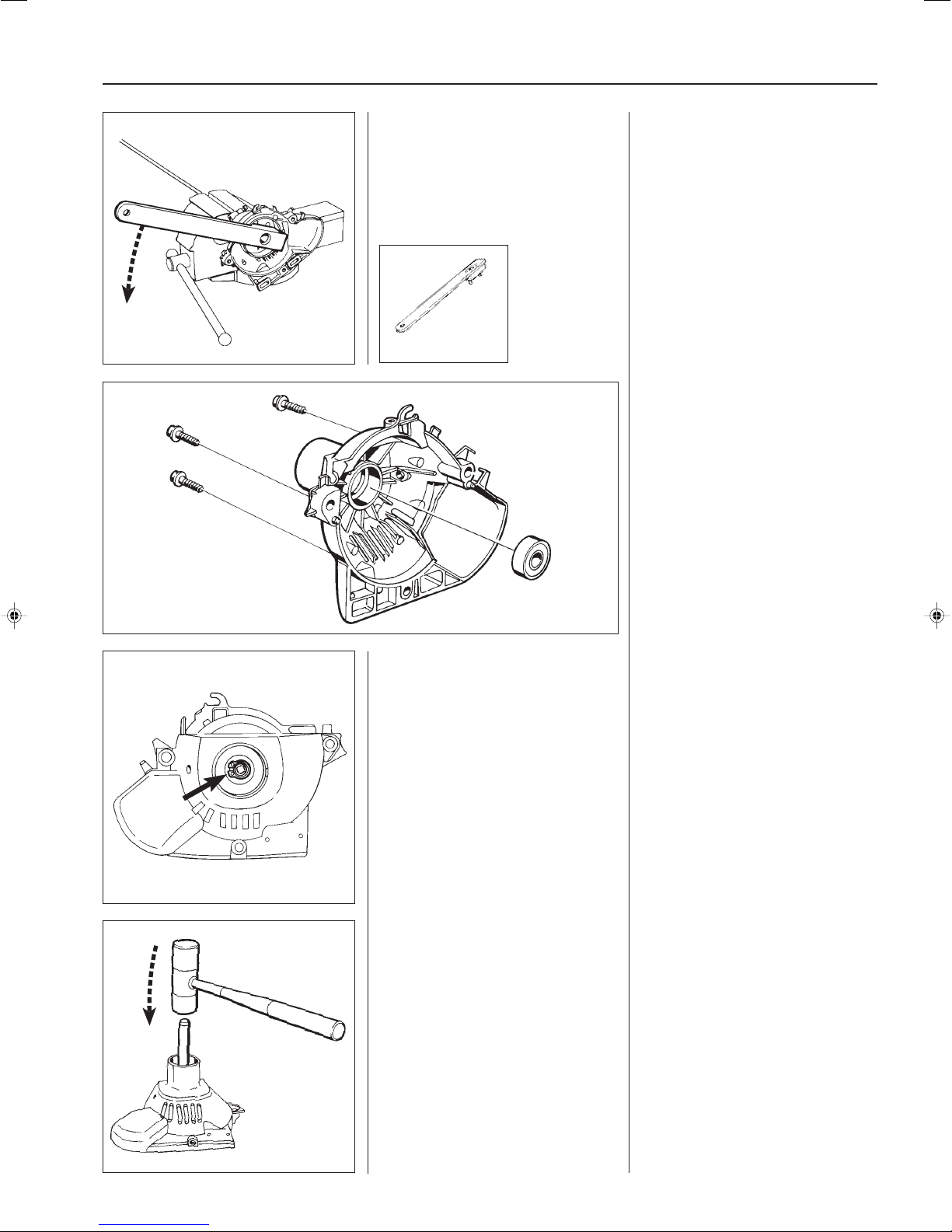
cover.
Dismantle the clutch drum using the
tool 502 52 16-01.
502 52 16-01
Replacing the clutch
drum and drive axle
Separate the shaft from the clutch
cover.
Pull off the clutch cover complete with
the drive axle and clutch drum.
The drum is screwed on the drive axle
and can be dismantled using the tool
502 52 16-01.
If the diameter exceeds Ø 64.1 mm, the
clutch drum should be replaced.
The bearing journalling the clutch drum
in the clutch cover is glued in position
using Loctite. To replace the bearing
the cover can be heated to approx.
70°C by using a hot air gun so that the
glue releases.
Dismantle the bearing using a suitable
punch and hammer.
NOTE!
Dismantle the shaft's securing clamp
and rubber insert in the clutch cover so
that these are not damaged when
heating the cover.
Model 322C
Dismantle the clutch cover and remove
the shaft's securing components from
the cover.
Remove the circlip.
Knock off the clutch drum.
Replace the bearing and fit the other
components in the reverse order as
stated for dismantling.
Assembly is carried out in the reverse
order as stated for dismantling.
Use Loctite intended for mounting
bearings when fitting the bearings in
the clutch cover.
Model 322C
Dismantle the clutch cover from the
shaft.
Remove the shaft's securing components from the clutch cover.
Remove the circlip holding the clutch
drum's axle spindle with the bearing.
Now knock off the clutch drum using a
suitable punch and hammer.
The bearing is replaced in the same
way as described above.
Assembly takes place in the reverse
order as stated for dismantling.
21
Page 23

22
Page 24
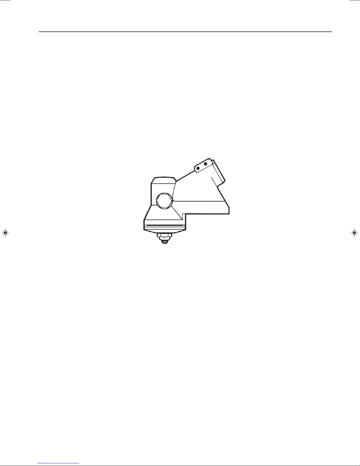
Angle gear
5.
Contents
Dismantling _______________________________ 24
Assembly ________________________________ 25
23
Page 25
5 Angle gear
The angle gear has two purposes:
The first is to gear down the engine's high speed
to better suit the lower speed a blade or trimmer
requires to work efficiently.
Secondly, the angle gear contributes towards the
Dismantling
Remove the angle gear from the shaft.
Remove the circlips holding the bear-
ings on the input respective output
axles.
operator's working stance so that it is comfortable and at the same time efficient. In
other words, the power from the engine via
the drive axle shall be angled so that the
cutting equipment works parallel with the
ground.
Dismantling
1. Dismantle the cutting equipment
and its guard.
2. Loosen the bolt holding the angle
gear on the shaft and remove the
angle gear.
3. Remove the circlips holding the
bearings on the output axle (illustrated) respective on the input axle
by using circlip pliers.
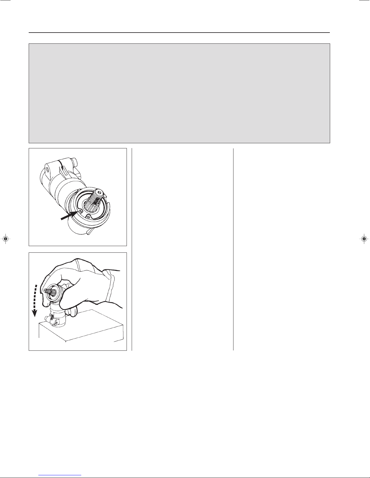
Heat the entire angle gear to approx.
110°C and first dismantle the input axle
and then the output axle.
Heat the entire angle gear to approx.
110°C using a hot air gun.
Hit the angle gear against a wooden
block so that the input axle with bearing
falls out.
Now lift out the output axle.
Wear protective gloves.
24
Page 26
Angle gear
5
D
A
C
B
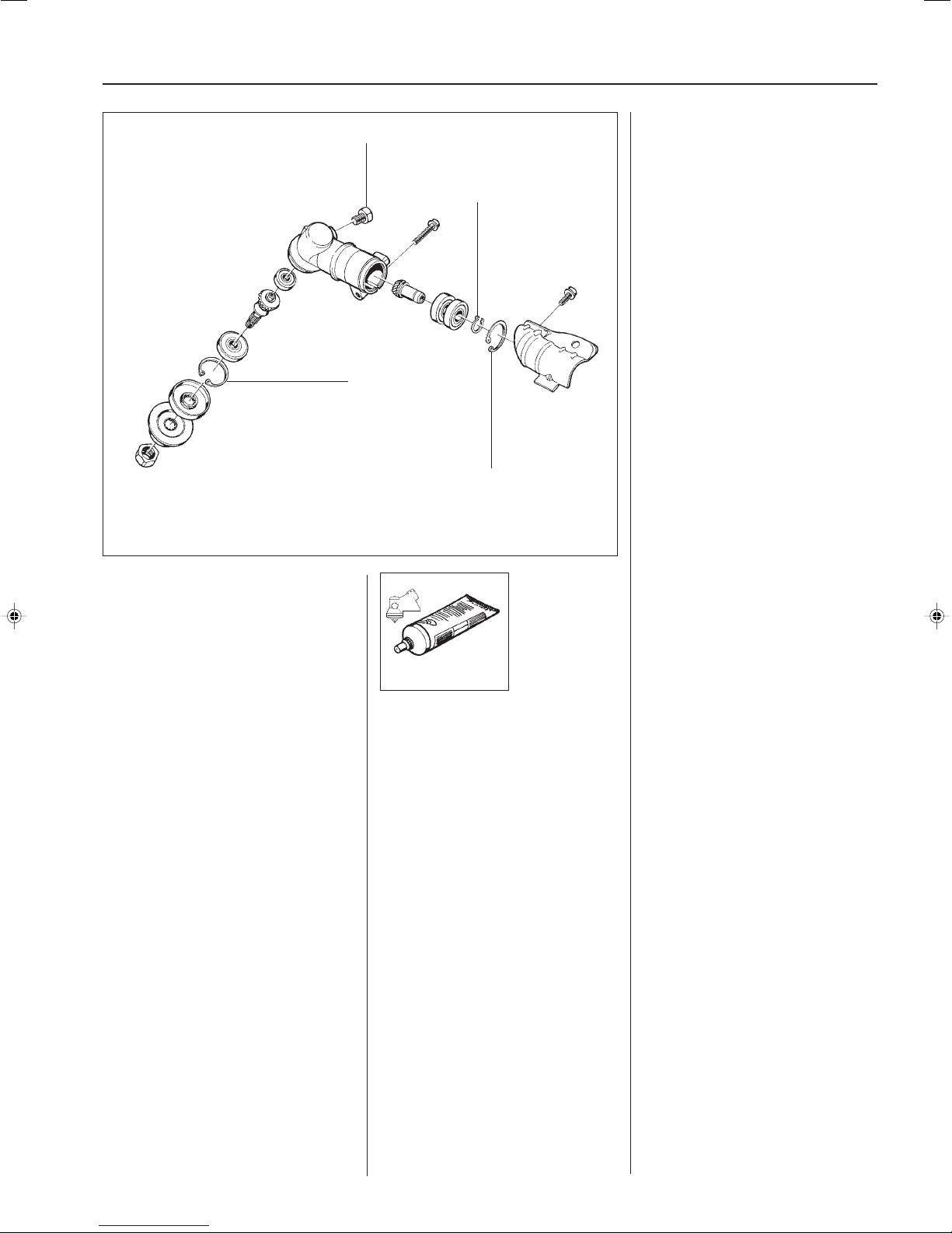
Assembly
Clean all component parts and replace
those that are worn or damaged.
Fit new bearings on respective axles. It
is easier if the bearing is heated to
approx. 110°C by using a hot air gun .
NOTE!
Do not forget the circlip (A) that holds
the bearing on the input axle.
Heat the gear housing to approx.
110°C and insert the output axle first
and then the input axle.
Make sure the bearing bottoms in its
seating.
Fit the circlips (B) and (C). Make sure
they sit correctly in their grooves.
Other components are fitted in the
reverse order as stated for dismantling.
NOTE!
Do not forget to fill the gear to approx.
3/4 full using gearbox grease
503 97 64-01 once the plug (D) has
been removed.
503 97 64-01
25
Page 27

26
Page 28

Cylinder and piston
6.
Contents
Dismantling _______________________________ 28
Assembly ________________________________ 29
27
Page 29
6
Cylinder and piston
The cylinder and piston are two components
that are exposed to the most strain in the
engine. For example, they should withstand
high speed, large changes in heat and high
pressure. In addition, they should withstand
wear. Despite the hard working conditions,
serious cylinder and piston failures are quite
unusual. Some of the reasons behind this are
Dismantling
Dismantle all components around the
cylinder including the distance piece
fitted to the carburettor.
the new coating materials in the cylinder bore,
new lubricants and improved manufacturing
techniques.
Cleanliness is extremely important when
servicing these components. We therefore
recommend that the cylinder and the area
around it is cleaned thoroughly before it is
dismantled from the crankcase.
Dismantling
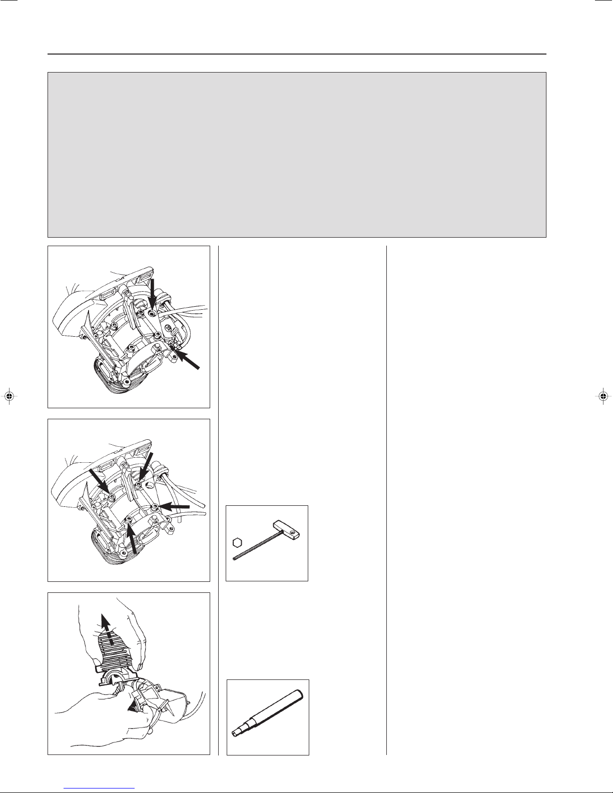
Dismantle the following components:
Cylinder cover, muffler grille, muffler
with heat guard, starter and spark plug.
Fold back the fuel tank.
Now remove the 2 bolts holding the
distance piece against the crankcase.
Remove the distance piece with the
carburettor attached.
Remove the bolts holding the cylinder.
504 90 00-02
Pull off the cylinder and dismantle the
piston and connecting rod.
Remove the 4 bolts holding the cylinder
on the crankcase.
Pull the cylinder straight up without
turning it. If it is turned, there is a risk of
the piston ring breaking.
A sealant has been used on the base of
the cylinder instead of a gasket.
Dismantle the piston from the connecting rod (see the Workshop Manual if
necessary).
28
505 38 17-05
Page 30
Cylinder and piston
6
Assembly
Clean and inspect the piston and
cylinder. Check the rubber intake
manifold with regard to crack formation
or other damage.
Clean the sealant from the crankcase
and fit the piston on the connecting rod.
Assembly
Before the piston and cylinder and fitted
parts should be cleaned and inspected
as instructed in the Workshop Manual.
Check that the rubber intake manifold
between the cylinder and distance
piece has not cracked or shows signs
of other damage that can cause leaks.
Clean any sealant or grease from the
crankcase.
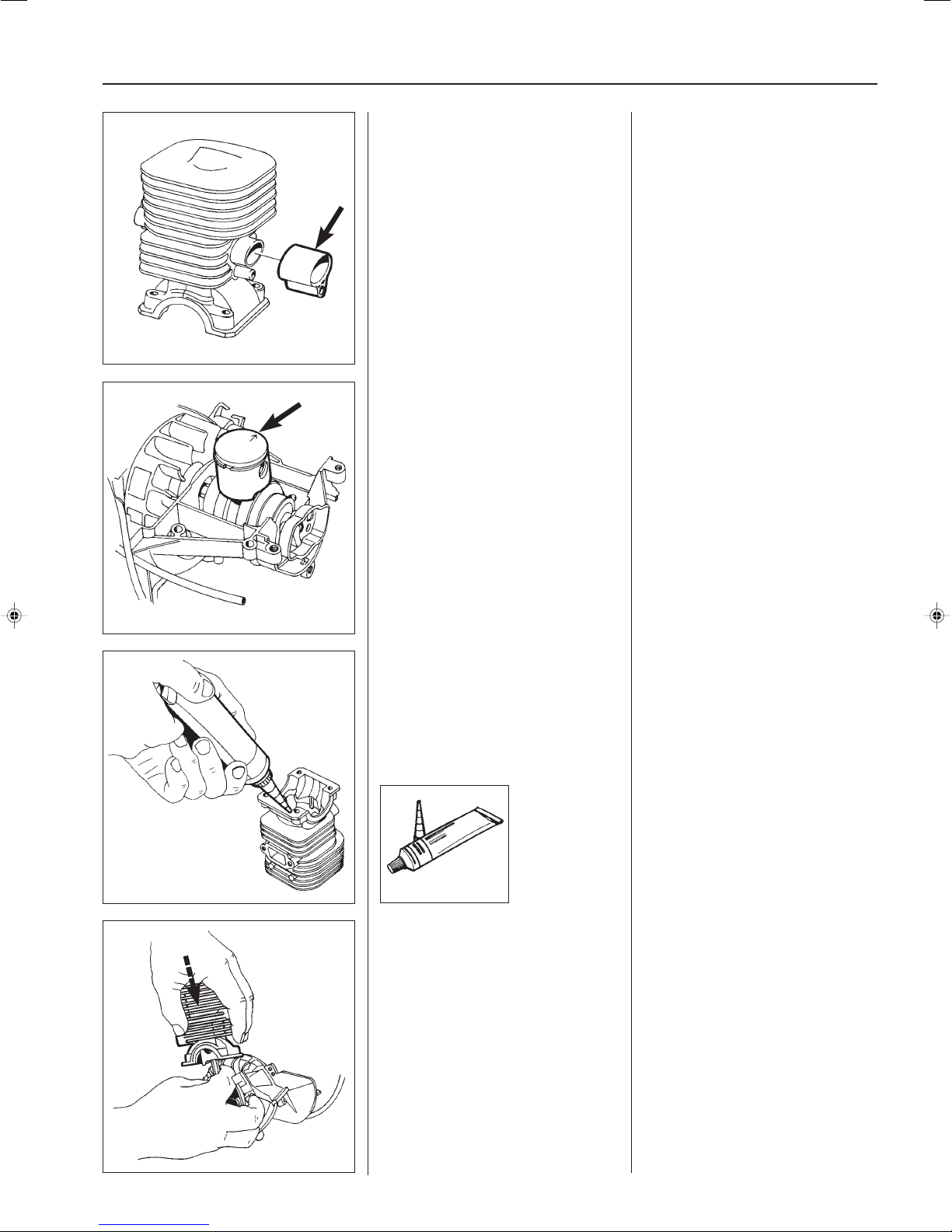
Fit the piston on the connecting rod so
that the arrow on top of the piston
points towards the exhaust port. See
the instructions in the Workshop
Manual.
Clean the contact surface on the base
of the cylinder and apply a narrow
string of sealant No. 503 26 70-01 to
the sealing surface.
503 26 70-01
Carefully slide down the cylinder over
the piston and tighten the 4 bolts
crosswise.
Clean the old sealant and grease from
the contact surfaces on the base of the
cylinder.
Apply a narrow string (1 – 1.5 mm) of
sealant No. 503 26 70-01 to the contact
surface.
NOTE!
The sealant does not need to be
applied to the bearing's contact surface.
Lubricate the piston with a few drops of
oil and carefully slide the cylinder over
the piston.
NOTE!
Do not turn the cylinder as the piston
ring can easily break.
Tighten the 4 bolts crosswise.
Fit other components in the reverse
order as stated for dismantling.
29
Page 31

30
Page 32
Crankshaft and crankcase
7.
Contents
Dismantling _____________________________________ 32
Assembly ______________________________________ 32
31
Page 33
7
Crankshaft and crankcase
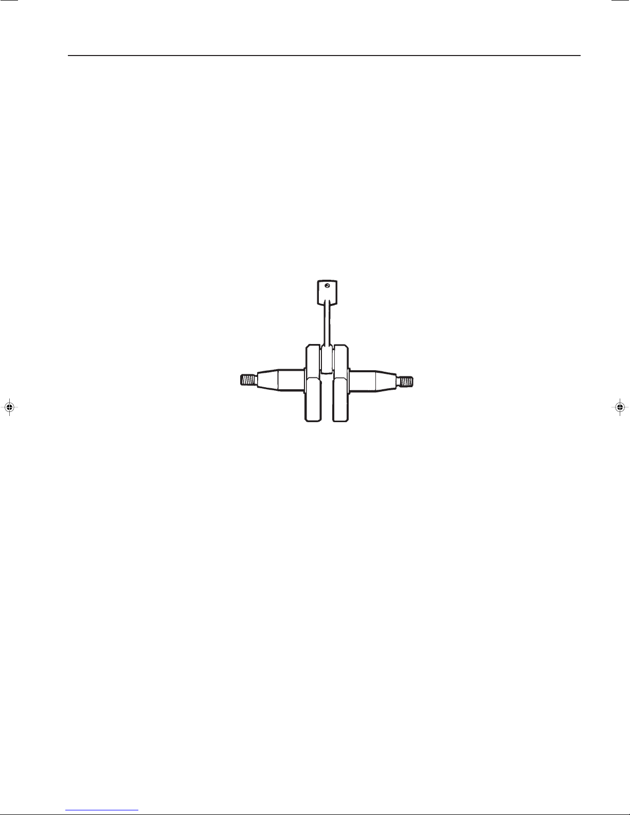
The task of the crankshaft is to transfer the up and
down motion of the piston to rotation. To do this
requires a stable design withstanding immense pressure, rotational and bending strain as well as high
rotational speed. In addition the connecting rod is
exposed to large acceleration and retardation forces as
it moves between top and bottom dead centres. This
puts special demands on the bearings that must
withstand quick changes in load. Besides, the bearing's roller retainer also must cope with high temperatures and friction. Therefore it is extremely important
when servicing, to check the roller retainer for cracking, wear and miscolouration due to overheating.
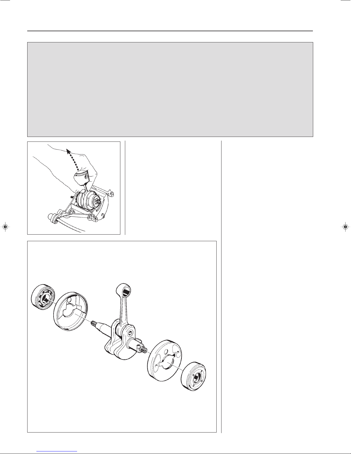
Dismantling
Dismantle all components so that only
the crankcase and crankshaft remain.
Now lift the crankshaft out of the
crankcase.
The crankshaft is journalled in the crankcase on
heavy-duty ball bearings. In addition to the
journalling point for the crankshaft, the crankcase acts as scavenging pump for the fuel/air
mixture when this is "sucked" from the carburettor and is forced into the cylinder's combustion
chamber. The crankcase must be perfectly sealed
so as not to affect this pump function. There
cannot be any leakage either from the crankshaft
or between the crankcase halves or between the
crankcase and the cylinder.
Always replace the sealing rings and gaskets
when servicing the crankcase.
Dismantling
Dismantle all components so that only
the crankcase and crankshaft remain.
Refer to respective sections if necessary for detailed information.
Now lift the crankshaft out of the
crankcase.
Remove the bearings (sliding fit) and
the spacers.
Assembly
Check the crankshaft as set out in the
section “Inspecting the crankshaft” in
the Workshop Manual.
Clean the contact surfaces in the
crankcase.
Fit new bearings on the crankshaft with
the open side facing in towards the
crank disc.
Lubricate the big end bearings with a
few drops of engine oil and position the
crankshaft in the crankcase.
Fit all other components in the reverse
order as stated for dismantling.
Refer to respective sections in the
Workshop Manual if necessary.
Leak test the crankcase in accordance
the instructions in the Workshop
Manual.
32
Page 34

101 90 19-26
2018W43
 Loading...