

Husqvarna 240 F, 265 RX User Manual

Operator’s manual (EPA)
240F 240R 250R
252RX 265RX
Please read the operator’s manual carefully and make sure you
understand the instructions before using the machine.
EEEEnnnngggglllliiiisssshh
hh
Symbols
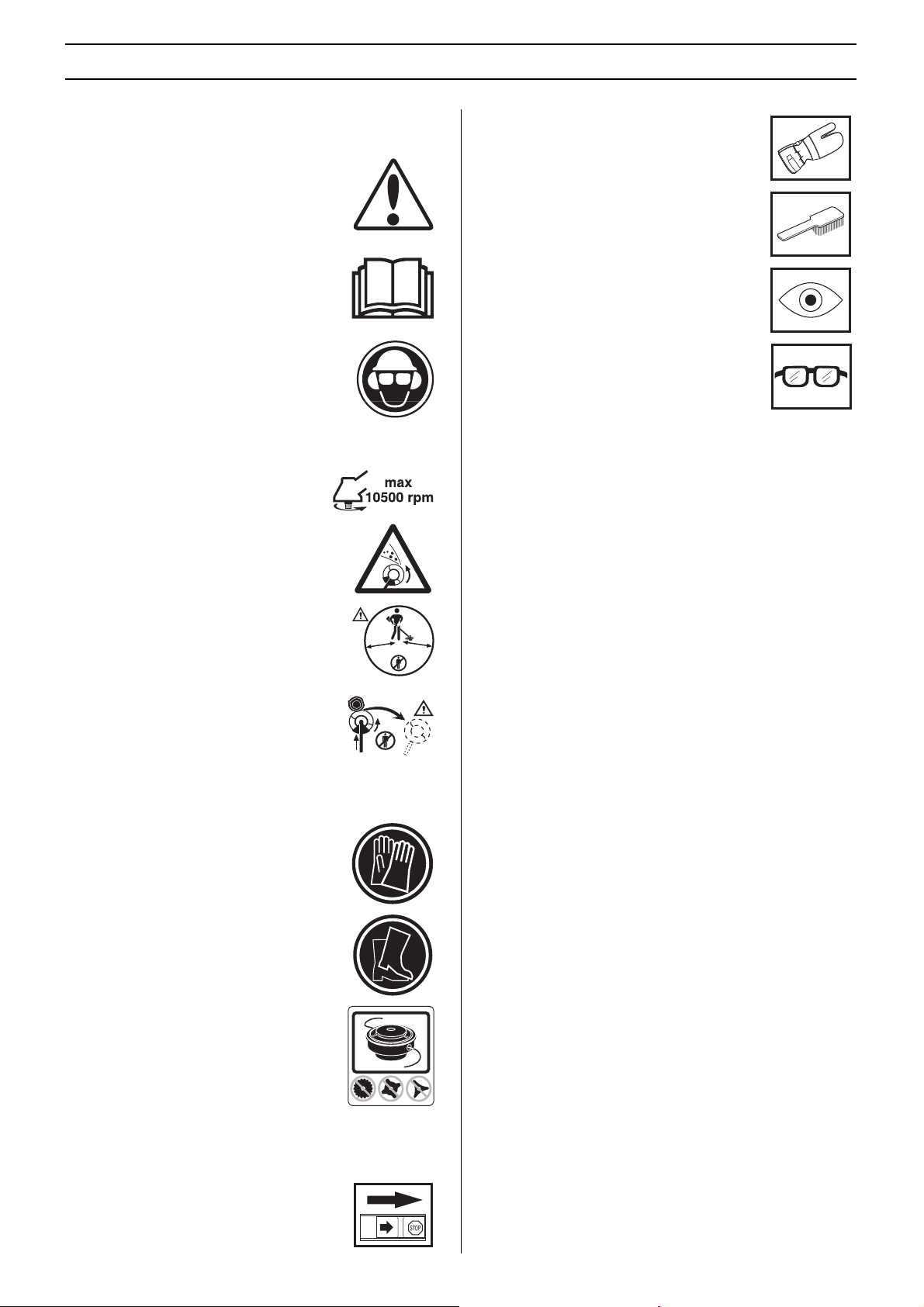
WARNING! Clearing saws, brushcutters and
trimmers can be dangerous! Careless or
incorrect use can result in serious or fatal
injury to the operator or others.
Please read the operator’s manual carefully
and make sure you understand the
instructions before using the machine.
Always wear:
• A protective helmet where there is a risk
of falling objects
• Hearing protection
• Approved eye protection
KEY TO SYMBOLS
Always wear approved protective gloves.
Regular cleaning is required.
Visual check.
Approved eye protection must always be
used.
Max. speed of output shaft, rpm
Watch out for thrown objects and ricochets.
The operator of the machine must ensure,
while working, that no persons or animals
come closer than 15 metres.
Machines fitted with saw blades or grass
blades can be thrown violently to the side
when the blade comes into contact with a
fixed object. The blade is capable of
amputating an arm or leg. Always keep
people and animals at least 15 metres from
the machine.
Always wear approved protective gloves.
15 m
50FT
50FT
15 m
Wear sturdy, non-slip boots.
Only use non-metallic, flexible cutting
attachments, i.e. trimmer heads with
trimmer cord.
Other symbols/decals on the machine refer to special
certification requirements for certain markets.
Switch off the engine by moving the stop
switch to the STOP position before carrying
out any checks or maintenance.
2 –
English
TWC
CONTENTS
Contents Note the following before starting:
KEY TO SYMBOLS
Symbols ....................................................................... 2
CONTENTS
Contents ...................................................................... 3
Note the following before starting: ................................ 3
INTRODUCTION
Dear customer! ............................................................ 4
WHAT IS WHAT?
What is what on the clearing saw? (240R) ................... 5
What is what on the clearing saw? (240F).................... 6
What is what on the clearing saw? (250R) ................... 7
What is what on the clearing saw? (252RX)................. 8
What is what on the clearing saw? (265RX)................. 9
GENERAL SAFETY PRECAUTIONS
Important ...................................................................... 10
Personal protective equipment ..................................... 10
Machine ′ s safety equipment ........................................ 11
Cutting equipment ........................................................ 14
ASSEMBLY
Assembling the handlebar and throttle (240R, 250R)... 16
Fitting the handlebar (240F, 252RX) ............................. 16
Transport position, handlebar (240R, 240F, 250R,
252RX).......................................................................... 16
Fitting the handlebar (265RX)....................................... 17
Assembling the cutting equipment ............................... 17
Fitting a blade guard, grass blade and grass cutter ..... 17
Fitting the blade guard and saw blade ......................... 18
Fitting the trimmer guard and trimmer head Trimmy SII 18
Fitting other guards and cutting attachments ............... 19
Adjusting the harness and clearing saw ...................... 19
Standard harness ........................................................ 19
Triobalance harness ..................................................... 20
FUEL HANDLING
Fuel safety ................................................................... 21
Fuel .............................................................................. 21
Fueling ......................................................................... 22
STARTING AND STOPPING
Check before starting ................................................... 23
Starting and stopping ................................................... 23
WORKING TECHNIQUES
General working instructions ....................................... 25
MAINTENANCE
Carburetor .................................................................... 29
Muffler .......................................................................... 31
Cooling system ............................................................ 31
Air filter ......................................................................... 32
Bevel gear .................................................................... 32
Spark plug .................................................................... 33
Maintenance schedule ................................................. 34
TECHNICAL DATA
Technical data .............................................................. 35
FEDERAL EMISSION CONTROL WARRANTY
STATEMENT
YOUR WARRANTY RIGHTS AND OBLIGATIONS ..... 38
• Please read the operator’s manual carefully.
• Long-term exposure to noise can result in permanent
hearing impairment. So always use approved hearing
protection.
Maintenance, replacement, or repair of the emission control
devices and system may be performed by any nonroad
engine repair establishment or individual.
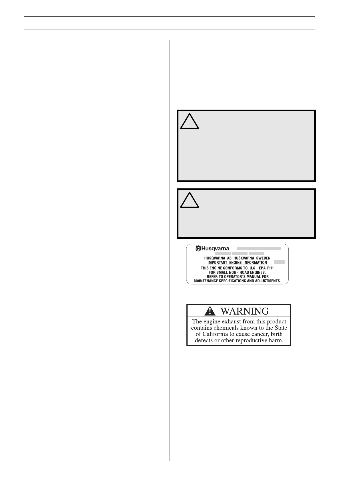
WARNING! Under no circumstances may the
design of the machine be modified without
!
the permission of the manufacturer. Always
use genuine accessories. Non-authorized
modifications and/or accessories can result
in serious personal injury or the death of the
operator or others.
Your warranty may not cover damage or
liability caused by the use of non-authorized
accessories or replacement parts.
WARNING! A clearing saw, brushcutter or
trimmer can be dangerous if used
!
incorrectly or carelessly, and can cause
serious or fatal injury to the operator or
others. It is extremely important that you
read and understand the contents of this
operator’s manual.
This label certify that the product has been certified in
accordance with American exhaust requirements EPA 1.
English
– 3

INTRODUCTION
Dear customer!
Congratulations on your choice to buy a Husqvarna product! Husqvarna is based on a tradition that dates back to 1689, when the
Swedish King Karl XI ordered the construction of a factory on the banks of the Huskvarna River, for production of muskets. The
location was logical, since water power was harnessed from the Huskvarna River to create the water-powered plant. During over
300 years of continuous operation, the Husqvarna factory has produced a lot of different products, from wood stoves to modern
kitchen appliances, sewing machines, bicycles, motorcycles etc. In 1956, the first motor driven lawn mowers appeared, followed
by chain saws in 1959, and it is within this area Husqvarna is working today.
Today Husqvarna is one of the leading manufacturers in the world of forest and garden products, with quality as our highest priority.
We develop, manufacture and market high quality motor driven products for forestry and gardening as well as for building and
construction industry.
Your purchase gives you access to professional help with repairs and service whenever this may be necessary. If the retailer who
sells your machine is not one of our authorized dealers, ask for the address of your nearest servicing dealer.
It is our wish that you will be satisfied with your product and that it will be your companion for a long time. Think of this operator ′ s
manual as a valuable document. By following its ′ content (using, service, maintenance etc) the life span and the second-hand value
of the machine can be extended. If you ever lend or sell this machine, make sure that the borrower or buyer gets the operator ′ s
manual, so they will also know how to properly maintain and use it.
Thank you for using a Husqvarna product.
Husqvarna AB has a policy of continuous product development and therefore reserves the right to modify the design and
appearance of products without prior notice.
For customer assistance call: 704-921-7000 or contact us at our website: www.husqvarna.com
4 –
English
WHAT IS WHAT?
8
2
3
5
6
7
9
1
15
4
16
22
28
18
17
1
19
19
4
4
21
26
29
27
23
25
24
What is what on the clearing saw? (240R)
1 Blade
2 Grease filler cap, bevel gear
3 Bevel gear
4 Cutting attachment guard
5 Shaft
6 Handlebar
7 Throttle control
8 Stop switch
9 Throttle lock
10 Support eyes for harness
11 Cylinder cover
12 Starter handle
13 Fuel tank
14 Choke control
15 Handle adjustment
16 Locking screw (support cup)
17 Support flange
18 Support cup
19 Drive disc
20 Trimmer head
21 Socket spanner
22 Operator’s manual
23 Transport guard
24 Allen key
25 Carburettor screwdriver
26 Locking pin
27 Harness
28 Locking nut
29 Gearbox grease
30 Air filter
English
– 5

WHAT IS WHAT?
8
2
3
4
5
7
15
9
10
13
14
11
26
19
21
22
20
23
12
6
16
17
1
18
27
4
25
24
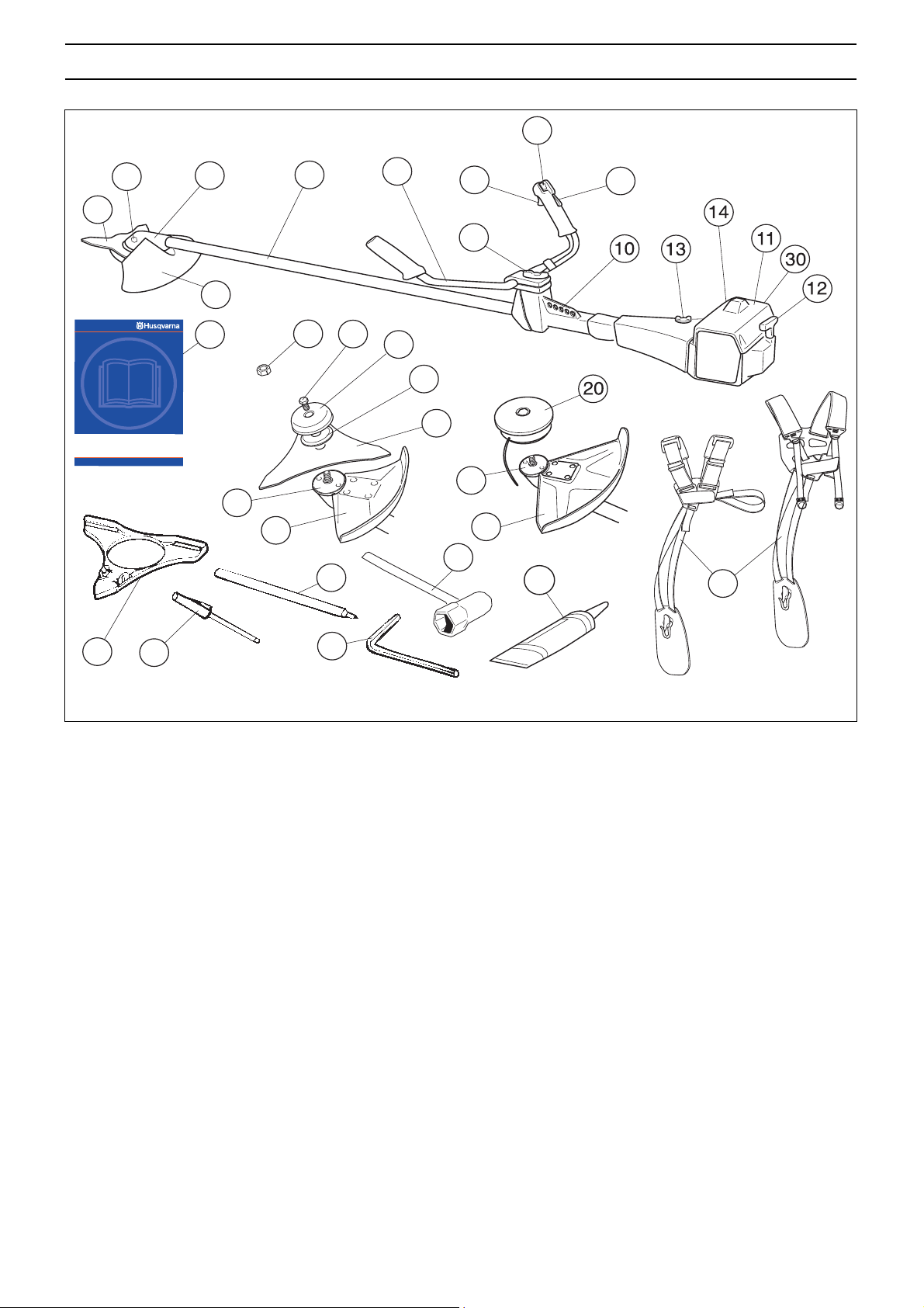
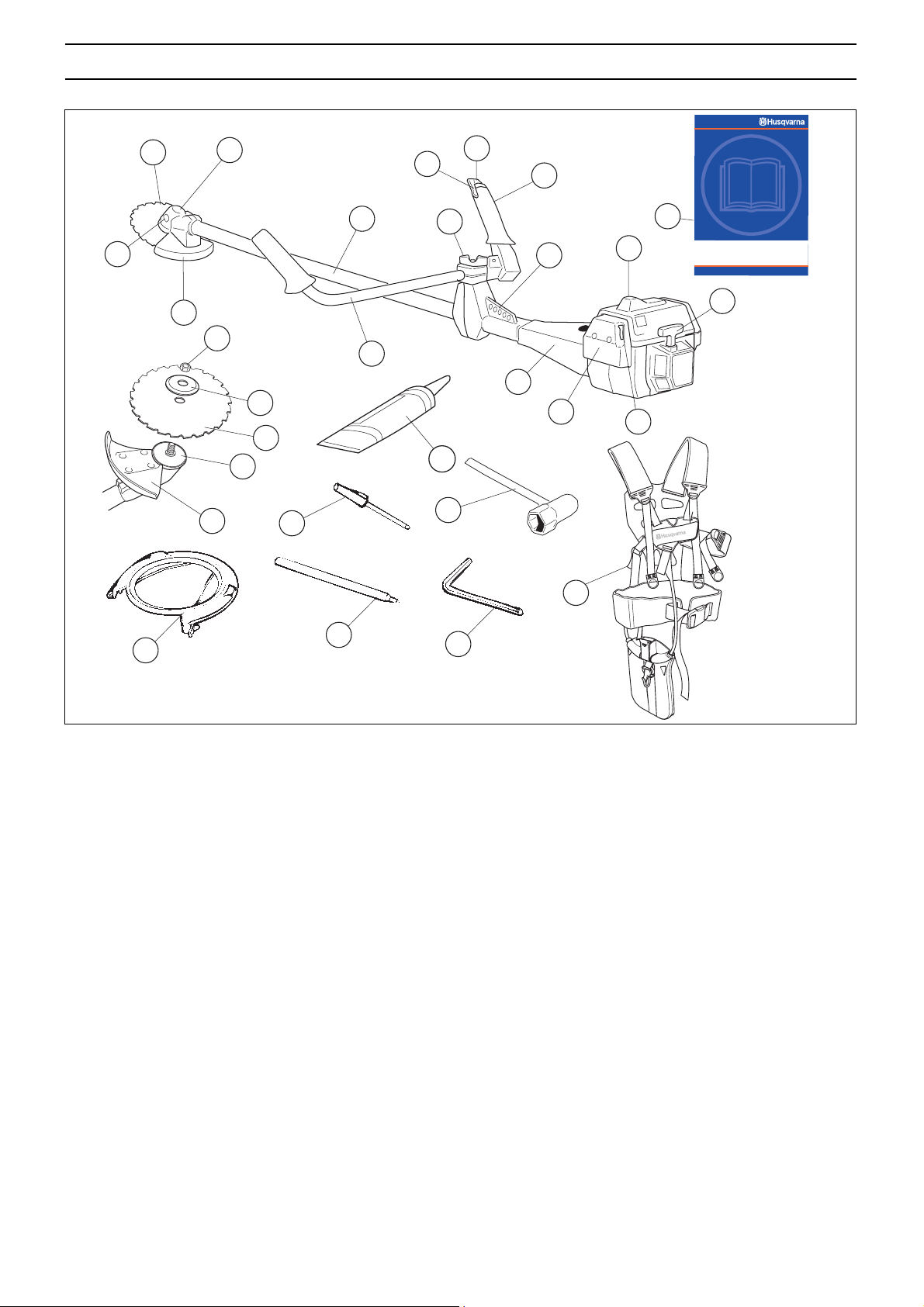
What is what on the clearing saw? (240F)
1 Blade
2 Grease filler cap, bevel gear
3 Bevel gear
4 Cutting attachment guard
5 Shaft
6 Handlebar
7 Throttle control
8 Stop switch
9 Throttle lock
10 Support eyes for harness
11 Cylinder cover
12 Starter handle
13 Fuel tank
14 Choke control
15 Handle adjustment
16 Locking nut
17 Support flange
18 Drive disc
19 Socket spanner
20 Operator’s manual
21 Transport guard
22 Allen key
23 Carburettor screwdriver
24 Locking pin
25 Harness
26 Air filter
27 Gearbox grease
6 –
English
WHAT IS WHAT?
8
1
3
7
9
22
2
6
16
10
11
12
29
4
17
19
5
15
18
14
1
20
4
25
28
21
13
26
23
What is what on the clearing saw? (250R)
1 Blade
2 Grease filler cap, bevel gear
3 Bevel gear
4 Cutting attachment guard
5 Shaft
6 Handlebar
7 Throttle control
8 Stop switch
9 Throttle lock
10 Support eyes for harness
11 Cylinder cover
12 Starter handle
13 Choke control
14 Air filter
15 Fuel tank
24
16 Handle adjustment
17 Locking screw (support cup)
18 Support flange
19 Support cup
20 Drive disc
21 Socket spanner
22 Operator’s manual
23 Transport guard
24 Allen key
25 Carburettor screwdriver
26 Locking pin
27 Harness
28 Gearbox grease
29 Locking nut
27
English
– 7
WHAT IS WHAT?
16
8
9
21
10
11
12
1
3
7
5
2
4
17
6
15
18
14
13
1
19
4
24
27
20
26
22
25
23
What is what on the clearing saw? (252RX)
1 Blade
2 Grease filler cap, bevel gear
3 Bevel gear
4 Cutting attachment guard
5 Shaft
6 Handlebar
7 Throttle control
8 Stop switch
9 Throttle lock
10 Support eyes for harness
11 Cylinder cover
12 Starter handle
13 Choke control
14 Air filter
15 Fuel tank
16 Handle adjustment
17 Locking nut
18 Support flange
19 Drive disc
20 Socket spanner
21 Operator’s manual
22 Transport guard
23 Allen key
24 Carburettor screwdriver
25 Locking pin
26 Harness
27 Gearbox grease
8 –
English
WHAT IS WHAT?
8
11
14
15
13
12
9
1
3
5
7
10
16
19
17
4
6
2
18
1
22
4
21
20
24
26
27
25
23
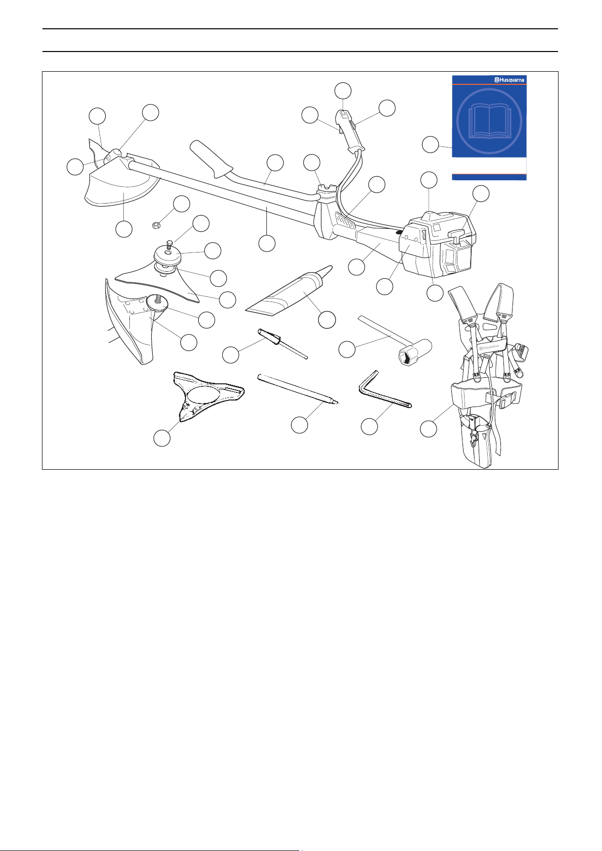
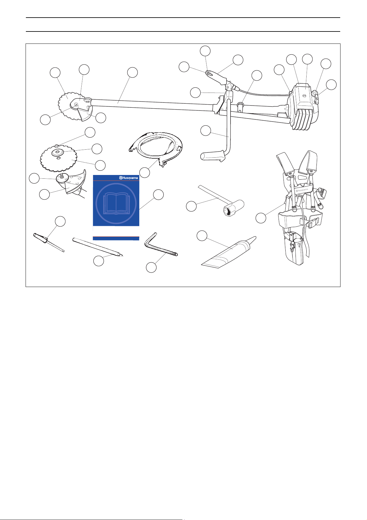
What is what on the clearing saw? (265RX)
1 Blade
2 Grease filler cap, bevel gear
3 Bevel gear
4 Cutting attachment guard
5 Shaft
6 Handlebar
7 Throttle control
8 Stop switch
9 Throttle lock
10 Support eyes for harness
11 Cylinder cover
12 Starter handle
13 Fuel tank
14 Choke control
15 Air filter
16 Handle adjustment
17 Locking nut
18 Support flange
19 Drive disc
20 Socket spanner
21 Operator’s manual
22 Transport guard
23 Allen key
24 Carburettor screwdriver
25 Locking pin
26 Harness
27 Gearbox grease
English
– 9
GENERAL SAFETY PRECAUTIONS
Important
IMPORTANT!
The machine is only designed for trimming grass, grass
clearing and/or forestry clearing.
The only accessories you can operate with this engine unit
are the cutting attachments we recommend in the chapter
on Technical data.
Never use the machine if you are tired, if you have drunk
alcohol, or if you are taking medication that could affect your
vision, your judgement or your co-ordination.
Wear personal protective equipment. See instructions
under the heading Personal protective equipment.
Never use a machine that has been modified in any way
from its original specification.
Never use a machine that is faulty. Carry out the checks,
maintenance and service instructions described in this
manual. Some maintenance and service measures must be
carried out by trained and qualified specialists. See
instructions under the heading Maintenance.
All covers and guards must be fitted before starting. Ensure
that the spark plug cap and ignition lead are undamaged to
avoid the risk of electric shock.
The machine operator must ensure that no people or
animals come closer than 15 metres while working. When
several operators are working in the same area the safety
distance should be at least twice the tree height and no less
than 15 metres.
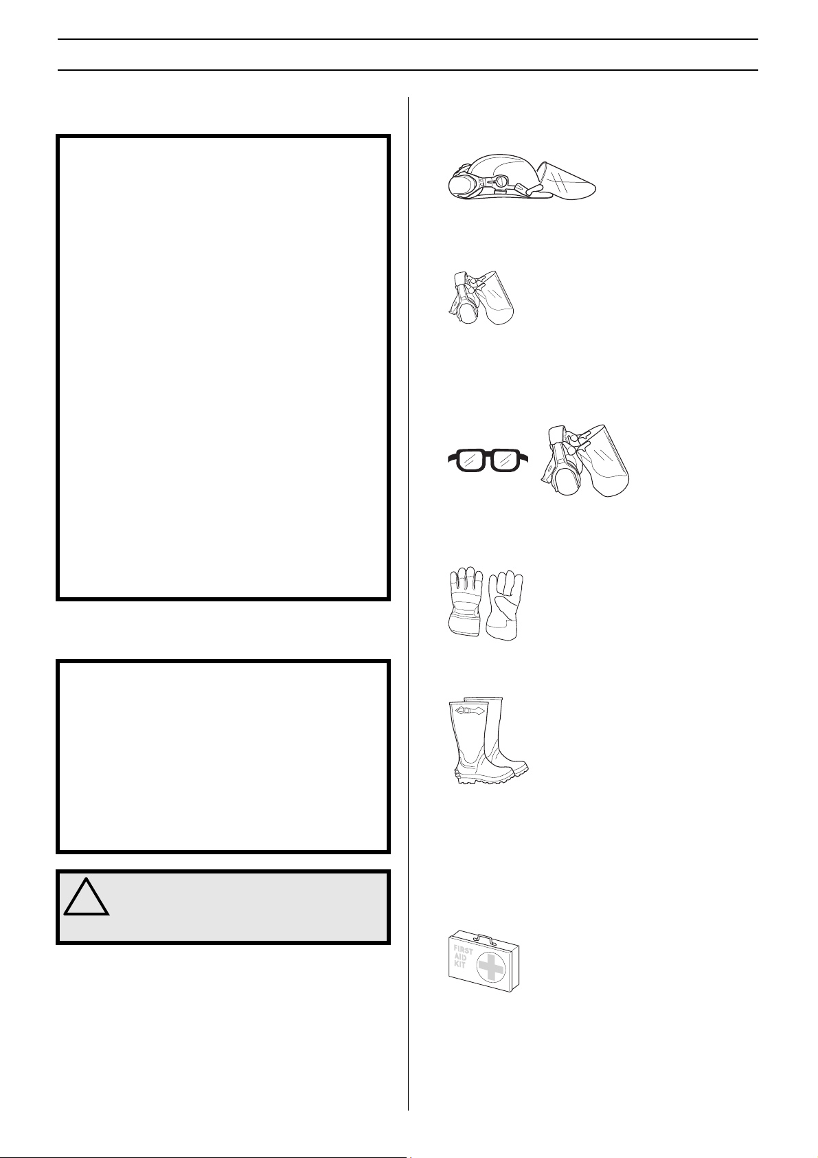
HELMET
A helmet should be worn if the trees being cleared are taller
than 2 m.
HEARING PROTECTION
Wear hearing protection that provides adequate noise
reduction.
EYE PROTECTION
Always wear approved eye protection. If you use a visor then
you must also wear approved protective goggles. Approved
protective goggles must comply with standard ANSI Z87.1 in
the USA or EN 166 in EU countries.
GLOVES
Gloves should be worn when necessary, e.g., when fitting
cutting attachments.
Personal protective equipment
IMPORTANT!
A clearing saw, brushcutter or trimmer can be dangerous if
used incorrectly or carelessly, and can cause serious or
fatal injury to the operator or others. It is extremely
important that you read and understand the contents of this
operator’s manual.
You must use approved personal protective equipment
whenever you use the machine. Personal protective
equipment cannot eliminate the risk of injury but it will
reduce the degree of injury if an accident does happen. Ask
your dealer for help in choosing the right equipment.
WARNING! Listen out for warning signals or
shouts when you are wearing hearing
!
protection. Always remove your hearing
protection as soon as the engine stops.
BOOTS
Wear sturdy, non-slip boots.
CLOTHING
Wear clothes made of a strong fabric and avoid loose clothing
that can catch on twigs and branches. Always wear heavy,
long pants. Do not wear jewellery, shorts sandals or go
barefoot. Secure hair so it is above shoulder level.
FIRST AID KIT
Always have a first aid kit nearby.
10 –
English
′
GENERAL SAFETY PRECAUTIONS
Machine ′′
This section describes the machine ′ s safety equipment, its
purpose, and how checks and maintenance should be carried
out to ensure that it operates correctly. See the ”What is
what?” section to locate where this equipment is positioned
on your machine.
The life span of the machine can be reduced and the risk of
accidents can increase if machine maintenance is not carried
out correctly and if service and/or repairs are not carried out
professionally. If you need further information please contact
your nearest servicing dealer.
IMPORTANT!
All servicing and repair work on the machine requires
special training. This is especially true of the machine
safety equipment. If your machine fails any of the checks
described below you must contact your service agent.
When you buy any of our products we guarantee the
availability of professional repairs and service. If the retailer
who sells your machine is not a servicing dealer, ask him for
the address of your nearest service agent.
!
′′
s safety equipment
s
WARNING! Never use a machine with faulty
safety equipment. The machine’s safety
equipment must be checked and maintained
as described in this section. If your machine
fails any of these checks contact your
service agent to get it repaired.
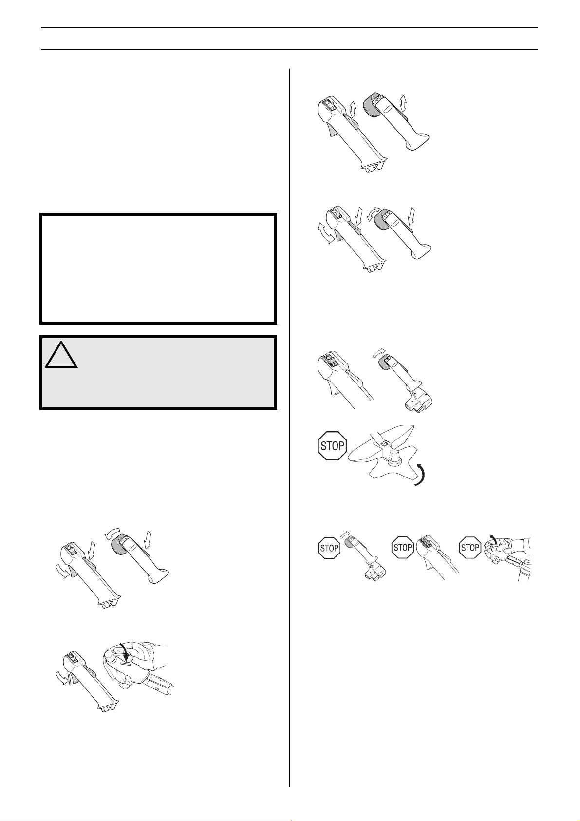
Press the throttle lock and make sure it returns to its original
position when you release it.
Check that the throttle control and throttle lock move freely
and that the return springs work properly.
See instructions under the heading Start. Start the machine
and apply full throttle. Release the throttle and check that the
cutting attachment stops and remains at a standstill. If the
cutting attachment rotates with the throttle in the idle position
then the carburettor idle setting must be checked. See
instructions under the heading Maintenance.
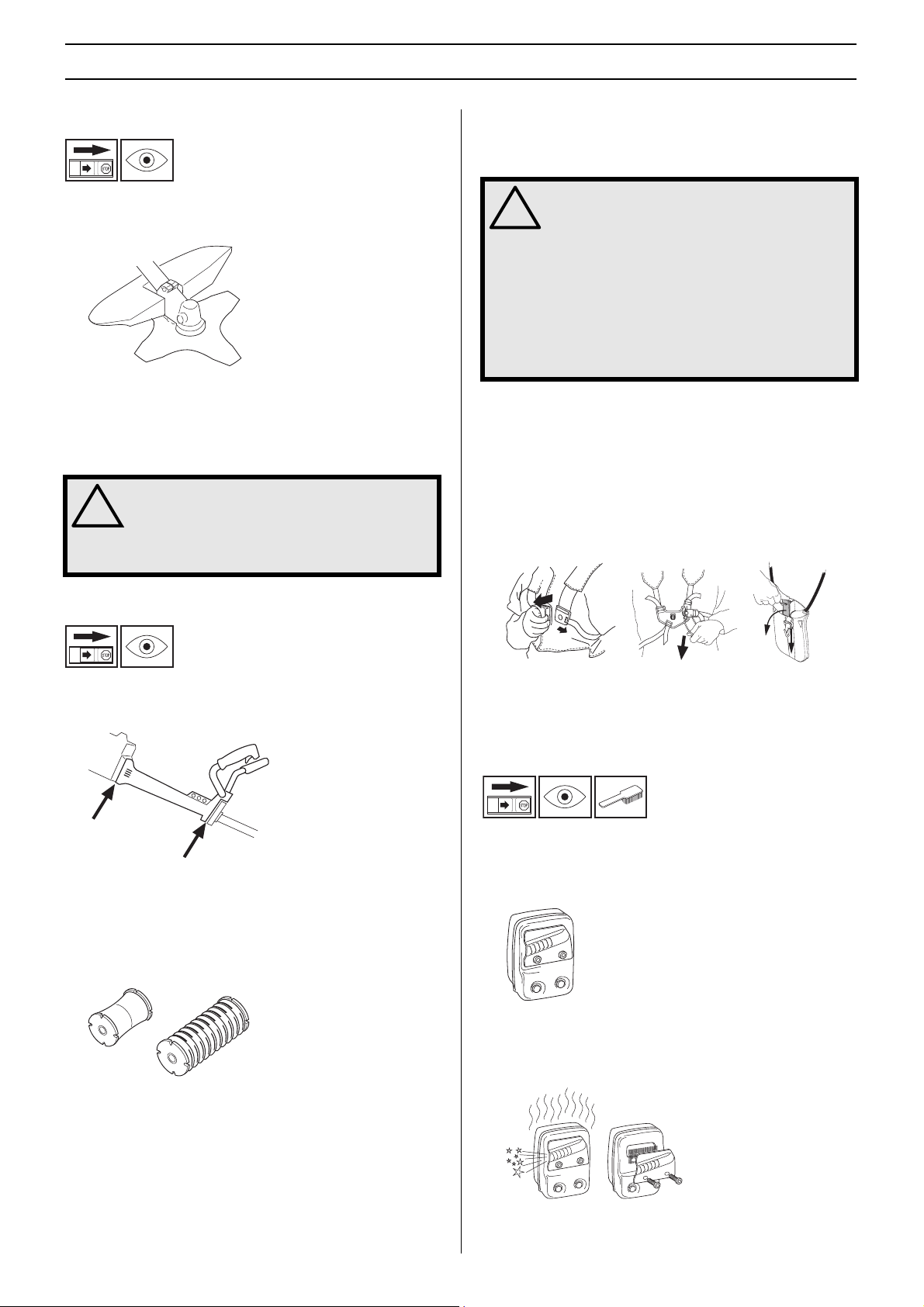
Throttle lock
The throttle lock is designed to prevent accidental operation
of the throttle control. When you press the lock (A) (i.e. when
you grasp the handle) it releases the throttle control (B).
When you release the handle the throttle control and the
throttle lock both move back to their original positions. This
movement is controlled by two independent return springs.
This arrangement means that the throttle control is
automatically locked at the idle setting.
B
A
B
Make sure the throttle control is locked at the idle setting
when the throttle lock is released.
A
Stop switch
Use the stop switch to switch off the engine.
Start the engine and make sure the engine stops when you
move the stop switch to the stop setting.
English
– 11
GENERAL SAFETY PRECAUTIONS
Cutting attachment guard
This guard is intended to prevent loose objects from being
thrown towards the operator. The guard also protects the
operator from accidental contact with the cutting attachment.
Check that the guard is undamaged and not cracked. Replace
the guard if it has been exposed to impact or is cracked.
Always use the recommended guard for the cutting
attachment you are using. See chapter on Technical data.
WARNING! Never use a cutting attachment
without an approved guard. See the chapter
!
on Technical data. If an incorrect or faulty
guard is fitted this can cause serious
personal injury.
Regularly check the vibration damping units for cracks or
deformation. Check that the vibration damping element is
undamaged and securely attached.
WARNING! Overexposure to vibration can
lead to circulatory damage or nerve damage
!
in people who have impaired circulation.
Contact your doctor if you experience
symptoms of overexposure to vibration.
Such symptoms include numbness, loss of
feeling, tingling, pricking, pain, loss of
strength, changes in skin colour or
condition. These symptoms normally appear
in the fingers, hands or wrists. The risk
increases at low temperatures.
Quick release
There is an easily accessible, quick release fitted at the front
as a safety precaution in case the engine catches fire, or in
any other situation that requires you to free yourself from the
machine and harness. See instructions under the heading
Adjusting the harness and clearing saw.
Certain harnesses also have a quick release fitted to the
support hook.
Vibration damping system
Your machine is equipped with a vibration damping system
that is designed to reduce vibration and make operation
easier.
Use of incorrectly wound cord or an incorrect cutting
attachment increases the level of vibration. See instructions
under the heading Cutting equipment.
The machine ′ s vibration damping system reduces the transfer
of vibration between the engine unit/cutting equipment and
the machine ′ s handle unit.
Check that the harness straps are correctly positioned. Once
the harness and machine have been adjusted, check that the
harness quick release works correctly.
Muffler
The muffler is designed to keep noise levels to a minimum
and to direct exhaust fumes away from the user.
A muffler fitted with a catalytic converter is also designed to
reduce harmful exhaust gases.
In countries that have a warm and dry climate there is a
significant risk of fire. We therefore fit certain mufflers with a
spark arrestor mesh. Check whether the muffler on your
machine is fitted with this kind of mesh.
12 –
English
GENERAL SAFETY PRECAUTIONS
For mufflers it is very important that you follow the instructions
on checking, maintaining and servicing your machine. See
instructions under the heading Checking, maintaining and
servicing the machine’s safety equipment.
Never use a machine that has a faulty muffler.
Regularly check that the muffler is securely attached to the
machine.
If the muffler on your machine is fitted with a spark arrestor
mesh this must be cleaned regularly. A blocked mesh will
cause the engine to overheat and may lead to serious
damage.
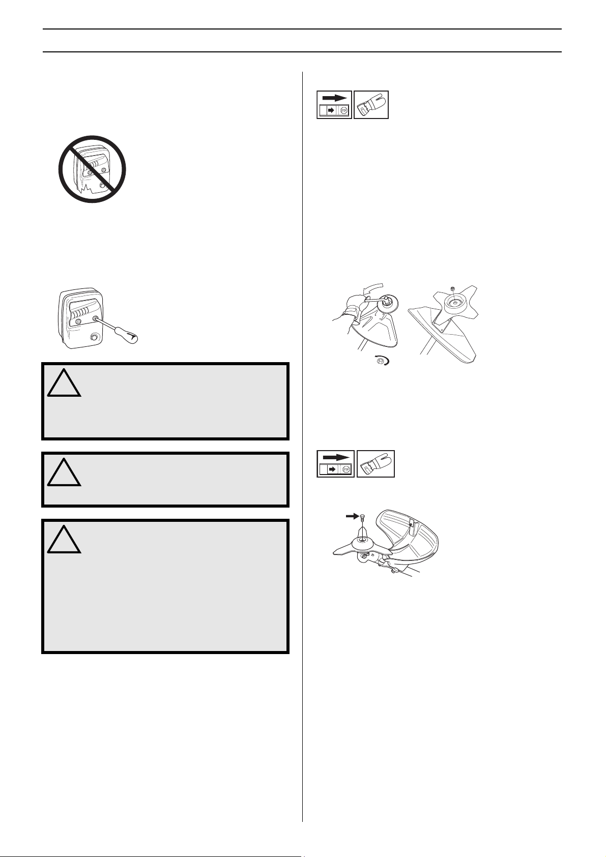
Locking nut
A locking nut is used to secure some types of cutting
attachment.
When fitting, tighten the nut in the opposite direction to the
direction of rotation of the cutting attachment. To remove it,
undo the nut in the same direction as the cutting attachment
rotates. (CAUTION! The nut has a left-hand thread.)
When loosening and tightening the saw blade nut, there is a
risk of injury from the teeth of the saw blade. You should
therefore always ensure that your hand is shielded by the
blade guard when doing this. Always use a socket spanner
with a shaft that is long enough to allow this. The arrow in the
diagram shows the area where you should operate the socket
spanner when loosening or tightening the nut.
WARNING! Mufflers fitted with catalytic
converters get very hot during use and
!
remain so for some time after stopping. This
also applies at idle speed. Contact can result
in burns to the skin. Remember the risk of
fire!
WARNING! The inside of the muffler contain
chemicals that may be carcinogenic. Avoid
!
contact with these elements in the event of a
damaged muffler.
WARNING! Bear in mind that:
Engine exhaust fumes contain carbon
!
monoxide, which can cause carbon
monoxide poisoning. For this reason you
should not start or run the machine indoors,
or anywhere that is poorly ventilated.
The exhaust fumes from the engine are hot
and may contain sparks which can start a
fire. Never start the machine indoors or near
combustible material!
The nylon lining inside the locking nut must not be so worn
that you can turn it by hand. The lining should offer a
resistance of at least 1.5 Nm. The nut should be replaced
after it has been put on approx. 10 times.
Locking screw
The lock screw must be tightened securely for ball-bearingmounted support cups.
English
– 13

GENERAL SAFETY PRECAUTIONS
Cutting equipment
This section describes how to choose and maintain your
cutting equipment in order to:
• Reduce the risk of blade thrust.
• Obtain maximum cutting performance.
• Extend the life of cutting equipment.
IMPORTANT!
Only use cutting attachments with the guards we
recommend! See the chapter on Technical data.
Refer to the instructions for the cutting attachment to check
the correct way to load the cord and the correct cord
diameter.
Keep the teeth of the blade correctly sharpened! Follow our
recommendations. Also refer to the instructions on the
blade packaging.
Maintain the correct blade setting! Follow our instructions
and use the recommended file gauge.
WARNING! Always stop the engine before
doing any work on the cutting attachment.
!
This continues to rotate even after the
throttle has been released. Ensure that the
cutting attachment has stopped completely
and disconnect the HT lead from the spark
plug before you start to work on it.
WARNING! Using an incorrect cutting
attachment or an incorrectly sharpened
!
blade increases the risk of kickback.
General rules
Only use cutting attachments with the guards we
recommend! See the chapter on Technical data.
Keep the teeth of the blade correctly sharpened! Follow our
instructions and use the recommended file gauge. An
incorrectly sharpened or damaged blade increases the risk of
accidents.
Keep the correct setting on the saw blade! Follow our
instructions and use the recommended setting tool. An
incorrectly set saw blade increases the risk of jamming and
kickback, and damage to the saw blade.
Check the cutting attachment for damage or cracks. A
damaged cutting attachment should always be replaced.
Cutting equipment
Saw blades are intended for cutting fibrous types of wood.
Grass blades and grass cutters are intended for cutting
coarse grass.
A trimmer head is intended for trimming grass.
14 –
English

GENERAL SAFETY PRECAUTIONS
Sharpening grass cutters and grass blades
• See the cutting attachment packaging for correct
sharpening instructions. Sharpen blades and cutters
using a single-cut flat file.
• Sharpen all edges equally to maintain the balance of the
blade.
WARNING! Always discard a blade that is
bent, twisted, cracked, broken or damaged
!
in any other way. Never attempt to straighten
a twisted blade so that it can be reused. Only
use original blades of the specified type.
Sharpening the saw blade
Adjust the blade setting. This should be 1 mm.
Trimmer head
IMPORTANT!
Always ensure the trimmer cord is wound tightly and evenly
around the drum, otherwise the machine will generate
harmful vibration.
• Only use the recommended trimmer heads and trimmer
cords. These have been tested by the manufacturer to suit
a particular engine size. This is especially important when
a fully automatic trimmer head is used. Only use the
recommended cutting attachment. See the chapter on
Technical data.
• See the cutting attachment packaging for correct
sharpening instructions.
A correctly sharpened blade is essential for working efficiently
and to avoid unnecessary wear to the blade and clearing saw.
• Make sure that the blade is well supported when you file
it. Use a 5.5 mm round file with a file holder.
• The filing angle is 15 ° . File alternate teeth to the right and
those in between to the left. If the blade has been heavily
pitted by stones it may be necessary to dress the top
edges of the teeth with a flat file, in exceptional cases. If
so, this should be done before filing with a round file. The
top edges must be filed down by the same amount for all
the teeth.
• Smaller machines generally require small trimmer heads
and vice versa. This is because when clearing using a
cord the engine must throw out the cord radially from the
trimmer head and overcome the resistance of the grass
being cleared.
• The length of the cord is also important. A longer cord
requires greater engine power than a shorter cord of the
same diameter.
• Make sure that the cutter on the trimmer guard is intact.
This is used to cut the cord to the correct length.
• To increase the life of the cord it can be soaked in water
for a couple of days. This will make the line tougher so that
it lasts longer.
English
– 15
 Loading...