

Instruction Manual
136LE / 141LE
Read and follow all Safety Rules and Operating
Instructions before using this product. Failureto
do so can result in serious injury.
136 / 141
530163874 6/18/03
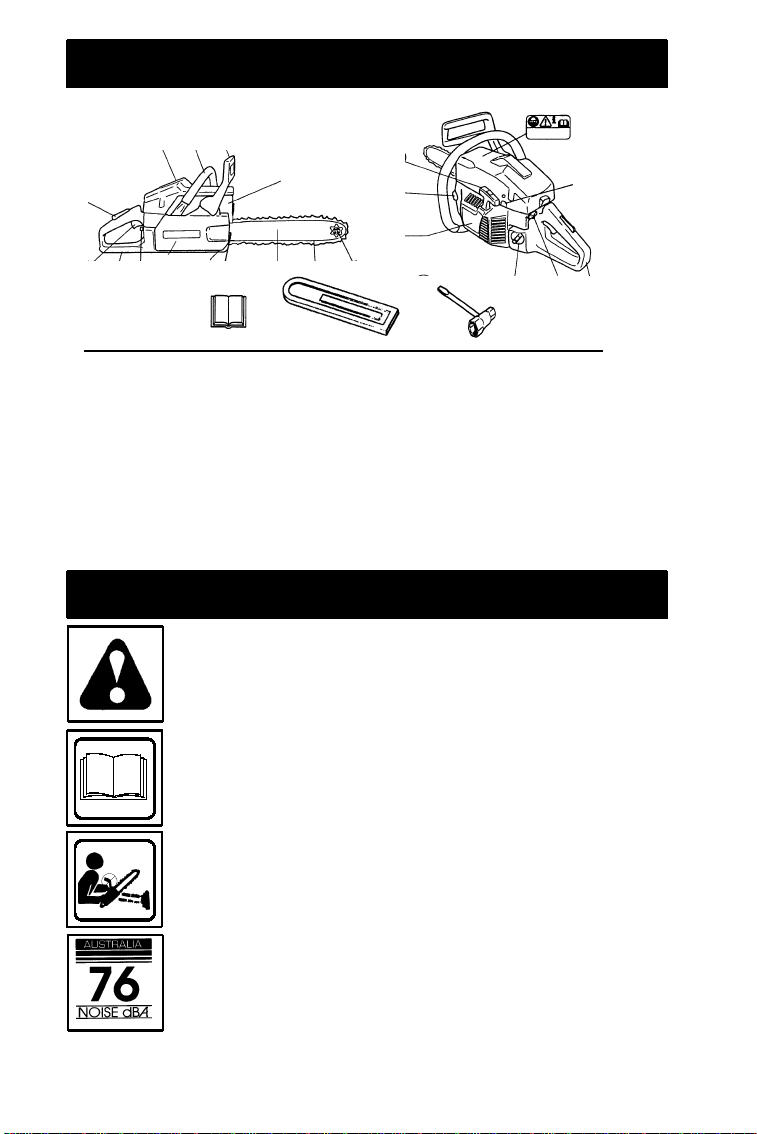
IDENTIFICATION (WHAT IS WHAT?)
321
20
19
18
1. Cylinder Cover
2. Front Handle
3. Front Hand Guard
4. Starter Cover
5. Chain Oil Tank
6. Starter Handle
7. Carburetor AdjustingScrew
8. Choke Control
9. Rear Handle
10. ON/OFF Stop Switch
11. Fuel Tank
12. Muffler
1617
8
22
IDENTIFICATION OF SYMBOLS
WARNING!
use can cause serious or even fatal injury.
21
1
7
10
9
11
6
12
1415
This chain saw can be dangerous! Careless or improper
5
4
13
2423
13. Bar Tip Sprocket
14. Saw Chain
15. Saw Bar
16. Chain Catcher
17. Chain Brake Assembly
18. Rear Hand Guard
19. Throttle Control/Trigger
20. Throttle Lock
21. Bar/Chain Adjustment Tool
22. Chain Tensioning Screw
23. Instruction Manual
24. Guide Bar Cover
Read and understand the instruction manual before using the chain saw.
XX_
Measuredmaximumkickbackvalue without chainbrakefor the bar and
chain combination on the label.
Sound pressure level at 15 meters (50 feet)
There may be more symbols found on your unit other than those listed above. These
symbols may represent compliances, standards, or other matters concerning the product.
2
SAFETY RULES
WARNING:
spark plugwire and place wire where it cannotcontact spark plugto prevent accidental
starting when setting up, transporting,adjusting or making repairs except carburetor
adjustments.
Becausea chain saw is a high-speedwoodcutting tool, special safety precautionsmust
beobserved to reduce the risk of accidents.
Careless or improper use of this tool can
cause serious injury.
PLAN AHEAD
S Readthis manual carefully until you com-
pletely understandand canfollow all safety rules, precautions, and operating instructions before attempting to use the
unit.
S Restricttheuse of yoursawto adult users
who understand and can follow safety
rules, precautions,and operating instructions found in thismanual.
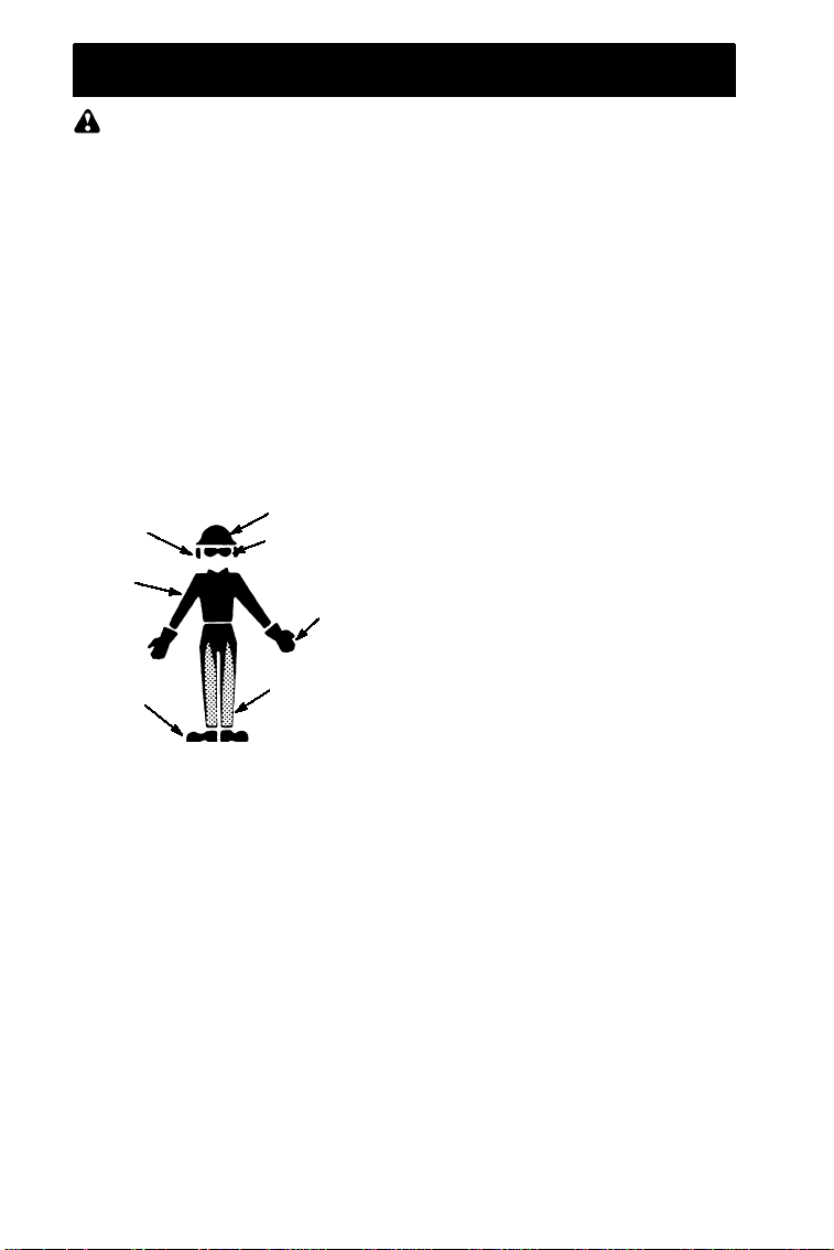
Hearing
Protection
Snug
Fitting
Clothing
Safety
Shoes
S Wear protective gear. Always use steel-
toed safety footwear with non-slip soles;
snug-fitting clothing; heavy-duty, non-slip
gloves; eye protection such as non-fogging, vented goggles or face screen; an
approvedsafetyhardhat;and soundbarriers (ear plugs or mufflers) to protect your
hearing. Regular users shouldhavehearing checked regularly as chain saw noise
can damage hearing. Secure hair above
shoulder length.
S Keep all parts of your body away from the
chain when the engine is running.
S Keep children, bystanders,andanimals a
minimum of 30 feet (10 meters)awayfrom
the workarea. Do not allow other people
or animalsto be near the chain saw when
starting or operating the chain saw.
S Do not handle or operate a chain saw
whenyouarefatigued,ill,orupset,or if you
have taken alcohol,drugs, or medication.
You must be in good physical condition
and mentally alert. Chain saw work is
strenuous. If you have any condition that
might be aggravated by strenuous work,
check with your doctor before operatinga
chain saw.
Always disconnect
Safety Hat
Eye
Protection
Heavy Duty
Gloves
Safety Chaps
S Carefullyplanyoursawingoperationinad-
vance. Donotstartcuttinguntilyouhavea
clearwork area, secure footing, and, if you
are felling trees,a planned retreat path.
OPERATE YOUR SAW SAFELY
S Donotoperateachainsawwith one hand.
Serious injury to the operator, helpers,bystanders or any combinationof these persons may result from one-handed operation. A chain saw is intended for
two-handed use.
S Operatethechainsaw only inawell-venti-
lated outdoorarea.
S Do not operate saw from a ladder or in a
tree.
S Makesurethechain will notmake contact
with any object while starting the engine.
Never try to startthe saw when the guide
bar is in a cut.
S Do not put pressure onthe saw at the end
of the cut. Applying pressure can cause
you to lose control when the cut is completed.
S Stop the engine before setting the saw
down.
S Do not operate a chain saw that is dam-
aged, improperly adjusted, or not completely and securely assembled. Always
replace bar, chain, hand guard, or chain
brakeimmediately ifit becomesdamaged,
broken or is otherwise removed.
S With the engine stopped, hand carry the
chain saw with the muffleraway from your
body, and the guide bar and chain to the
rear,preferably covered with a scabbard.
MAINT AINYOUR SAW IN GOOD
WORKINGORDER
S Haveall chain saw service performedby a
qualified servicedealer with the exception
ofthe items listed inthe maintenancesectionofthismanual. Forexample,ifimpropertools areusedtoremoveor hold theflywheelwhenservicingtheclutch,structural
damage to the flywheel can occur and
cause the flywheel to burst.
S Make certain the saw chain stops moving
when the throttle trigger is released. For
correction, refer to CARBURETOR ADJUSTMENTS.
S Never modify your saw in any way.
S Keepthehandlesdry,clean,andfreeofoil
or fuel mixture.
S Keep fuel and oil caps, screws, and fas-
teners securely tightened.
S Use only Husqvarna accessories and re-
placement parts as recommended.
HANDLE FUEL WITH CAUTION
S Do not smoke while handling fuel or while
operating the saw.
S Eliminate all sources ofsparks or flame in
the areas where fuel is mixed or poured.
Thereshouldbenosmoking,openflames,
orworkthatcouldcausesparks. Allowengine to cool beforerefueling.
S Mix and pour fuel in an outdoor area on
bare ground; store fuel in a cool, dry, well
3
ventilated place; and use an approved,
marked container for all fuel purposes.
Wipe up all fuel spills beforestartingsaw.
S Moveat least 10 feet (3meters) from fuel-
ing site before startingengine.
S Turn the engine off and let saw cool in a
non-combustible area, not on dry leaves,
straw,paper,etc. Slowly remove fuel cap
and refuel unit.
S Storetheunitandfuelinanareawherefuel
vapors cannot reach sparks or open
flames from waterheaters,electric motors
or switches, furnaces, etc.
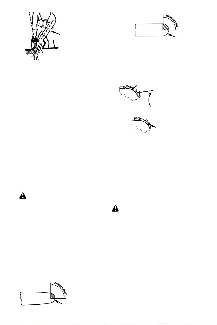
KICKBACK
WARNING:
can resultin seriousinjury. Kickbackisthe
backward,upwardorsudden forwardmotion
of the guide bar occurring when the saw
chainneartheuppertip of theguidebarcontacts any object such as a log or branch, or
when the wood closes in and pinches the
sawchain in thecut.Contactingaforeignobject in the wood can also result in loss of
chain saw control.
S RotationalKickbackcanoccurwhenthe
moving chain contacts an objectattheupper tip of the guide bar. This contact can
cause the chain to dig into the object,
which stops the chain for an instant. The
result is a lightning fast, reversereaction
which kicks the guide bar up and back toward the operator.
S Pinch-Kickbackcan occur when the the
wood closes in and pinches the moving
saw chain in the cut along the top of the
guide bar and the saw chain is suddenly
stopped. This sudden stopping of the
chain results in a reversal of the chain
force used to cut wood and causes the
sawtomoveintheopposite direction of the
chain rotation. The saw is driven straight
back toward theoperator.
S Pull-Incan occurwhen the moving chain
contactsaforeignobject in thewoodinthe
cut along the bottom of the guide bar and
the saw chain is suddenly stopped. This
suddenstoppingpullsthesawforwardand
away from the operator and could easily
cause the operator to lose control of the
saw.
Avoid Pinch--Kickback:
S Be extremely aware of situations or ob-
structions that can causematerial topinch
the top of or otherwise stop the chain.
S Donot cut morethan one log at a time.
S Do not twist the saw as the bar is with-
drawn from an undercut when bucking.
AvoidPull--In:
S Alwaysbegincutting withtheengineatfull
speedandthe saw housingagainst wood.
S Use wedges made of plastic or wood.
Never use metal to holdthe cut open.
Avoid kickback which
Kickback Path
Avoid Obstructions
Clear The Working Area
REDUCETHE CHANCE OF
KICKBACK
S Recognize that kickback can happen.
With a basic understanding of kickback,
you can reduce the element of surprise
which contributes to accidents.
S Neverletthemovingchaincontactanyob-
ject at the tipof the guide bar.
S Keep the working area free from obstruc-
tionssuchasoth ertrees,branches,rocks,
fences, stumps, etc. Eliminate or avoid
any obstructionthatyour sawchain could
hit while you are cutting. When cutting a
branch, do not let the guide bar contact
branch or other objects around it.
S Keep your saw chain sharp and properly
tensioned. A loose or dull chain can increase the chanceof kickback occurring.
Follow manufacturer’s chain sharpening
andmaintenanceinstructions. Check tension at regular intervals with the engine
stopped, never with the engine running.
Makesurethebarclamp nutsaresecurely
tightened after tensioning the chain.
S Beginandcontinue cutting atfull speed. If
the chain is moving at a slower speed,
thereis greaterchanceofkickback occurring.
S Cutone log at a time.
S Use extreme caution when re-entering a
previous cut.
S Do not attempt cuts startingwith the tip of
the bar (plunge cuts).
S Watch for shifting logs or other forces that
could close a cut and pinch or fall into
chain.
S Use the Reduced--Kickback Guide Bar
and Low--Kickback Chain specified for
your saw.
MAINTAINCONTROL
Stand to the left of
the saw
Never reverse
hand positions
4
Symmetrical Guide Bar
Elbow locked
Thumb on underside of
handlebar
S Keep a good,firm gripon thesawwithboth
hands when the engine is running and
don’tlet go. Afirmgrip will helpyoureduce
kickback and maintain control of the saw.
Keep the fingers of your left hand encircling and your left thumb under the front
handlebar. Keep your right hand completely around the rear handle whether
yourarerighthandedorlefthanded. Keep
your left arm straight with the elbow
locked.
S Positionyourleft hand onthe front handle-
bar so it is in a straight line with your right
hand on the rear handle when making
bucking cuts. Never reverserightandleft
hand positionsfor any type of cutting.
S Stand withyourweightevenly balancedon
both feet.
S Stand slightly to the left side of the saw to
keep your body from being in a direct line
with the cuttingchain.
S Donotoverreach. Youcould be drawnor
thrown off balance and losecontrol of the
saw.
S Donotcut aboveshoulderheight. Itisdiffi-
cult to maintain control of saw above
shoulder height.
KICKBACKSAFETY FEATURES
WARNING:
are included on your saw to helpreduce the
hazard of kickback; however,such features
will not totally eliminate this dangerousreaction. As achainsaw user,donotrely onlyon
safety devices. You must follow all safety
precautions, instructions, and maintenance
in this manual to help avoid kickback and
other forces which can result in serious
injury.
S Reduced--Kickback Guide Bar, designed
with a small radius tip which reduces the
size of the kickback danger zone on the
bar tip. A Reduced--Kickback Guide Bar
has been demonstrated to significantlyreducethe number and seriousnessof kickbacks when tested in accordance with
safety requirementsfor gasolinepowered
chain saws as set by ANSI B175.1.
Reduced Kickback Symmetrica l Guide Bar
The following features
Small Radius Tip
S Low--Kickback Chain, designed with a
contoured depth gauge and guard link
which deflect kickback force and allow
wood to gradually ride into the cutter.
Low--Kickback Chain has met kickback
performance requirements when tested
on a representative sampleof chain saws
below 3.8 cubic inch displacement specified in ANSI B175.1.
Low---Kickback
Chain
Not a Low ---Kickback Chain
S FrontHandGuard,designedtoreducethe
chance of your left hand contacting the
chainif your handslips offthefronthandlebar.
S Position of front and rear handlebars, de-
signedwithdistancebetweenhandlesand
“in-line” with each other. The spread and
“in-line” position of the hands provided by
this design work together to give balance
and resistance in controlling the pivot of
the saw back toward the operator if kickback occurs.
CHAIN BRAKE AND CKA ANGLE
S ChainBrake, designed to stop thechainin
the event of kickback.
WARNING:
RESENT AND YOU SHOULD NOT ASSUME THAT THE CHAIN BRAKE WILL
PROTECT YOU IN THE EVENT OF A
KICKBACK. Kickback is a lightning fastaction which throws the bar and rotating chain
back and up toward the operator. Kickback
can be caused byallowing contactofthebar
tip in the danger zone with any hard object.
Kickback canalsobecausedbypinchingthe
sawchainalongthetopoftheguidebar. This
action may push the guidebar rapidly back
toward the operator. Either of these events
may cause you to lose control of the saw
which could result in serious injury or even
death. DONOT RELYUPONANY OF THE
DEVICES BUILT INTO YOUR SAW. YOU
SHOULDUSETHESAW PROPERLYAND
CAREFULLY TO AVOID KICKBACK. Reduced--kickback guide bars and low--kickback saw chains reduce the chance and
magnitude of kickback and are recommended. Yoursawhasalowkickback chain
andbaras originalequipment. Repairs on a
Contoured Depth Gauge
Large Radius Tip
Elongated Guard Link
Deflects
kickback force
and allows wood
to gradually ride
into cutter
Can Obstruct Material
WE DO NOT REP-
5

chain brake should be made by an authorized servicing dealer. Take your unit to the
place of purchase if purchased from a
Husqvarna servicing dealer, or to the near-
est authorized Husqvarna service dealer.
S Tip contact in some cases may cause a
lightning fast reverse REACTION, kicking
theguidebarupandbacktowardtheoperator.
S Pinchingthesawchainalongthetopofthe
guide bar may push the guide bar rapidly
back toward theoperator.
S Eitherofthesereactionsmaycauseyouto
lose control of the sawwhich couldresult
in serious injury. Do not rely exclusively
uponthesafety devicesbuiltintoyoursaw.
WARNING:
angle (CKA) listed on your saw and listed in
the CKA table below represents angle of
kickback your bar and chain combinations
will have when tested in accordance with
CSA(CanadianStandardsAssociation) and
Computed kickback
Computedkickback angle (CKA) Table
BAR
MODEL
136
136
141
141 0.050 GA 18
NOTE:
commercial logging, a chain brake is
required and shall not be removed or
otherwise disabled to comply with Federal
OSHARegulationsforCommercialLogging.
Contact your authorized Husqvarnaservice
dealer.
SAFETY NOTICE:
vibrations throughprolongeduseofgasoline
powered hand tools could cause blood
vessel or nerve damage in the fingers,
hands, and joints of people prone to
circulation disordersor abnormal swellings.
Prolonged use in cold weather has been
linked to blood vessel damage in otherwise
healthy people. If symptoms occur such as
numbness, pain, loss of strength, changein
skin color or texture, or loss of feeling in the
fingers,hands, or joints, discontinuetheuse
of this tool and seek medical attention. An
anti-vibrationsystemdoesnotguaranteethe
avoidance of these problems. Users who
operate power tools on a continual and
regular basis must monitor closely their
physical condition and the condition of this
tool.
SPECIALNOTICE:
with a temperaturelimitingmuffler andspark
arresting screen which meets the
requirements of CaliforniaCodes 4442 and
If this saw is to be used for
Type Length CHAIN TYPE
0.050 GA 14!91VG/VJ--- 52
0.050 GA
0.050 GA
Exposure to
Y oursaw isequipped
16
16
!
!
!
ANSI standards.Whenpurchasing replacement bar and chain, considerations should
be given to the lower CKA values. Lower
CKA values represent safer angles to the
user,higher values indicate moreangle and
higher kick energies.Computedangles represented in the non-activated column indicatetotal energy andangle associated without activation of the chain brake during
kickback. Activated angle representschain
stopping time relative to activation angle of
chain breakandresulting kick angle of saw.
In all cases lower CKA values representa
safer operating environmentfor the user.
The followingguide bar and chain combinations meet kickback requirements of CSA
Standards Z62.1, Z62.3, & ANSI B175.1
when used on saws listed in this manual.
Use of bar and chain combinations other
than those listed is not recommended and
may not meet the CKA requirements per
standard.
CKA WITHOUT
CHAIN BRAKE
25_
_
91VG ---56
91VG ---56
H 3 0 --- 7 2
4443. All U.S. forest land and the states of
California, Idaho, Maine, Minnesota, New
Jersey, Oregon, and Washington require
many internal combustion engines to be
equipped with a spark arrestor screen by
law. If you operate a chain saw in a state or
locale wheresuch regulations exist, you are
legally responsible for maintaining the
operatingconditionofthese parts. Failureto
do so is a violation of the law. Refer to the
SERVICEANDADJUSTMENTS section for
maintenanceof theSparkArresting Screen.
Failure to follow all Safety Rules and
Precautions can result in serious injury. If
situationsoccurwhicharenotcoveredinthis
manual,usecareandgoodjudgement.Ifyou
need assistance, contact your authorized
service dealer.
STANDARDS
CSA Z62.1 “Chain Saws -- Occupational
Health and Safety”
CSA Z62.3 “Chain Saw Kickback Occupational Health and Safety”
ANSI B175.1--2000 -- “American National
Standard for Powered Tools -- Gasoline
Powered Chain Saw -- Safety Requirements”
25
25
38_
_
6

ASSEMBLY
p
Protective gloves (not provided) should be
wornduring assembly.
ATTACHINGTHE BAR & CHAIN
not alreadyattached)
WARNING:
blystepif the saw is receivedassembled.Always wear gloveswhen handlingthe chain.
The chain is sharp and can cut you even
when it is not moving!
1. Loosen and remove the clamp nuts and
the bar clamp fromthe saw.
2. Remove the plastic shipping spacer (if
present).
Bar Clamp/
Chain Brake
3. Anadjustingpinandscrew is usedtoadjust the tensionofthechain. It is very important when assembling the bar, that
the pin located on the adjusting screw
aligns into a hole in the bar. Turning the
screw will move the adjustment pin up
anddown the screw. Locate thisadjustment before you beginmounting the bar
ontothe saw. Seeillustration.
Adjustmentlocatedon Bar Clamp
4. Turn the adjusting screw counterclockwise to move the adjusting pin almostas
farasit will gototherear.This should allow the pin to be near the correct position. Furtheradjustment may be necessary as you mount the bar.
5. Slide guide bar behind clutch drum until
guide bar stops against clutch drum
sprocket.
Recheck each assem-
Location of shipping spacer
Bar Clamp Nuts
Mount the Bar
Bar Tool
Inside view of
Chain Brake
6. Prepare the chain by checking the proper
direction.With outfollo w ingtheillustratio nit
(If
is easytoplace the chainonthe saw in the
wron gdir ection. Use the illustratio n of the
chain to determinethe proper direction.
Tip of
Bar
CUTTERS MUST FACE IN
DIIRECTION OF ROTATION
Cutters
7. Place chain over and behind clutch, fitting the drive links in the clutch drum
sprocket.
Place chain onto thes
8. Fit bottom of drive links between the
teeth in the sprocket in the nose of the
guide bar.
9. Fit chain drive links into bar groove.
10. Pull guide bar forwarduntil chainis snug
in guide bar groove. Ensure all drive
links arein the bar groove.
11 Now,installchainbrakemakingsurethe
adjusting pin is positioned in the lower
hole in the guidebar. Remember this pin
moves the bar forwardand backwardas
the screwis turned.
12. Installchainbrakenuts and fingertighten
only. Once the chain is tensioned, you
will need to tighten chain brake nuts.
Drive Links
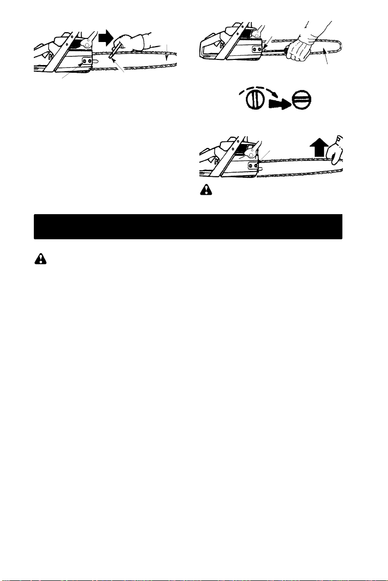
CHAIN TENSION
chain already installed)
: When adjusting chain tension,
NOTE
make sure the bar nuts are finger tight only.
Attemptingtotensionthechain when the bar
nuts are tight can cause damage.
Checking the tension:
Use the screwdriver end of the combination
screwdriver/wrench tool to move the chain
aroundthebar.Ifthechain does not rotate, it
istootight.Iftoo loose, the chain will sagbelow the bar.
Depth Gauge
rocket
(Includingunitswith
7
Guide
Bar
Adjusting
Screw
Chain Brake Nuts
Adjustingthe tension:
Chain tension is very important. Chain
stretches during use.This is especially true
during thefirst few times you use your saw.
Always check chain tension each time you
use and refuel your saw.
Y oucan adjust the chain tensionby loosening
the bar clamp nuts and turning the adjusting
screw 1/4 of a tu rn while lifting up on the bar.
S If chain is too tight, turn adjusting
screw 1/4 turn counterclockwise.
S If chain is too loose, turn adjusting
screw 1/4 turn clockwise.
Chain Adjustment
Tool (BarTool)
FUELING & LUBRICATION
FUELING ENGINE
WARNING:
when refueling.
This engine is certified to operate on
unleaded gasoline. Before operation,
gasoline must be mixed witha good quality
synthetic 2-cycle air-cooled engine oil
designed to be mixed at a ratio of 40:1. A
40:1ratioisobtainedbymixing3.2ouncesof
oil with 1 gallon of unleadedgasoline. DO
NOT USE automotive oil or boat oil. These
oilswill causeenginedamage.When mixing
fuel, follow instructionsprinted on container.
Once oil is added to gasoline, shake
containermomentarily to assure that the fuel
is thoroughly mixed. Always read and follow
thesafety rules relating to fuel beforefueling
your unit.
BAR AND CHAIN LUBRICATION
The bar and chain require continuous lubrication. Lubrication is provided by the automatic oiler system when the oil tank is kept
filled.Lack ofoil will quickly ruin the barand
chain. Too little oil will cause overheating
shownbysmoke coming from the chainand/
or discoloration of the bar.
Removefuel cap slowly
Chain Brake Nuts
Adjusting Screw -- 1/4 Turn
S Lift up the tip of the bar and tighten the
chain brake nuts withthe bar tool.
S Recheck chain tension.
WARNING:
with a loose chain, the chain could jump off
the guide bar and result in serious injury.
Infreezingweatheroil will thicken, making it
necessary to thin bar and chain oil with a
small amount(5 to 10%) of#1 Diesel Fuel or
kerosene. Bar and chain oil must be free
flowing for the oil system to pump enough oil
for adequate lubrication.
Genu ine Husqvarna bar and chain oil is recommended to protect yo urunit against excessive wearfrom heat andfriction. Husqvarnaoil
resists high tempera tu rethinning.
IfHusqvarnabaroil isnotavailable, use agood
grade SAE 30 oil.
S Never use waste oil for bar and chain lu-
brication.
S Always stop the engine before removing
the oil cap.
IMPORTANT
Experience indicates that alcohol--blended
fuels (called gasohol or using ethanol or
methanol) can attract moisturewhich leads
to separation and formationof acids during
storage. Acidic gas can damage the fuel
system of an engine while in storage. To
avoid engine problems, the fuel system
should be emptied before storage for 30
days or longer. Drainthegas tank,start the
engine and let it run until the fuel lines and
carburetor are empty. Use fresh fuel next
season. See STORAGE section for additional information.
Chain Brake
Nuts
If the saw is operated
Guide Bar
8
OPERATING YOUR UNIT
WARNING:
whenthe engine runs at idlespeed.Ifthe chain
moves at idle speed refer to CARBURETOR
ADJUS TMENTwithinthismanual.Avoidcontact with the muffler. A hot muffler can cause
serious burns.
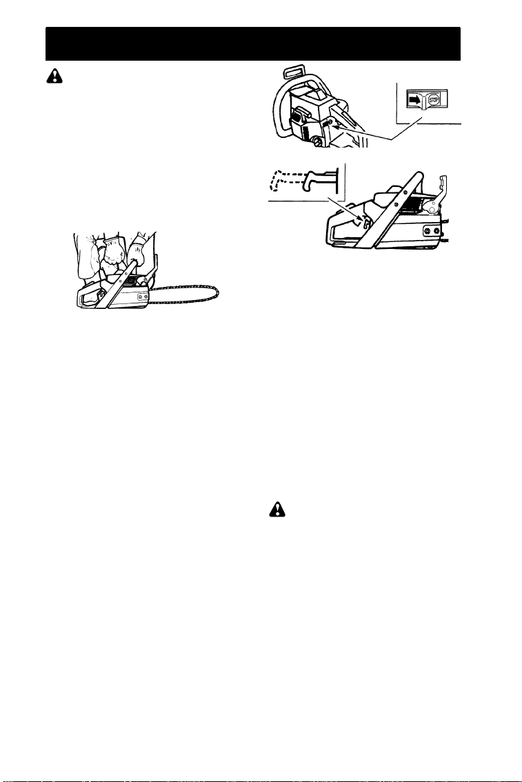
Tostop the engine move the switch to the
STOP position.
To start the engine hold the saw firmly on
the ground as illustrated below. Make sure
the chain is free to turn without contacting
any object.
Use only 15”--18” of rope per pull.
Hold saw firmly while pulling starter rope.
Importantpoints to remember
Whenpullingthestar terro pe,d onotuseth efull
extentof the rope asthis can causethe ropeto
break. Donot let starter rope snap back. Hold
the handle and let the ro pe rewind slowly.
Forcold weatherstarting,starttheunit at full
choke; allow the engine to warm up before
squeezing the throttletrigger.
Do not cut materialwith the choke/
NOTE:
fast idle lever at the FULL CHOKEposition.
The chain must notmove
STARTING A COLD ENGINE (or a
warm engine after running out of
fuel)
: In the following steps,when the cho-
NOTE
ke/fast idle lever is pulled out to the full exte nt,
the correct throttle settingfor starting is set automa tically.
1. MoveON/STOPswitch to the ONposition.
2. Pullthechoke/fastidleleverouttothefull
extent.
3. Pull starter rope quickly with your right
handamaximum of 10times. Then, proceed to the next step.
If theengine sounds as ifit is trying
NOTE:
tostart before the 10th pull, stop pulling and
immediately proceed to the next step.
4. Push the choke/fast idle lever in completely (to the OFF CHOKEposition).
5. Pull the starter rope quickly with your
right hand until the engine starts.
6. Allow the enginetorunforapproximately
5 seconds. Then,squeeze and release
throttletriggertoallowengineto returnto
idle speed.
ON/STOP SWITCH
CHOKE/FAST IDLE LEVER
FULL OFF
STARTING A WARM ENGINE
1. MoveON/STOPswitch to the ONposition.
2. Pullthechoke/fastidleleverouttothefull
extent; then, push the choke/fast idle
lever in completely (to the OFF CHOKE
position).
3. Pull the starter rope quickly with your
right hand until the engine starts.
4. Squeeze and release throttle trigger to
allow engine to return to idle speed.
DIFFICULT STARTING (or starting a
flooded engine)
The engine may be flooded with too much
fuel if it has not startedafter 10 pulls.
Flooded engines can be cleared of excess
fuel by following the warm engine starting
procedure listed above. Insure the ON/
STOPswitch is in the ON position.
Startingcouldrequire pulling the starterrope
handle many times dependingon how badly
theunitis flooded. Ifenginefails to startrefer
to the TROUBLESHOOTINGTABLE.
CHAIN BRAKE
WARNING:
too thin it may break when the chain brake is
triggered. Witha broken brake band, the chain
brake will not stopthe chain. The chain brake
should be replaced by an authorized service
dealer if any part is worn to less than 0.020!
(0.5 mm) thick. Repairs on a chain brake
should be madeby an authorizedservice dealer. Take your unit to the place of purchase if
purchased from a servicing dealer, or to the
nearest authorizedHusq varnaSer v iceD ealer.
S This saw is equipped with a chain brake.
The brakeis designed to stop the chain if
kickback occurs.
S The inertia--activated chain brake is
activated if the front handguardis pushed
forward, either manually (by hand) or
automatically (by sudden movement).
S If the brake is already activated, it is
disengagedbypullingthefronthandguard
back toward the front handle as far as
possible.
If the brake band is worn
9
S Whencuttingwiththesaw,thechainbrake
must be disengaged.
Disengaged
Engaged
Braking functioncontrol
CAUTION:
checked several times daily. The engine
mustberunningwhenperformingthisprocedure. This istheonlyinstance when the saw
should be placed on the ground with the engine running.
The chain brake must be
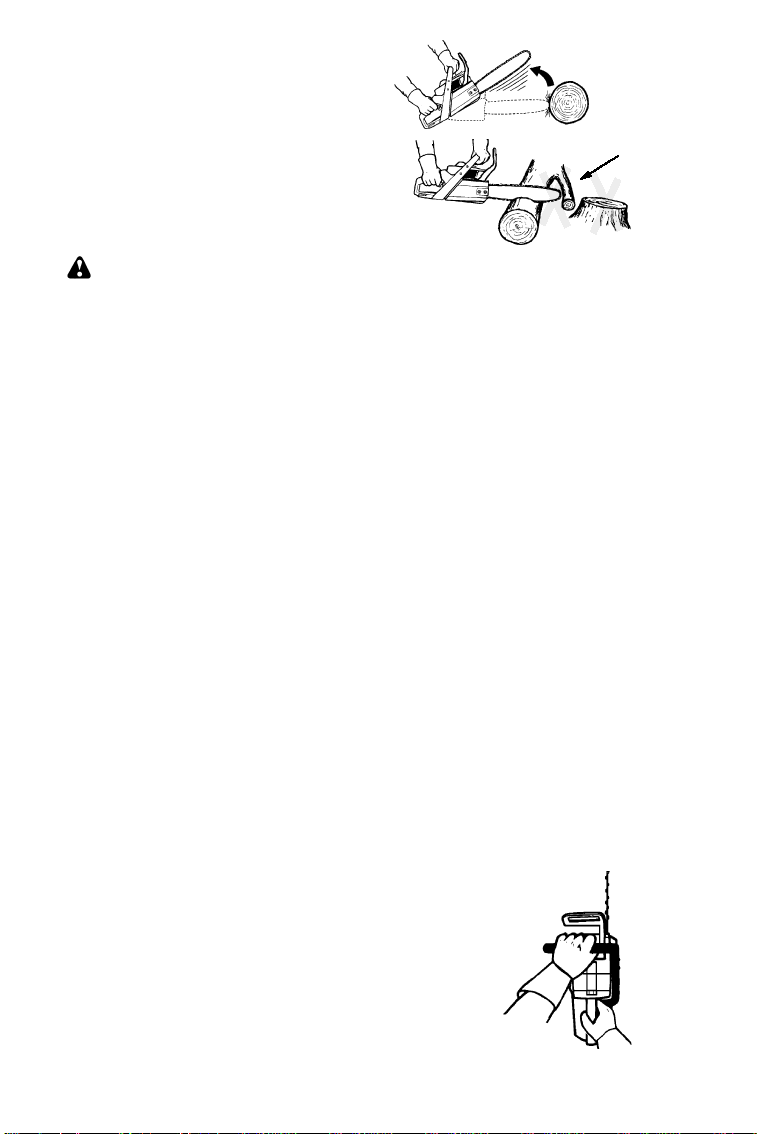
CUTTING METHODS
Place the saw on firm ground. Hold thehandles with both hands and apply full throttle.
Activate the chainbrake by turning your left
wrist against the hand guard without releasing your grip around the front handle. The
chain should stop immediately.
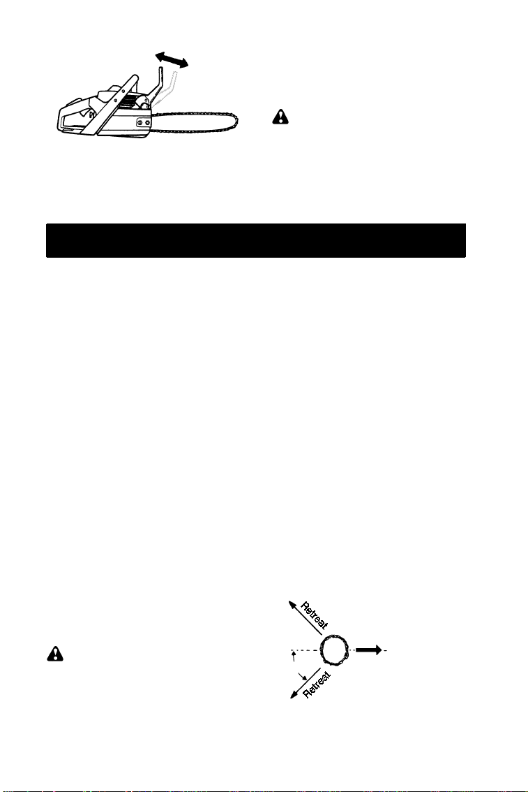
Inertia activating function control
WARNING:
lowing procedure, the engine must be turned
off.
The chain brake must be checked several
times daily. Hold thechain sawapproximately 14! (35 cm) above a stump or other firm
object. Release your grip on thefronthandle
and let the saw, by its own weight, rotate
around the rearhandle. When the tip of the
barhitsthestump,thebrakeshouldactivate.
When performing the fol-
IMPORTANTPOINTS
S Check chain tension before first use and
after 1 minute of operation. See CHAIN
TENSION in the ASSEMBLY section.
S Cut wood only. Do not cut metal, plastics,
masonry ,non- w ood buildingmate r ials, etc.
S Stopthesa wifthechainstrikesaforeignob-
ject. Inspect the saw and repair parts as
necessary.
S Keep thechainoutofdirtandsand. Evena
small amountof dirtwillquicklydullachain
and increase thepossibility of kickback.
S Practicecutting a few small logs using the
following techniquestogetthe“feel”ofusing your saw before you begin a major
sawing operation.
S Squeeze the throttle trigger and allow
the engine to reach full speed before
cutting.
S Begin cutting with the saw frame
against the log.
S Keep the engine at full speed the en-
tire time you are cutting.
S Allow the chain to cut for you. Exert
only light downward pressure.
S Release the throttle triggeras soonas
the cut is completed, allowing the engine to idle. If you run the saw at full
throttle without a cutting load, unnecessary wear can occur.
S To avoid losing control when cut is
complete, do not put pressureonsaw
at end of cut.
S Stop the engine before setting the saw
down after cutting.
TREE FELLING TECHNIQUES
WARNING:
dead branches which can fall while cutting
causingserious injury. Donotcut nearbuildingsor electricalwires if youdonotknowthe
directionof treefall, norcut atnightsince you
will not be ale to see well, nor during bad
weathersuchasrain, snow,orstrongwinds,
etc. Ifthetreemakescontactwithanyutility
line, the utility company should be notified
immediately.
Check for broken or
S Carefully plan your sawing operation in ad-
vance .
S Clear the work area. Youneed a cleararea
all around the tree so yo u can have secure
footing.
S The chain saw operator shouldkeep on the
uph illsideofth et erra inasth etreeislikelyto
roll or slide downhill after it is felled.
S Study the natural condition s that can cause
the tree to fall in a particular direction.
Natural conditions that can cause a tree to fall
in a particular dire ction include:
S The wind directionand speed.
S Thelean of the tree. The lean of a tree might
notbeapparentdueto unevenor slopingter-
rain. Use a plumb or level to determine the
direction of tree lean.
S Weight and branches on one side.
S Surrounding trees and obstacles.
Look for decay and rot. If the trunk is rotted, it
can sn apand fall toward the operator. Check
for broken or dead branches which can fall on
you while cutt ing.
Make surethere is enough ro omfor the tree to
fall. Maint ain a dista nce of
from the nearest person or other objects. Engine noise candrown out a warning call.
Remove dirt,stones, loose bark, nails,staples,
and wire from the tree where cuts are to be
made.
Plan a clear retreat path to the rear and diagonal to the line of fall.
Plan a clear retreat path
_
45
tree leng ths
2-1/2
Direction of Fall
FELLING LARGE TREES
(15 cm in diameter or larger)
The notch methodis used to fell large trees.
Anotchis cut on the side of thetreeinthedesired direction of fall. After a felling cut is
10

made on the opposite side of tree, the tree
will tend to fall into the notch.
If the tree has large buttress roots,
NOTE:
removethembeforemakingthenotch. Ifusing saw to removebuttress roots,keep saw
chainfromcontacting groundtopreventdulling of the chain.
NOTCH CUT AND FELLING THE
TREE
S Make notch cut by cutting the top of the
notch first. Cut through
ofthetree.Nextcompletethe notchbycutting the bottom of the notch. See illustration. Once the notch is cut remove the
notch of wood from the tree.
Final (felling) cut here.
2! (5 cm) above center of notch.
First cut
Notch
Second cut
S After removing the cutout of wood, make
the felling cut on the opposite side of the
notch. This is done by making a cut about
two inches higher than the center of the
notch. This will leave enoughuncut wood
between the felling cut and the notch to
form a hinge. This hinge will help prevent
thetreefrom falling in thewrongdirection.
Hinge holds tree on stump and helps
control fall
Closing
of
notch
5cm
1/3
Opening
of felling
cut
of the diameter
5cm
Hinge
CUTTINGA FALLEN TREE
(BUCKING)
Bucking is the term used for cutting a fallen
tree to the desired log length.
WARNING:
being cut. Any portion can roll causing loss
of footing and control. Do not stand downhill
of the log being cut.
IMPORTANTPOINTS
S Cut only one log at a time.
S Cut shattered wood very carefully; sharp
piecesofwoodcouldbeflungtowardoper-
ator.
S Use a sawhorseto cut small logs. Never
allow another personto holdthe log while
cuttingandneverholdthelogwith your leg
or foot.
S Do not cut in an area where logs, limbs,
androots are tangled.Drag the logs intoa
clearareabeforecuttingbypullingoutex-
posed and cleared logs first.
Do not stand on the log
TYPES OF CUTTINGUSED FOR
BUCKING
WARNING:
or hung in a log, don’t try to forceit out. You
can lose controlof the saw resulting in injury
and/or damage to the saw. Stop the saw,
drive a wedge of plastic or wood into the cut
until thesawcan beremovedeasily. Restart
thesawandcarefully reenter the cut. Do not
attempttorestartyour saw whenit is pinched
or hung in a log.
Use a wedge to remove pinched saw
Tur n saw
wooden wedge to force cut open.
Overcuttingbeginsonthetopsideof thelog
with thesaw against the log. When overcutting use light downward pressure.
Overcutting Undercutting
Ifsawbecomes pinched
OFF
and use a plastic or
: Before felling cut is complete, use
NOTE
wedges to open the cut when necessary to
controlthedirectionoffall. Toavoidkickback
and chain damage, use wood or plastic
wedges, but never steel or iron wedges.
S Be alertto signs that the tree isready to fall:
crackin gsoun ds, wide ning of thefellingcut,
or movement in the upper branches.
S As treestarts to fall, stop saw,put it down,
and get away quickly on your planned retreat path.
S DO NOTcut downa partia llyfallen treewith
your saw. Be extremely cautious with partially fallen trees that may be poorly supported. When a tre e doesn’t fall completely,
set the sawasideandpull downthe tree with
acable winch,block and tackle,ortractor.
Undercuttinginvolves cuttingon theunderside ofthelogwith top of saw against thelog.
When undercutting use light upward pressure. Hold saw firmly and maintaincontrol.
The saw will tend to push back toward you.
WARNING:
down to undercut. The saw cannot be controlled in this position.
Always make your first cut on the compression side of the log. Thecompression side of
the log is where the pressure of the log’s
weight is concentrated.
Never turn saw upside
11
First cut on compression side of log
Second cut
Second cut
First cut on compression side of log
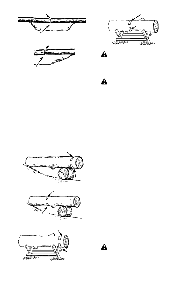
BUCKINGWITHOUT A SUPPORT
S Overcut through
log.
S Roll the log over and finish with a second
overcut.
S Watch for logs with a compression side to
prevent the saw from pinch ing. See illustration for cutting logs with a comp ression side.
of the diameter of the
1/3
BUCKING USING A LOG OR SUPPORT STAND
S Remember your first cut is always on the
compr essionsideofthelog . (Referto theillustration below for your first and second
cuts).
S Your first cut should extend
diameter of the log .
S Finish with your secondcut.
Using a log for support
2ndCut
Using a support stand
nd
2
Cut
st
1
Cut
nd
2
Cut
1stCut
1/3
1stCut
of the
1stCut
nd
Cut
2
LIMBINGAND PRUNING
WARNING:
against kickback. Do not allow the moving
chain to contact any other branches or objects at the noseofthe guide bar when limbingorpruning. Allowingsuchcontactcanresult in serious injury.
WARNING:
limb or prune. Do not stand onladders, platforms, a log, or in any position which can
cause you to loseyour balance or control of
the saw.
IMPORTANTPOINTS
S Work slowly, keeping both hands firmly
gripped on the saw. Maintainsecurefoot-
ing and balance.
S Watch out for springpoles. Use extreme
caution when cutting small size limbs.
Slender materialmaycatch the saw chain
andbe whippedtowardyou or pull you off
balance.
S Be alert for springback. Watch out for
branches that are bent or under pressure.
Avoid being struck by the branch or the
saw when the tensioninthewoodfibers is
released.
S Keep a clear work area. Frequently clear
branches out of the way to avoid tripping
over them.
LIMBING
S Alwayslimb atreeafteritiscutdown. Only
thencan limbing bedonesafely and prop-
erly.
S Leave the larger limbs underneath the
felled tree to supportthe tree as you work.
S Startatbase of thefelled tree and work to-
ward the top, cutting branches and limbs.
Removesmall limbs with one cut.
S Keepthe treebetweenyou and the chain.
Cut from the side of the tree oppositethe
branch youare cutting.
S Remove larger, supporting branches with
thecuttingtechniquesdescribedinBUCK-
ING WITHOUT A SUPPORT.
S Always use an overcut to cut small and
freely hanging limbs. Undercutting could
cause limbs to fall and pinch saw.
Be alert for and guard
Neverclimbintoatreeto
PRUNING
WARNING:
shoulder height or below. Do not cut if
branchesarehigherthanyourshoulder. Get
a professionalto do the job.
Limit pruning to limbs
12
S Makeyour first cut
the bottom of the limb.
S Next make a 2ndcutall the way through
the limb. Thencut a third overcut leaving
a1to2 inch collar from thetrunkofthetree.
of the way through
1/3
SERVICE AND ADJUSTMENTS
Third cut
Collar
Second cut
First cut
Pruning technique
WARNING:
andafteruse. Do not touchthemuffler or allow combustible material such as dry grass
or fuel to do so.
We recommendallservice and adjustments
not listed in this manual be performedby an
Authorized Service Dealer.
MAINTENANCE SCHEDULE
Check:
Fuel mixture level Before each use....
Bar lubrication Before each use.......
Chain tension Before each use.......
Chain sharpness Before each use....
For damaged parts Before each use..
For loose caps Before each use......
For loose fasteners Before each use...
For loose parts Before each use......
Inspect and Clean:
Bar Before each use................
Complete saw After each use.......
Air filter Every 5 hours*.............
Chain brake Every 5 hours*........
Spark arresting screen
and muffler Every 25 hours*.........
Replace spark plug
Replace fuel filter
* Hours of Operation
Mufflerisvery hotduring
Yea rly.
Yea rly...
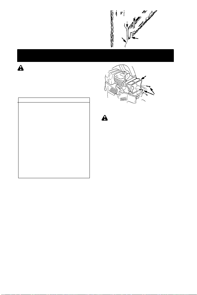
AIR FILTER
CAUTION
or other flammable solventto avoidcreating
a firehazard or producingharmful evaporative emissions.
Cleaning the air filter:
A dirty air filter decreases engine performance and increases fuel consumption and
harmful emissions. Always clean after 15
tanks of fuel or 5 hours of operation, whichever comes first. Clean more frequently in
dusty conditions. A used air filter can never
becompletely cleaned. It is advisable toreplaceyourairfilter witha newoneafterevery
50hoursofoperation,orannually,whichever
comes fir st.
1. Loosen 3 screwson cylinder cover.
2. Remove cylinder cover.
3. Remove air filter.
4. Clean the air filterusinghotsoapywater.
Rinsewithcleancoolwater. Airdrycompletely before reinstalling.
5. Reinstall air filter.
6. Reinstall cylinder cover and 3 screws.
TIghten securely.
Do not cleanfilter in gasoline
:
Air Filter
Air Filter
Screws
CARBURETOR ADJUSTMENTS
WARNING:
during most of this procedure. Wear your
protective equipmentandobserve all safety
precautions.Thechainmust notmoveatidle
speed.
The carburetor has been carefully set at the
factory. Adjustments may be necessary if
you noticeany of the followingconditions:
S Chain moves at idle. See IDLESPEED--T
adjusting procedure.
S Sawwill not idle. SeeIDLESPEED--T ad-
justing procedure.
Idle Speed---T
Allow engine to idle. If the chain moves,idle
istoofast. Iftheenginestalls,idleis tooslow.
Adjust speed untilengineruns withoutchain
movement (idle too fast) or stalling (idle too
s l ow ) . T he i dl e s peed s c r ew is labeled "T".
S Tur n i dl e s peed s c r ew ( T ) c l oc k w i s e t o i n-
crease engine speed.
S Turn idle speed screw (T) counterclock-
wise to decrease engine speed.
If you require further assistanceor are unsure
about performing this procedure, contact your
aut h orizedservicedealer.
BAR MAINTENANCE
If your saw cuts to one side, hastobeforced
throughthecut,orbeenrunwithanimproper
amount of bar lubrication it may be necessarytoservice yourbar. Awornbar will damage your chain and make cutting difficult.
After each use, ensure ON/STOP switch is
in the STOP position,thenclean allsawdust
from the guide bar and sprocket hole.
To maintainguide bar:
S MoveON/STOPswitch to the STOPposi-
tion.
S Loosenand removechain brake nuts and
chain brake. Remove bar and chain from
saw.
Thechainwill bemoving
13

S Clean the oil holes and bar groove after
each 5 hours of operation.
Remove Sawdust From
Guide Bar Groove
Oil Holes
S Burring of guide bar rails is a normal
process of rail wear. Removethese burrs
with a flat file.
S Whenrailtopisuneven,useaflatfiletore-
store square edges and sides.
Replace guide barwhen the grooveis worn,
the guide bar is bent or cracked, or when
excess heatingorburringoftherailsoccurs.
If replacement is necessary, use only the
guidebar specifiedforyoursaw intherepair
partslist or on the decal locatedon thechain
saw.
CHAIN SHARPENING
Chain sharpening is a complicatedtask that
requires special tools. We recommended
you refer chainsharpeningto a professional
chain sharpener.
IGNITION TIMING
Ignition timing is fixedand nonadjustable.
SPARK PLUG
The spark plug should be replaced each
year to ensure the engine starts easier and
runs better.
1. Loosen 3 screwson cylinder cover.
2. Remove the cylinder cover.
3. Pull off the spark plug boot.
4. Remove spark plug from cylinder and
discard.
5. Replace with Champion RCJ--7Y spark
plug and tighten securely with a 3/4 inch
(19mm) socket wrench. Spark plug gap
should be 0.025 inches (0,6 mm).
File Rail Edges
and Sides
Square
CorrectGrooveWorn Groove
6. Reinstall the spark plug boot.
7. Reinstall the cylinder cover and 3
screws. Tighten securely.
Spark PlugBoot
STORAGE
WARNING:
cool, and secure the unit before storing or
transporting in a vehicle. Store unit and fuel
in an area where fuel vapors cannot reach
sparks or open flames from water heaters,
electric motors or switches, furnaces, etc.
Storeunitwithallguardsinplace.Positionso
that any sharp object cannot accidentally
cause injuryto passersby. Store the unit out
of reachof children.
S Before storing, drain all fuel from the unit.
Start engine and allow to rununtil it stops.
S Clean the unit before storing. Pay particu-
lar attention to the air intake area, keeping
it free of debris.Use a mild detergent and
sponge to clean the plastic surfaces.
S Donotstoretheunit or fuel in a closed area
where fuel vapors can reach sparks or an
openflamefromhotwater heaters,electric
motors or switches, furnaces,etc.
S Storein a dry area out of the reach of chil-
dren.
CAUTION
deposits from forming in essential fuel system parts such as the carburetor, fuel filter,
fuel hose, or fuel tank during storage. Alcohol blended fuels (called gasohol or using
ethanol or methanol) can attract moisture
which leads to fuel mixture separation and
formationofacids during storage. Acidicgas
can damage the engine.
Stopengineandallowto
It is importanttoprevent gum
:
14

TROUBLESH
O
O
WARNING:
therecommendedremediesbelow except remediesthatrequireoperationoftheunit.
TINGTABLE
Always stop unit and disconnect sparkplug beforeperforming all of
TROUBLE CAUSE REMEDY
Enginewill not
start or will run
only a few
seconds after
starting.
Enginewill
notidle
properly.
Enginewill not
accelerate,
lacks power,
or dies under
a load.
Engine
smokes
excessively.
Chain moves
at idlespeed.
1. Ignition switch off.
2. Engine flooded.
3. Fuel tank empty.
4. Spark plug not firing.
5. Fuel not reaching
carburetor.
1. Carburetor requires
adjustment.
2. Crankshaft seals worn.
1. Air filterdirty.
2. Spark plug fouled.
3. Chain brake engaged.
4. Carburetor requires
adjustment.
1. Too much oil mixed with
gasoline.
1. Idlespeed requires
adjustment.
2. Clutchrequires repair.
LIMITED WARRANTY STATEMENT
SECTION 1: LIMITED WARRANTY
Husqvarna Forest & Garden Company
(”Husqvarna”) wa rrants Husqvarna product
tothe origina lpurchaserto be free from defects
in material and workmanship from the date of
purchase for the “Warranty Period” of the products as set forth below:
Lifetime Warranty: All tiller tines against
breakage, trimmer shafts, ignition coils and
modules on hand held product.
3 Year Warranty: Spindles (on Zero Turn
Riders and Commercial Walk--Behinds)
2 Year COMMERCIAL Warranty: Husqvarna Commercial Turf Equipment -- zero
turnriders, wide area walks, and groundengaging commercial equipment.
2 Year NON--COMMERCIAL Warranty: Automatic mower, riding lawn mowers, yard and
gar den tractor s, walk behind mowers, tillers,
chain saws, trimmers, brushcutte rs, cle a ring
saws, sno wblowers, handheld blowers,backpack blowers,hedge trimmers, electrical pro
ucts and power--as sist collection systems for
non--commercial, non--p r ofess ional,non--institutional or non- -income producing use, except
as herein stated
Emission control system compon e nts nece ssary to comply with CARB--TIER II and EPA
regulations, except for those components
which are part of engine systems manufactured by third party engine manufacturers for
which the purchaser has received a separate
.
d-
1. Move ignitionswitch to ON.
2. See “Difficult Starting”in
Operation Section.
3. Fill tank with correct fuel mixture.
4. Install new sparkplug.
5. Check for dirty fuelfilter; replace.
Check for kinked or split fuel line;
repair or replace.
1. See “Carburetor Adjustment” in the
Service and Adjustments Section.
2. Contactan authorizedservice dealer.
1. Cleanor replace air filter.
2. Cleanor replace plug and regap.
3. Disengagechain brake.
4. Contactan authorizedservice dealer.
1. Empty fuel tank and refill with
correct fuel mixture.
1. See “CarburetorAdjustment” in the
Service and Adjustments Section.
2. Contactan authorizedservice dealer.
warranty with product information supplied at
time of purchase.
1 Year Warranty: Power cutters, stump
grinder,poleprunersandpolesawsfor non-commercial, non--professional, non--institutionalornon--incomeproducinguse.All trimmers, brushcutters,clearingsaws, hovering
trimmers, stick edgers, backpack blowers,
hand held blowers, hedge trimmers, and
power--assist collection systems used for
commercial, institutional, professional, or income producing purposes or use.
Batteries have a one year prorated limited
warranty with 100% replacement during the
first 6 months.
90 Day Warranty: Automatic mower, chain
saws, power cutters, stump grinders, pole
saws, pole pruners,snow throwers,model series 580 & 600 walk--behindmowers, and commercial turfequipmentor anyHusqvarnaproduct used fo r commercial, institution al,
professional, or income producingpurposes or
use except as otherwise provided herein.
Husqvarna Safe ty Appa rel carries a 90- -day
warrantyfrom the date of the customer’s original purchase for defects inmaterial and workmanship. Normal wear, tear or abuse is not
covered under warranty. Product must be returned to Charlotte with a warranty claim form.
All care and maintena nceinstructionsmust be
followed as stated by the manufacturer on the
15

carela bel. Thef itoftheprotectiveappa rel/b oot
is not covered under warranty.
30 Day Warranty: Replacement parts, accessories including bars and chains, tools and
display items.
SECTION 2: HUSQVARNA’S OBLIG ATIONS UNDER THE WARR ANTY
Husqvarnawill repair or replacedefectivecomponents without charge for parts or labor if a
componentfails because of adefect in ma terial
or workmanship during the warranty period.
SECTION 3: ITEMS NOT COVERED
BY THIS WARR ANTY
The follo wing items are not covered by this
warranty:
(1)Normal customer maintenance items
whichbecomewornthroughnormalregular use, including,but not limitedto, belts,
blades, blade adapters, bulbs, filters,
guide bars, lubricants, rewind springs,
saw chains, spark plugs, starter ropes
and tines;
(2)Naturaldiscolorationofmaterialduetoul-
traviolet light.
(3)Engine and drive systems not manufac-
turedbyHusqvarna;theseitems arecovered by the respective manufacturer ’s
warranty as provided in writing with the
product information supplied at the time
ofpurchase;allclaims must besent tothe
appropriate manufacturer.
(4)Lawn and garden attachments are cov-
ered by a thirdparty which gives a warranty; all claims for warranty should be
sent to the manufacturer; and
(5)Emission control system components
necessaryto comply with CARB--TIERII
andEPAregulations which are manufactured by third party engine manufacturer.
SECTION 4: EXCEPTIONS AND
LIMITATIONS
This warranty shall be inapplicable to defects resulting from the following:
(1)Accident,abuse,misuse, negligenceand
neglect, including stale fuel, dirt, abrasives, moisture, rust, corrosion, or any
adversereactionduetoincorrect storage
or use habits.
(2)Failuretoope r ateormaintaintheunitinac-
cordance with the instructionmanual or instruct ion sheet furnishedby Husqvarna.
(3)Alterations or modifications that change
theintended use of the product oraffects
the product’s performance, operation,
safety,or durability,orcauses theproduct
tofail tocomply with any applicablelaws.
(4)Additional damage to parts or compo-
nents due to continued use occurringaf-
ter any of the above.
REPAIR OR REPLACEMENT AS PROVIDED UNDER THIS WARRANTY IS THE
EXCLUSIVE REMEDY OF THE PURCHASER. HUSQVARNA SHALL NOT BE
LIABLEFOR ANY INCIDENTAL OR CONSEQUENTIAL DAMAGES FOR BREACH
OF ANY EXPRESS OR IMPLIED WARRANTY ON THESE PRODUCTS EXCEPT
TOTHE EXTENT PROHIBITED BYAPPLICABLE LAW. ANY IMPLIED WARRANTY
OR MERCHANTABILITY OR FITNESS
FOR A PARTICULAR PURPOSE ON
THESEPRODUCTSIS LIMITED INDURATION TO THE WARRANTY PERIOD AS
DEFINED IN THE LIMITED WARRANTY
STATEMENT. HUSQVARNA RESERVES
THE RIGHT TO CHANGE OR IMPROVE
THE DESIGN OF THE PRODUCT WITHOUT NOTICE, AND DOES NOT ASSUME
OBLIGATION TO UPDATE PREVIOUSLY
MANUFACTURED PRODUCTS.
Some states do not allow the exclusionof incidentalor consequential dama ges,orlimitations
on how lo ngan implied warranty lasts, so the
above limitations or exclusions may not apply
to you. Th is warranty gives youspecif ic legal
rights, and you may also have other rights
which vary from state to state.
SECTION 5: CUSTOMER RESPONSIBILITIES
The product must exhibit reasonable care,
maintenance, operation, storage and general
upkeep as written in the maintenance section
of the Owner’s/Operator’s manual. Shouldan
operational problem or failure occur, the productshould not be used, but deliveredasis to an
authorized Husqvarna dealer for evaluation.
Proof of purchase, as explained in Section 6,
rests solely with the customer .
SECTION 6: PROCEDURE TO OBTAIN WARRANTY CONSIDERATION
It is the Owner’s and Dealer’s responsibility
to makecertain that the Warranty Registration Card is properly filled outand mailed to
HusqvarnaForest&GardenCompany. This
card should be mailed within ten (10) days
from the date of purchaseinordertoconfirm
the warranty and to facilitate post--sale service.
Proof of purchasemust bepresented to the
authorized Husqvarna dealer in order to obtain warranty service. This proof must include date purchased, model number,serial
number,andcompletename and addressof
the selling dealer.
To obtain the benefit of this warranty, the
productbelieved tobedefectivemust bedelivered to anauthorizedHusqvarna dealer in
atimely manner,nolaterthanthirty (30)days
from date of the operational problemor failure. The product must be delivered at the
owner’s expense. Pick--up and delivery
charges are not covered by this warranty.
AnauthorizedHusqvarnadealercanbenormally located through the “Yellow Pages” of
the local telephone directory or by calling
1--800--HUSKY62 for a dealer in your area.
7349 StatesvilleRoad
CHARLOTTE,NC 28269
16

U.S. EPA / ENVIRONMENT CANADA
EMISSION CONTROL WARRANTY STATEMENT
YOUR WARRANTY RIGHTS AND OBLIGATIONS: The U. S. Environmental
Protection Agency, Environment Canada
and HUSQVARNA are pleased to explain
the emissions control system warranty on
your year 2002--2004small off--roadengine.
HUSQVARNA must warrant the emission
controlsystemonyoursmalloff--roadengine
for the periods of time listed below provided
therehasbeennoabuse, neglect, orimproper maintenance of your small off--road engine.Youremission control system includes
partssuch as the carburetorandtheignition
system. Where a warrantablecondition exists,HUSQVARNAwillrepairyour smalloff-roadengineat nocost toyou.Expensescoveredunderwarrantyincludediagnosis,parts
andlabor. MANUFACTURER’SWARRAN-
TY COVERAGE: If any emissions related
part on your engine (as listed under Emissions Control Warranty Parts List) is defective or a defect in the materialsorworkmanship of the enginecausesthefailure of such
an emission relatedpart, the part will be repairedorreplacedbyHUSQVARNA. OWN-
ER’S WARRANTY RESPONSIBILITIES:
As the small off--road engine owner, you are
responsible for the performance of the requiredmaintenance listed in your instruction
manual. HUSQVARNA recommends that
youretain all receipts coveringmaintenance
on your small off--road engine, but HUSQVARNA cannot deny warrantysolely for the
lack of receipts or for your failure to ensure
the performance of all scheduled maintenance. As thesmall off--roadengineowner,
you should be aware that HUSQVARNA
may deny you warranty coverage if your
small off--road engine or a part of ithasfailed
due to abuse, neglect, improper maintenance,unapprovedmodifications,ortheuse
ofpartsnotmadeorapprovedby theoriginal
equipment manufacturer. Youareresponsibleforpresentingyoursmall off--roadengine
to a HUSQVARNA authorized repair center
as soon as a problem exists. Warranty repairs should be completed in a reasonable
amountoftime,nottoexceed30days. If you
haveany questions regardingyourwarranty
rights and responsibilities, you should contact your nearest authorized service center
or call HUSQVARNA at 1--800--487--5962.
WARRANTY COMMENCEMENT DATE:
The warranty period begins on the date the
small off--road engine is purchased.
LENGTH OF COVERAGE: This warranty
shall befor a period oftwoyears from theinitial date of purchase. WHATISCOVERED:
REPAIR OR REPLACEMENT OF PARTS.
Repair or replacementofanywarrantedpart
will be performed at no charge to the owner
at an approved HUSQVARNA servicing
center.If you have any questions regarding
your warranty rights and responsibilities,
you should contactyour nearest authorized
service center or call HUSQVARNA at
1--800--487--5962. WARRANTY PERIOD:
Any warranted part which is not scheduled
forreplacementasrequiredmaintenance,or
which is scheduled only for regular inspection to the effect of“repair orreplace as necessary” shall be warranted for 2 years. Any
warranted part which is scheduled for replacementas requiredmaintenanceshallbe
warrantedfortheperiodoftime up to thefirst
scheduled replacement point for that part.
DIAGNOSIS: The owner shall not be
charged for diagnostic labor which leads to
thedeterminationthatawarrantedpartisdefective if thediagnosticwork isperformedat
an approved HUSQVARNA servicing center. CONSEQUENTIAL DAMAGES:
HUSQVARNAmay be liable for damages to
otherenginecomponentscausedby the failure of a warranted part still under warranty.
WHAT IS NOT COVERED: All failures
causedbyabuse,neglect,orimpropermaintenance are not covered. ADD--ON OR
MODIFIED PARTS: The use of add--on or
modified parts can be grounds for disallowingawarrantyclaim. HUSQVARNAis notliable to cover failures of warranted parts
caused by the use of add--on or modified
parts. HOW TO FILE A CLAIM:If you have
any questions regarding your warranty
rights and responsibilities, you should contact your nearest authorized service center
or call HUSQVARNA at 1--800--487--5962.
WHERE TO GET WARRANTY SERVICE:
Warranty services or repairs shall be provided at all HUSQVARNA service centers.
Call 1--800--487--5962. MAINTENANCE,
REPLACEMENT AND REPAIR OF EMISSION RELATED PARTS:Any HUSQVAR-
NA approved replacement part used in the
performance of any warranty maintenance
or repair on emission related parts will be
provided without charge to the owner if the
part is under warranty. EMISSION CON-
TROLWARRANTYPARTSLIST:Carburetor,IgnitionSystem: SparkPlug(coveredup
to maintenance schedule), Ignition Module.
MAINTENANCE STATEMENT: The owner
is responsible for the performanceof all required maintenance as defined in the instruction manual.
17

The informationon the product label indicates which standard your engine is certified.
Example: (Year)EPA Phase 1 or Phase 2 and/or CALIFORNIA.
This engine is certified to be emissions compliant for the following use:
Moderate (50hours)
Intermediate (125hours)
Extended (300 hours)
18
 Loading...