

Husaberg fe 450 2009, fe 570 2009 Repair manual
REPAIR MANUAL
FE 450 EU
FE 450 AUS
FE 450 USA
FE 570 EU
FE 570 AUS
FE 570 USA
2009
Article no. 3803004en


INTRODUCTION 1
INTRODUCTION
It is important that you read this owner's manual carefully and completely before the start of work.
Only use ORIGINAL HUSABERG SPARE PARTS.
This vehicle can only fulfill the demands placed on it in the long run if the specified service work is performed regularly by qualified
experts.
The repair manual was written to correspond to the most current state of this model series. We reserve the right to make changes in
the interest of technical advancement without, at the same time, updating this repair manual.
We shall not provide a description of general workshop methods. Likewise, safety rules that apply in a workshop are not specified here.
It is assumed that repair work will be performed by a fully trained mechanic.
All specifications are non-binding. HUSABERG, a division of KTM SMC AG (referred to herein as HUSABERG), specifically reserves
the right to modify or delete technical specifications, prices, colors, forms, materials, services, designs, equipment, etc., without prior
notice and without specifying reasons, to adapt these to local conditions, as well as to stop production of a particular model without
prior notice. HUSABERG accepts no liability for delivery options, deviations from illustrations and descriptions or misprints and other
errors. The models portrayed partly contain special equipment that does not belong to the regular scope of delivery.
© 2008 by HUSABERG eine Division der KTM SMC AG, Mattighofen Austria
All rights reserved
Reproduction, even in part, is permitted only with the express written permission of the copyright owner.
ISO 9001(12 100 6061)
Within the meaning of the international quality management standard ISO 9001, HUSABERG uses quality assurance
processes that lead to the maximum possible quality of the products.
Issued by: TÜV Management Service
HUSABERG eine Division der KTM SMC AG
5230 Mattighofen, Austria

CONTENTS 2
CONTENTS
MEANS OF REPRESENTATION ............................................ 5
IMPORTANT NOTES ............................................................ 6
LOCATION OF SERIAL NUMBERS ........................................ 7
Chassis number............................................................... 7
Type label (FE EU, FE AUS) ............................................. 7
Type label (FE USA) ........................................................ 7
Key number (FE EU, FE AUS)........................................... 7
Engine number................................................................ 7
Fork part number............................................................. 8
Shock absorber part number ............................................. 8
MOTORCYCLE..................................................................... 9
Jacking up the motorcycle................................................ 9
Removing the motorcycle from the work stand.................... 9
Starting .......................................................................... 9
01/FORK, TRIPLE CLAMP.................................................. 10
Adjusting the compression damping of the fork ................ 10
Adjusting the rebound damping of the fork....................... 10
Adjusting the spring preload of the fork ........................... 10
Bleeding the fork legs .................................................... 11
Cleaning the dust boots of the fork legs ........................... 11
Loosening the fork protection.......................................... 11
Positioning the fork protection ........................................ 12
Removing the fork legs................................................... 12
Installing the fork legs ................................................... 12
Removing the fork protector............................................ 13
Installing the fork protector ............................................ 13
Performing a fork service ................................................ 14
Disassembling the fork legs ............................................ 14
Cartridge disassembly .................................................... 17
Disassembling the compression damping fitting ............... 19
Checking the fork legs.................................................... 19
Assembling the compression damping fitting.................... 20
Assembling the cartridge ................................................ 21
Assembling the fork legs ................................................ 23
Greasing the steering head bearing.................................. 27
Removing the lower triple clamp ..................................... 27
Installing the lower triple clamp ...................................... 28
Checking the play of the steering head bearing................. 29
Adjusting the play of the steering head bearing ................ 29
03/FRAME........................................................................ 30
Removing the engine guard ............................................ 30
Installing the engine guard ............................................. 30
04/SHOCK ABSORBER, SWINGARM................................... 31
Adjusting the high-speed compression damping of the
shock absorber.............................................................. 31
Adjusting the low-speed compression damping of the
shock absorber.............................................................. 31
Adjusting the rebound damping of the shock absorber....... 32
Measuring rear wheel sag unloaded ................................. 32
Checking the static sag of the shock absorber .................. 32
Checking the riding sag of the shock absorber .................. 33
Adjusting the spring preload of the shock absorber ........... 33
Adjusting the riding sag ................................................. 34
Removing the shock absorber ......................................... 34
Installing the shock absorber .......................................... 34
Performing a shock absorber service ................................ 35
Removing the spring ...................................................... 35
Disassembling the shock absorber ................................... 36
Disassembling the piston rod .......................................... 37
Disassembling the seal ring retainer ................................ 38
Replacing the pilot bushing ............................................ 39
Checking the shock absorber .......................................... 39
Disassembling the rebound adjuster ................................ 40
Removing the heim joint ................................................ 41
Installing the heim joint ................................................. 41
Assembling the rebound adjuster .................................... 42
Assembling the seal ring retainer .................................... 43
Assembling the piston rod .............................................. 43
Assembling the shock absorber ....................................... 45
Bleeding and filling the shock absorber ........................... 47
Filling the shock absorber with nitrogen ........................... 49
Installing the spring....................................................... 50
Removing the swingarm, with shock absorber and rear
wheel ........................................................................... 51
Installing the swingarm, with shock absorber and rear
wheel ........................................................................... 52
05/EXHAUST .................................................................... 54
Removing the main silencer............................................ 54
Installing the main silencer ............................................ 54
Removing the exhaust system ......................................... 54
Installing the exhaust system.......................................... 55
06/AIR FILTER.................................................................. 57
Removing the air filter ................................................... 57
Installing the air filter .................................................... 57
Cleaning air filter........................................................... 57
07/FUEL TANK, SEAT, TRIM.............................................. 59
Removing the seat ......................................................... 59
Mounting the seat ......................................................... 59
Removing the fuel tank .................................................. 59
Installing the fuel tank ................................................... 60
Removing the spoiler ..................................................... 61
Installing the spoiler ...................................................... 61
Checking the fuel pressure ............................................. 62
08/MASK, FENDER, DECAL ............................................... 63
Removing the front fender .............................................. 63
Installing the front fender............................................... 63
Removing the start number plate (FE USA) ...................... 63
Installing the start number plate (FE USA)....................... 64
09/FRONT WHEEL ............................................................ 65
Removing the front wheel ............................................... 65
Installing the front wheel................................................ 65
Checking the tire air pressure ......................................... 66
Checking the tire condition............................................. 66
Checking the brake disks................................................ 67
10/REAR WHEEL .............................................................. 68
Removing the rear wheel ................................................ 68
Installing the rear wheel ................................................. 68
Checking the chain tension ............................................ 69
Adjusting the chain tension ............................................ 69
Checking the chain wear ................................................ 70
Checking the rear sprocket/engine sprocket for wear ......... 71
Checking for chain dirt accumulation .............................. 71
Cleaning the chain......................................................... 71
Adjusting the chain guide............................................... 72
Checking the spoke tension ............................................ 72
11/WIRING HARNESS, BATTERY ....................................... 73
Disconnecting the negative cable of the battery ................ 73
Connecting the negative cable of the battery .................... 73
Changing the main fuse ................................................. 73
Changing the fuses of individual power consumers............ 74
Removing the battery ..................................................... 75
Installing the battery...................................................... 75
Charging the battery ...................................................... 76

CONTENTS 3
13/BRAKE SYSTEM........................................................... 78
Checking the free travel of the hand brake lever ............... 78
Adjusting the free travel of the handbrake lever (FE EU,
FE AUS) ....................................................................... 78
Adjusting the basic position of the handbrake lever
(FE USA) ...................................................................... 78
Checking the front brake fluid level ................................. 79
Adding front brake fluid ................................................. 79
Checking the front brake linings...................................... 80
Changing the front brake linings ..................................... 80
Checking the free travel of the foot brake lever ................. 82
Adjusting the basic position of the footbrake lever ............ 82
Checking the rear brake fluid level .................................. 83
Adding rear brake fluid .................................................. 83
Checking the rear brake linings ....................................... 84
Changing the rear brake linings....................................... 84
14/LIGHTING SYSTEM, INSTRUMENTS ............................. 86
Adjusting the speedometer functions ............................... 86
Setting kilometers or miles ............................................. 86
Activating the additional functions .................................. 87
Setting the wheel circumference ..................................... 87
Setting the clock ........................................................... 88
Removing the headlight mask with the headlight (FE EU,
FE AUS) ....................................................................... 88
Installing the headlight mask with the headlight (FE EU,
FE AUS) ....................................................................... 88
Checking the headlight adjustment (FE EU, FE AUS)........ 89
Adjusting the beam width of the headlight (FE EU,
FE AUS) ....................................................................... 89
Changing the headlight bulb (FE EU, FE AUS) ................. 89
30/ENGINE....................................................................... 91
Removing the engine ..................................................... 91
Installing the engine ...................................................... 94
30/ENGINE DISASSEMBLY................................................ 99
Clamping the engine in the engine work stand.................. 99
Draining the engine oil ................................................... 99
Removing the oil line ..................................................... 99
Removing the starter motor ............................................ 99
Removing the oil filter.................................................... 99
Removing the valve cover ............................................. 100
Removing the spark plug .............................................. 100
Removing the generator cover ....................................... 100
Positioning the engine at ignition top dead center
(TDC) ......................................................................... 100
Removing the timing chain tensioner............................. 101
Removing the camshaft................................................ 101
Removing the cylinder head.......................................... 102
Removing the piston .................................................... 102
Removing the distance bushing .................................... 102
Removing the rotor ...................................................... 103
Removing the balance weight ....................................... 103
Removing the timing chain guide rail ............................ 103
Removing the timing chain tensioning rail...................... 103
Removing the timing chain securing guide ..................... 104
Removing the timing chain ........................................... 104
Removing the ignition pulse generator ........................... 104
Removing the water pump cover ................................... 104
Removing the clutch cover ........................................... 104
Disassembling the clutch disks ..................................... 105
Removing the primary gear nut ..................................... 105
Removing the outer clutch hub ..................................... 106
Removing the balancer shaft ........................................ 106
Removing the primary gear ........................................... 106
Removing the free wheel gear ....................................... 107
Removing the torque limiter ......................................... 107
Removing the starter idler gear ..................................... 107
Removing the oil pump gears........................................ 107
Removing the oil pumps............................................... 108
Removing the shift shaft .............................................. 108
Removing the shift drum locating unit ........................... 108
Removing the locking lever ........................................... 108
Removing the left section of the engine case.................. 109
Removing the shift rails ............................................... 109
Removing the shift drum .............................................. 109
Removing the shift forks .............................................. 109
Removing the diaphragm.............................................. 110
Removing the transmission shafts ................................. 110
Removing the crankshaft .............................................. 110
30/ENGINE - WORK ON THE INDIVIDUAL PARTS ............. 111
Working on the right section of the engine case .............. 111
Working on the left section of the engine case................ 112
Removing the oil pressure regulator valve....................... 113
Checking the spring length of the oil pressure regulator
valve .......................................................................... 113
Installing the oil pressure regulator valve ....................... 113
Removing the crankshaft seal ring in the clutch cover ..... 113
Installing the crankshaft seal ring in the clutch cover...... 114
Removing the water pump ............................................ 114
Installing the water pump............................................. 115
Checking the balancer shaft ......................................... 115
Removing the timing chain sprocket .............................. 116
Installing the timing chain sprocket............................... 116
Removing the crankshaft bearing inner ring.................... 116
Installing the crankshaft bearing inner ring .................... 117
Changing the conrod bearing ........................................ 117
Checking the crankshaft run-out at the bearing pin ......... 119
Measuring the crankshaft end play ................................ 119
Checking/measuring the cylinder................................... 120
Checking/measuring the piston ..................................... 120
Checking the piston ring end gap .................................. 121
Piston/cylinder - determining the mounting clearance ..... 121
Checking the oil pumps for wear ................................... 122
Disassembling the autodecompressor ............................ 122
Assembling the autodecompressor................................. 123
Checking the camshaft................................................. 123
Checking the timing assembly ...................................... 124
Preparing the timing chain tensioner for installation ....... 124
Removing the coolant temperature sensor ...................... 125
Removing the rocker arm.............................................. 125
Removing the valves .................................................... 125
Changing the camshaft bearing ..................................... 126
Checking the valves ..................................................... 127
Checking the valve springs ........................................... 127
Checking the valve spring seat ...................................... 127
Checking the cylinder head .......................................... 128
Installing the valves..................................................... 128
Installing the rocker arm .............................................. 129
Installing the coolant temperature sensor....................... 129
Checking the clutch..................................................... 130
Checking the shift mechanism ...................................... 131
Preassembling the shift shaft........................................ 132
Disassembling the main shaft ....................................... 132
Assembling the main shaft ........................................... 132
Disassembling the countershaft .................................... 133

CONTENTS 4
Assembling the countershaft......................................... 133
Checking the transmission............................................ 134
Checking the electric starter mode ................................ 135
Removing the free wheel .............................................. 135
Installing the free wheel ............................................... 136
30/ENGINE ASSEMBLY................................................... 137
Installing the crankshaft............................................... 137
Installing the transmission shafts .................................. 137
Installing the diaphragm .............................................. 137
Installing the shift fork................................................. 138
Installing the shift drum............................................... 138
Installing the shift rails ................................................ 138
Installing the left engine case ....................................... 138
Installing the locking lever............................................ 139
Installing the shift drum locating unit............................ 139
Installing the shift shaft ............................................... 139
Installing the oil pumps ............................................... 140
Installing the oil pump gears ........................................ 140
Installing the starter idler gear ...................................... 140
Installing the torque limiter .......................................... 141
Installing the free wheel gear ........................................ 141
Installing the primary gear ............................................ 141
Installing the balancer shaft ......................................... 141
Installing the outer clutch hub ...................................... 141
Installing the primary gear nut ...................................... 142
Installing the clutch discs ............................................ 142
Installing the clutch cover ............................................ 143
Installing the water pump cover .................................... 143
Installing the ignition pulse generator ............................ 143
Installing the timing chain............................................ 144
Installing the timing chain securing guide...................... 144
Installing the timing chain tensioning rail ...................... 144
Installing the timing chain guide rail ............................. 144
Installing the balance weight ........................................ 144
Installing the rotor....................................................... 145
Installing the distance bushing ..................................... 145
Installing the piston..................................................... 145
Installing the cylinder head .......................................... 147
Installing the camshaft ................................................ 148
Installing the timing chain tensioner ............................. 148
Checking the valve clearance ........................................ 148
Adjusting the valve clearance........................................ 149
Installing the generator cover........................................ 149
Installing the spark plug............................................... 150
Installing the valve cover .............................................. 150
Installing the oil filter .................................................. 150
Installing the oil screen ................................................ 150
Assembling the starter motor ........................................ 151
Installing the oil line .................................................... 151
Removing the engine from the work stand ...................... 151
32/CLUTCH .................................................................... 152
Checking the fluid level of the hydraulic clutch .............. 152
Changing the hydraulic clutch fluid ............................... 152
35/WATER PUMP, COOLING SYSTEM .............................. 154
Checking the coolant level............................................ 154
Checking the antifreeze and coolant level ...................... 154
Draining the coolant .................................................... 155
Refilling coolant.......................................................... 155
38/LUBRICATION SYSTEM .............................................. 156
Oil circuit ................................................................... 156
Checking the engine oil pressure................................... 156
Checking the engine oil level ........................................ 158
Adding engine oil ........................................................ 158
Changing the engine oil and oil filter, cleaning the
engine oil screen ......................................................... 158
Draining engine oil, cleaning engine oil screen ............... 158
Removing the oil filter.................................................. 159
Installing the oil filter .................................................. 160
Filling up with engine oil .............................................. 160
41/THROTTLE VALVE BODY............................................. 161
Idle speed adjusting screw ........................................... 161
Taking off the throttle valve body and allowing it to
hang to the side .......................................................... 161
Installing the throttle valve body ................................... 162
Adjusting the idle speed............................................... 163
FAULT CODE .................................................................. 164
TECHNICAL DATA - ENGINE ............................................ 219
Capacity - engine oil .................................................... 219
Capacity - coolant........................................................ 219
TECHNICAL DATA - ENGINE TOLERANCES, WEAR
LIMITS........................................................................... 220
TECHNICAL DATA - ENGINE TIGHTENING TORQUES........ 222
TECHNICAL DATA - CHASSIS .......................................... 224
Lighting equipment ..................................................... 224
Tires .......................................................................... 225
Capacity - fuel............................................................. 225
TECHNICAL DATA - FORK................................................ 226
TECHNICAL DATA - SHOCK ABSORBER ........................... 227
TECHNICAL DATA - CHASSIS TIGHTENING TORQUES ...... 228
CLEANING/PROTECTION ................................................. 229
Cleaning the motorcycle............................................... 229
Protection for winter operation ...................................... 230
STORAGE ....................................................................... 231
Storage....................................................................... 231
Putting into operation after storage ............................... 231
SERVICE SCHEDULE....................................................... 232
Important maintenance work to be carried out by an
authorized HUSABERG workshop .................................. 232
Important maintenance work to be carried out by an
authorized HUSABERG workshop. (as additional order) ... 233
Important checks and maintenance work to be carried
out by the rider ........................................................... 234
WIRING DIAGRAM .......................................................... 236
1 of 3 (FE EU) ............................................................ 236
2 of 3 (FE EU) ............................................................ 238
3 of 3 (FE EU) ............................................................ 242
1 of 3 (FE USA) .......................................................... 246
2 of 3 (FE USA) .......................................................... 248
3 of 3 (FE USA) .......................................................... 252
1 of 3 (FE AUS) .......................................................... 254
2 of 3 (FE AUS) .......................................................... 256
3 of 3 (FE AUS) .......................................................... 260
SUBSTANCES................................................................. 263
AUXILIARY SUBSTANCES................................................ 265
SPECIAL TOOLS.............................................................. 267
STANDARDS................................................................... 278
INDEX ............................................................................ 279

MEANS OF REPRESENTATION 5
Symbols used
The symbols used are explained in the following.
Indicates an expected reaction (e.g. of a work step or a function).
Indicates an unexpected reaction (e.g. of a work step or a function).
Identifies a page reference (more information is provided on the specified page).
Formats used
The typographical and other formats used are explained in the following.
Name Indicates a proprietary name.
®
Name
Brand™ Identifies a brand in merchandise traffic.
Identifies a protected name.

IMPORTANT NOTES 6
Warranty
The work prescribed in the service schedule must be carried out in an authorized HUSABERG workshop and confirmed in the
customer's service record, since otherwise no warranty claims will be recognized. No warranty claims can be considered for damage
resulting from manipulations and/or alterations to the vehicle.
Fuel, oils, etc.
You should use the fuels, oils and greases according to specifications as listed in the repair manual.
Spare parts, accessories
Only use spare parts and accessory products that have been approved and/or recommended by HUSABERG. HUSABERG accepts no
liability for other products and any resulting damage or loss.
The current HUSABERG Force Depot parts for your vehicle can be found on the HUSABERG website.
International HUSABERG website: www.husaberg.com
Work rules
Special tools are required for some work. These are not part of the vehicle standard equipment, but they can be ordered with the item
number stated in parentheses. Ex.: Valve spring mounter (59029019000)
When the vehicle is assembled, non-reusable parts (e.g., self-locking screws and nuts, gaskets, seal rings, O-rings, splints, lock washers) must be replaced with new parts.
Where thread lockers are used on screw connections (e.g., Loctite®), follow the instructions for use from the manufacturer.
After disassembly, clean the parts that are to be reused and check them for damage and wear. Replace damaged or worn parts.
After you complete the repair or maintenance work, check the roadworthiness of the vehicle.
Notes/warnings
Pay close attention to the notes/warnings.
Info
Various information and warning labels are affixed to the vehicle. Do not remove information/warning labels. If they are missing, you or others may not recognize sources of danger and may therefore be injured.
Grades of risks
Danger
Identifies a danger that will immediately and invariably lead to fatal or serious permanent injury if the appropriate measures
are not taken.
Warning
Identifies a danger that is likely to lead to fatal or serious injury if the appropriate measures are not taken.
Note
Identifies a danger that will lead to considerable machine and material damage if the appropriate measures are not taken.
Warning
Identifies a danger that will lead to environmental damage if the appropriate measures are not taken.
Repair manual
– It is imperative that you read this owner's manual carefully and completely before the start of work. It contains useful information
and many tips on how to repair and maintain your vehicle.
– The presence of the appropriate HUSABERG special tools, workbench and workshop equipment are a prerequisite.
LOCATION OF SERIAL NUMBERS 7
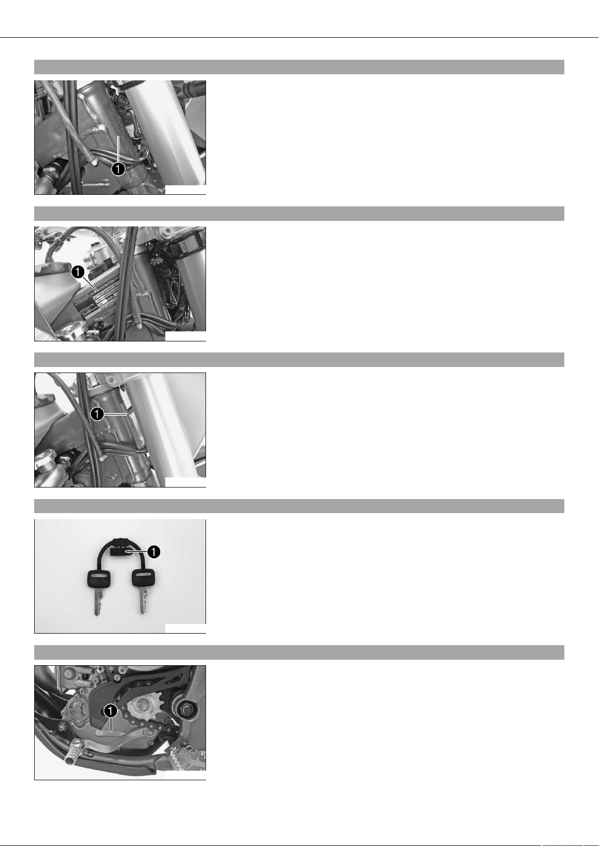
3.1Chassis number
The chassis number is stamped on the right side of the steering head.
100345-10
3.2Type label (FE EU, FE AUS)
The type label is fixed to the frame at the front right.
3.3Type label (FE USA)
3.4Key number (FE EU, FE AUS)
100458-10
The type label is fixed to the front of the steering head.
100464-10
The key number is stamped on the key strap.
3.5Engine number
500125-10
The engine number is stamped on the left side of the engine under the engine
sprocket.
100347-10
LOCATION OF SERIAL NUMBERS 8
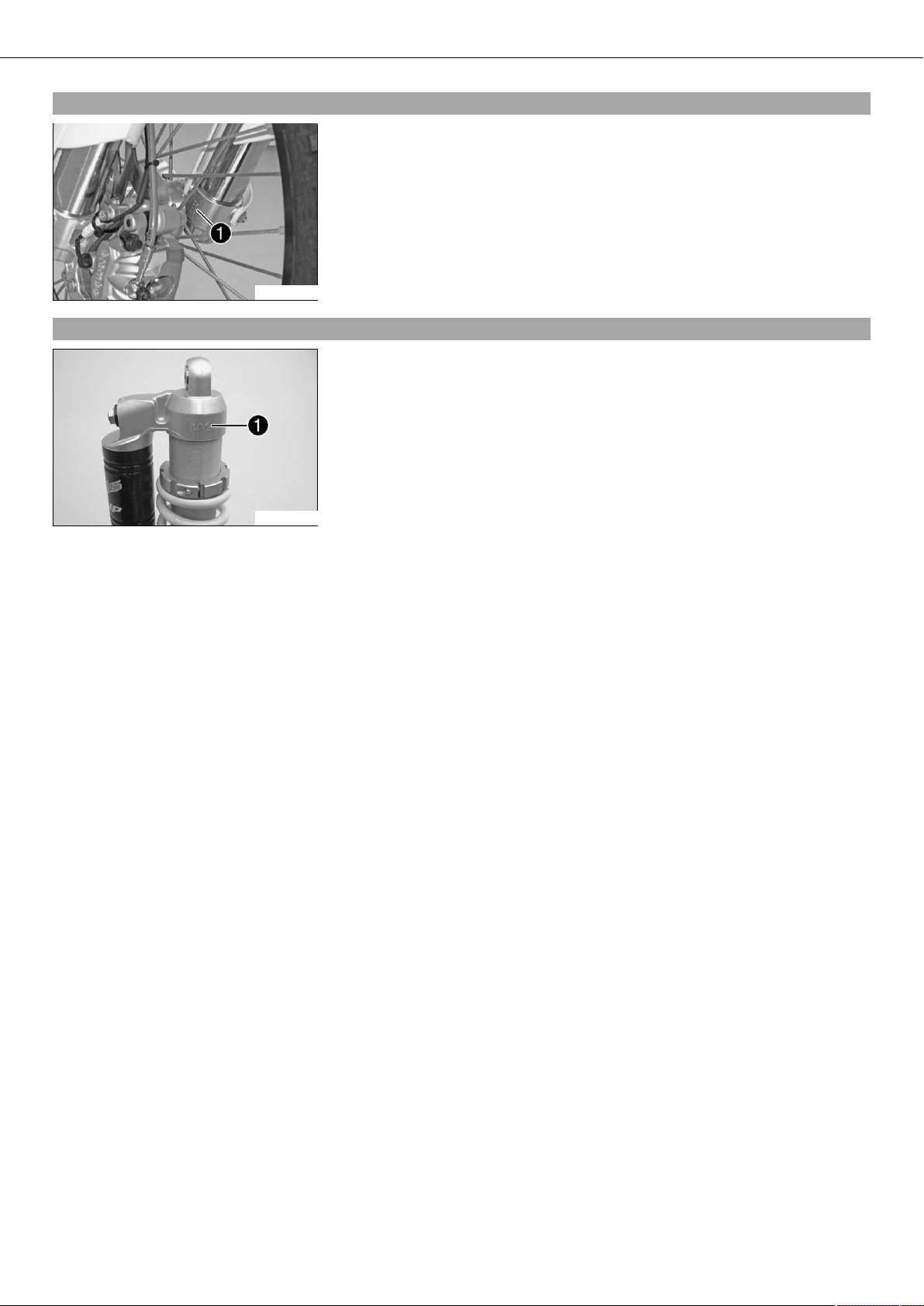
3.6Fork part number
The fork part number is stamped on the inner side of the fork stub.
100348-10
3.7Shock absorber part number
The shock absorber part number is stamped on the upper part of the shock absorber
above the adjusting ring. The shock absorber part number is not visible when the shock
absorber is installed.
100419-10
MOTORCYCLE 9
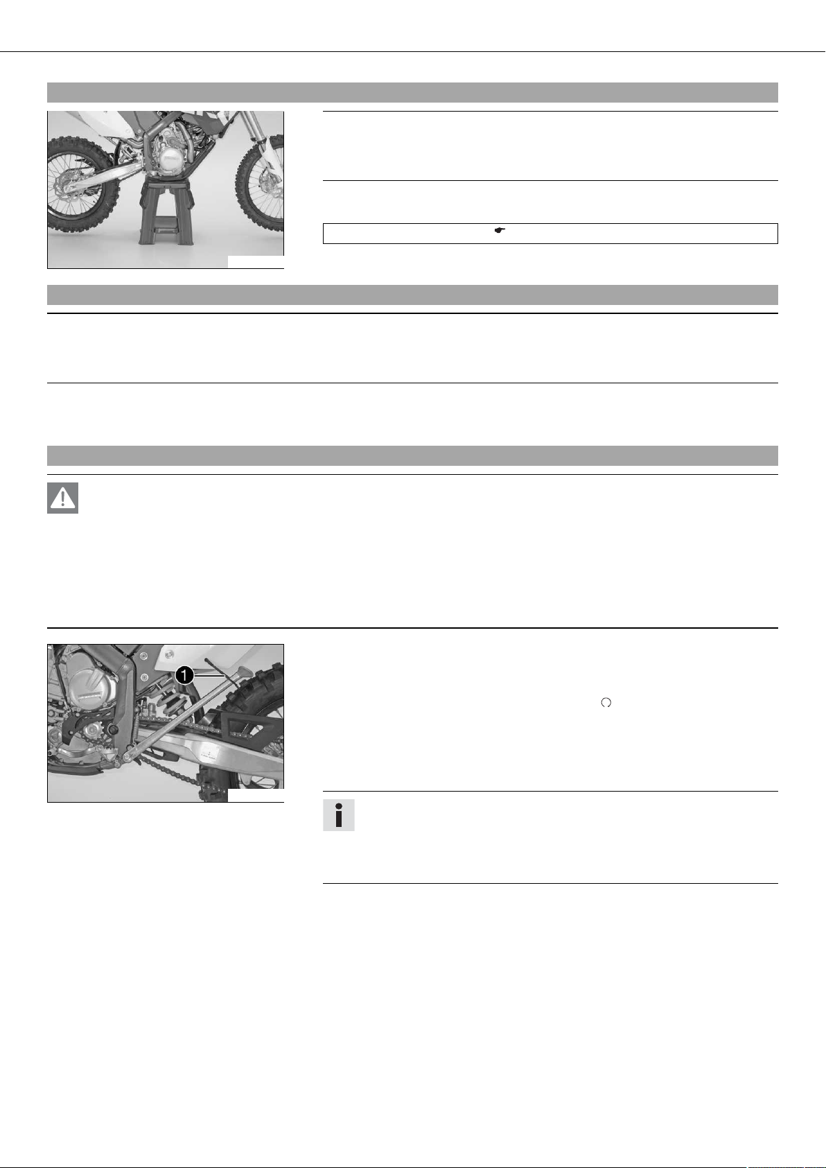
4.1Jacking up the motorcycle
Note
Danger of damage The parked vehicle can roll away or fall over.
– Always place the vehicle on a firm and even surface.
– Jack up the motorcycle underneath the engine. The wheels must no longer touch
the ground.
Work stand (81229055000) ( p. 273)
100420-10
4.2Removing the motorcycle from the work stand
– Secure the motorcycle against falling over.
Note
Danger of damage The parked vehicle can roll away or fall over.
– Always place the vehicle on a firm and even surface.
– Remove the motorcycle from the work stand.
– Remove the work stand.
4.3Starting
Danger
Danger of poisoning Exhaust gases are poisonous and can result in unconsciousness and/or death.
– When running the engine, always make sure there is sufficient ventilation, and do not start or run the engine in a closed
space without an effective exhaust extraction system.
Note
Engine failure High engine speeds in cold engines have a negative effect on the service life of the engine.
– Always warm up the engine at low engine speeds.
– Raise the motorcycle off of the stand and secure the stand with rubber band .
– Shift gear to neutral.
(FE AUS)
– Turn the emergency OFF switch to the position .
Condition
Ambient temperature: < 20 °C (< 68 °F)
– Pull the idle speed adjusting screw all the way out.
– Press the electric starter button.
100370-11
Info
Do not open the throttle to start.
Press the starter for a maximum of 5 seconds. Wait for a least 5 seconds
until trying again.
Warning lamp FI lights up briefly as a functional control when starting.

01/FORK, TRIPLE CLAMP 10
5.1Adjusting the compression damping of the fork
Info
The hydraulic compression damping determines the fork suspension behavior.
– Remove protection covers .
– Turn adjusting screws clockwise until they stop.
Info
Adjusting screws are located at the bottom end of the fork legs.
Make the same adjustment on both fork legs.
– Turn back counterclockwise by the number of clicks corresponding to the fork type.
Guideline
100377-10
Compression damping
Comfort 26 clicks
Standard 22 clicks
Sport 18 clicks
Info
Turn clockwise to increase damping, turn counterclockwise to reduce suspension damping.
– Mount protection covers .
5.2Adjusting the rebound damping of the fork
Info
The hydraulic rebound damping determines the fork suspension behavior.
– Turn adjusting screws clockwise until they stop.
Info
Adjusting screws are located at the top end of the fork legs.
Make the same adjustment on both fork legs.
– Turn back counterclockwise by the number of clicks corresponding to the fork type.
Guideline
Rebound damping
100376-10
Comfort 22 clicks
Standard 20 clicks
Sport 18 clicks
Info
Turn clockwise to increase damping, turn counterclockwise to reduce suspension damping.
5.3Adjusting the spring preload of the fork
100378-01
– Turn the adjusting screws counterclockwise until they stop.
Info
Make the same adjustment on both fork legs.
– Turn back clockwise the number of turns corresponding to the fork type.
Guideline
Spring preload - Preload Adjuster
Comfort 0 turn
Standard 2 turns
Sport 4 turns
01/FORK, TRIPLE CLAMP 11
Info
Turn clockwise to increase spring preload, turn counterclockwise to reduce
spring preload.
Adjusting the spring preload has no influence on the absorption setting of
the rebound damping.
Basically, however, you should set the rebound damping higher with a
higher spring preload.
5.4Bleeding the fork legs
– Jack up the motorcycle. ( p. 9)
– Remove bleeder screws briefly.
Any excess pressure escapes from the interior of the fork.
– Mount and tighten bleeder screws.
– Remove the motorcycle from the work stand. ( p. 9)
100379-10
5.5Cleaning the dust boots of the fork legs
100380-10
– Jack up the motorcycle. ( p. 9)
– Loosen the fork protection. ( p. 11)
– Push dust boots of both fork legs downwards.
Info
The dust boots should remove dust and coarse dirt particles from the fork
tubes. Over time, dirt can penetrate behind the dust boots. If this dirt is not
removed, the oil seals behind can start to leak.
Warning
Danger of accidents Reduced braking efficiency due to oil or grease on the
brake discs.
– Always keep the brake discs free of oil and grease, and clean them with
brake cleaner when necessary.
– Clean and oil the dust boots and inner fork tube of both fork legs.
Universal oil spray ( p. 266)
– Press the dust boots back into their normal position.
– Remove excess oil.
– Position the fork protection. ( p. 12)
– Remove the motorcycle from the work stand. ( p. 9)
5.6Loosening the fork protection
– Remove screws and take off clamp.
– Remove screws on the left fork leg. Push the fork protection downwards.
– Remove the screws on the right fork leg. Push the fork protection downwards.
100381-10
01/FORK, TRIPLE CLAMP 12
5.7Positioning the fork protection
– Position the fork protection on the left fork leg. Mount and tighten screws .
Guideline
Remaining screws, chassis M6 10 Nm (7.4 lbf ft)
– Position the brake line and cable harness. Put the clamp on, and mount and
tighten screws .
– Position the fork protection on the right fork leg. Mount and tighten the screws.
Guideline
100381-11
5.8Removing the fork legs
Remaining screws, chassis M6 10 Nm (7.4 lbf ft)
– Remove the front wheel. ( p. 65)
(FE EU, FE AUS)
– Remove the headlight mask with the headlight. ( p. 88)
(FE USA)
– Remove the start number plate. ( p. 63)
– Remove screws and take off the clamp.
5.9Installing the fork legs
300713-10
– Remove cable binders .
– Remove screws and take off the brake caliper.
– Allow the brake caliper and brake line to hang tension-free to the side.
300714-10
– Unscrew screws . Take out the left fork leg.
– Unscrew screws . Take out the right fork leg.
300715-10
– Position the fork legs.
300724-10
Info
The upper milled groove in the fork leg must be flush with the top edge of
the upper triple clamp.
Position bleeder screws toward the front.
01/FORK, TRIPLE CLAMP 13
– Tighten screws .
Guideline
Screw, top triple clamp M8 17 Nm
(12.5 lbf ft)
– Tighten screws .
Guideline
Screw, bottom triple clamp M8 12 Nm (8.9 lbf ft)
300715-11
– Position the brake caliper. Mount and tighten screws .
Guideline
Screw, front brake caliper M8 25 Nm
(18.4 lbf ft)
– Secure the cable with cable binders .
300714-11
– Position the brake line and wiring harness. Put the clamp on. Mount and tighten
screws .
– Install the front wheel. ( p. 65)
(FE EU, FE AUS)
– Install the headlight mask with the headlight. ( p. 88)
(FE USA)
– Install the start number plate. ( p. 64)
Loctite®243™
5.10Removing the fork protector
5.11Installing the fork protector
300713-11
– Remove the fork legs. ( p. 12)
– Remove screws on the left fork leg. Lift off the fork protector.
– Remove the screws on the right fork leg. Lift off the fork protector.
300716-10
– Position the fork protection on the left fork leg. Mount and tighten screws .
Guideline
Remaining screws, chassis M6 10 Nm (7.4 lbf ft)
– Position the fork protection on the right fork leg. Mount and tighten the screws.
Guideline
Remaining screws, chassis M6 10 Nm (7.4 lbf ft)
300716-10
– Install the fork legs. ( p. 12)
01/FORK, TRIPLE CLAMP 14
5.12Performing a fork service
Info
These operations are the same on both fork legs.
Condition
The fork legs have been removed.
– Disassemble the fork legs. ( p. 14)
– Disassemble the cartridge. ( p. 17)
– Check the fork legs. ( p. 19)
– Assemble the cartridge. ( p. 21)
– Assemble the fork legs. ( p. 23)
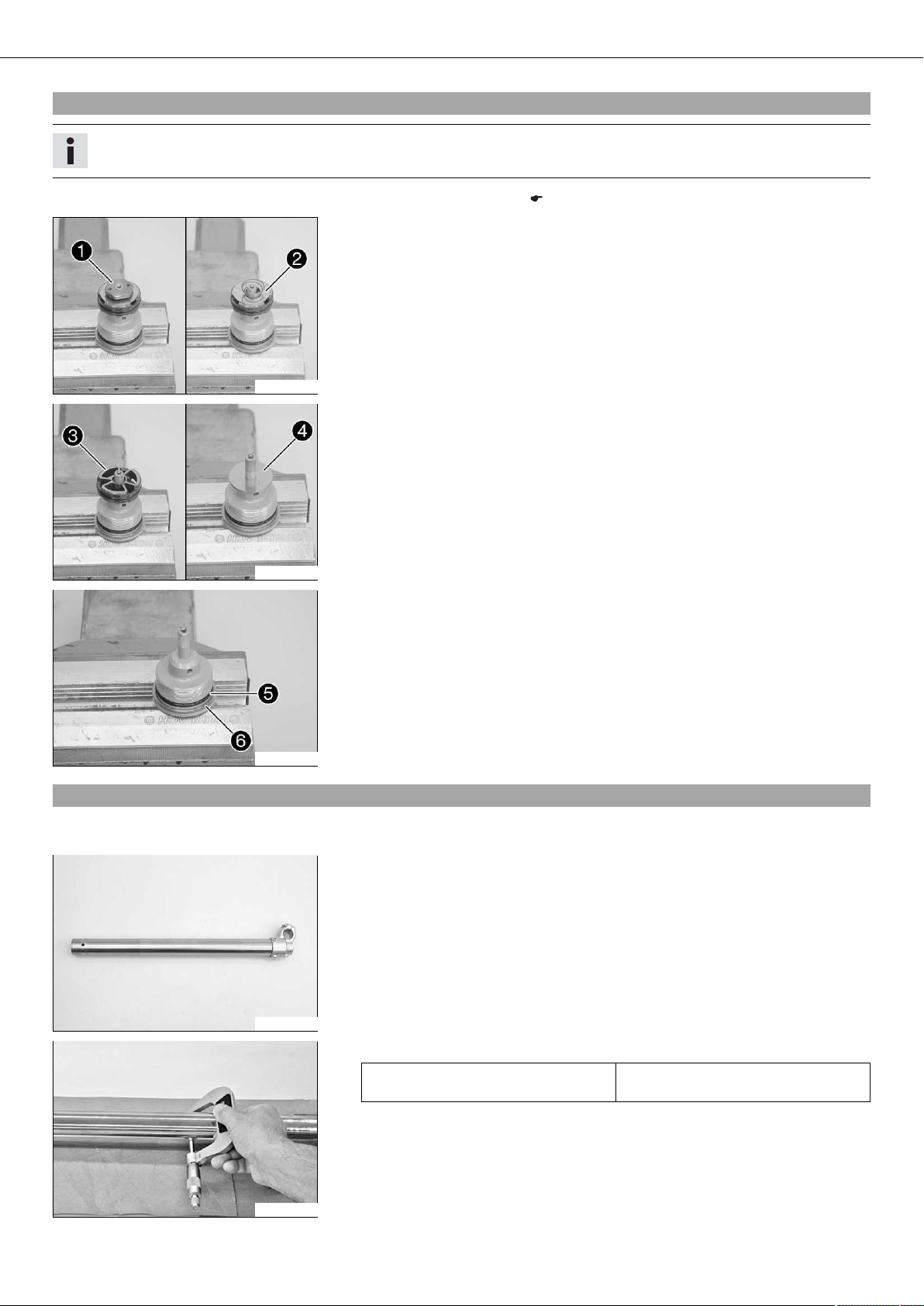
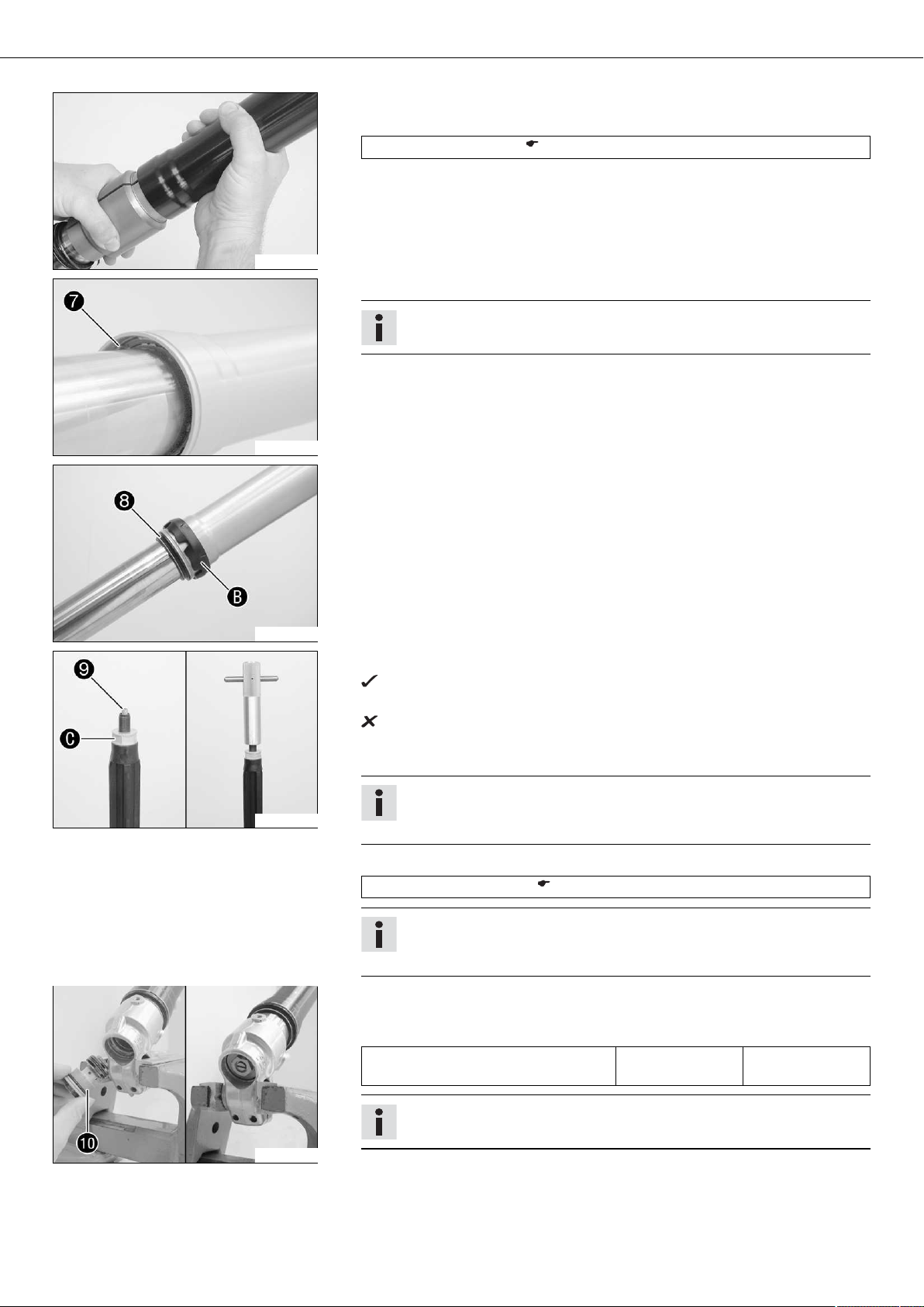
5.13Disassembling the fork legs
Info
The steps are identical for both fork legs.
200979-01
Condition
The fork legs are disassembled.
– Remove protective cover .
– Take note of the present state of the rebound damping and compression damp-
ing .
– Take note of the present state of the spring preload.
– Completely open the adjustment elements of the rebound damping and compres-
sion damping.
200736-10
– Clamp the fork leg in the area of lower triple clamp.
Clamping stand (T1403S) ( p. 277)
200643-10
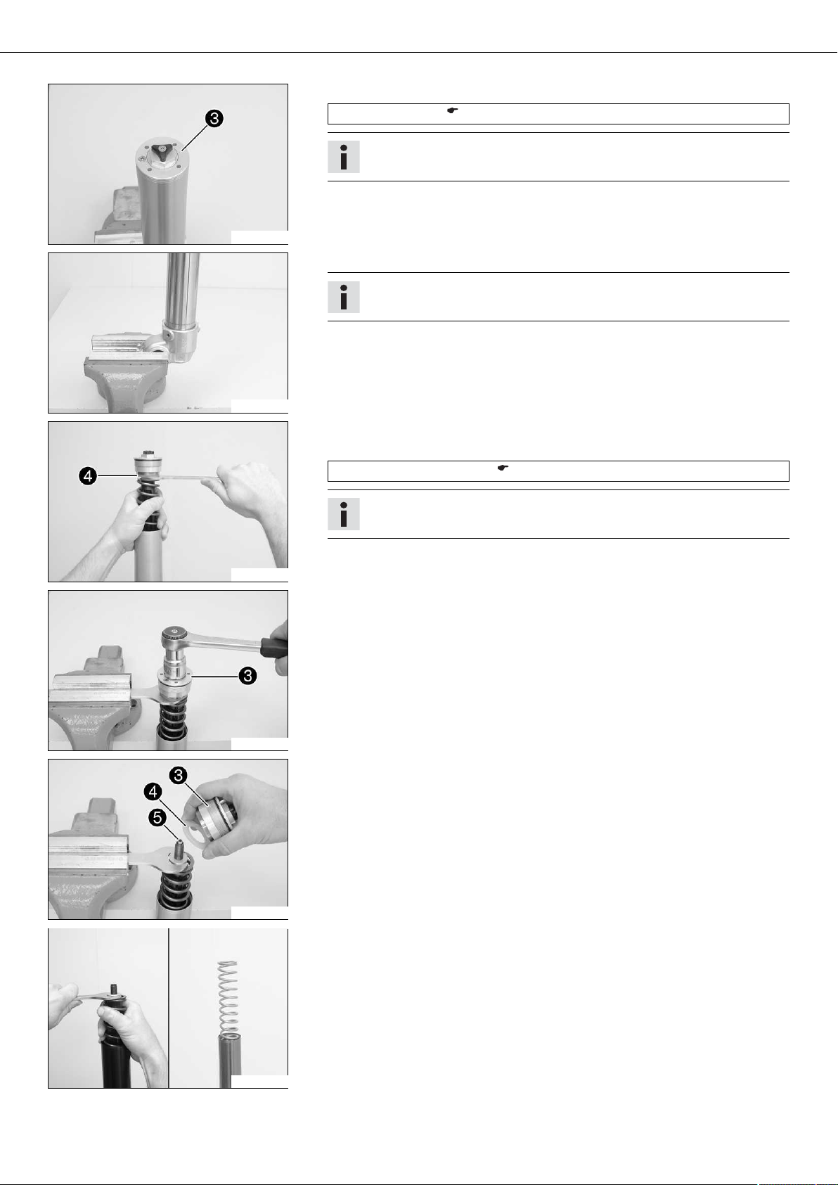
01/FORK, TRIPLE CLAMP 15
– Loosen Preload Adjuster .
Pin wrench (T103) ( p. 274)
Info
The Preload Adjuster cannot be taken off yet.
200737-10
– Take out the fork leg and clamp in with the axle clamp.
Info
Use soft jaws.
200690-10
– Push the outer tube downward.
– Pull the spring downward. Place the special tool on the hexagonal part.
200738-10
200739-10
Open-end wrench (T14032) ( p. 277)
Info
The preload spacers should be above the special tool.
– Clamp the special tool in the bench vise. Loosen Preload Adjuster .
– Remove Preload Adjuster with the preload spacers .
– Remove adjustment tube .
200740-10
200649-01
– Pull the spring downward. Remove the special tool.
– Remove the spring.
01/FORK, TRIPLE CLAMP 16
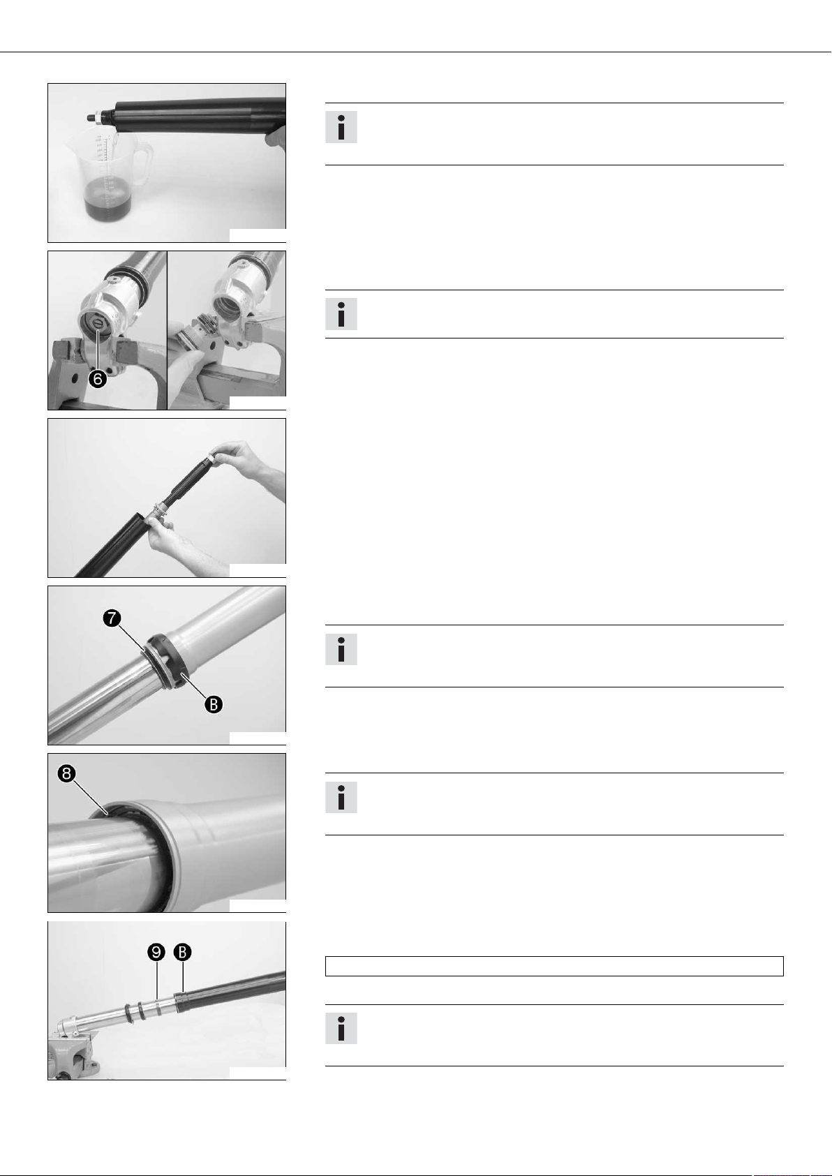
– Drain the fork oil.
Info
Pull out and push in the piston rod several times in order to pump out the
cartridge until it is empty.
200650-01
– Clamp in the fork leg with the axle clamp.
– Unscrew and remove the compression damping fitting .
Info
Place a fluid collector beneath it, as usually some oil will drain out.
200691-10
– Remove the cartridge.
200653-01
200741-10
200742-10
– Remove dust boot .
– Remove fork protector ring .
Info
Disassembly of the fork protector ring is not necessarily required for the further repair.
– Remove lock ring .
Info
The lock ring has a coarsely finished end against which the screwdriver can
be placed.
– Warm up the outer tube in the lower sliding bushing area of .
Guideline
50 °C (122 °F)
200716-10
– Jerk the outer tube out of the inner tube.
Info
The lower sliding bushing must be pulled out of its bearing seat when
doing this.
01/FORK, TRIPLE CLAMP 17
– Remove upper sliding bushing .
Info
Gently pull them apart without using any tool.
200658-01
– Take off the lower sliding bushing .
– Take off support ring .
– Take off seal ring .
– Take off lock ring .
– Take off dust boot .
– Take out the fork leg.
200659-11
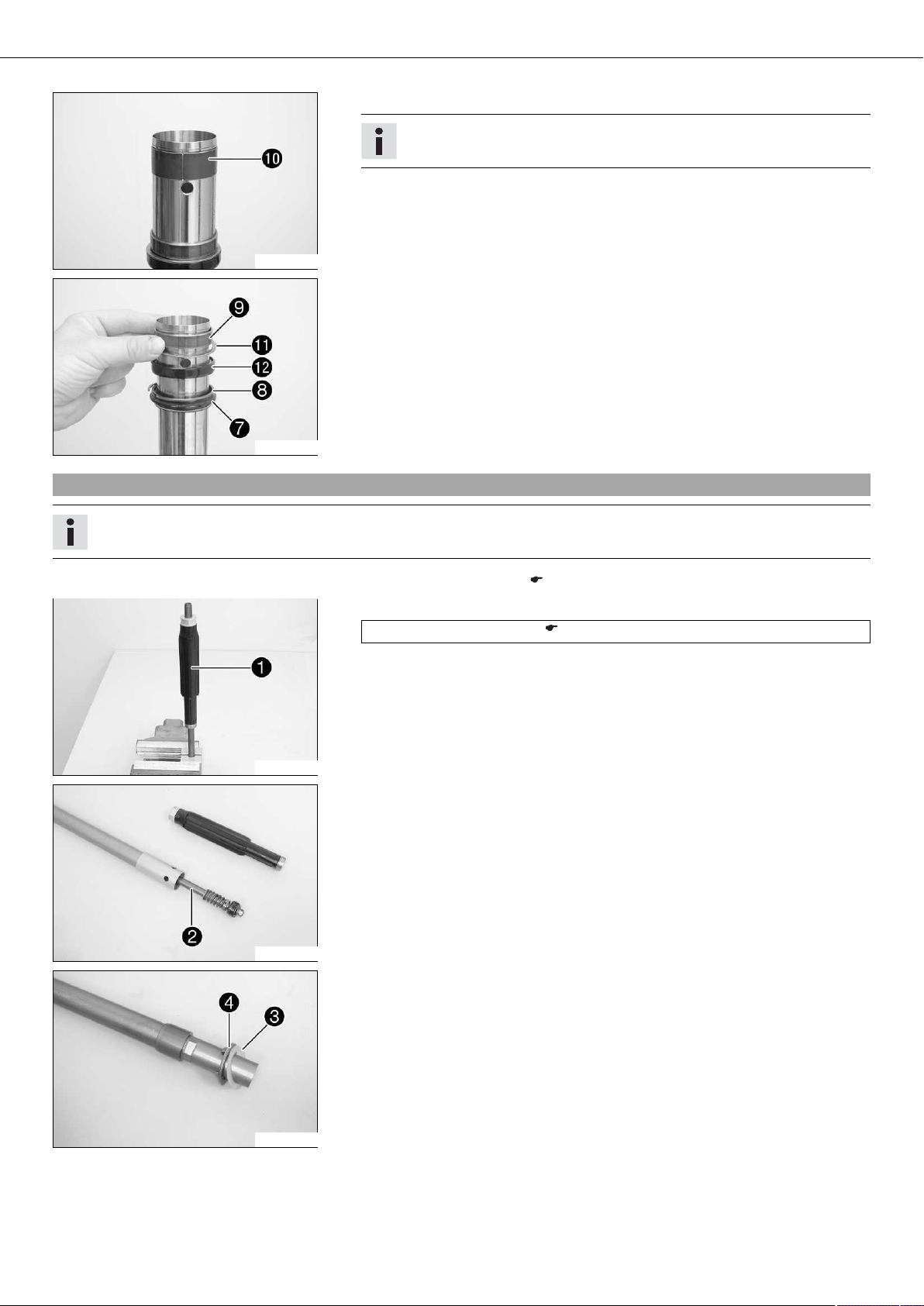
5.14Cartridge disassembly
Info
The steps are identical for both fork legs.
200746-10
200747-10
– Disassemble the fork legs. ( p. 14)
– Remove fluid barrier from the piston rod.
Clamping stand (T14016S) ( p. 276)
– Remove piston rod from the cartridge.
– Remove washer and spring seat from the cartridge.
200748-10
01/FORK, TRIPLE CLAMP 18
– Degrease the cartridge and clamp using the pecial tool.
Clamping stand (T14015S) ( p. 276)
– Warm up the cartridge in the area of .
Guideline
50 °C (122 °F)
– Unscrew and remove screwsleeve .
200749-10
200697-10
200698-10
Info
This step is unnecessary for the further disassembly.
– Degrease the piston rod.
– Clamp the piston rod with the special tool.
Clamping stand (T14016S) ( p. 276)
– Remove nut .
– Remove shim stack completely.
– Remove piston .
– Remove shim stack completely.
200699-10
200700-10
200701-10
– Remove spring .
– Remove tap rebound .
– Remove spring .
– Remove valve of the rebound damping together with the spring.
– Take out the piston rod.
01/FORK, TRIPLE CLAMP 19
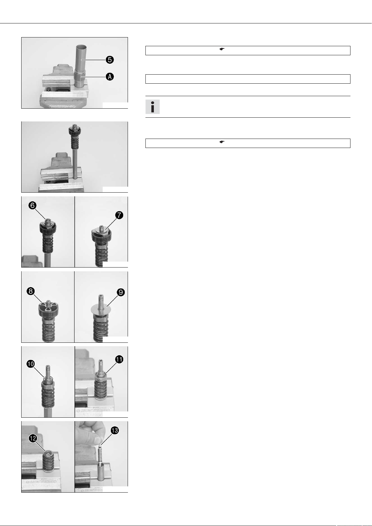
5.15Disassembling the compression damping fitting
Info
The steps are identical for both fork legs.
– Disassemble the fork legs. ( p. 14)
– Clamp the compression damping fitting in a bench vise using soft jaws.
– Remove nut .
– Remove the spring.
– Remove washer .
200702-10
– Remove piston .
– Remove shim stack .
5.16Checking the fork legs
200703-10
– Remove O-ring and seal ring from the compression damping fitting.
– Extract the compression damping fitting.
200704-10
Condition
The fork legs are disassembled.
– Check the inner tube and axle clamp for damage.
» If there is damage:
– Replace the inner tube.
200728-10
200684-10
– Measure the outside diameter at several points of the inner tube.
Outside diameter of the inner tube 47.975… 48.005 mm (1.88878…
1.88996 in)
» If the measured value is smaller than the specified value:
– Replace the inner tube.

01/FORK, TRIPLE CLAMP 20
– Measure the run-out of the inner tube.
Inner tub run-out ≤ 0.20 mm (≤ 0.0079 in)
» If the measured value is larger than the specified value:
– Replace the inner tube.
200685-10
– Check the outer tube for damage.
» If there is damage:
– Replace the outer tube.
200632-10
– Check the surface of the sliding bushing.
» If the bronze-colored layer can be seen beneath the sliding layer :
– Replace the sliding bushing.
200665-10
– Check the spring length.
200666-10
5.17Assembling the compression damping fitting
Info
The steps are identical for both fork legs.
– Clamp the compression damping fitting in a bench vise using soft jaws.
– Mount O-ring and seal ring .
– Grease the O-ring.
Guideline
Spring length with preload spacer(s) 510 mm (20.08 in)
» If the measured value is greater than the specified value:
– Reduce the thickness of the preload spacer.
» If the measured value is smaller than the specified value:
– Increase the thickness of the preload spacer.
Lubricant (T158) ( p. 265)
200704-11
01/FORK, TRIPLE CLAMP 21
– Mount shim stack .
Info
Mount the smaller shims below.
– Mount pistons with O-ring .
Info
The side with the largest inside diameter faces upward.
200705-10
200706-10
– Grease the piston O-ring.
Fork oil (SAE 5) ( p. 263)
– Mount washer .
– Mount spring with the tighter coil facing downward.
– Mount and tighten nut .
Guideline
Compression damping fitting nut M6x0.5 3 Nm (2.2 lbf ft)
Info
The washer must have freedom of movement relative to the spring force.
– Secure the nut by locking.
– Extract the compression damping fitting.
5.18Assembling the cartridge
Info
The steps are identical for both fork legs.
200715-10
200718-10
– Clamp in the piston rod.
Clamping stand (T14016S) ( p. 276)
– Mount valve of the rebound damping, with the spring and O-ring.
– Grease the O-ring.
Lubricant (T158) ( p. 265)
– Mount spring .
– Grease tap rebound O-ring.
Lubricant (T158) ( p. 265)
– Mount and tighten the tap rebound.
Guideline
Tap rebound M9x1 18 Nm
Loctite®2701
(13.3 lbf ft)
– Position spring .
– Mount shim stack .
200719-10
Info
Mount the smaller shims below.
– Press the shim stack downward against the spring force.
Info
The shim stack must be pressed downward over the collar.
– Mount piston with the piston ring.
01/FORK, TRIPLE CLAMP 22
Info
The side with the largest inside diameter faces downward.
– Mount shim stack .
Info
Align the triangular plate exactly with the piston opening.
– Mount and tighten nut .
Guideline
Tap rebound nut M6x0.5 5 Nm (3.7 lbf ft)
200720-10
200749-11
200748-11
Info
Mount the nut with the collar facing downward.
– Secure the nut by locking.
– Degrease the cartridge and clamp using the special tool.
Clamping stand (T14015S) ( p. 276)
– Mount and tighten screwsleeve .
Guideline
Screwsleeve M29x1 46 Nm
(33.9 lbf ft)
– Mount washer and spring seat .
– Push piston rod into the cartridge.
Loctite®241
200747-11
200746-11
– Screw on fluid barrier to the stop.
Info
The fluid barrier must be screwed on tightly against the stop. Do not use any
tools.
01/FORK, TRIPLE CLAMP 23
5.19Assembling the fork legs
Info
The steps are identical for both fork legs.
– Check the fork legs. ( p. 19)
– Assemble the cartridge. ( p. 21)
– Assemble the compression damping fitting. ( p. 20)
– Clamp in the inner tube with the axle clamp.
– Mount the special tool.
Protecting sleeve (T1401) ( p. 276)
– Grease and slide on dust boot .
Lubricant (T511) ( p. 266)
Info
200669-10
– Slide on lock ring .
– Grease and slide on seal ring .
Always change the dust boot, seal ring, lock ring and support ring.
Mount the sealing lip with the spring expander facing downward.
200670-10
Lubricant (T511) ( p. 266)
Info
The sealing lip should face downward and open side upward.
– Slide on support ring .
– Remove the special tool.
– Roughen, clean and grease the edges of the sliding bushings using 600 grit sand-
paper.
Fork oil (SAE 5) ( p. 263)
– Slide on lower sliding bushing .
– Mount upper sliding bushing .
Info
Gently pull them apart without using any tool.
200671-10
200723-10
– Slide on the outer tube.
– Warm up the outer tube in the lower sliding bushing area of .
Guideline
50 °C (122 °F)
– Hold the lower sliding bushing with the longer shoulder of the special tool.
Assembly tool (T1402S) ( p. 276)
– Press the outer tube all the way in.
01/FORK, TRIPLE CLAMP 24
– Position the support ring.
– Hold the seal ring with the shorter shoulder of the special tool.
Assembly tool (T1402S) ( p. 276)
– Press the outer tube all the way in.
200724-10
– Mount lock ring .
Info
The lock ring must audibly lock into place.
200742-11
– Mount dust boot .
– Mount fork protector ring .
200741-11
200725-11
– Mount adjustment tube of the rebound damping in the cartridge.
The adjustment tube extends 5 mm out from the cartridge and can be pressed
inward against the spring force.
The adjustment tube extends more than 7 mm out from the cartridge and cannot be pressed inward against the spring force.
– Screw on fluid barrier to the stop.
Info
The fluid barrier must be screwed on tightly against the stop. Do not use any
tools.
– Mount the special tool on the cartridge.
Gripping tool (T14026S1) ( p. 276)
Info
The special tool must be used in order that the adjustment tube is not
raised. Otherwise, oil will reach the piston rod.
– Push the cartridge into the inner tube.
– Mount and tighten compression damping fitting .
Guideline
Compression damping fitting M29x1 35 Nm
(25.8 lbf ft)
200726-10
Info
If the cartridge turns as well, press the piston rod slightly to the side.
01/FORK, TRIPLE CLAMP 25
– Clamp in the fork vertically.
– Fill with fork oil.
200677-10
200678-11
Fork oil per fork
leg
620 ml
(20.96 fl. oz.)
Fork oil (SAE 5) ( p. 263)
Info
Pull out and push in the piston rod several times in order to bleed air from
the cartridge.
– Remove pin of the special tool.
Gripping tool (T14026S1) ( p. 276)
– Pull out the piston rod. Mount the spring. Mount the pin again.
Guideline
Spring rate
Weight of rider: 65… 75 kg (143…
165 lb.)
Weight of rider: 75… 85 kg (165…
187 lb.)
Weight of rider: 85… 95 kg (187…
209 lb.)
– Pull the spring downward. Place the special tool on the hexagonal part.
Open-end wrench (T14032) ( p. 277)
– Remove the special tool.
4.2 N/mm (24 lb/in)
4.4 N/mm (25.1 lb/in)
4.6 N/mm (26.3 lb/in)
200679-10
200743-10
Gripping tool (T14026S1) ( p. 276)
– Clamp the special tool in the bench vise.
– Grease the threads of the piston rod.
Lubricant (T159) ( p. 266)
– Grease the upper edge of the piston rod.
Lubricant (T158) ( p. 265)
– Screw the Preload Adjuster with preload spacer onto the piston rod.
Info
The Preload Adjuster must be screwed in all the way before the piston rod
also begins to turn. In case of tight piston rod threads, it must be held to
keep it from turning. If the Preload Adjuster is not screwed in all the way,
then the rebound adjustment will not function.
– Tighten the Preload Adjuster.
Guideline
Preload Adjuster on the piston rod M12x1 25 Nm
(18.4 lbf ft)
200738-11
– Take pressure off of the special tool. Pull the spring downward and remove the spe-
cial tool.

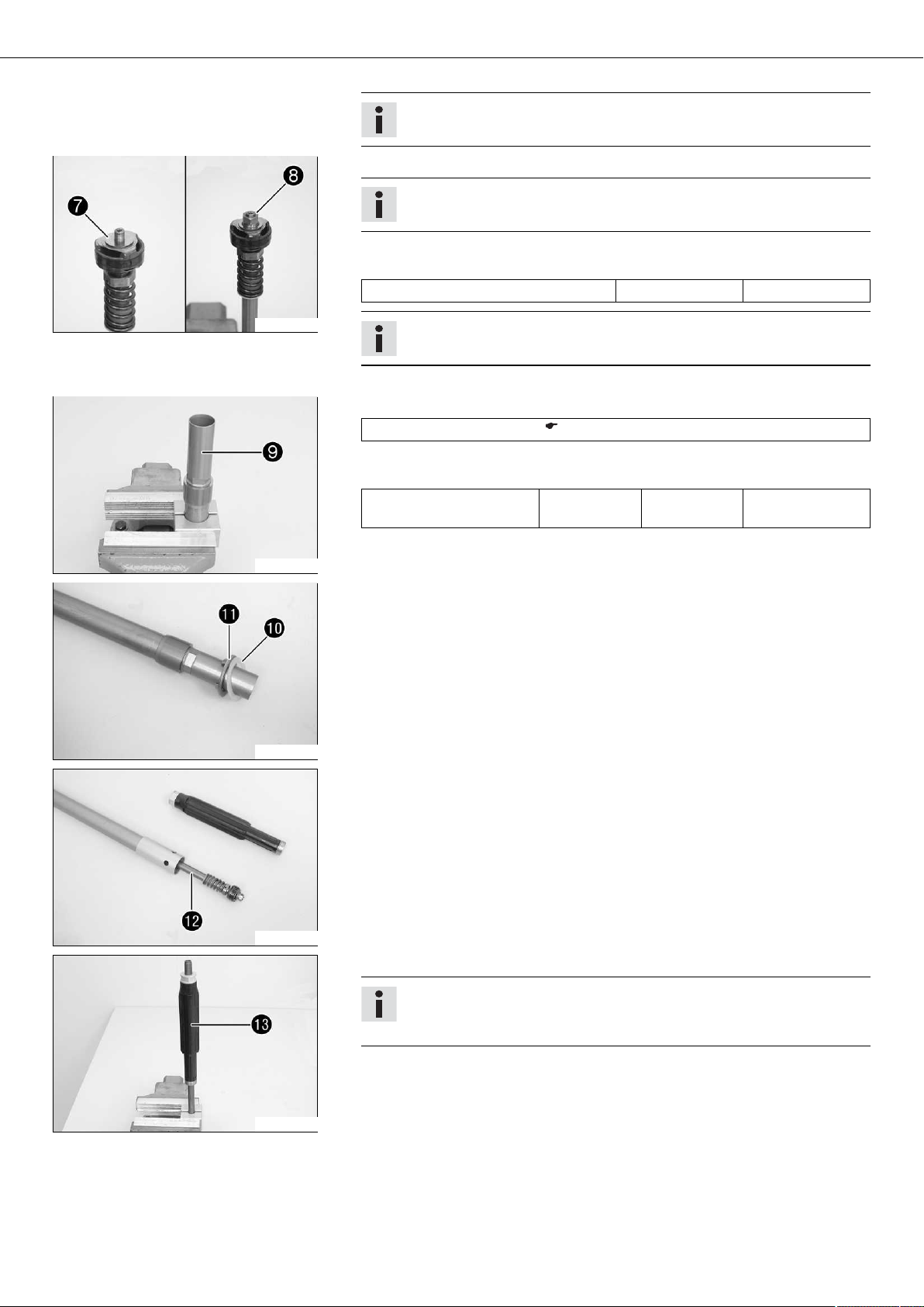
01/FORK, TRIPLE CLAMP 26
– Push the outer tube upward.
– Clamp the outer tube in the area of lower triple clamp.
Clamping stand (T1403S) ( p. 277)
– Grease the Preload Adjuster O-ring.
Lubricant (T158) ( p. 265)
– Screw on and tighten the Preload Adjuster.
200744-10
200745-10
Guideline
Preload Adjuster on the outer tube M51x1.5 50 Nm
(36.9 lbf ft)
Pin wrench (T103) ( p. 274)
Alternative 1
– Turn the compression damping adjusting screw and the adjusting screw of
the rebound stage clockwise all the way.
– Turn back counterclockwise by the number of clicks corresponding to the fork
type.
Guideline
Rebound damping
Comfort 22 clicks
Standard 20 clicks
Sport 18 clicks
Compression damping
Comfort 26 clicks
Standard 22 clicks
Sport 18 clicks
– Turn the adjusting screw of the spring preload counterclockwise all the way.
– Turn back clockwise the number of turns corresponding to the fork type.
Guideline
Spring preload - Preload Adjuster
Comfort 0 turn
Standard 2 turns
Sport 4 turns
Alternative 2
Warning
Danger of accidents Modifications to the chassis can seriously alter the
vehicle's handling characteristics.
– Extreme modifications to the adjustment of the spring elements can
cause a serious deterioration in the handling characteristics and
overload some components.
– Make settings within the recommended range only.
– Following modifications, ride slowly at first to get the feel of the new
handling characteristics.
– Set the adjusting screws to the position determined before removal.
– Mount protective cover .
01/FORK, TRIPLE CLAMP 27
5.20Greasing the steering head bearing
– Remove the lower triple clamp. ( p. 27)
– Install the lower triple clamp. ( p. 28)
800010-10
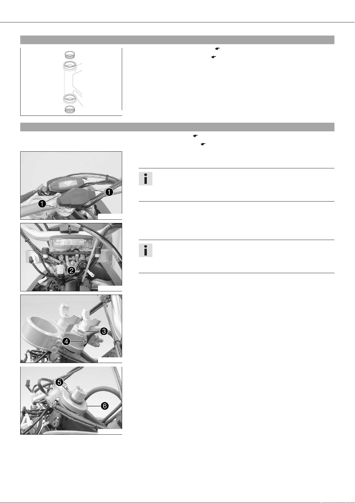
5.21Removing the lower triple clamp
– Remove the fork legs. ( p. 12)
– Remove the front fender. ( p. 63)
– Remove screws .
– Remove the handlebar and lay it to one side.
Info
Protect the motorcycle and its attachments against damage by covering
them.
Do not bend the cables and lines.
300717-10
300718-10
300719-10
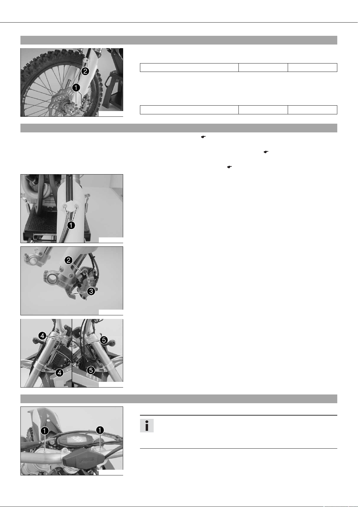
– Remove screws .
– Take off the speedometer and connector board and allow them to hang to the side.
Info
Protect the motorcycle and its attachments against damage by covering
them.
Do not bend the cables and lines.
– Remove screw .
– Remove screw .
– Take off the upper triple clamp.
– Remove O-ring .
– Remove protective ring .
– Take out the lower triple clamp with the steering stem.
– Take out the upper steering head bearing.
300720-10

01/FORK, TRIPLE CLAMP 28
5.22Installing the lower triple clamp
– Clean and grease the earings and sealing elements.
Long-life grease ( p. 265)
– Insert the lower triple clamp with the steering stem. Mount the upper steering head
bearing.
– Slide on protective ring and O-ring .
300720-11
– Position the upper triple clamp.
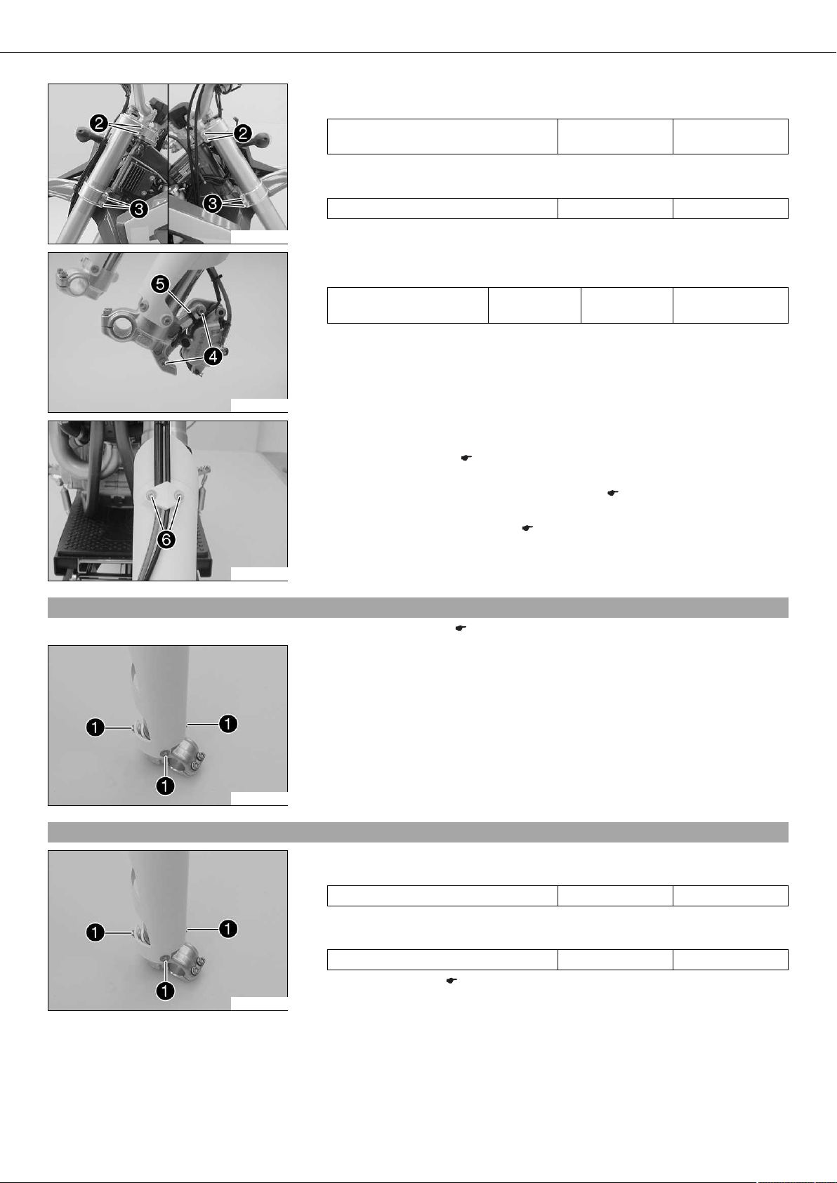
– Mount and tighten screw .
Guideline
Screw, top steering head M20x1.5 10 Nm (7.4 lbf ft)
300719-11
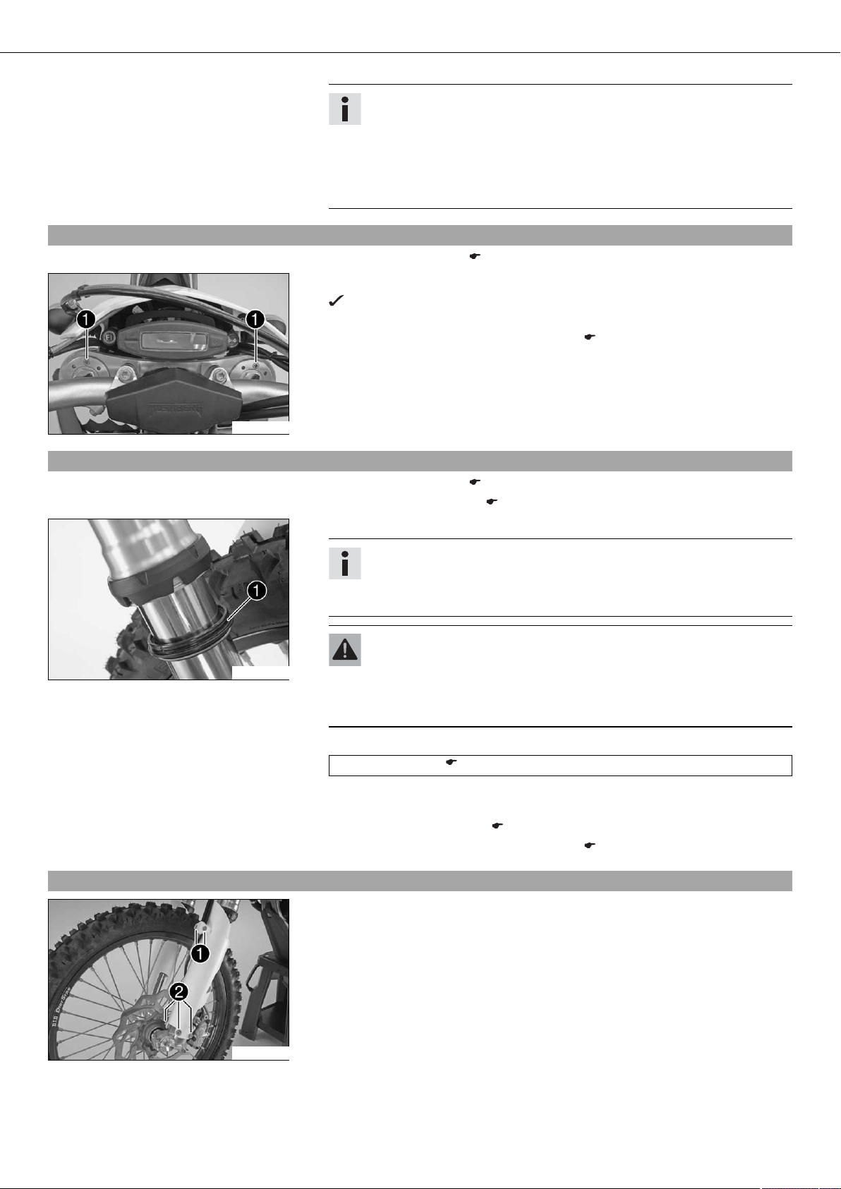
– Position the speedometer and connector board. Mount and tighten screws .
Guideline
Remaining screws, chassis M6 10 Nm (7.4 lbf ft)
300718-11
300717-11
300723-10
– Position the handlebar.
– Mount and tighten screws .
Guideline
Screw, handlebar clamp M8 20 Nm
(14.8 lbf ft)
– Install the front fender. ( p. 63)
– Install the fork legs. ( p. 12)
– Mount and tighten screw .
Guideline
Screw, top steering stem M8 17 Nm
Loctite®243™
(12.5 lbf ft)
– Check wiring harness, control cables, brake and clutch lines for freedom of move-
ment and routing.
– Check the play of the steering head bearing. ( p. 29)
 Loading...