

HUSABERG FE 450 EU (2014), FE 450 AUS (2014), FE 501 EU (2014), FE 501 AUS (2014), FE 501 USA (2014) Owner's Manual

OWNER'S MANUAL
FE 450 EU
FE 450 AUS
FE 501 EU
FE 501 AUS
FE 501 USA
2014
Art. no. 3802040en


DEAR HUSABERG CUSTOMER 1
DEARHUSABERG CUSTOMER
Congratulations on your decision to purchase a HUSABERG motorcycle. You are now the owner of a state-of-the-art sports motorcycle
that will give you enormous pleasure if you service and maintain it accordingly.
We wish you a lot of enjoyment in riding this vehicle.
Please enter the serial number of your vehicle below.
Chassis number ( p. 12) Stamp of dealer
Engine number ( p. 12)
Key number (FE EU, FE AUS) ( p. 12)
The Owner's Manual contained the latest information for this model at the time of going to print. Slight deviations resulting from continuing development and design of the motorcycles can, however, not be completely excluded.
All specifications are non-binding. HUSABERG, a division of KTM Sportmotorcycle AG (referred to below as HUSABERG) specifically
reserves the right to modify or delete technical specifications, prices, colors, forms, materials, services, designs, equipment, etc.,
without prior notice and without specifying reasons, to adapt these to local conditions, as well as to stop production of a particular
model without prior notice. HUSABERG accepts no liability for delivery options, deviations from illustrations and descriptions or misprints and other errors. The models portrayed partly contain special equipment that does not belong to the regular scope of delivery.
© 2013 KTM-Sportmotorcycle AG / Division HUSABERG, Mattighofen Austria
All rights reserved
Reproduction, even in part, as well as copying of all kinds, is permitted only with the express written permission of the copyright
owner.
ISO 9001(12 100 6061)
Within the meaning of the international quality management standard ISO 9001, HUSABERG uses quality assurance
processes that lead to the maximum possible quality of the products.
Issued by: TÜV Management Service
KTM-Sportmotorcycle AG / Division HUSABERG
5230 Mattighofen, Austria

TABLE OF CONTENTS 2
TABLEOF CONTENTS
1 MEANS OF REPRESENTATION ..................................... 5
1.1 Symbols used ................................................... 5
1.2 Formats used.................................................... 5
2 SAFETY ADVICE........................................................... 6
2.1 Use definition - intended use ............................. 6
2.2 Safety advice.................................................... 6
2.3 Degrees of risk and symbols ............................... 6
2.4 Tampering warning............................................ 6
2.5 Safe operation .................................................. 7
2.6 Protective clothing ............................................ 7
2.7 Work rules........................................................ 7
2.8 Environment..................................................... 7
2.9 Owner's Manual ................................................ 8
3 IMPORTANT INFORMATION ......................................... 9
3.1 Manufacturer and implied warranty..................... 9
3.2 Operating and auxiliary substances ..................... 9
3.3 Spare parts, accessories .................................... 9
3.4 Service ............................................................ 9
3.5 Figures ............................................................ 9
3.6 Customer service............................................... 9
4 VIEW OF VEHICLE ..................................................... 10
4.1 View of vehicle, front left (example).................. 10
4.2 View of vehicle, rear right (example) ................. 11
5 SERIAL NUMBERS .................................................... 12
5.1 Chassis number .............................................. 12
5.2 Type label (FE EU, FE AUS)............................. 12
5.3 Key number (FE EU, FE AUS).......................... 12
5.4 Engine number ............................................... 12
5.5 Fork part number ............................................ 12
5.6 Shock absorber part number ............................ 13
6 CONTROLS................................................................ 14
6.1 Clutch lever.................................................... 14
6.2 Hand brake lever............................................. 14
6.3 Throttle grip ................................................... 14
6.4 Kill switch (FE EU, FE AUS) ............................ 14
6.5 Kill switch (FE 501 USA) ................................ 14
6.6 Horn button (FE EU, FE AUS).......................... 15
6.7 Light switch (FE EU, FE AUS).......................... 15
6.8 Light switch (FE 501 USA) .............................. 15
6.9 Turn signal switch (FE EU, FE AUS) ................. 15
6.10 Emergency OFF switch (FE AUS)...................... 15
6.11 Electric starter button (FE EU, FE 501 USA) ..... 16
6.12 Electric starter button (FE AUS) ....................... 16
6.13 Overview of indicator lamps (FE EU, FE AUS).... 16
6.14 Overview of indicator lamps (FE 501 USA) ........ 16
6.15 Opening filler cap ........................................... 16
6.16 Closing filler cap............................................. 17
6.17 Idle speed adjusting screw ............................... 17
6.18 Shift lever ...................................................... 18
6.19 Foot brake lever.............................................. 18
6.20 Side stand...................................................... 18
6.21 Steering lock (FE EU, FE AUS)......................... 19
6.22 Locking the steering (FE EU, FE AUS) .............. 19
6.23 Unlocking the steering (FE EU, FE AUS) ........... 19
7 SPEEDOMETER ......................................................... 20
7.1 Overview ........................................................ 20
7.2 Activation....................................................... 20
7.3 Message on the speedometer ........................... 20
7.4 Setting the speedometer.................................. 20
7.5 Setting kilometers or miles............................... 21
7.6 Setting the clock............................................. 22
7.7 Setting the service display ............................... 22
7.8 Speed, time, and DST distance 1 ..................... 23
7.9 Speed, time, and DST2 distance 2 ................... 23
7.10 AVG average speed, ART operating hours, and
ODO total distance covered .............................. 23
8 PREPARING FOR USE................................................ 24
8.1 Advice on first use .......................................... 24
8.2 Running-in the engine ..................................... 25
8.3 Preparing the vehicle for difficult riding
conditions ...................................................... 25
8.4 Preparing for rides on dry sand......................... 26
8.5 Preparing for rides on wet sand ........................ 26
8.6 Preparing for rides on wet and muddy
surfaces ......................................................... 27
8.7 Preparing for rides at high temperature and
slow speed ..................................................... 27
8.8 Preparing for rides at low temperature or in
snow.............................................................. 27
9 RIDING INSTRUCTIONS............................................. 28
9.1 Checks and maintenance work when preparing
for use ........................................................... 28
9.2 Starting.......................................................... 28
9.3 Starting off..................................................... 29
9.4 Shifting, riding ............................................... 29
9.5 Braking.......................................................... 29
9.6 Stopping, parking............................................ 30
9.7 Transport ....................................................... 30
9.8 Refueling ....................................................... 31
10 SERVICE SCHEDULE ................................................. 32
10.1 Service schedule............................................. 32
10.2 Service work (as additional order) ..................... 33
11 TUNING THE CHASSIS .............................................. 34
11.1 Checking the basic chassis setting with the
rider's weight.................................................. 34
11.2 Compression damping of shock absorber ........... 34
11.3 Adjusting the low-speed compression damping
of the shock absorber ...................................... 34
11.4 Adjusting the high-speed compression
damping of the shock absorber ......................... 35
11.5 Adjusting the rebound damping of the shock
absorber......................................................... 35
11.6 Measuring rear wheel sag unloaded................... 36
11.7 Checking the static sag of the shock absorber .... 36
11.8 Checking the riding sag of the shock absorber.... 36
11.9 Adjusting the spring preload of the shock
absorber x.................................................... 37
11.10 Adjusting the riding sag x.............................. 37
11.11 Checking basic setting of fork .......................... 38
11.12 Adjusting the compression damping of the
fork ............................................................... 38
11.13 Adjusting the rebound damping of the fork ........ 38
11.14 Handlebar position.......................................... 39
11.15 Adjusting the handlebar position x ................. 39
12 SERVICE WORK ON THE CHASSIS.............................. 41
12.1 Raising the motorcycle with a lift stand............. 41
12.2 Removing the motorcycle from the lift stand...... 41
12.3 Bleeding fork legs ........................................... 41
12.4 Cleaning the dust boots of the fork legs............. 41
12.5 Loosening the fork protector............................. 42
12.6 Positioning the fork protection.......................... 42
12.7 Removing the fork legs .................................... 42
12.8 Installing the fork legs x................................ 43
12.9 Removing the fork protector x ........................ 43

TABLE OF CONTENTS 3
12.10 Installing the fork protector x......................... 44
12.11 Removing the lower triple clamp x.................. 44
12.12 Installing the lower triple clamp x .................. 45
12.13 Checking the steering head bearing play............ 46
12.14 Adjusting the play of the steering head
bearing x ..................................................... 47
12.15 Lubricating the steering head bearing x .......... 47
12.16 Removing the front fender ............................... 48
12.17 Installing the front fender ................................ 48
12.18 Removing the shock absorber x...................... 48
12.19 Installing the shock absorber x....................... 49
12.20 Removing the seat .......................................... 49
12.21 Mounting the seat........................................... 49
12.22 Removing the air filter box lid .......................... 50
12.23 Installing the air filter box lid ........................... 50
12.24 Removing the air filter x................................ 50
12.25 Installing the air filter x................................. 50
12.26 Cleaning the air filter and air filter box x......... 51
12.27 Sealing the air filter box x.............................. 51
12.28 Removing the main silencer ............................. 52
12.29 Installing the main silencer.............................. 52
12.30 Changing the glass fiber yarn filling of the
main silencer x............................................. 52
12.31 Removing the right side cover .......................... 53
12.32 Installing the right side cover ........................... 54
12.33 Removing the fuel tank x............................... 54
12.34 Installing the fuel tank x................................ 55
12.35 Checking for chain dirt accumulation................ 56
12.36 Cleaning the chain .......................................... 56
12.37 Checking the chain tension.............................. 57
12.38 Adjusting the chain tension.............................. 57
12.39 Checking the chain, rear sprocket, engine
sprocket and chain guide ................................. 58
12.40 Checking the frame x.................................... 60
12.41 Checking the swingarm x............................... 60
12.42 Checking the routing of the throttle cable .......... 60
12.43 Checking the rubber grip ................................. 61
12.44 Additionally securing the rubber grip................. 61
12.45 Adjusting the basic position of the clutch
lever .............................................................. 61
12.46 Checking/rectifying the fluid level of the
hydraulic clutch.............................................. 61
12.47 Changing the hydraulic clutch fluid x.............. 62
12.48 Removing the engine guard.............................. 62
12.49 Installing the engine guard .............................. 62
13 BRAKE SYSTEM ........................................................ 63
13.1 Checking free travel of hand brake lever ............ 63
13.2 Adjusting free travel of hand brake lever
(FE EU, FE AUS) ............................................ 63
13.3 Adjusting the basic position of the hand brake
lever (FE 501 USA)......................................... 63
13.4 Checking the brake discs ................................. 64
13.5 Checking the front brake fluid level .................. 64
13.6 Adding front brake fluid x.............................. 64
13.7 Checking the front brake linings ....................... 65
13.8 Changing the front brake linings x.................. 66
13.9 Checking the free travel of foot brake lever ........ 67
13.10 Adjusting the basic position of the foot brake
lever x ......................................................... 67
13.11 Checking the rear brake fluid level.................... 68
13.12 Adding rear brake fluid x ............................... 68
13.13 Checking the rear brake linings ........................ 69
13.14 Changing the rear brake linings x ................... 70
14 WHEELS, TIRES ........................................................ 72
14.1 Removing the front wheel x ........................... 72
14.2 Installing the front wheel x ............................ 72
14.3 Removing the rear wheel x............................. 73
14.4 Installing the rear wheel x.............................. 73
14.5 Checking the tire condition .............................. 74
14.6 Checking the tire air pressure........................... 75
14.7 Checking spoke tension ................................... 75
15 ELECTRICAL SYSTEM ................................................ 77
15.1 Removing the battery x.................................. 77
15.2 Installing the battery x .................................. 77
15.3 Charging the battery x ................................... 78
15.4 Changing the main fuse................................... 79
15.5 Changing the fuses of individual power
consumers...................................................... 79
15.6 Removing the headlight mask with the
headlight........................................................ 80
15.7 Installing the headlight mask with the
headlight........................................................ 80
15.8 Changing the headlight bulb ............................ 81
15.9 Changing the turn signal bulb (FE EU,
FE AUS)......................................................... 81
15.10 Checking the headlight setting ......................... 82
15.11 Adjusting the headlight range........................... 82
15.12 Changing the speedometer battery.................... 83
16 COOLING SYSTEM ..................................................... 84
16.1 Cooling system ............................................... 84
16.2 Checking the antifreeze and coolant level.......... 84
16.3 Checking the coolant level ............................... 85
16.4 Draining the coolant x ................................... 85
16.5 Refilling coolant x......................................... 86
17 TUNING THE ENGINE................................................ 87
17.1 Checking the play in the throttle cable .............. 87
17.2 Adjusting the play in the throttle cable x......... 87
17.3 Adjusting the idle speed x ............................. 88
17.4 Checking the basic position of the shift lever ..... 88
17.5 Adjusting the basic position of the shift
lever x ......................................................... 88
18 SERVICE WORK ON THE ENGINE ............................... 89
18.1 Changing the fuel screen x ............................ 89
18.2 Checking the engine oil level............................ 89
18.3 Changing the engine oil and oil filter, cleaning
the oil screens x ........................................... 90
18.4 Adding engine oil............................................ 92
19 CLEANING, CARE ...................................................... 93
19.1 Cleaning the motorcycle .................................. 93
19.2 Checks and maintenance steps for winter
operation........................................................ 94
20 STORAGE.................................................................. 95
20.1 Storage.......................................................... 95
20.2 Preparing for use after storage.......................... 95
21 TROUBLESHOOTING ................................................. 96
22 BLINK CODE ............................................................. 98
23 TECHNICAL DATA.................................................... 100
23.1 Engine......................................................... 100
23.2 Engine tightening torques .............................. 100
23.3 Capacities.................................................... 102
23.3.1 Engine oil ................................................ 102
23.3.2 Coolant.................................................... 102
23.3.3 Fuel ........................................................ 102
23.4 Chassis........................................................ 102

TABLE OF CONTENTS 4
23.5 Electrical system........................................... 103
23.6 Tires............................................................ 103
23.7 Fork............................................................. 103
23.8 Shock absorber ............................................. 104
23.9 Chassis tightening torques ............................. 104
24 SUBSTANCES ......................................................... 106
25 AUXILIARY SUBSTANCES ........................................ 108
26 STANDARDS ........................................................... 110
INDEX ............................................................................ 111
1 MEANS OF REPRESENTATION 5
1.1 Symbols used
The meaning of specific symbols is described below.
Identifies an expected reaction (e.g. of a work step or a function).
Identifies an unexpected reaction (e.g. of a work step or a function).
All work marked with this symbol requires specialist knowledge and technical understanding. In the interest of
your own safety, have these jobs performed by an authorized HUSABERG workshop. There, your motorcycle will
be optimally cared for by specially trained experts using the specialist tools required.
Identifies a page reference (more information is provided on the specified page).
1.2 Formats used
The typographical formats used in this document are explained below.
Specific name Identifies a proprietary name.
®
Name
Brand™ Identifies a brand available on the open market.
Identifies a protected name.

2 SAFETY ADVICE 6
2.1 Use definition - intended use
(FE EU, FE AUS)
HUSABERG sport motorcycles are designed and built to withstand the normal stresses and strains of competitive use. The motorcycles comply with currently valid regulations and categories of the top international motorsport organizations.
Info
The vehicle should only be used by trained persons. The motorcycle is authorized for public road traffic in the homologous
(reduced) version only.
In the derestricted version, the motorcycle must be used only on closed off properties remote from public road traffic.
This motorcycle is designed for use in offroad endurance competition and not primarily for use in motocross.
(FE 501 USA)
HUSABERG sport motorcycles are designed and built to withstand the normal stresses and strains of competitive use. The motorcycles comply with currently valid regulations and categories of the top international motorsport organizations.
Info
The motorcycle may only be used in closed off areas remote from public road traffic.
This motorcycle is designed for use in offroad endurance competition and not primarily for use in motocross.
2.2 Safety advice
A number of safety instructions need to be followed to operate the vehicle safely. Therefore, read this manual carefully. The safety
instructions are highlighted in the text and are referred to at the relevant passages.
Info
The vehicle has various information and warning labels at prominent locations. Do not remove information/warning labels. If
they are missing, you or others may not recognize dangers and may therefore be injured.
2.3 Degrees of risk and symbols
Danger
Identifies a danger that will immediately and invariably lead to fatal or serious permanent injury if the appropriate measures
are not taken.
Warning
Identifies a danger that is likely to lead to fatal or serious injury if the appropriate measures are not taken.
Caution
Identifies a danger that may lead to minor injuries if the appropriate measures are not taken.
Note
Identifies a danger that will lead to considerable machine and material damage if the appropriate measures are not taken.
Warning
Identifies a danger that will lead to environmental damage if the appropriate measures are not taken.
2.4 Tampering warning
Tampering with the noise control system is prohibited. Federal law prohibits the following acts or the causing thereof:
1 The removal or rendering inoperative by any person other than for purposes of maintenance, repair, or replacement, of any device
or element of design incorporated into any new vehicle for the purpose of noise control prior to its sale or delivery to the ultimate
purchaser or while it is in use, or
2 the use of the vehicle after such device or element of design has been removed or rendered inoperative by any person.
Among those acts presumed to constitute tampering are the acts listed below:
2 SAFETY ADVICE 7
1 Removal or puncturing of the main silencer, baffles, header pipes or any other components which conduct exhaust gases.
2 Removal or puncturing of parts of the intake system.
3 Lack of proper maintenance.
4 Replacing moving part of the vehicle, or parts of the exhaust or intake system, with parts other than those specified by the manu-
facturer.
2.5 Safe operation
Danger
Danger of accidents Danger arising from the rider's judgement being impaired.
– Do not operate the vehicle while under the influence of alcohol, drugs and certain medications or physically or mentally
impaired.
Danger
Danger of poisoning Exhaust gases are toxic and inhaling them may result in unconsciousness and/or death.
– When running the engine, always make sure there is sufficient ventilation, and do not start or run the engine in an enclosed
space without an effective exhaust extraction system.
Warning
Danger of burns Some vehicle components become very hot when the vehicle is operated.
– Do not touch hot components such as exhaust system, radiator, engine, shock absorber, and the brake system. Allow these
components to cool down before starting work on them.
Only operate the vehicle when it is in perfect technical condition, in accordance with its intended use, and in a safe and environmentally compatible manner.
An appropriate driver's license is needed to ride the vehicle on public roads.
Have malfunctions that impair safety promptly eliminated by an authorized HUSABERG workshop.
Adhere to the information and warning labels on the vehicle.
2.6 Protective clothing
Warning
Risk of injury Missing or poor protective clothing presents an increased safety risk.
– Wear protective clothing (helmet, boots, gloves, pants and jacket with protectors) every time you ride the vehicle. Always
wear protective clothing that is in good condition and meets the legal requirements.
In the interest of your own safety, HUSABERG recommends that you only operate the vehicle while wearing protective clothing.
2.7 Work rules
Special tools are necessary for certain tasks. The tools are not contained in the vehicle but can be ordered under the number in parentheses. E.g.: bearing puller (15112017000)
During assembly, non-reusable parts (e.g. self-locking screws and nuts, seals and seal rings, O-rings, pins, lock washers) must be
replaced by new parts.
In some instances, a thread locker (e.g. Loctite®) is required. The manufacturer instructions for use must be followed.
After disassembly, clean the parts that are to be reused and check them for damage and wear. Change damaged or worn parts.
After you complete the repair or service work, check the operating safety of the vehicle.
2.8 Environment
If you use your motorcycle responsibly, you can ensure that problems and conflicts do not occur. To protect the future of the motorcycle sport, make sure that you use your motorcycle legally, display environmental consciousness, and respect the rights of others.
When disposing of used oil, other operating and auxiliary fluids, and used components, comply with the laws and regulations of the
respective country.
Because motorcycles are not subject to the EU regulations governing the disposal of used vehicles, there are no legal regulations that
pertain to the disposal of an end-of-life motorcycle. Your authorized HUSABERG dealer will be glad to advise you.

2 SAFETY ADVICE 8
2.9 Owner's Manual
It is important that you read this Owner's Manual carefully and completely before making your first trip. The Owner's Manual contains
useful information and many tips on how to operate, handle, and maintain your motorcycle. Only then will you find out how to customize the vehicle ideally for your own use and how you can protect yourself from injury.
Keep the Owner's Manual in an accessible place to enable you to refer to it as needed.
If you would like to know more about the vehicle or have questions on the material you read, please contact an authorized HUSABERG
dealer.
The Owner's Manual is an important component of the vehicle and should be handed over to the new owner if the vehicle is sold.

3 IMPORTANT INFORMATION 9
3.1 Manufacturer and implied warranty
The work prescribed in the service schedule must be carried out by an authorized HUSABERG workshop only and confirmed in the
customer's service booklet and in the HUSABERG dealer.net; otherwise, all manufacturer warranty claims shall be void. No manufacturer warranty claims can be considered for damage resulting from manipulations and/or alterations to the vehicle.
Additional information on the manufacturer or implied warranty and the procedures involved can be found in the service booklet.
3.2 Operating and auxiliary substances
Warning
Environmental hazard Improper handling of fuel is a danger to the environment.
– Do not allow fuel to get into the ground water, the ground, or the sewage system.
Use operating and auxiliary substances (such as fuel and lubricants) as specified in the Owner's Manual.
3.3 Spare parts, accessories
For your own safety, only use spare parts and accessory products that are approved and/or recommended by HUSABERG and have
them installed by an authorized HUSABERG workshop. HUSABERG accepts no liability for other products and any resulting damage
or loss.
Certain spare parts and accessory products are specified in parentheses in the descriptions. Your HUSABERG dealer will be glad to
advise you.
The current HUSABERG Pure Tech parts for your vehicle can be found on the HUSABERG website.
International HUSABERG website: www.husaberg.com
3.4 Service
A prerequisite for perfect operation and prevention of premature wear is that the service, care, and tuning work on the engine and
chassis is properly carried out as described in the Owner's Manual. Incorrect adjustment and tuning of the engine and chassis can
lead to damage and breakage of components.
Use of the vehicle under difficult conditions, such as on sand or on wet and muddy surfaces, can lead to considerably more rapid wear
of components such as the drive train, brake system, or suspension components. For this reason, it may be necessary to inspect or
replace parts before the next scheduled service.
It is imperative that you adhere to the stipulated run-in times and service intervals. If you observe these exactly, you will ensure a
much longer service life for your motorcycle.
3.5 Figures
The figures contained in the manual may depict special equipment.
In the interest of clarity, some components may be shown disassembled or may not be shown at all. It is not always necessary to disassemble the component to perform the activity in question. Please follow the instructions in the text.
3.6 Customer service
Your authorized HUSABERG dealer will be happy to answer any questions you may have on your vehicle and HUSABERG.
A list of authorized HUSABERG dealers can be found on the HUSABERG website.
International HUSABERG website: www.husaberg.com

4 VIEW OF VEHICLE 10
4.1 View of vehicle, front left (example)
1 Filler cap
2 Air filter box lid
3 Shift lever ( p. 18)
4 Engine number ( p. 12)
5 Side stand ( p. 18)
C00519-10

4 VIEW OF VEHICLE 11
4.2 View of vehicle, rear right (example)
1 Fork compression adjustment
2 Kill switch ( p. 14)
2 Horn button ( p. 15)
2 Light switch ( p. 15)
2 Turn signal switch ( p. 15)
3 Emergency OFF switch ( p. 15)
3 Electric starter button ( p. 16)
4 Throttle grip ( p. 14)
5 Fork rebound adjustment
6 Shock absorber rebound adjustment
7 Level viewer for brake fluid, rear
8 Shock absorber compression adjustment
9 Level viewer, engine oil
10 Foot brake lever ( p. 18)
C00520-10

5 SERIAL NUMBERS 12
5.1 Chassis number
The chassis number 1 is stamped on the steering head on the right.
L00167-10
5.2 Type label (FE EU, FE AUS)
The type label 1 is fixed to the front of the steering head.
L00178-10
5.3 Key number (FE EU, FE AUS)
500125-10
5.4 Engine number
The key number 1 for the steering lock is stamped onto the key connector.
The engine number 1 is stamped on the left side of the engine under the engine
sprocket.
5.5 Fork part number
B01252-10
The fork part number 1 is stamped on the inner side of the fork stub.
L00168-10

5 SERIAL NUMBERS 13
5.6 Shock absorber part number
The shock absorber part number 1 is stamped on the top of the shock absorber above
the adjusting ring on the engine side.
L00169-10

6 CONTROLS 14
6.1 Clutch lever
The clutch lever 1 is fitted on the left side of the handlebar.
The clutch is hydraulically operated and self-adjusting.
B01623-10
6.2 Hand brake lever
Hand brake lever 1 is located on the right side of the handlebar.
The hand brake lever is used to activate the front brake.
B01624-10
6.3 Throttle grip
B01625-10
6.4 Kill switch (FE EU, FE AUS)
The throttle grip 1 is fitted on the right side of the handlebar.
Kill switch 1 is fitted on the left side of the handlebar.
Possible states
• Kill switch in basic position – the ignition circuit is closed in this position and
the engine can be started.
• Kill switch pressed – the ignition circuit is open in this position, the engine
goes out if it was running, or does not start if it was off.
L00166-10
6.5 Kill switch (FE 501 USA)
101856-10
Kill switch 1 is fitted on the left side of the handlebar.
Possible states
• Kill switch in basic position – the ignition circuit is closed in this position and
the engine can be started.
• Kill switch pressed – the ignition circuit is open in this position, the engine
goes out if it was running, or does not start if it was off.
6 CONTROLS 15
6.6 Horn button (FE EU, FE AUS)
The horn button 1 is fitted on the left side of the handlebar.
Possible states
• Horn button in neutral position
• Horn button pressed – the horn is actuated in this position.
L00166-11
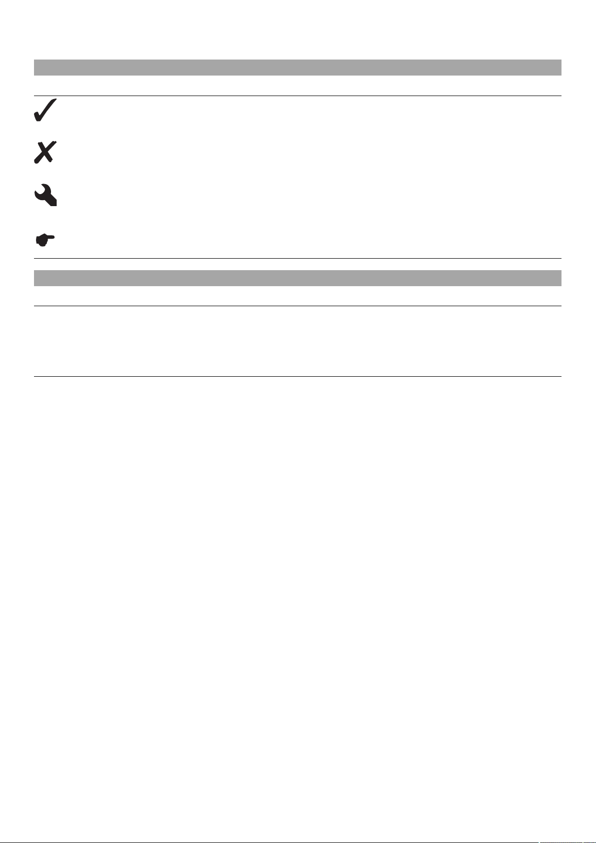
6.7 Light switch (FE EU, FE AUS)
The light switch 1 is fitted on the left side of the handlebar.
Possible states
Light off – Light switch is turned to the right. In this position, the light
is switched off.
Low beam on – Light switch is in the central position. In this position,
the low beam and tail light are switched on.
High beam on – Light switch is turned to the left. In this position, the
high beam and the tail light are switched on.
L00166-12
6.8 Light switch (FE 501 USA)
The light switch 1 is on the right of the speedometer.
Possible states
• Light off – Light switch is pressed in up to the stop. In this position, the light is
• Light on – Light switch is pulled out to the stop. In this position, the low beam
B01648-10
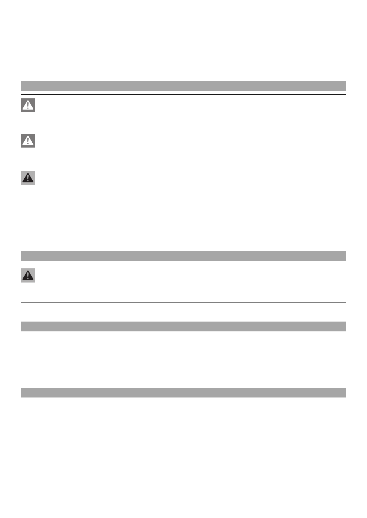
6.9 Turn signal switch (FE EU, FE AUS)
Turn signal switch 1 is fitted on the left side of the handlebar.
Possible states
L00171-10
switched off.
and tail light are switched on.
Turn signal light off – Turn signal switch is in the central position.
Turn signal light, left, on – Turn signal switch is turned to the left.
Turn signal light, right, on – Turn signal switch is turned to the right.
6.10 Emergency OFF switch (FE AUS)
101857-10
The emergency OFF switch 1 is fitted on the right side of the handlebar.
Possible states
Ignition off – the ignition circuit is open in this position, the engine
goes out if it was running, or does not start if it was off.
Ignition on – the ignition circuit is closed in this position and the
engine can be started.
6 CONTROLS 16
6.11 Electric starter button (FE EU, FE 501 USA)
The electric starter button 1 is fitted on the right side of the handlebar.
Possible states
• Electric starter button in basic position
• Electric starter button pressed – the electric starter is actuated in this position.
L00170-10
6.12 Electric starter button (FE AUS)
The electric starter button 1 is fitted on the right side of the handlebar.
Possible states
• Electric starter button in basic position
• Electric starter button pressed – the electric starter is actuated in this position.
101857-11
6.13 Overview of indicator lamps (FE EU, FE AUS)
Possible states
B01626-01
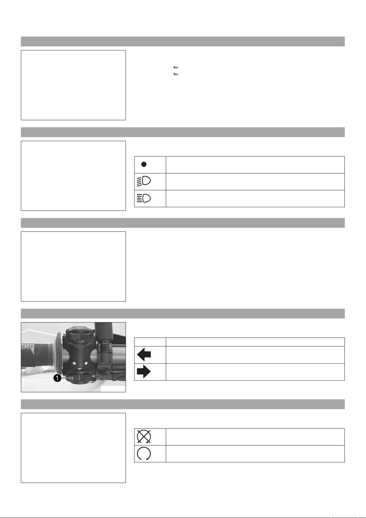
6.14 Overview of indicator lamps (FE 501 USA)
Possible states
High beam indicator light lights up blue – High beam is switched on.
FI warning lamp (MIL) lights up/flashes orange – The OBD has detected
an emission- or safety-critical fault.
The fuel level warning lamp lights up orange – The fuel level has
reached the reserve mark.
Turn signal indicator light flashes green – Turn signal is switched on.
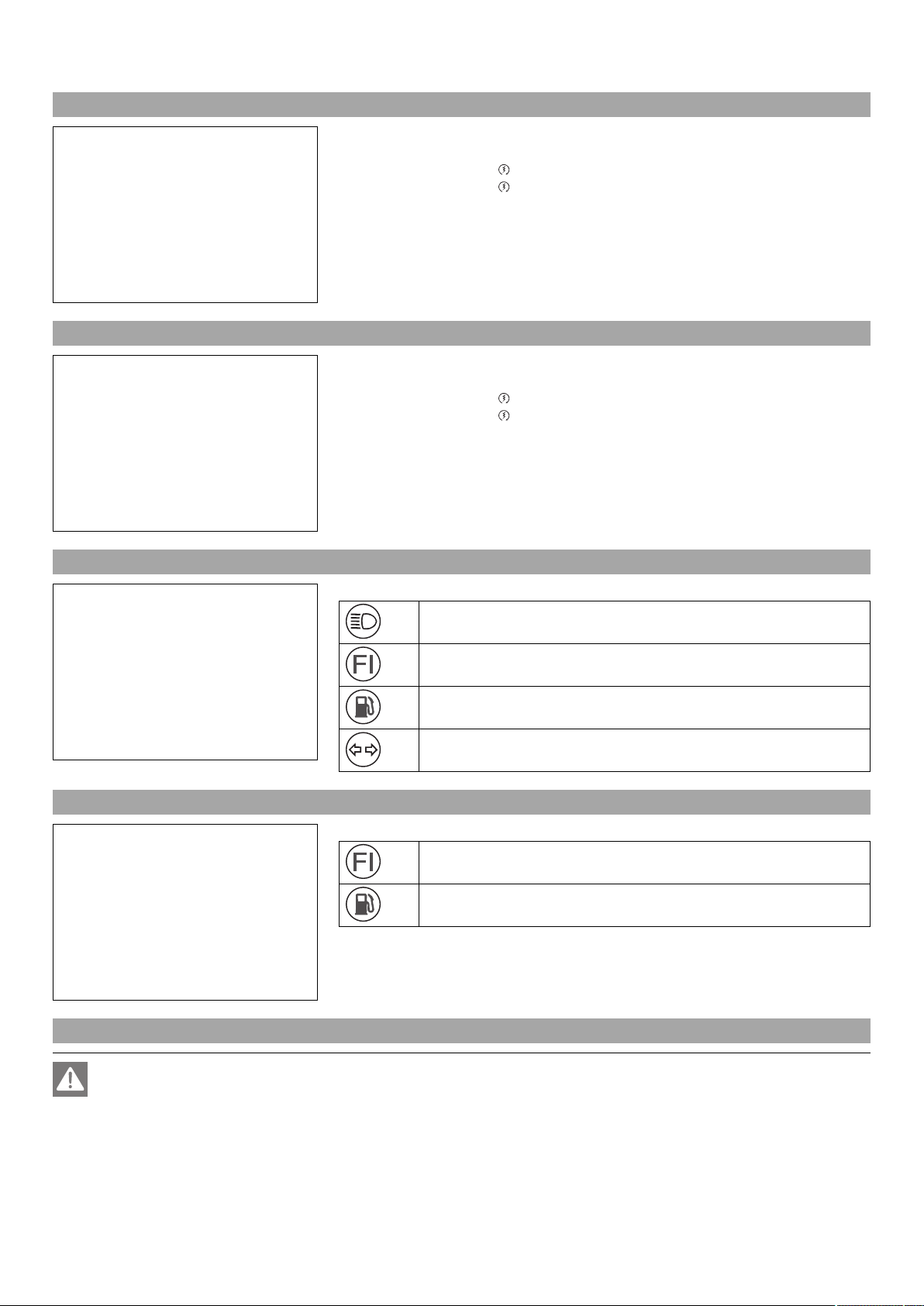
FI warning lamp (MIL) lights up/flashes orange – The OBD has detected
an emission- or safety-critical fault.
The fuel level warning lamp lights up orange – The fuel level has
reached the reserve mark.
B01648-01
6.15 Opening filler cap
Danger
Fire hazard Fuel is highly flammable.
– Never refuel the vehicle near open flames or burning cigarettes, and always switch off the engine first. Be careful that no
fuel is spilt, especially on hot vehicle components. Clean up spilt fuel immediately.
– The fuel in the fuel tank expands when warm and may emerge if overfilled. Follow the instructions on refueling.

6 CONTROLS 17
Warning
Danger of poisoning Fuel is poisonous and a health hazard.
– Fuel must not come into contact with the skin, eyes, or clothing. Do not breathe in the fuel vapors. If contact occurs with
the eyes, rinse with water immediately and contact a physician. Immediately clean contaminated areas on the skin with
soap and water. If fuel is swallowed, contact a physician immediately. Change clothing that is contaminated with fuel.
Store fuel properly in a suitable canister and keep away from children.
Warning
Environmental hazard Improper handling of fuel is a danger to the environment.
– Do not allow fuel to get into the ground water, the ground, or the sewage system.
– Press release button 1, turn filler cap counterclockwise and lift it upwards and
remove.
B01649-10
6.16 Closing filler cap
B01649-11
6.17 Idle speed adjusting screw
– Replace the filler cap and turn clockwise until the release button 1 locks in place.
Info
Route the fuel tank breather hose 2 without kinking.
The idle speed adjusting screw 1 is located on the throttle valve body at the top left.
The idle speed adjusting screw has two functions.
Turning it controls the idle speed.
Pulling it out all the way raises the idle speed during a cold start.
Possible states
• RPM increase activated – Idle speed adjusting screw is pulled out all the way.
• RPM increase deactivated – Idle speed adjusting screw is pushed in all the way.
B01253-10

6 CONTROLS 18
6.18 Shift lever
Shift lever 1 is mounted on the left side of the engine.
B01254-10
The gear positions can be seen in the photograph.
The neutral or idle position is between the first and second gears.
B01255-10
6.19 Foot brake lever
6.20 Side stand
Foot brake lever 1 is located in front of the right footrest.
The foot brake lever is used to activate the rear brake.
B01256-10
The side stand 1 is located on the left side of the vehicle.
L00187-10
The side stand is used for parking the motorcycle.
L00186-10
Info
When you are riding, the side stand 1 must be folded up and secured with rubber band 2.
6 CONTROLS 19
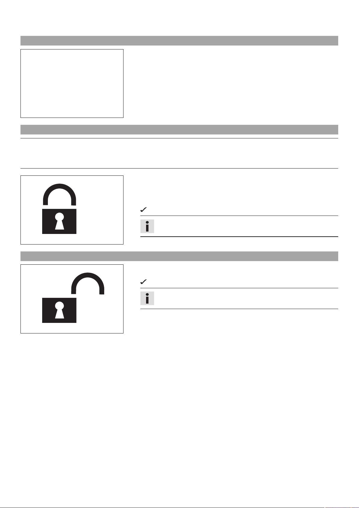
6.21 Steering lock (FE EU, FE AUS)
Steering lock 1 is fitted on the left side of the steering head.
The steering lock is used to lock the steering. Steering, and therefore riding, is no
longer possible.
L00188-10
6.22 Locking the steering (FE EU, FE AUS)
Note
Danger of damage The parked vehicle may roll away or fall over.
– Always place the vehicle on a firm and even surface.
– Park the vehicle.
– Turn the handlebar as far as possible to the right.
– Insert the key in the steering lock, turn it to the left, press it in and turn it to the
right. Remove the key.
Steering is no longer possible.
400732-01
6.23 Unlocking the steering (FE EU, FE AUS)
– Insert the key in the steering lock, turn it to the left, pull it out and turn it to the
right. Remove the key.
400731-01
Info
Never leave the key in the steering lock.
You can now steer the bike again.
Info
Never leave the key in the steering lock.
7 SPEEDOMETER 20
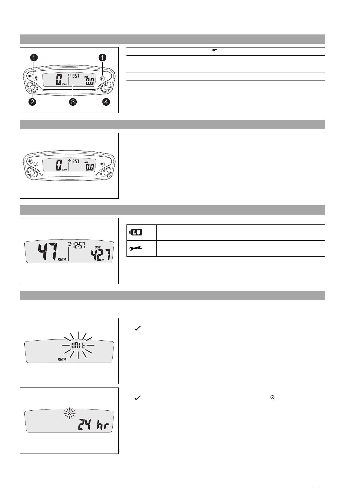
7.1 Overview
1 Overview of indicator lamps ( p. 16)
2 Left button
3 Display
4 Right button
401908-10
7.2 Activation
Activating the speedometer
The speedometer is activated when one of the buttons is pressed or an impulse comes
from the wheel speed sensor.
401908-01
7.3 Message on the speedometer
401901-01
7.4 Setting the speedometer
Possible states
Battery voltage of the speedometer – Battery voltage of the speedometer
is too low. Change the battery.
Service – A service is due. Contact an authorized HUSABERG workshop.
Condition
The motorcycle is stationary.
– Press both buttons for 3–5 seconds.
The Setup menu is displayed. The UNIT display flashes.
– Press one of the buttons to select UNIT for the speed in kilometers KM/H or miles
M/H.
401909-01
401911-01
– Wait for 5 seconds.
The speedometer changes to the next menu item. The symbol flashes.
– Press one of the buttons to select the 24h or 12h display of the clock.
7 SPEEDOMETER 21
– Wait for 5 seconds.
The speedometer changes to the next menu item. The symbol flashes.
Resetting the time
– Press the left button.
The value decreases.
Advancing the time
– Press the right button.
The value increases.
401912-01
– Wait for 5 seconds.
The speedometer changes to the next menu item. The symbol flashes.
– Set the service.
Guideline
One-time service after 1 h
Service every 15 h
Shortening the service interval
401913-01
– Press the left button.
The value decreases.
Extending the service interval
– Press the right button.
The value increases.
Switching off the service interval display
– Press and hold the left button.
off appears on the display.
401914-01
7.5 Setting kilometers or miles
Info
If you change the unit of measure, the ODO value is retained and converted accordingly.
Condition
The motorcycle is stationary.
– The Setup menu is displayed. The UNIT display flashes.
The Setup menu is displayed.
– Press one of the buttons to select UNIT for the speed in kilometers KM/H or miles
M/H.
401909-01
7 SPEEDOMETER 22
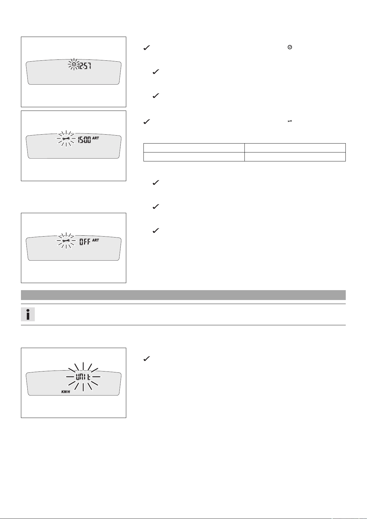
7.6 Setting the clock
Condition
The motorcycle is stationary.
– Press both buttons for 3–5 seconds.
The Setup menu is displayed. The UNIT display flashes.
– Wait for the menu of the clock to flash.
– Press one of the buttons to select the 24h or 12h display of the clock.
401911-01
– Wait for 5 seconds.
The speedometer changes to the next menu item. The symbol flashes.
Resetting the time
– Press the left button.
The value decreases.
Advancing the time
– Press the right button.
The value increases.
401912-01
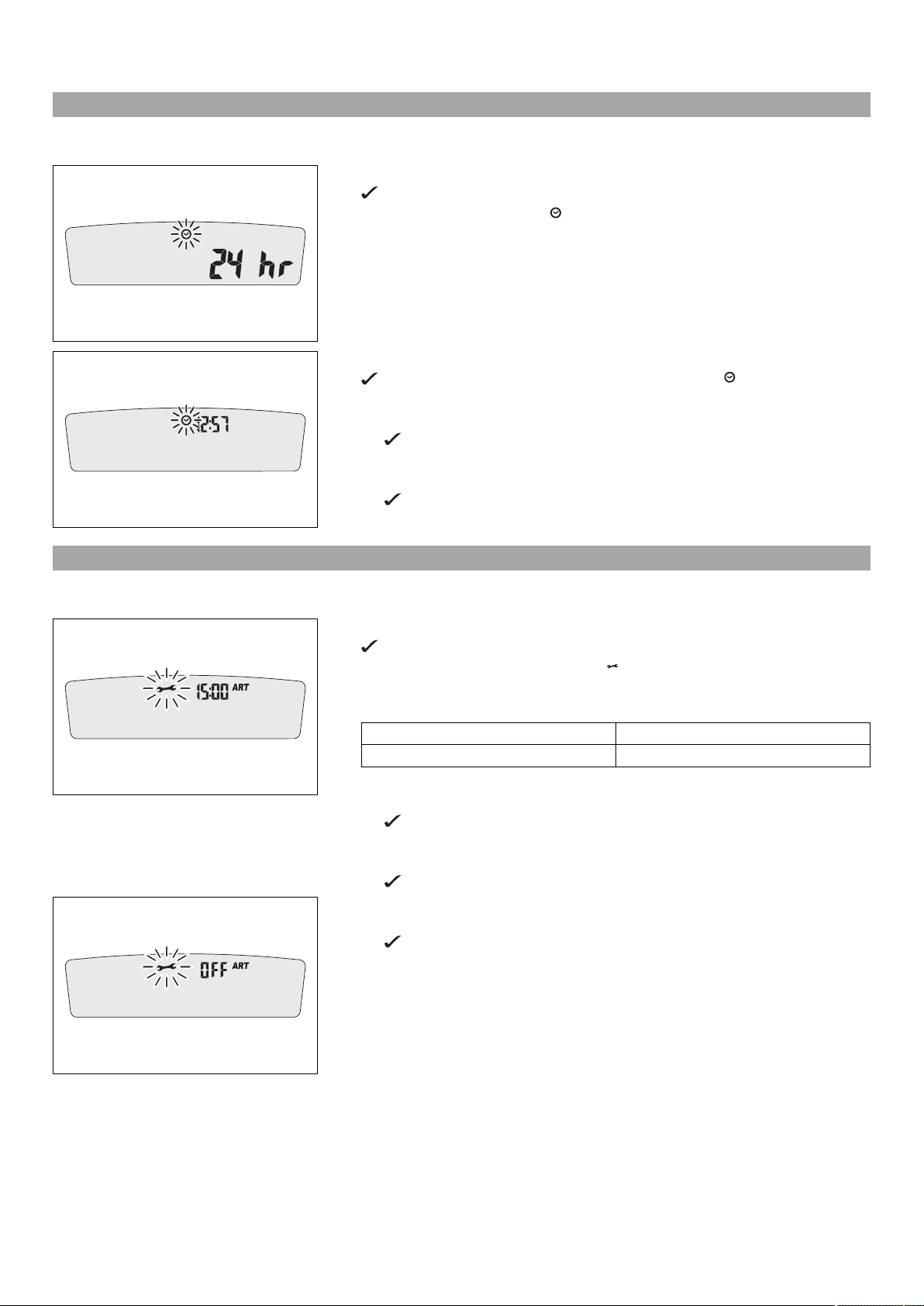
7.7 Setting the service display
401913-01
Condition
The motorcycle is stationary.
– Press both buttons for 3–5 seconds.
The Setup menu is displayed. The UNIT display flashes.
– Wait for the menu of the service display to flash.
– Set the service.
Guideline
One-time service after 1 h
Service every 15 h
Shortening the service interval
– Press the left button.
The value decreases.
Extending the service interval
– Press the right button.
The value increases.
Switching off the service interval display
– Press and hold the left button.
off appears on the display.
401914-01
7 SPEEDOMETER 23
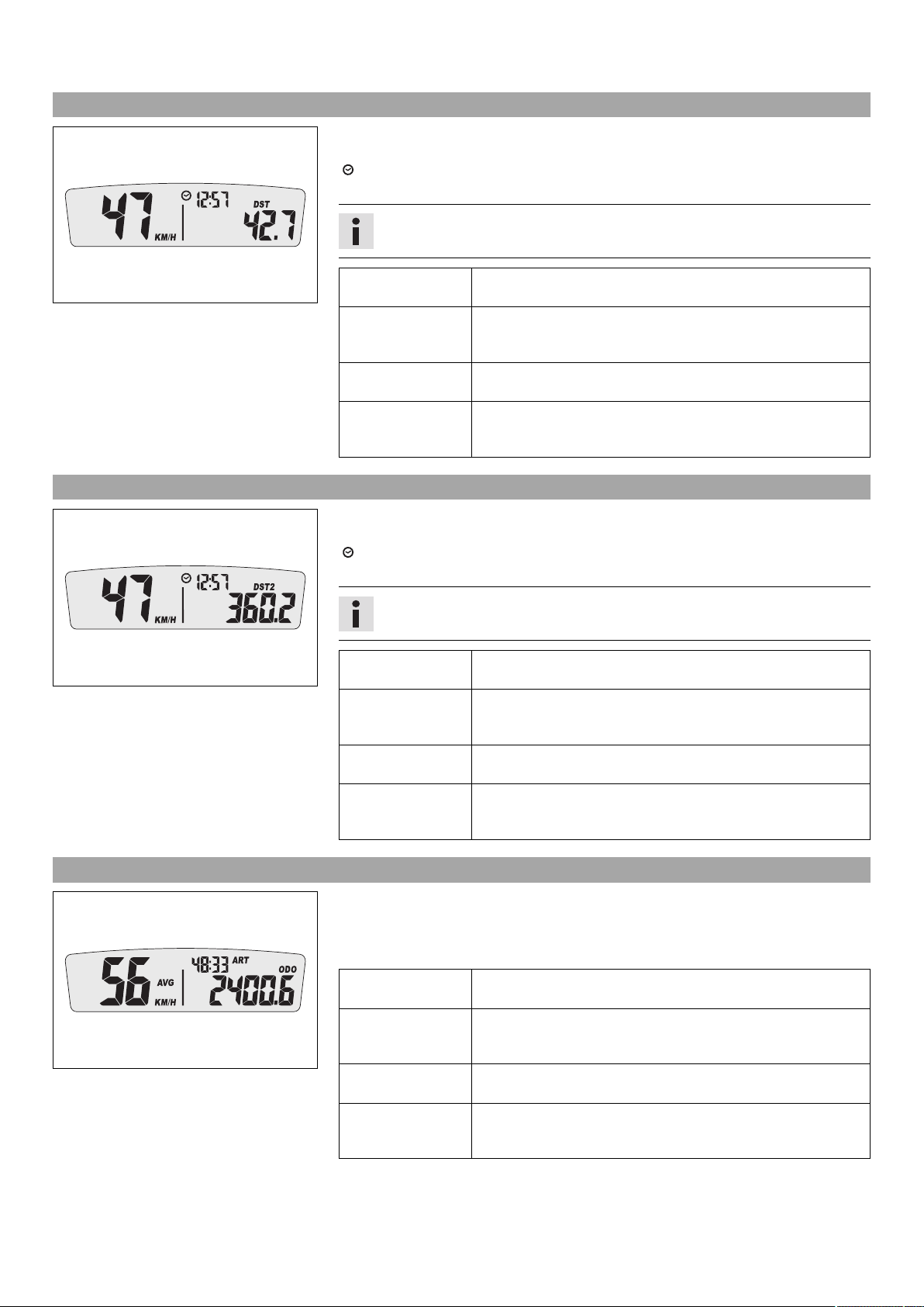
7.8 Speed, time, and DST distance 1
– Press one of the buttons until DST appears on the speedometer.
KM/H or M/H shows the speed.
shows the time.
DST shows the distance since the last reset, such as between two refueling stops.
Info
If the value of 39999.9 is exceeded, DST is automatically reset to 0.0.
Press the left but-
401901-01
ton briefly.
Press the left but-
ton for 3 – 5 seconds.
Press the right button briefly.
Press the right button for 3 – 5 seconds.
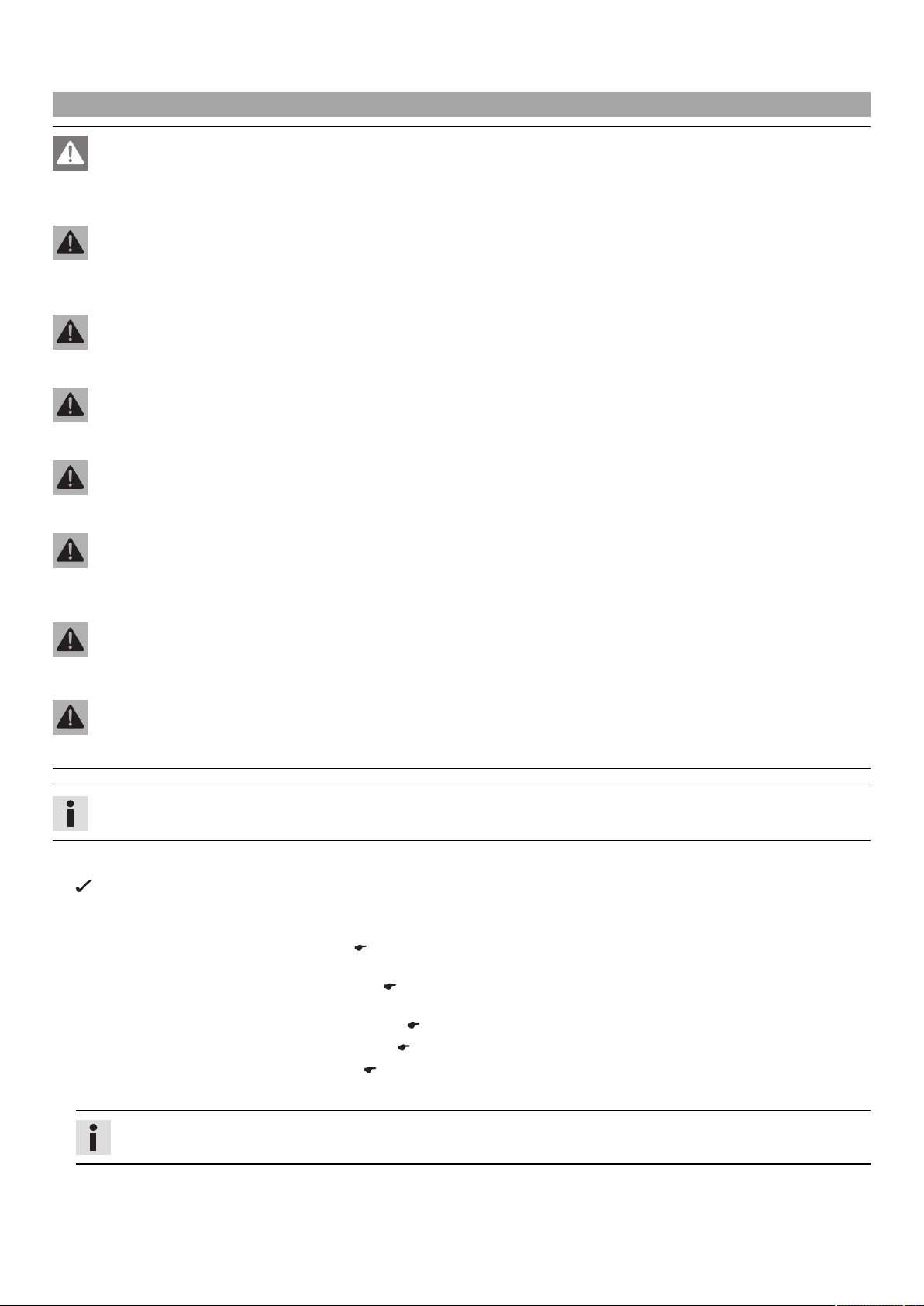
7.9 Speed, time, and DST2 distance 2
– Press one of the buttons until DST2 appears on the speedometer.
KM/H or M/H shows the speed.
DST2 shows the distance 2 since the last reset, such as between two refueling stops.
Press the left but-
401902-01
ton briefly.
Press the left but-
ton for 3 – 5 seconds.
Press the right button briefly.
Press the right button for 3 – 5 seconds.
Next display mode
DST can be preset to a value between 0.0 and 39999.9 by
pressing the buttons.
Next display mode
DST is reset to 0.0.
shows the time.
Info
If the value of 39999.9 is exceeded, DST2 is automatically reset to 0.0.
Next display mode
DST2 can be preset to a value between 0.0 and 39999.9 by
pressing the buttons.
Next display mode
DST2 is reset to 0.0.
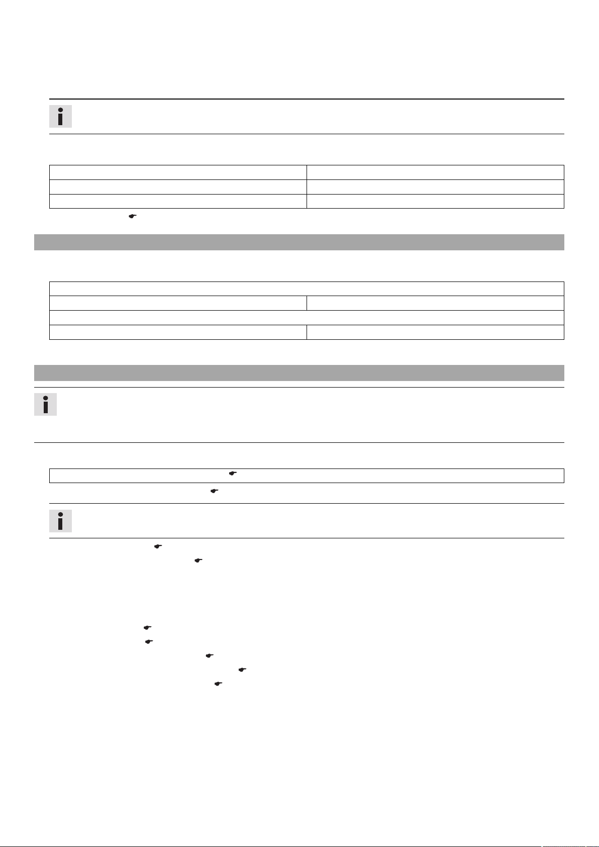
7.10 AVG average speed, ART operating hours, and ODO total distance covered
– Press one of the buttons until AVG, ART and ODO appear in the speedometer.
AVG shows the average speed since the last reset.
ART shows the operating hours.
ODO shows the total distance covered.
401903-01
Press the left button briefly.
Press the left button for 3 – 5 seconds.
Press the right button briefly.
Press the right button for 3 – 5 seconds.
Next display mode
The OPEN END WRENCH SYMBOL shows the remaining operating hours until the next service is due.
Next display mode
AVG is reset to 0.0.
8 PREPARING FOR USE 24
8.1 Advice on first use
Danger
Danger of accidents Danger arising from the rider's judgement being impaired.
– Do not operate the vehicle while under the influence of alcohol, drugs and certain medications or physically or mentally
impaired.
Warning
Risk of injury Missing or poor protective clothing presents an increased safety risk.
– Wear protective clothing (helmet, boots, gloves, pants and jacket with protectors) every time you ride the vehicle. Always
wear protective clothing that is in good condition and meets the legal requirements.
Warning
Danger of crashing Poor vehicle handling due to different tire tread patterns on front and rear wheels.
– The front and rear wheels must be fitted with tires with similar tread patterns to prevent loss of control over the vehicle.
Warning
Danger of accidents Critical riding behavior due to inappropriate riding.
– Adapt your riding speed to the road conditions and your riding ability.
Warning
Danger of accidents Accident risk caused by presence of a passenger.
– Your vehicle is not designed to carry passengers. Do not ride with a passenger.
Warning
Danger of accidents Failure of brake system.
– If the foot brake lever is not released, the brake linings drag continuously. The rear brake may fail due to overheating. Take
your foot off the foot brake lever when you are not braking.
Warning
Danger of accidents Unstable riding behavior.
– Do not exceed the maximum permissible weight and axle loads.
Warning
Risk of misappropriation Usage by unauthorized persons.
– Never leave the vehicle while the engine is running. Secure the vehicle against use by unauthorized persons.
Info
When using your motorcycle, remember that others may feel disturbed by excessive noise.
– Make sure that the pre-delivery inspection work has been carried out by an authorized HUSABERG workshop.
You receive a delivery certificate and the service record at vehicle handover.
– Before your first trip, read the entire operating instructions carefully.
– Get to know the controls.
– Adjust the basic position of the clutch lever. ( p. 61)
(FE EU, FE AUS)
– Adjust the free travel of the hand brake lever. ( p. 63)
(FE 501 USA)
– Adjust the basic position of the hand brake lever. ( p. 63)
–
Adjust the basic position of the foot brake lever. x ( p. 67)
–
Adjust the basic position of the shift lever. x ( p. 88)
– Get used to handling the motorcycle on a suitable piece of land before making a longer trip.
Info
Offroad, you should be accompanied by another person on another machine so that you can help each other.
– Try also to ride as slowly as possible and in a standing position to get a better feeling for the vehicle.
– Do not make any offroad trips that exceed your ability and experience.
8 PREPARING FOR USE 25
– Hold the handlebar firmly with both hands and keep your feet on the footrests when riding.
– If you carry any baggage, make sure it is fixed firmly as close as possible to the center of the vehicle and ensure even weight dis-
tribution between the front and rear wheels.
Info
Motorcycles react sensitively to any changes in weight distribution.
– Do not exceed the overall maximum permitted weight and the axle loads.
Guideline
Maximum permissible overall weight 335 kg (739 lb.)
Maximum permissible front axle load 145 kg (320 lb.)
Maximum permissible rear axle load 190 kg (419 lb.)
– Run in the engine. ( p. 25)
8.2 Running-in the engine
– During the running-in phase, do not exceed the specified engine speed and engine performance.
Guideline
Maximum engine speed
During the first operating hour 7,000 rpm
Maximum engine performance
During the first 3 operating hours ≤ 75 %
– Avoid fully opening the throttle!
8.3 Preparing the vehicle for difficult riding conditions
Info
Use of the vehicle under difficult conditions, such as on sand or on wet and muddy surfaces, can lead to considerably more
rapid wear of components such as the drive train, brake system, or suspension components. For this reason, it may be necessary to inspect or replace parts before the next scheduled service.
– HUSABERG recommends that you use the specified engine oil for difficult riding conditions and to increase performance.
Engine oil (SAE 10W/60) (00062010035) ( p. 106)
–
Clean the air filter and air filter box. x ( p. 51)
Info
Check the air filter approx. every 30 minutes.
–
Seal the air filter box. x ( p. 51)
– Additionally secure the rubber grip. ( p. 61)
– Check the electrical connector for humidity and corrosion and to ensure it is firmly seated.
» If humidity, corrosion or damage is found:
– Clean and dry the connector, or change it if necessary.
Difficult riding conditions are:
– Rides on dry sand. ( p. 26)
– Rides on wet sand. ( p. 26)
– Rides on wet and muddy surfaces. ( p. 27)
– Rides at high temperature and slow speed. ( p. 27)
– Rides at low temperature or in snow. ( p. 27)
8 PREPARING FOR USE 26
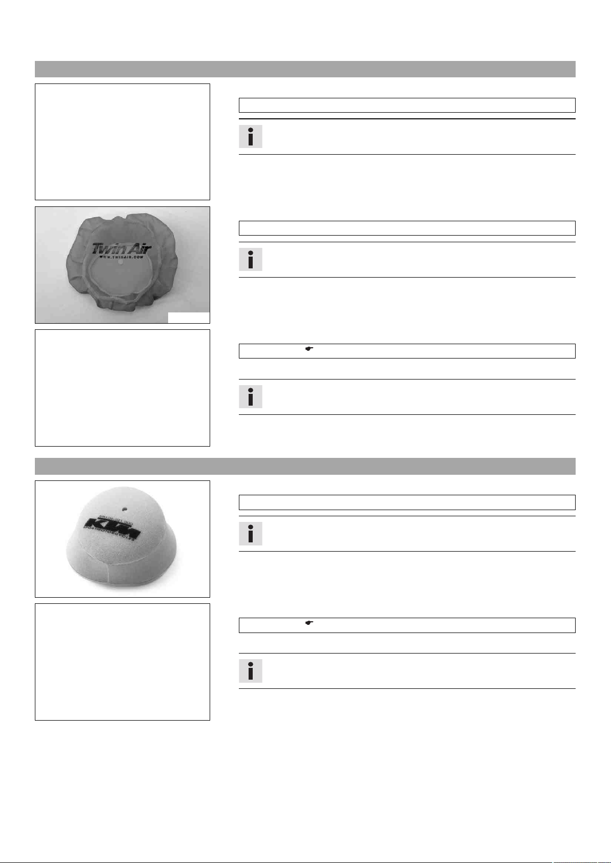
8.4 Preparing for rides on dry sand
– Fit a dust cover on the air filter.
Dust protection device for air filter (77206920000)
Info
See the HUSABERG Pure Tech fitting instructions.
600869-01
– Fit a sand cover on the air filter.
Sand protection device for air filter (59006022000)
Info
See the HUSABERG Pure Tech fitting instructions.
600871-01
– Clean the chain.
600868-01
8.5 Preparing for rides on wet sand
600870-01
Chain cleaner ( p. 108)
– Fit the steel sprocket.
Tip
Do not grease the chain.
– Clean the radiator fins.
– Straighten bent radiator fins carefully.
– Fit a rain cover on the air filter.
Waterproofing device for air filter (77206921000)
Info
See the HUSABERG Pure Tech fitting instructions.
– Clean the chain.
Chain cleaner ( p. 108)
– Fit the steel sprocket.
600868-01
Tip
Do not grease the chain.
– Clean the radiator fins.
– Straighten bent radiator fins carefully.
8 PREPARING FOR USE 27
8.6 Preparing for rides on wet and muddy surfaces
– Fit a rain cover on the air filter.
Waterproofing device for air filter (77206921000)
Info
See the HUSABERG Pure Tech fitting instructions.
600870-01
– Fit the steel sprocket.
– Clean the motorcycle. ( p. 93)
– Straighten bent radiator fins carefully.
600868-01
8.7 Preparing for rides at high temperature and slow speed
– Adjust the secondary drive to the road conditions.
Info
The engine oil heats up quickly when the clutch is operated frequently due
to an excessively high secondary drive.
– Clean the chain.
Chain cleaner ( p. 108)
600868-01
– Clean the radiator fins.
– Straighten bent radiator fins carefully.
– Check the coolant level. ( p. 85)
8.8 Preparing for rides at low temperature or in snow
– Fit a rain cover on the air filter.
Waterproofing device for air filter (77206921000)
Info
See the HUSABERG Pure Tech fitting instructions.
600870-01
9 RIDING INSTRUCTIONS 28
9.1 Checks and maintenance work when preparing for use
Info
Before riding the vehicle, always check its condition and operating safety.
The vehicle must be in perfect technical condition when used.
– Check the engine oil level. ( p. 89)
– Check the electrical system.
– Check the front brake fluid level. ( p. 64)
– Check the rear brake fluid level. ( p. 68)
– Check the front brake linings. ( p. 65)
– Check the rear brake linings. ( p. 69)
– Check that the brake system is functioning properly.
– Check the coolant level. ( p. 85)
– Check for chain dirt accumulation. ( p. 56)
– Check the chain, rear sprocket, engine sprocket and chain guide. ( p. 58)
– Check the chain tension. ( p. 57)
– Check the tire condition. ( p. 74)
– Check the tire air pressure. ( p. 75)
– Check the spoke tension. ( p. 75)
– Clean the dust boots of the fork legs. ( p. 41)
– Bleed fork legs. ( p. 41)
– Check the air filter.
– Check the settings of all controls and ensure that they can be operated smoothly.
– Check all screws, nuts, and hose clamps regularly for tightness.
– Check the fuel supply.
9.2 Starting
Danger
Danger of poisoning Exhaust gases are toxic and inhaling them may result in unconsciousness and/or death.
– When running the engine, always make sure there is sufficient ventilation, and do not start or run the engine in an enclosed
space without an effective exhaust extraction system.
Note
Engine failure High engine speeds in cold engines have a negative effect on the service life of the engine.
– Always warm up the engine at low engine speeds.
– Raise the motorcycle off of the stand and secure the stand with the rubber band 1.
– Shift transmission to neutral.
(FE AUS)
– Turn the emergency OFF switch to the position .
Condition
Ambient temperature: < 20 °C (< 68 °F)
– Pull the idle speed adjusting screw all the way out.
L00186-11
– Press the electric starter button.
Info
Press the electric starter button for at most 5 seconds. Wait for a least 5
seconds before trying again.
Warning lamp FI lights up briefly as a functional control when starting.
400733-01
 Loading...