


Husaberg fe 450 2009, fe 570 2009 Owners manual
OWNER'S MANUAL
FE 450 EU
FE 450 AUS
FE 450 USA
FE 570 EU
FE 570 AUS
FE 570 USA
2009
ART. NO. 3802014en

DEAR HUSABERG CUSTOMER 1
DEARHUSABERG CUSTOMER
Congratulations on your decision to purchase a HUSABERG motorcycle. You are now the owner of a state-of-the-art sports motorcycle
that will give you enormous pleasure if you service and maintain it accordingly.
We wish you great pleasure riding the vehicle!
Enter the serial numbers of your vehicle below.
Chassis number ( p. 9) Dealer's stamp
Engine number ( p. 9)
Key number (FE EU, FE AUS) ( p. 9)
The owner's manual corresponded to the latest state of this series at the time of printing. Slight deviations resulting from continuing
development and design of our motorcycles can however not be completely excluded.
All specifications are non-binding. HUSABERG, a division of KTM SMC AG (referred to herein as HUSABERG), specifically reserves
the right to modify or delete technical specifications, prices, colors, forms, materials, services, designs, equipment, etc., without prior
notice and without specifying reasons, to adapt these to local conditions, as well as to stop production of a particular model without
prior notice. HUSABERG accepts no liability for delivery options, deviations from illustrations and descriptions, as well as printing and
other errors. The models portrayed partly contain special equipment that does not belong to the regular scope of delivery.
© 2008 by HUSABERG eine Division der KTM SMC AG, Mattighofen Austria
All rights reserved
Reproduction, even in part, is permitted only with the express written permission of the copyright owner.
ISO 9001(12 100 6061)
Within the meaning of the international quality management standard ISO 9001, HUSABERG uses quality assurance
processes that lead to the maximum possible quality of the products.
Issued by: TÜV Management Service
HUSABERG eine Division der KTM SMC AG
5230 Mattighofen, Austria

CONTENTS 2
CONTENTS
MEANS OF REPRESENTATION ............................................ 4
IMPORTANT NOTES............................................................ 5
VIEW OF VEHICLE............................................................... 7
View of the vehicle from the left front (example) ................. 7
View of the vehicle from the right rear (example) ................ 8
LOCATION OF SERIAL NUMBERS ........................................ 9
Chassis number............................................................... 9
Type label (FE EU, FE AUS) ............................................. 9
Type label (FE USA) ........................................................ 9
Key number (FE EU, FE AUS)........................................... 9
Engine number................................................................ 9
Fork part number........................................................... 10
Shock absorber part number ........................................... 10
CONTROLS....................................................................... 11
Clutch lever .................................................................. 11
Hand brake lever ........................................................... 11
Short circuit button (FE EU, FE AUS).............................. 11
Short circuit button (FE USA) ......................................... 11
Emergency OFF switch (FE AUS) .................................... 11
Electric starter button (FE EU, FE USA) .......................... 12
Electric starter button (FE AUS)...................................... 12
Light switch (FE EU, FE AUS) ........................................ 12
Horn button (FE EU, FE AUS)......................................... 12
Flasher switch (FE EU, FE AUS) ..................................... 12
Overview of indicator lamps (FE EU, FE AUS) .................. 13
Overview of indicator lamps (FE USA).............................. 13
Speedometer................................................................. 13
Speedometer activation and test ..................................... 13
Tripmaster switch .......................................................... 14
Setting kilometers or miles ............................................. 14
Setting the clock ........................................................... 14
Adjusting the speedometer functions............................... 15
Querying the lap time .................................................... 15
SPEED display mode (speed).......................................... 16
SPEED/H display mode (service hours) ............................ 16
SPEED/CLK display mode (time)..................................... 16
SPEED/LAP display mode (lap time)................................ 16
SPEED/ODO display mode (odometer) ............................. 17
SPEED/TR1 display mode (trip master 1)......................... 17
SPEED/TR2 display mode (trip master 2)......................... 17
SPEED/A1 display mode (average speed 1) ...................... 18
SPEED/A2 display mode (average speed 2) ...................... 18
SPEED/S1 display mode (stop watch 1) ........................... 18
SPEED/S2 display mode (stop watch 2) ........................... 18
Opening the filler cap .................................................... 19
Closing the filler cap...................................................... 20
Idle speed adjusting screw ............................................. 20
Seat release .................................................................. 20
Shift lever..................................................................... 20
Foot brake pedal ........................................................... 21
Side stand .................................................................... 21
Steering lock (FE EU, FE AUS) ....................................... 21
Locking the steering (FE EU, FE AUS) ............................. 21
Unlocking the steering (FE EU, FE AUS).......................... 22
GENERAL TIPS AND HINTS ON PUTTING INTO
OPERATION...................................................................... 23
Advice on first use ......................................................... 23
Running in the engine.................................................... 24
RIDING INSTRUCTIONS .................................................... 25
Checks before putting into operation ............................... 25
Starting ........................................................................ 25
Starting up ................................................................... 26
Shifting, riding.............................................................. 26
Stopping, parking .......................................................... 27
Refueling...................................................................... 27
SERVICE SCHEDULE......................................................... 29
Important maintenance work to be carried out by an
authorized HUSABERG workshop.................................... 29
Important maintenance work to be carried out by an
authorized HUSABERG workshop. (as additional order) ..... 30
Important checks and maintenance work to be carried
out by the rider ............................................................. 31
MAINTENANCE WORK ON CHASSIS AND ENGINE .............. 32
Jacking up the motorcycle .............................................. 32
Removing the motorcycle from the work stand.................. 32
Checking the basic chassis setting with the rider's
weight .......................................................................... 32
Compression damping of shock absorber.......................... 32
Adjusting the high-speed compression damping of the
shock absorber .............................................................. 32
Adjusting the low-speed compression damping of the
shock absorber .............................................................. 33
Adjusting the rebound damping of the shock absorber....... 33
Measuring rear wheel sag unloaded ................................. 34
Checking the static sag of the shock absorber .................. 34
Checking the riding sag of the shock absorber .................. 35
Adjusting the spring preload of the shock absorber x ...... 35
Adjusting the riding sag x............................................. 36
Removing the shock absorber x..................................... 36
Installing the shock absorber x ..................................... 36
Checking the basic setting of the fork .............................. 37
Adjusting the compression damping of the fork ................ 37
Adjusting the rebound damping of the fork....................... 37
Adjusting the spring preload of the fork ........................... 38
Bleeding the fork legs .................................................... 38
Cleaning the dust boots of the fork legs ........................... 38
Loosening the fork protection.......................................... 39
Positioning the fork protection ........................................ 39
Checking the play of the steering head bearing................. 39
Adjusting the play of the steering head bearing x............ 40
Handlebar position ........................................................ 40
Adjusting the handlebar position x................................ 40
Checking the gas Bowden cable route.............................. 41
Checking the play in the gas Bowden cable...................... 41
Adjusting the play in the gas Bowden cable x................. 41
Checking for chain dirt accumulation .............................. 42
Cleaning the chain......................................................... 42
Checking the chain tension ............................................ 42
Adjusting the chain tension ............................................ 43
Checking the rear sprocket/engine sprocket for wear ......... 43
Checking the chain wear ................................................ 44
Adjusting the chain guide x.......................................... 44
Checking the brake discs................................................ 44
Checking the free travel of the hand brake lever ............... 45
Adjusting the basic position of the handbrake lever
(FE USA) ...................................................................... 45
Adjusting the free travel of the handbrake lever (FE EU,
FE AUS) ....................................................................... 46
Checking the front brake fluid level................................. 46
Adding front brake fluid x ............................................ 46
Checking the front brake linings...................................... 47
Changing the front brake linings x................................. 47
Checking the free travel of the foot brake lever ................. 49

CONTENTS 3
Adjusting the basic position of the footbrake lever x ....... 49
Checking the rear brake fluid level .................................. 50
Adding rear brake fluid x.............................................. 50
Checking the rear brake linings ....................................... 51
Changing the rear brake linings x.................................. 51
Removing the front wheel x .......................................... 52
Installing the front wheel x........................................... 53
Removing the rear wheel x ........................................... 54
Installing the rear wheel x ............................................ 54
Checking the tire condition............................................. 55
Checking the tire air pressure ......................................... 55
Checking the spoke tension ............................................ 56
Removing the seat ......................................................... 56
Mounting the seat ......................................................... 56
Removing the battery x ................................................ 56
Installing the battery x................................................. 57
Recharging the battery x .............................................. 58
Changing the main fuse ................................................. 59
Changing the fuses of individual power consumers............ 59
Checking the headlight adjustment ................................. 60
Adjusting the beam width of the headlight ....................... 61
Removing the headlight mask with the headlight .............. 61
Installing the headlight mask with the headlight ............... 61
Changing the headlight bulb........................................... 61
Removing the spoiler ..................................................... 62
Installing the spoiler ...................................................... 62
Removing the air filter x............................................... 62
Installing the air filter x ............................................... 63
Cleaning air filter x...................................................... 63
Removing the fuel tank x ............................................. 63
Installing the fuel tank x .............................................. 65
Cooling system .............................................................. 66
Checking the antifreeze and coolant level ........................ 66
Checking the coolant level.............................................. 67
Draining the coolant x.................................................. 67
Refilling coolant x ....................................................... 68
Removing the main silencer............................................ 68
Installing the main silencer ............................................ 68
Changing the glass fiber yarn filling of the main
silencer x ................................................................... 69
Adjusting the basic position of the clutch lever................. 69
Checking the fluid level of the hydraulic clutch ................ 69
Changing the hydraulic clutch fluid x ............................ 70
Adjusting the idle speed x............................................ 71
Removing the engine guard ............................................ 71
Installing the engine guard ............................................. 71
Checking the engine oil level .......................................... 71
Adding engine oil .......................................................... 72
Changing the engine oil and oil filter, cleaning the
engine oil screen x ...................................................... 72
Draining engine oil, cleaning engine oil screen x ............ 72
Removing the oil filter x............................................... 73
Installing the oil filter x ............................................... 73
Filling up with engine oil x........................................... 74
TROUBLESHOOTING......................................................... 75
FLASH CODE .................................................................... 77
CLEANING........................................................................ 79
Cleaning the motorcycle ................................................. 79
PROTECTION FOR WINTER OPERATION............................. 81
Protection for winter operation ........................................ 81
STORAGE ......................................................................... 82
Storage......................................................................... 82
Putting into operation after storage ................................. 82
TECHNICAL DATA - ENGINE .............................................. 83
Capacity - engine oil ...................................................... 83
Capacity - coolant.......................................................... 83
TECHNICAL DATA - ENGINE TIGHTENING TORQUES .......... 84
TECHNICAL DATA - CHASSIS ............................................ 86
Lighting equipment ....................................................... 86
Tires ............................................................................ 87
Capacity - fuel............................................................... 87
TECHNICAL DATA - FORK.................................................. 88
TECHNICAL DATA - SHOCK ABSORBER ............................. 89
TECHNICAL DATA - CHASSIS TIGHTENING TORQUES ........ 90
SUBSTANCES................................................................... 91
AUXILIARY SUBSTANCES.................................................. 93
STANDARDS..................................................................... 95
INDEX .............................................................................. 96

MEANS OF REPRESENTATION 4
Symbols used
The symbols used are explained in the following.
Indicates an expected reaction (e.g. of a work step or a function).
Indicates an unexpected reaction (e.g. of a work step or a function).
All work marked with this symbol requires specialist knowledge and technical understanding. In the interest of
your own safety, have these jobs done in an authorized HUSABERG workshop! There, your motorcycle will be serviced optimally by specially trained experts using the specialist tools required.
Identifies a page reference (more information is provided on the specified page).
Formats used
The typographical and other formats used are explained in the following.
Name Identifies a proprietary name.
®
Name
Brand™ Identifies a trademark.
Identifies a protected name.
IMPORTANT NOTES 5
Use definition (FE EU, FE AUS)
HUSABERG sport motorcycles are designed and built to withstand the normal stresses and strains of competitive use. The motorcycles
comply with currently valid regulations and categories of the top international motorsport organizations.
Info
The motorcycle is authorized for public road traffic in the homologous (reduced) version only.
In the derestricted version, the motorcycle may only be used in closed off areas remote from public road traffic.
The motorcycle is designed for off-road sport endurance competition (Enduro) and not for the predominant motocross use.
Use definition (FE USA)
HUSABERG sport motorcycles are designed and built to withstand the normal stresses and strains of competitive use. The motorcycles
comply with currently valid regulations and categories of the top international motorsport organizations.
Info
The motorcycle may only be used in closed off areas remote from public road traffic.
The motorcycle is designed for off-road sport endurance competition (Enduro) and not for predominant motocross use.
Maintenance
A prerequisite for perfect operation and prevention of wear is that the engine and chassis maintenance and adjustment work described
in the owner's manual are properly carried out. Poor adjustment and tuning of the engine and chassis can lead to damage and breakage of components.
Using the motorcycle in extreme conditions such as very muddy or wet terrain can lead to above-average wear of components such as
the transmission train or the brakes. For this reason, it may be necessary to service or replace worn parts before the limit specified in
the service schedule is reached.
Pay careful attention to the prescribed running-in period, inspection and maintenance intervals. If you observe these exactly, you will
ensure a much longer service life for your motorcycle.
Warranty
The work prescribed in the service schedule must be carried out in an authorized HUSABERG workshop and confirmed in the
customer's service record, since otherwise no warranty claims will be recognized. No warranty claims can be considered for damage
resulting from manipulations and/or alterations to the vehicle.
Fuel, oils, etc.
You should use the fuels, oils and greases according to specifications as listed in the owner's manual.
Spare parts, accessories
For your own safety, only use spare parts and accessory products that are approved and/or recommended by HUSABERG and have
them installed by an authorized HUSABERG workshop. HUSABERG accepts no liability for other products and any resulting damage
or loss.
The current HUSABERG Parts for your vehicle can be found on the HUSABERG website.
International HUSABERG website: www.husaberg.com
Work rules
When the vehicle is assembled, non-reusable parts (e.g., self-locking screws and nuts, gaskets, seal rings, O-rings, splints, lock washers) must be replaced with new parts.
Where thread lockers are used on screw connections (e.g., Loctite®), follow the instructions for use from the manufacturer.
After disassembly, clean the parts that are to be reused and check them for damage and wear. Replace damaged or worn parts.
After you complete the repair or maintenance work, check the roadworthiness of the vehicle.
Transport
Note
Danger of damage The parked vehicle can roll away or fall over.
– Always place the vehicle on a firm and even surface.
Note
Fire hazard Some vehicle components get very hot when the machine is driven.
– Do not place the vehicle where there are flammable or explosive substances. Do not place objects over the vehicle while it is still
warm from being run. Always let the vehicle cool first.
IMPORTANT NOTES 6
– Switch off the engine.
– Use straps or other suitable devices to secure the motorcycle against accidents or falling over.
Environment
Motorcycling is a wonderful sport and we naturally hope that you can enjoy it to the full. However, it is a potential problem for the
environment and can lead to conflicts with other persons. But if you use your motorcycle responsibly, you can ensure that such problems and conflicts do not have to occur. To protect the future of motorcycle sport, make sure that you use your motorcycle legally, display environmental consciousness, and respect the rights of others.
Notes/warnings
Pay close attention to the notes/warning.
Info
Various information and warning labels are affixed to the vehicle. Do not remove information/warning labels. If they are missing, you or others may not recognize dangers and may therefore be injured.
Grades of risks
Danger
Identifies a danger that will immediately and invariably lead to fatal or serious permanent injury if the appropriate measures
are not taken.
Warning
Identifies a danger that is likely to lead to fatal or serious injury if the appropriate measures are not taken.
Note
Identifies a danger that will lead to considerable machine and material damage if the appropriate measures are not taken.
Warning
Identifies a danger that will lead to environmental damage if the appropriate measures are not taken.
Owner's manual
– It is important that you read this owner's manual carefully and completely before making your first trip. It contains useful infor-
mation and many tips on how to operate and handle your motorcycle. Only then will you find out how to best customize the motorcycle for your own use and how you can protect yourself from injury. The owner's manual also contains important information on
servicing the motorcycle.
– The owner's manual is an important component of the motorcycle and should be handed over to the new owner if the vehicle is
sold.
Tampering warning
The exhaust system on this vehicle has no owner serviceable parts. Should there be an increase in noise or damage to any component
relating to the noise reduction system, replacement parts should be fitted by an authorized dealer.
Tampering with the noise control system is prohibited. Owners are warned that the law may prohibit:
1 The removal or rendering inoperative by any person other than for purposes of maintenance, repair or replacement, of any device
or element of design incorporated into any new vehicle for the purpose of noise control prior to its sale or delivery to the ultimate
purchaser or while it is in use;
2 The use of the vehicle after such device or element of design has been removed or rendered inoperative by any person.
VIEW OF VEHICLE 7
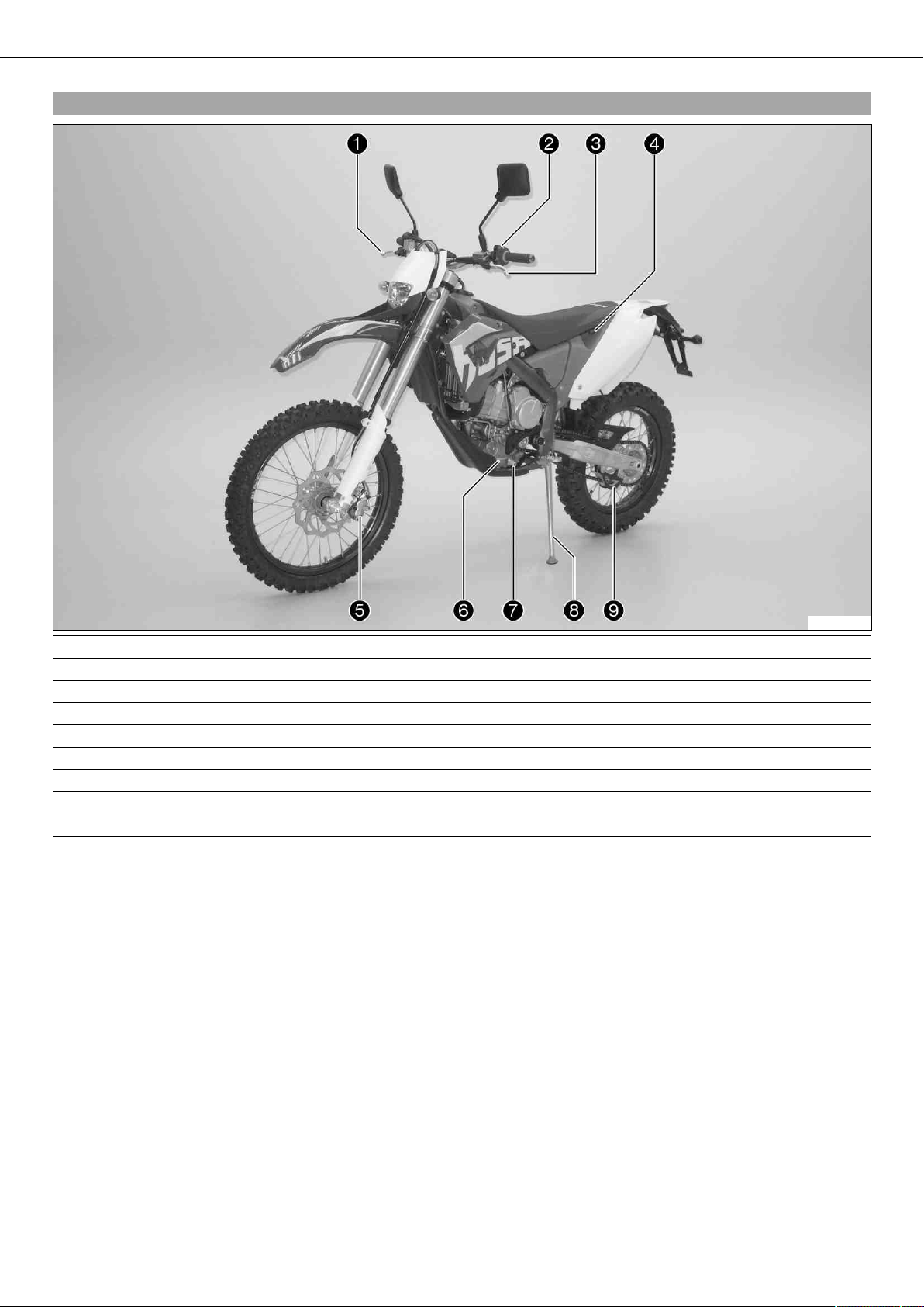
3.1View of the vehicle from the left front (example)
1 Hand brake lever
2 Light switch, short circuit button, horn button
3 Clutch lever
4 Seat release
5 Front brake caliper
6 Engine number
7 Shift lever
8 Side stand
9 Chain guide
100364-10
VIEW OF VEHICLE 8
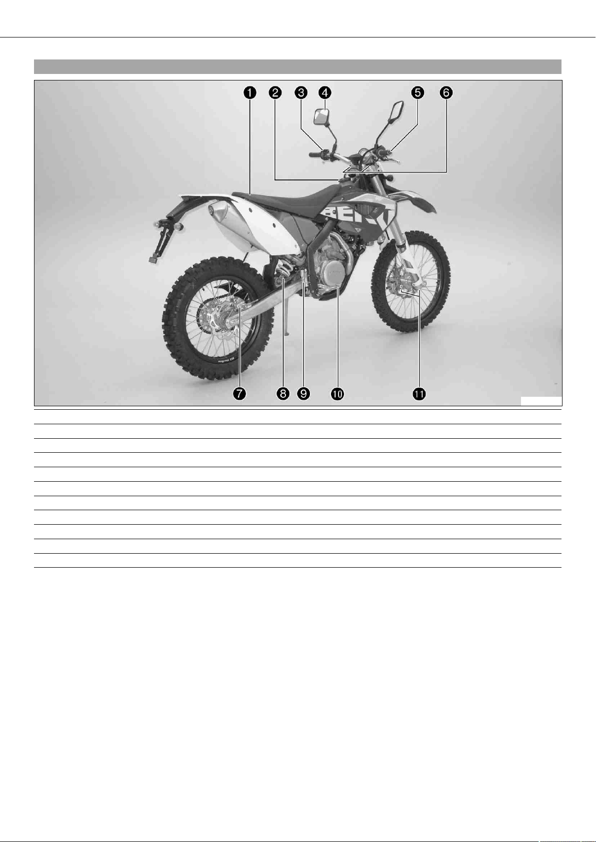
3.2View of the vehicle from the right rear (example)
1 Seat
2 Filler cap
3 Light switch
4 Rear mirror
5 Throttle grip
6 Fork rebound adjustment
7 Rear brake caliper
8 Shock absorber, rebound damping
9 Foot brake cylinder
10 Foot brake pedal
11 Fork compression adjustment
100365-10
LOCATION OF SERIAL NUMBERS 9
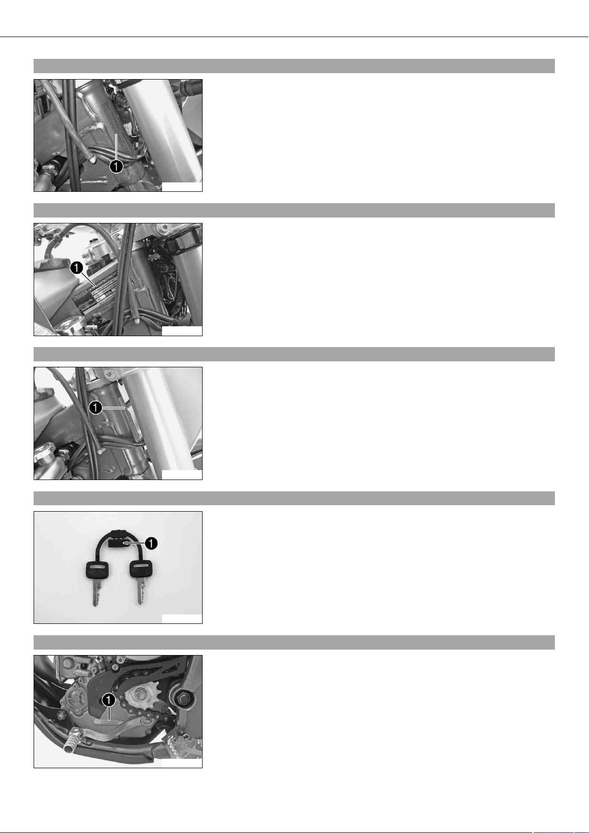
4.1Chassis number
The chassis number is stamped on the right side of the steering head.
100345-10
4.2Type label (FE EU, FE AUS)
The type label is fixed to the frame at the front right.
4.3Type label (FE USA)
4.4Key number (FE EU, FE AUS)
100458-10
The type label is fixed to the front of the steering head.
100464-10
The key number is stamped on the key strap.
4.5Engine number
500125-10
The engine number is stamped on the left side of the engine under the engine
sprocket.
100347-10
LOCATION OF SERIAL NUMBERS 10
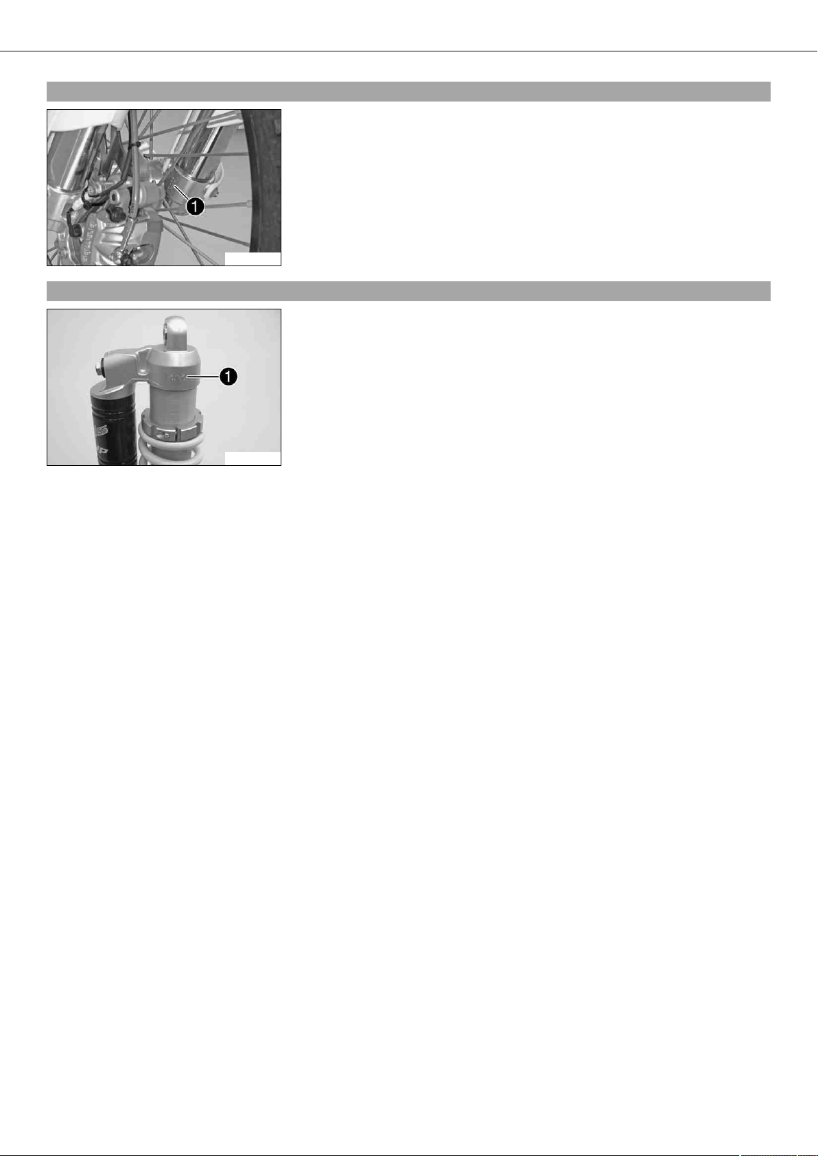
4.6Fork part number
The fork part number is stamped on the inner side of the fork stub.
100348-10
4.7Shock absorber part number
The shock absorber part number is stamped on the upper part of the shock absorber
above the adjusting ring. The shock absorber part number is not visible when the shock
absorber is installed.
100419-10
CONTROLS 11
5.1Clutch lever
The clutch lever is fitted on the left side of the handlebar.
The clutch is hydraulically operated and self-adjusting.
100349-10
5.2Hand brake lever
Hand brake lever is located on the right side of the handlebar.
The hand brake lever is used to activate the front brake.
100350-10
5.3Short circuit button (FE EU, FE AUS)
100353-10
5.4Short circuit button (FE USA)
Short circuit button is fitted on the left side of the handlebar.
Possible states
• Short circuit button in basic position – In this position, the ignition circuit is
closed, and the engine can be started.
• Short circuit button pressed – In this position, the ignition circuit is interrupted,
a running engine stops, and a non-running engine will not start.
100366-10
5.5Emergency OFF switch (FE AUS)
100355-10
The emergency OFF switch is fitted on the left side of the handlebar.
Possible states
Ignition off – In this position, the ignition circuit is interrupted, a running engine stops, and a non-running engine will not start.
Ignition on – In this position, the ignition circuit is closed, and the
engine can be started.
CONTROLS 12
5.6Electric starter button (FE EU, FE USA)
Electric starter button is fitted on the right side of the handlebar.
Possible states
• Electric starter button in basic position
• Electric starter button pressed – In this position, the electric starter is actuated.
100356-10
5.7Electric starter button (FE AUS)
Electric starter button is fitted on the right side of the handlebar.
Possible states
• Electric starter button in basic position
• Electric starter button pressed – In this position, the electric starter is actuated.
5.8Light switch (FE EU, FE AUS)
5.9Horn button (FE EU, FE AUS)
100355-11
100351-10
The light switch is fitted on the left side of the handlebar.
Possible states
Light off – Light switch is turned to the right. In this position, the light
is switched off.
Low beam on – Light switch is in the central position. In this position,
the low beam and tail light are switched on.
High beam on – Light switch is turned to the left. In this position, the
high beam and the tail light are switched on.
The horn button is fitted on the left side of the handlebar.
Possible states
• Horn button in neutral position
• Horn button pressed – The horn is operated in this position.
100354-10
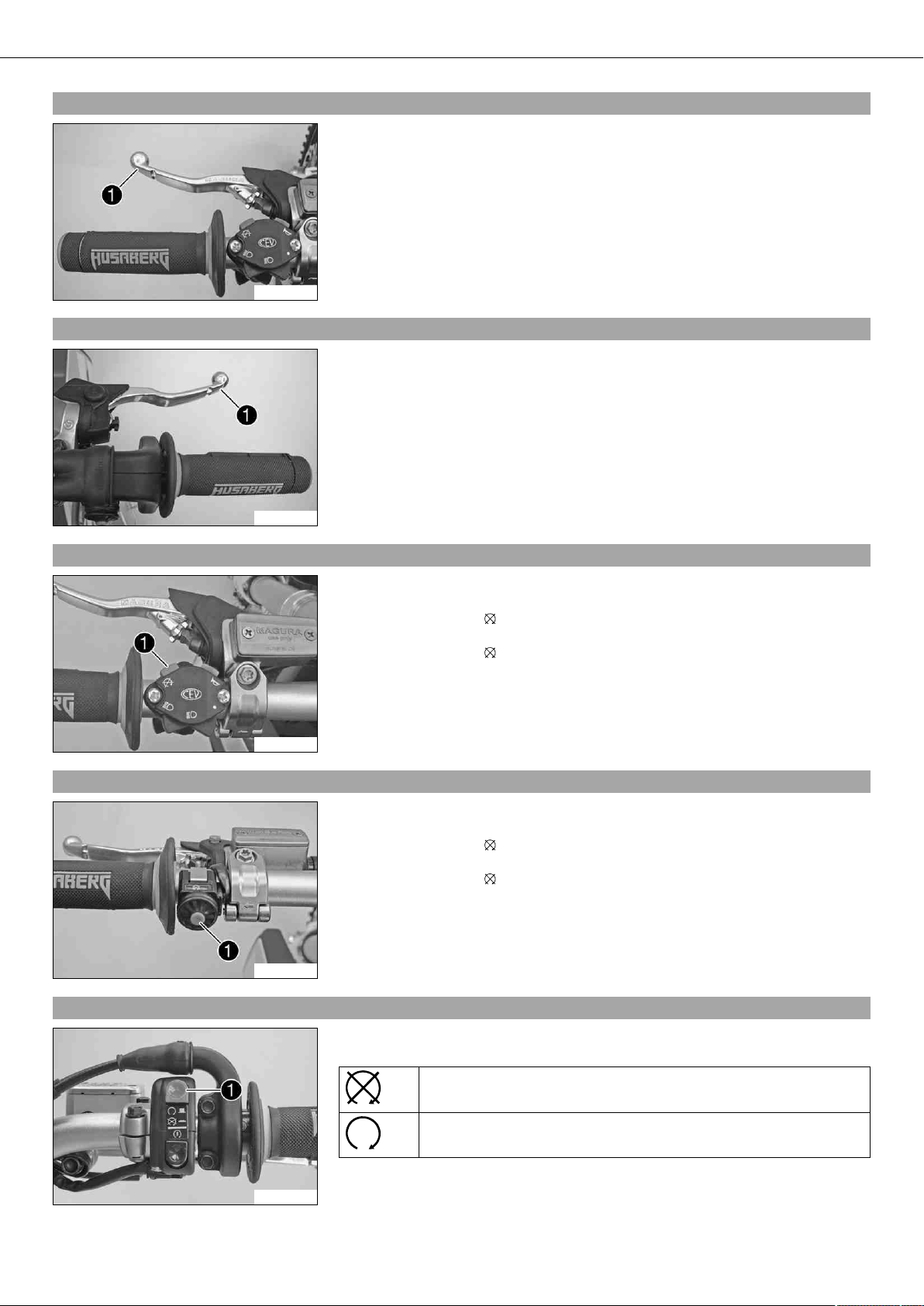
5.10Flasher switch (FE EU, FE AUS)
100357-10
Flasher switch is fitted on the left side of the handlebar.
Possible states
Flasher light off – Flasher switch is in the central position.
Flasher light, left, on – Flasher switch turned to the left.
Flasher light, right, on – Flasher switch turned to the right.
CONTROLS 13
5.11Overview of indicator lamps (FE EU, FE AUS)
Possible states
High beam indicator lamp lights up blue – High beam is switched on.
Flasher indicator lamp flashes green – Flasher light is switched on.
FI warning lamp (MIL) lights up/flashes orange – The OBD has detected
an emission- or safety-critical error.
100358-01
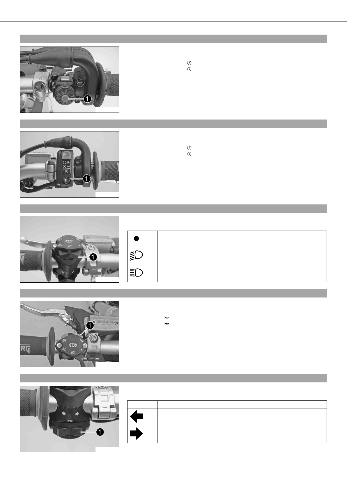
5.12Overview of indicator lamps (FE USA)
Possible states
warning lamp (MIL) lights up/flashes orange – The OBD has detected
FI
an emission- or safety-critical error.
100367-01
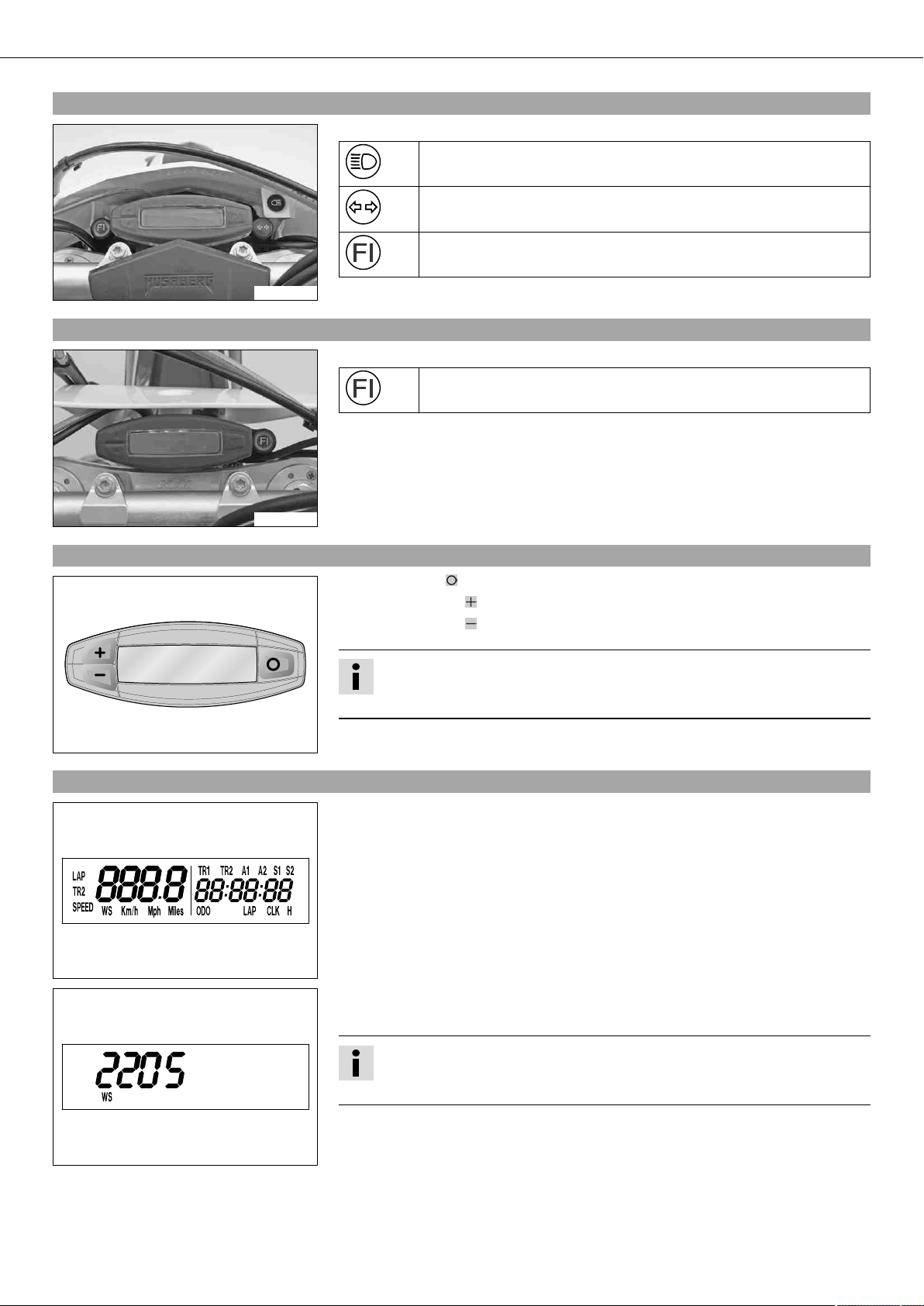
5.13Speedometer
400312-01
5.14Speedometer activation and test
– Press the key to change the display mode or change to one of the setup menus.
– Press the button to control different functions.
– Press the button to control different functions.
Info
In its condition at delivery, the display mode SPEED/H and SPEED/ODO is activated.
Activating the speedometer:
The speedometer is activated when one of the keys is pressed or an impulse comes
from the wheel speed sensor.
Display test
For the function test of the display, all display segments light up briefly.
400313-01
400314-01
WS (wheel size)
After the display function test, the wheel size WS is displayed briefly.
Info
2205 mm corresponds to the size of the 21" front wheel with a series production tire.
The display then changes to the last selected mode.
CONTROLS 14
5.15Tripmaster switch
(Option: Tripmaster switch)
You can use the trip master switch to control the functions of the speedometer from the handlebar.
Info
The trip master is an optional accessory.
5.16Setting kilometers or miles
Info
If you change the unit, the value ODO is retained and converted accordingly.
The values TR1, TR2, A1, A2 and S1 are cleared when the unit of measure is changed.
Condition
The motorcycle is standing.
– Press the button briefly and repeatedly until H appears at the bottom right of the
display.
– Press the button for 3 - 5 seconds.
The Setup menu opens and the active functions are displayed.
– Press the button repeatedly until the Km/h/Mph display flashes.
Km/hadjusting
– Press the button .
Mphadjusting
400329-01
– Press the button .
– Press the button for 3 - 5 seconds.
The settings are saved and the Setup menu closed.
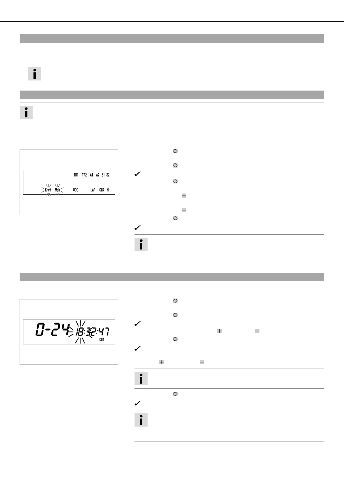
5.17Setting the clock
400330-01
Info
If no button is pressed for 20 seconds, or if no impulse comes from the
wheel speed sensor, the settings are automatically saved and the Setup
menu closed.
Condition
The motorcycle is standing.
– Press the button briefly and repeatedly until CLK appears at the bottom right of
the display.
– Press the button for 3 - 5 seconds.
The hour display flashes.
– Set the hour display with the button and/or button .
– Press the button briefly.
The next segment of the display flashes and can be set.
– You can set the following segments in the same way as the hours by pressing
the button and the button .
Info
The seconds can only be set to zero.
– Press the button for 3 - 5 seconds.
The settings are saved and the Setup menu closed.
Info
If no button is pressed for 20 seconds, or if no impulse comes from the
wheel speed sensor, the settings are automatically saved and the Setup
menu closed.
CONTROLS 15
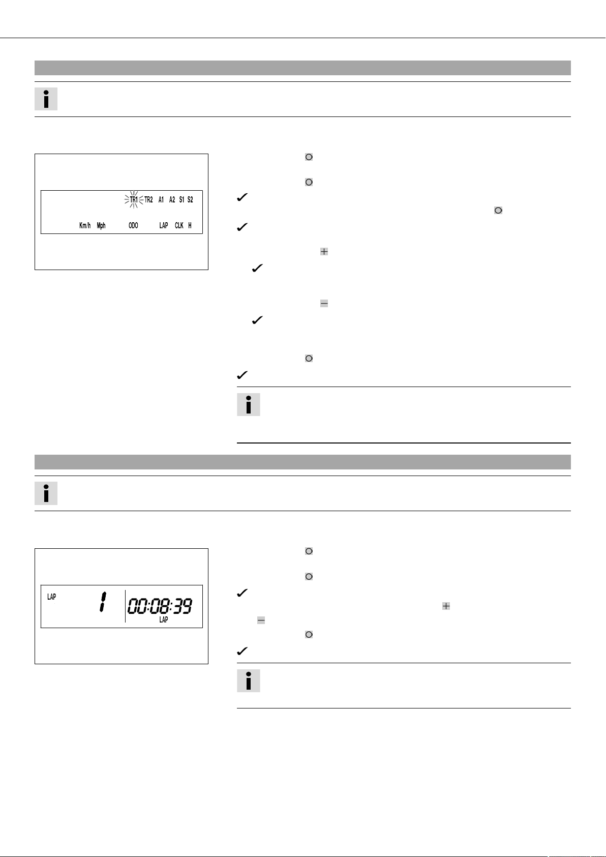
5.18Adjusting the speedometer functions
Info
Upon delivery, only the SPEED/H and SPEED/ODO display modes are activated.
Condition
The motorcycle is standing.
– Press the button briefly and repeatedly until H appears at the bottom right of the
display.
– Press the button for 3 - 5 seconds.
The Setup menu opens and the active functions are displayed.
– Switch to the function you require by briefly pressing the button .
The selected function flashes.
Activating a function
– Press the button .
400318-01
Deactivating a function
– Press the button .
– Activate or deactivate all functions accordingly.
– Press the button for 3 - 5 seconds.
The icon remains in the display and the display changes to the next function.
The icon disappears from the display and the display changes to the next
function.
The settings are saved and the Setup menu closed.
5.19Querying the lap time
Info
This function can be called only if lap times are measured.
Condition
The motorcycle is standing.
– Press the button briefly and repeatedly until LAP appears at the bottom right of
the display.
– Press the button briefly.
– Laps 1-10 can be displayed by pressing the button .
– The button has no function
– Press the button briefly.
400321-01
Info
If no button is pressed for 20 seconds, or if no impulse comes from the
wheel speed sensor, the settings are automatically saved and the Setup
menu is closed.
LAP 1 appears on the left side of the display.
Next display mode
Info
If an impulse is received from the wheel speed sensor, the left side of the
display changes back to the SPEED mode.
CONTROLS 16
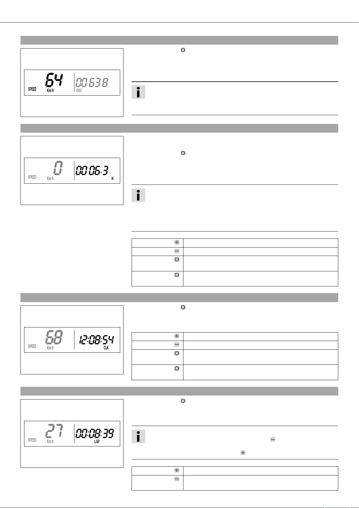
5.20SPEED display mode (speed)
– Press the button briefly and repeatedly until SPEED appears on the left side of
the display.
The current speed is displayed in the SPEED display mode.
The current speed can be displayed in Km/h or Mph.
Info
Making the setting according to the country.
When an impulse comes from the front wheel, the left side of the speedometer
400317-02
5.21SPEED/H display mode (service hours)
400316-01
display changes to the SPEED mode and the current speed is shown.
Condition
• Vehicle at a standstill
– Press the button briefly and repeatedly until H appears at the bottom right of the
display.
The number of service hours of the engine is shown in the H display mode.
The service hour counter stores the total traveling time.
Info
The service hour counter is necessary for ensuring that maintenance work is carried out at the right intervals.
If the speedometer is in the H display mode at the start of the trip, it automatically changes to the ODO display mode.
The H display mode is suppressed during travel.
5.22SPEED/CLK display mode (time)
400319-01
5.23SPEED/LAP display mode (lap time)
Press the button . No function
Press the button . No function
Press the button
for 3 - 5 seconds.
Press the button
The display changes to the Setup menu of the speedometer
functions.
next display mode
briefly.
– Press the button briefly and repeatedly until CLK appears at the bottom right of
the display.
The time is displayed in the CLK display mode.
Press the button . No function
Press the button . No function
Press the button
The display changes to the Setup menu of the clock.
for 3 - 5 seconds.
Press the button
next display mode
briefly.
– Press the button briefly and repeatedly until LAP appears at the bottom right of
the display.
In the LAP display mode, up to ten laps can be timed with the stop watch.
400320-01
Info
If the lap time continues after you press the button , 9 memory locations are
already occupied.
Lap 10 must be timed with the button .
Press the button . Starts or stops the clock.
Press the button . Stops the current lap time and saves it, and the stop watch
starts the next lap.

CONTROLS 17
5.24SPEED/ODO display mode (odometer)
400317-01
5.25SPEED/TR1 display mode (trip master 1)
Press the button
The stop watch and the lap time are reset.
for 3 - 5 seconds.
Press the button
next display mode
briefly.
– Press the button briefly and repeatedly until ODO appears at the bottom right of
the display.
The total number of kilometers ridden is shown in the ODO display mode.
Press the button . No function
Press the button . No function
Press the button
–
for 3 - 5 seconds.
Press the button
next display mode
briefly.
– Press the button briefly and repeatedly until TR1 appears at the top right of the
display.
TR1 (trip master 1) runs constantly and counts to 999.9.
You can use it to measure trips or the distance between refueling stops.
TR1 is coupled with A1 (average speed 1) and S1 (stop watch 1).
400323-01
5.26SPEED/TR2 display mode (trip master 2)
400324-01
Info
If 999.9 is exceeded, the values of TR1, A1 and S1 are automatically reset to
0.0.
Press the button . No function
Press the button . No function
Press the button
The TR1, A1 and S1 displays are reset to 0.0.
for 3 - 5 seconds.
Press the button
next display mode
briefly.
– Press the button briefly and repeatedly until TR2 appears at the top right of the
display.
TR2 (trip master 2) runs constantly and counts to 999.9.
The displayed value can be set manually with the button and the button . A very
practical function for rides by the road book.
Info
The TR2 value can also be corrected manually during the trip using the button and the button .
If 999.9 is exceeded, TR2 is automatically reset to 0.0.
Press the button . Increases value TR2.
Press the button . Decreases value TR2.
Press the button
Clears value TR2.
for 3 - 5 seconds.
Press the button
next display mode
briefly.
CONTROLS 18
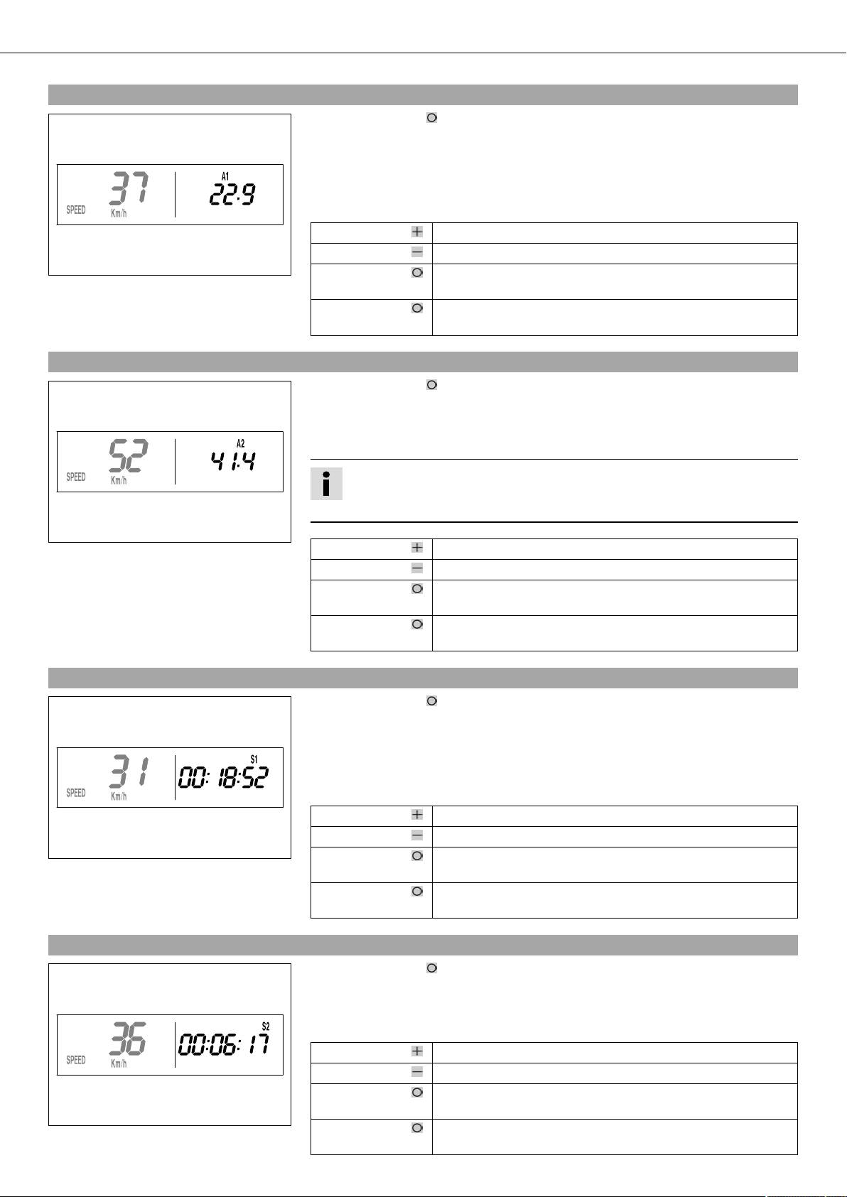
5.27SPEED/A1 display mode (average speed 1)
– Press the button briefly and repeatedly until A1 appears at the top right of the
display.
A1 (average speed 1) shows the average speed calculated on the basis of TR1 (trip master 1) and S1 (stop watch 1).
The calculation of this value is activated by the first impulse of the wheel speed sensor
and ends 3 seconds after the last impulse.
Press the button . No function
400325-01
5.28SPEED/A2 display mode (average speed 2)
Press the button . No function
Press the button
The TR1, A1 and S1 displays are reset to 0.0.
for 3 - 5 seconds.
Press the button
next display mode
briefly.
– Press the button briefly and repeatedly until A2 appears at the top right of the
display.
A2 (average speed 2) shows the average speed on the basis of the current speed if the
stop watch S2 (stop watch 2) is running.
400326-01
5.29SPEED/S1 display mode (stop watch 1)
400327-01
Info
The displayed value can differ from the actual average speed if S2 is not
stopped after the ride.
Press the button . No function
Press the button . No function
Press the button
for 3 - 5 seconds.
Press the button
briefly.
– Press the button briefly and repeatedly until S1 appears at the top right of the
display.
S1 (stop watch 1) shows the trip time on the basis of TR1 and continues running when
an impulse is received from the wheel speed sensor.
The calculation of this value starts with the first impulse of the wheel speed sensor and
ends three seconds after the last impulse.
Press the button . No function
Press the button . No function
Press the button
for 3 - 5 seconds.
Press the button
briefly.
–
next display mode
The TR1, A1 and S1 displays are reset to 0.0.
next display mode
5.30SPEED/S2 display mode (stop watch 2)
400328-01
– Press the button briefly and repeatedly until S2 appears at the top right of the
display.
S2 (stop watch 2) is a manual stop watch.
If S2 is running in the background, the S2 display flashes in the speedometer display.
Press the button . Starts or stops S2.
Press the button . No function
Press the button
The S2 and A2 displays are reset to 0.0.
for 3 - 5 seconds.
Press the button
next display mode
briefly.
CONTROLS 19
Table of functions
Display Press the button . Press the button . Press the button for 3 -
5 seconds.
SPEED/H display mode
(service hours)
No function No function The display changes to
the Setup menu of the
speedometer functions.
SPEED/CLK display mode
(time)
No function No function The display changes to
the Setup menu of the
clock.
SPEED/LAP display mode
(lap time)
Starts or stops the
clock.
Stops the current lap
time and saves it, and
The stop watch and the
lap time are reset.
the stop watch starts
the next lap.
SPEED/ODO display mode
No function No function – next display mode
(odometer)
SPEED/TR1 display mode
(trip master 1)
SPEED/TR2 display mode
No function No function The TR1, A1 and S1 dis-
plays are reset to 0.0.
Increases value TR2. Decreases value TR2. Clears value TR2. next display mode
(trip master 2)
SPEED/A1 display mode
(average speed 1)
SPEED/A2 display mode
No function No function The TR1, A1 and S1 dis-
plays are reset to 0.0.
No function No function – next display mode
(average speed 2)
SPEED/S1 display mode
(stop watch 1)
SPEED/S2 display mode
(stop watch 2)
No function No function The TR1, A1 and S1 dis-
plays are reset to 0.0.
Starts or stops S2. No function The S2 and A2 displays
are reset to 0.0.
Press the button
briefly.
next display mode
next display mode
next display mode
next display mode
next display mode
next display mode
next display mode
Table of conditions and activability
Display Vehicle at a stand-
still
Menu can be activated
SPEED/H display mode (service hours) •
SPEED/CLK display mode (time) •
SPEED/LAP display mode (lap time) •
SPEED/TR1 display mode (trip master 1) •
SPEED/TR2 display mode (trip master 2) •
SPEED/A1 display mode (average speed 1) •
SPEED/A2 display mode (average speed 2) •
SPEED/S1 display mode (stop watch 1) •
SPEED/S2 display mode (stop watch 2) •
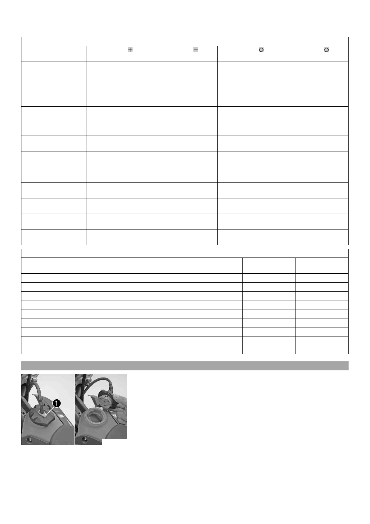
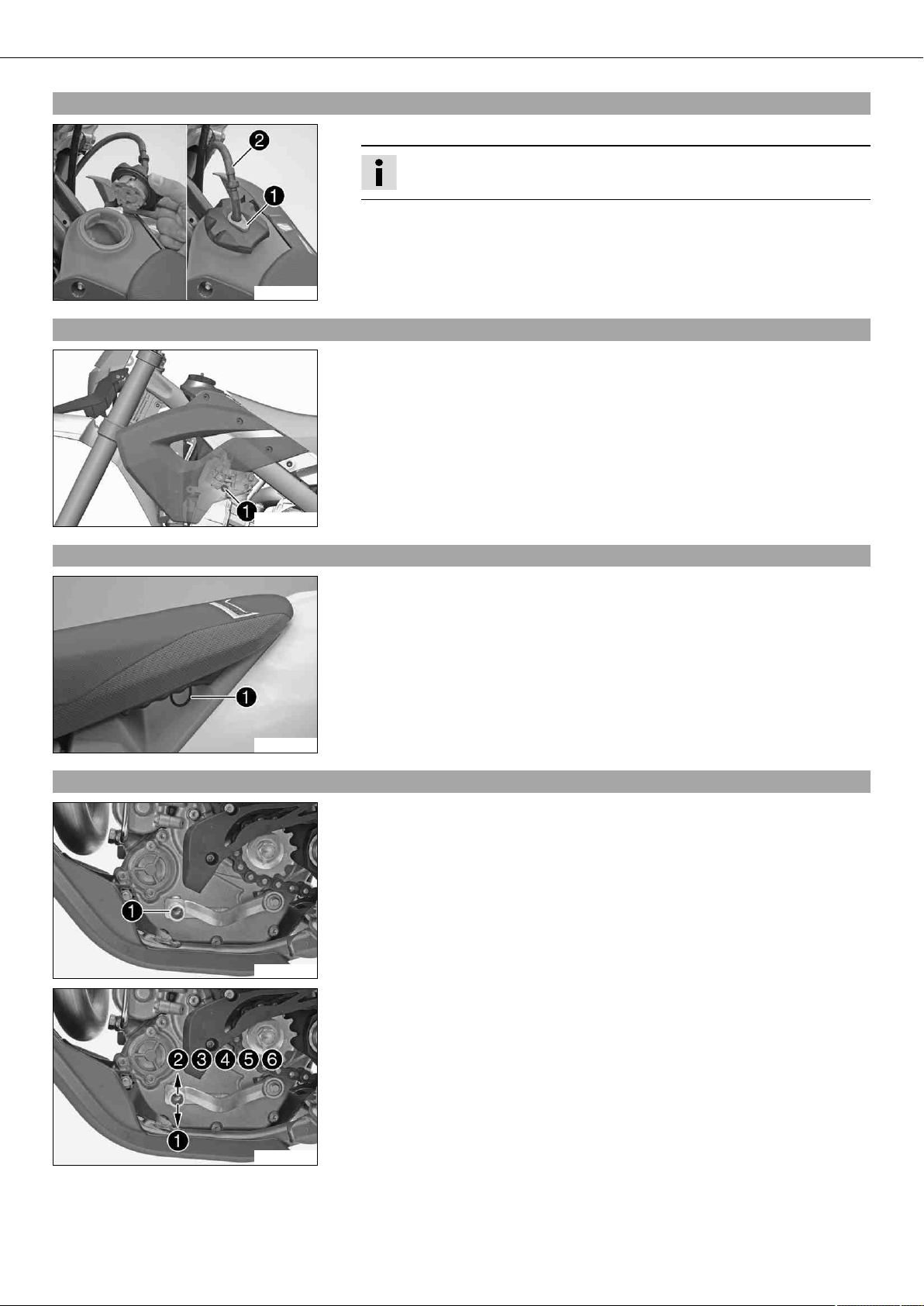
5.31Opening the filler cap
– Press release button , turn filler cap counterclockwise and lift it free.
100359-10
CONTROLS 20
5.32Closing the filler cap
– Replace the filler cap and turn clockwise until the release button locks in place.
Info
Run the fuel tank breather hose without kinks.
100360-10
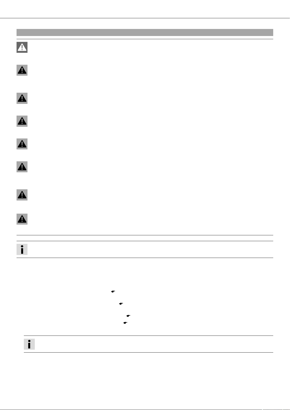
5.33Idle speed adjusting screw
Idle speed adjusting screw is attached to the throttle valve body on the left side.
The idle speed adjusting screw has two functions.
Turning it controls the idle speed.
Pulling it out all the way raises the idle speed during a cold start.
Possible states
• RPM increase activated – Idle speed adjusting screw is pulled out all the way.
• RPM increase deactivated – Idle speed adjusting screw is pushed in all the way.
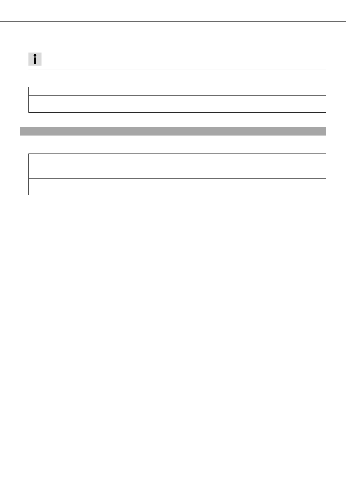
5.34Seat release
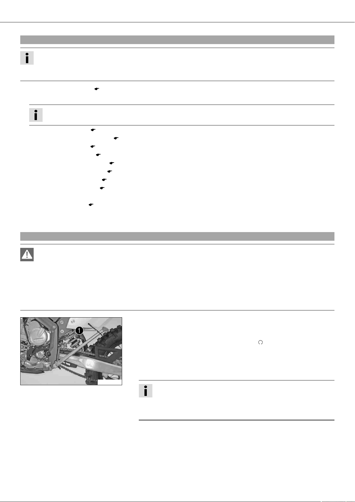
5.35Shift lever
400529-10
The seat can be released by pulling on loop .
100362-10
Shift lever is mounted on the left side of the engine.
100363-10
100363-11
The gear positions can be seen in the photograph.
The neutral or idle position is between the first and second gears.

CONTROLS 21
5.36Foot brake pedal
Foot brake pedal is located in front of the right footrest.
The foot brake pedal is used to activate the rear brake.
100368-10
5.37Side stand
Note
Danger of damage The parked vehicle can roll away or fall over.
– Always place the vehicle on a firm and even surface.
Note
Material damage Damage and destruction of components by excessive load.
– The side stand is designed for the weight of the motorcycle only. Do not sit on the
100369-10
motorcycle when it is supported by the side stand only. The side stand and/or the
frame could be damaged and the motorcycle could fall over.
5.38Steering lock (FE EU, FE AUS)
To park the motorcycle, press side stand to the ground with your foot and lean the
motorcycle on it.
When you are riding, side stand must be folded up and secured with rubber
band .
100370-10
Steering lock is fitted on the left side of the steering head.
The steering lock is used to lock the steering. Steering, and therefore riding, is no
longer possible.
100371-10
5.39Locking the steering (FE EU, FE AUS)
Note
Danger of damage The parked vehicle can roll away or fall over.
– Always place the vehicle on a firm and even surface.
– Park the motorcycle.
– Turn the handlebar as far as possible to the right.

CONTROLS 22
– Insert the key in the steering lock, turn it to the left, press it in and turn it to the right. Remove the key.
Steering is no longer possible.
Info
Never leave the key in the steering lock.
5.40Unlocking the steering (FE EU, FE AUS)
– Insert the key in the steering lock, turn it to the left, pull it out and turn it to the right. Remove the key.
You can now steer the bike again.
Info
Never leave the key in the steering lock.
GENERAL TIPS AND HINTS ON PUTTING INTO OPERATION 23
6.1Advice on first use
Danger
Danger of accidents Danger from insufficient traffic competence.
– Do not use the vehicle if you are not fit to deal with traffic or if you have consumed alcohol and/or medicaments or drugs.
Warning
Risk of injury Missing or insufficient protective clothing increases the risk of injury.
– Wear protective clothing (helmet, boots, gloves, pants and jacket with protectors) every time you ride the vehicle. Always
wear protective clothing, which must be in perfect condition and meet legal requirements.
Warning
Danger of crashing Impairment of riding behavior due to different tire tread patterns on front and rear wheels.
– The front and rear wheels must be fitted with tires with similar tread patterns to prevent loss of control over the vehicle.
Warning
Danger of accidents Critical riding behavior due to inappropriate riding.
– Adapt your riding speed to the road conditions and your riding ability.
Warning
Danger of accidents Accident risk caused by presence of a passenger.
– Your vehicle is not designed to carry passengers. Do not ride with a passenger.
Warning
Danger of accidents Brake system failure.
– If the foot brake pedal is not released, the brake linings drag permanently. The rear brake can fail due to overheating. Take
your foot off the foot brake pedal if you do not want to brake.
Warning
Danger of accidents Unstable riding behavior.
– Do not exceed the maximum permitted weight and axle loads.
Warning
Risk of misappropriation Usage by unauthorized persons.
– Never leave the vehicle while the engine is running. Secure the vehicle against use by unauthorized persons.
Info
When using your motorcycle, remember that others may feel disturbed by excessive noise.
– Make sure that the pre-delivery inspection work has been carried out by an authorized HUSABERG workshop.
You receive a delivery certificate and the service record at vehicle handover.
– Before your first trip, read the entire operating instructions carefully.
– Get to know the controls.
– Adjust the basic position of the clutch lever. ( p. 69)
(FE EU, FE AUS)
– Adjust the free travel of the handbrake lever. ( p. 46)
(FE USA)
– Adjust the basic position of the handbrake lever. ( p. 45)
–
Adjust the basic position of the footbrake lever. x ( p. 49)
– Get used to handling the motorcycle on a suitable piece of land before making a longer trip.
Info
Offroad, you should be accompanied by another person on another machine so that you can help each other.
– Try also to ride as slowly as possible and in a standing position to get a better feeling for the vehicle.
– Do not make any offroad trips that over-stress your ability and experience.
– Hold the handlebar firmly with both hands and keep your feet on the footrests when riding.
GENERAL TIPS AND HINTS ON PUTTING INTO OPERATION 24
– If you carry any baggage, make sure it is fixed firmly as close as possible to the center of the vehicle and ensure even weight dis-
tribution between the front and rear wheels.
Info
Motorcycles react sensitively to any changes of weight distribution.
– Do not exceed the overall maximum permitted weight and the axle loads.
Guideline
Maximum permissible overall weight 335 kg (739 lb.)
Maximum permissible front axle load 145 kg (320 lb.)
Maximum permissible rear axle load 190 kg (419 lb.)
– Run the engine in.
6.2Running in the engine
– During the running-in phase, do not exceed the specified engine speed and engine performance.
Guideline
Maximum engine speed
During the first 3 service hours 7,000 rpm
Maximum engine performance
During the first 3 service hours ≤ 50 %
During the next 12 service hours ≤ 75 %
– Avoid fully opening the throttle!
RIDING INSTRUCTIONS 25
7.1Checks before putting into operation
Info
Make sure that the motorcycle is in a perfect technical condition before use.
In the interests of riding safety, make a habit of making a general check before you ride.
Note that the fuel tank does not indicate fuel reserves.
– Check the engine oil level. ( p. 71)
– Check the fuel reserves.
Info
There is no fuel reserve.
– Check the chain tension. ( p. 42)
– Check for chain dirt accumulation. ( p. 42)
– Check the tire condition. ( p. 55)
– Check the tire air pressure. ( p. 55)
– Check the front brake fluid level. ( p. 46)
– Check the rear brake fluid level. ( p. 50)
– Check the front brake linings. ( p. 47)
– Check the rear brake linings. ( p. 51)
– Check the brake system function.
– Check the coolant level. ( p. 67)
– Check the settings of all controls and ensure that they can be operated smoothly.
– Check the functioning of the electrical equipment.
7.2Starting
Danger
Danger of poisoning Exhaust gases are poisonous and can result in unconsciousness and/or death.
– When running the engine, always make sure there is sufficient ventilation, and do not start or run the engine in a closed
space without an effective exhaust extraction system.
Note
Engine failure High engine speeds in cold engines have a negative effect on the service life of the engine.
– Always warm up the engine at low engine speeds.
– Raise the motorcycle off of the stand and secure the stand with rubber band .
– Shift gear to neutral.
(FE AUS)
– Turn the emergency OFF switch to the position .
Condition
Ambient temperature: < 20 °C (< 68 °F)
– Pull the idle speed adjusting screw all the way out.
– Press the electric starter button.
100370-11
Info
Do not open the throttle to start.
Press the starter for a maximum of 5 seconds. Wait for a least 5 seconds
until trying again.
Warning lamp FI lights up briefly as a functional control when starting.
RIDING INSTRUCTIONS 26
7.3Starting up
Info
If your bike has lights, switch them on before riding. You will then be seen earlier by other motorists.
When you are riding, the side stand must be folded up and secured with the rubber band.
– Pull the clutch lever, engage 1st gear, release the clutch lever slowly and simultaneously open the throttle carefully.
7.4Shifting, riding
Warning
Danger of accidents An abrupt load alterations can cause the vehicle to get out of control.
– Avoid abrupt load alterations and sudden braking actions, and adapt your speed to the road conditions.
Warning
Danger of accidents If you change down at high engine speed, the rear wheel can lock up.
– Do not change into a low gear at high engine speed. The engine races and the rear wheel can block.
Warning
Danger of accidents Distraction from traffic activity by adjustments to the vehicle.
– Make all adjustments when the vehicle is at a standstill.
Warning
Danger of accidents After a fall, check the vehicle.
– After a fall, check the vehicle as usual before putting it into operation.
Note
Engine failure Unfiltered intake air has a negative effect on the service life of the engine.
– Never ride the vehicle without an air filter since dust and dirt can get into the engine and result in increased wear.
Info
If you hear unusual noises while riding, stop immediately, switch off the engine and contact an authorized HUSABERG workshop.
First gear is used for starting off or for steep inclines.
Tip
On difficult terrain, an increased idle speed prevents the engine from stalling unintentionally.
– When conditions allow (incline, road situation, etc.), you can shift into a higher gear. To do so, release the throttle while simulta-
neously pulling the clutch lever, shift into the next gear, release the clutch and open the throttle.
– If you raised the idle speed to start the vehicle, push the idle speed adjusting screw in all the way after the engine warms up.
– When you reach maximum speed after fully opening the throttle, turn back the throttle to about 3/4 of its range. This barely
reduces vehicle speed but lowers fuel consumption considerably.
– Always open the throttle only as much as the engine can handle – abrupt throttle opening increases fuel consumption.
– To shift down, brake and close the throttle at the same time.
– Pull the clutch lever and shift into a lower gear, release the clutch lever slowly and open the throttle or shift again.
– Switch off the engine if you expect to be standing for a long time.
Guideline
≥ 2 min
– Avoid frequent and longer slipping of the clutch. This heats the engine oil, the engine and the cooling system.
– Ride with a lower engine speed instead of with a high engine speed and a slipping clutch.
– If the FI warning lamp (MIL) starts to light up during the trip, stop immediately. When the engine reaches idle speed, the FI warn-
ing lamp (MIL) starts flashing.
Info
From the flash rhythm you can deduce a two-digit number, the so-called flash code. The flash code tells you which component is affected by a fault.
RIDING INSTRUCTIONS 27
7.5Stopping, parking
Warning
Risk of misappropriation Usage by unauthorized persons.
– Never leave the vehicle while the engine is running. Secure the vehicle against use by unauthorized persons.
Warning
Danger of burns Some vehicle components get very hot when the machine is driven.
– Do not touch hot components such as exhaust system, radiator, engine, shock absorber and brakes. Allow these compo-
nents to cool down before starting work on them.
Note
Danger of damage The parked vehicle can roll away or fall over.
– Always place the vehicle on a firm and even surface.
Note
Fire hazard Some vehicle components get very hot when the machine is driven.
– Do not place the vehicle where there are flammable or explosive substances. Do not place objects over the vehicle while it is still
warm from being run. Always let the vehicle cool first.
Note
Material damage Damage and destruction of components by excessive load.
– The side stand is designed for the weight of the motorcycle only. Do not sit on the motorcycle when it is supported by the side
stand only. The side stand and/or the frame could be damaged and the motorcycle could fall over.
– Brake the motorcycle.
– Shift gear to neutral.
(FE USA)
– Press and hold the short circuit button while the engine is idling until the engine stops.
(FE EU, FE AUS)
– Press and hold the short circuit button while the engine is idling until the engine stops.
– Park the motorcycle on firm ground.
7.6Refueling
Danger
Fire hazard Fuel can easily catch fire.
– Never fill up the vehicle near open flames or burning cigarettes, and always switch off the engine first. Be careful that no
fuel is spilt, especially on hot vehicle components. Clean up spilt fuel immediately.
– Fuel in the fuel tank expands when warm and can escape if the tank is overfilled. See specifications on filling up with fuel.
Warning
Danger of poisoning Fuel is poisonous and a health hazard.
– Avoid contact between fuel and skin, eyes and clothing. Do not inhale fuel vapors. If fuel gets into your eyes, rinse imme-
diately with water and contact a doctor. Wash affected skin areas immediately with soap and water. If fuel is swallowed,
contact a doctor immediately. Change clothing that has come into contact with fuel.
Warning
Environmental hazard Improper handling of fuel is a danger to the environment.
– Do not allow fuel to get into the ground water, the ground, or the sewage system.
– Switch off the engine.
– Open the filler cap. ( p. 19)
RIDING INSTRUCTIONS 28
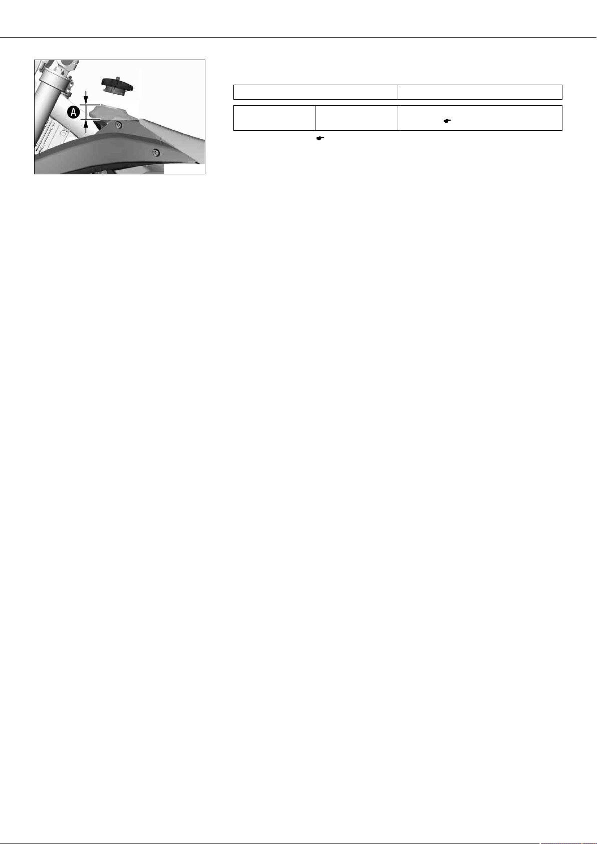
– Fill the fuel tank with fuel up to measurement .
Guideline
Measurement of 35 mm (1.38 in)
400515-10
Total fuel tank
capacity, approx.
– Close the filler cap. ( p. 20)
8.2 l
(2.17 US gal)
Super unleaded (ROZ 95 / RON 95 /
PON 91) ( p. 92)