

Page 1
INDEX
INTRODUCTION Page 2-
SAFETY AND PRECAUTIONS Page 4-
GENERAL INFORMATION Page 6-
MAINTENANCE SCHEDULE Page 9-
CONTROLS Page 12-
1
2
3
4
5
STARTING PROCEDURE Page 15
ENGINE Page 16-
FUEL & COOLING Page 20-
CLUTCH & DECOMPRESSION Page 22
WHEELS & BRAKES Page 23-
A LUBRICATION SYSTEM
B IGNITION
C AIR FILTER
D VALVE ADJUSTMENT
A CARBURETTOR
B FUEL
C COOLING SYSTEM
A WHEELS
B CHAIN
C BRAKES
6
7
8
9
10
SUSPENSION Page 29-
WIRING DIAGRAMS Page 33-
A SUSPENSION
B STEERING HEAD
C SWINGARM
11
12
1
Page 2
1
INTRODUCTION
1
Please read and observe the following:
Warning
If the engine has to be running during any maintenance, make sure that the area is
properly ventilated. Never run the engine in a closed area though the exhaust fumes
are posionous and thus hazardous to your health and life.
Warning
Although the battery is of a sealed construction, please take care. The electrolyte contains
sulfuric acid and you must protect your eyes, skin and clothing if such fluid is assumed
to be leaking or likewise exposed. In case of contact, wash and flush thoroughly with
water and contact medical help if needed, especially if your eyes have been exposed to
the fluid.
Warning
Fuel is extremely flammable and explosive under certain conditions. Do not smoke or
expose the fuel to open fire or sparks.
SERVICE CONDITIONS:
1. Always use original Husaberg parts.
2. Use the special Husaberg tools when required.
3. Install new gaskets, o-rings, circlips etc whenever possible.
4. Always clean all parts thoroughly before assembly.
5. All screws, nuts and bolts etc. are in the metric system. Do not use incorrect tools.
PRINT & COPY RIGHTS
The material and information included in this Owner’s Manual are all of the latest editions
available at the time of the printing.
Husaberg Motor AB reserves the right to make changes regarding the products at any
time without prior notice.
This Owner’s Manual is subject to corrections without prior notice.
No part of this Owner’s Manual may be reproduced without written permission
Endurovägen, S-695 72 SWEDEN
www.husaberg.se
2
Page 3
1
INTRODUCTION
Dear client,
We feel ourselves privileged and honoured to be the supplier of your choice of motorcycle. We
know for sure that our product will give you years of fun and performance though the Husabergs
are based upon decades of experience in racing and a dedication hard to find elsewere. You’re
bound to feel this through the inborn lively spirit of your bike.
Although mainly designed and constructed for competition purposes it is still very rider-friendly
but due to the design the product needs careful and proper maintenannce. In order to get the
most out of your "beast" and before any use of the motorbike; we highly recommend you to
carefully read this Owner's Manual through. We also recommend you to pay your outmost
attention to the following page regarding safety and precautions and always remember the
fundamental base of all activities on two wheels:
- "Do not overestimate your capabilities, follow the domestic regulations and do think about
your surroundings"
Although the Owner's Manual is put together and written in a way that will make it possible for
an average mechanical experienced person to take care of the maintenance, we recommend
you to let an authorized Husaberg dealer take care of at least the parts we’ve mentioned under:
1
Also, part of the maintenance has to be performed by an authorized dealer in order to fulfill the
terms of warranty.
If you follow the advice regarding the set-up and of course also regarding the vital maintenance
of the motorcycle; the Husaberg of yours will provide a maintained level of performance (read:
joy and satisfaction - the reason to your choice of brand).
The personnel of Husaberg Motor AB Sweden
ATTENTION:
ATTENTION:
ATTENTION:
Never ride in a too low or too high gear Never let the engine run for more than one minute while stationary
It may cause severe mechanical damages
Always put the motorcycle on a stable centerstand
whenever removing either front or rear wheel.
Never ride your motorcycle under the influence of
alcohol, drugs, barbiturates or any other kind of medical
treatments hazardous to your riding performance.
WARNING:
Do not check the coolant
level while the engine is hot.
ATTENTION:
Service more frequently when
riding under hard conditions
ATTENTION:
Less clearances than the required
cause severe engine damages
ATTENTION:
Do not use a highpressure jet-cleaning
equipment on surfaces around
bearings and other fragile components.
3
Page 4
2
2
SAFETY AND PRECAUTIONS
SAFETY
PROTECTION:
Always protect yourself with adequat clothing and protective apparel.
Always wear a helmet, goggles and boots.
MOTORCYCLE:
The motorcycle may become dangerous to ride if it is modified or if any other parts than
original Husaberg parts are used. The use of other parts than original makes the warranty
no longer valid.
Always keep your motorcycle in a safe state and in the best of conditions.
Regular cleaning and maintenance are extremely vital in order to avoid any mechanical
damages hazardous to you and/or your surroundings.
TRANSPORTATION:
Always transport your bike upright in order to avoid any leakages of oil and/or fuel. Such
fluids may increase the risk of fire. Always make sure that the bike is properly fastened
in a safe and firm position during transportation.
RIDING:
Always check the motorcycle for any deterioration/damages and any necessary
adjustments before you start the motorcycle (see "Pre-ride inspection").
Though the Husaberg motorcycle has a very high level of performance; always ride
with care and do not overestimate your capabilities. Get to know your Husaberg
motorcycle really well before you try to get the most out of it.
Never lend your motorcycle to any other rider unless you are sure that he/she is fully
capable of handling it.
Always obey all local and federal regulations and laws valid within the territory.
Never ride in terrain unfamiliar to you unless inspected and guaranteed by the local
authorities.
PRE-RIDE INSPECTION:
Make it a habit to give your motorcycle an inspection before and after every ride.
Always check all bolts and nuts and tighten if necessary - All for your own safety.
A clean and well lubricated bike makes for a safer ride as well as a higher value of the
machine. The Pre-ride Inspection Checklist on the next page is to be regarded as a
brief summary of the main important items to be controlled and, if necessary; to be
adjusted or replaced.
Never ride your motorcycle under the influence of
ATTENTION:
4
alcohol, drugs, barbiturates or any other kind of medical
treatments hazardous to your riding performance.
Page 5

2
SAFETY AND PRECAUTIONS
PRE-RIDE INSPECTION CHECK LIST
Engine oil Check the level and fill up if necessary.
Check for any leakages in the casing.
Ignition Check the sparkplug cap/HV lead for damages.
Radiator Check the coolant level and fill up if necessary.
Check for leakages and/or damages of the cells and hoses
and attachments.
Airfilter Clean, or if necessary, replace the filter
Carburettor Check the function of the throttle/cable and adjust/replace
any damaged parts if necessary.
Adjust the idling- and/or mixture screw if necessary.
After every time the motorbike has been washed drain the
float chamber of the carburettor.
2
Clutch Check the function and for any leakages.
Decompression Check the function of the manual and the semi-automatic
decompression lever and adjust if necessary (non-electrical
starter models only).
Chain Check and adjust/replace the chain if necessary.
Check the sprockets and replace if necessary.
Suspension Check the operation of the front fork and the shock absorber
and adjust if necessary.
Check and tighten the swingarm if necessary.
Wheels Check the air pressure of the tyres and fill up if necessary.
Check the spokes and tighten if necessary.
Brakes Check the level of brakefluid and fill up if necessary.
Check for any leakages and the function of the brakes.
Adjust levers and/or replace hoses/pads if necessary.
Fuel Check the level and fill up if necessary.
Check for any leakages in the fuel lines.
Steering Check the clearance of the steering head bearings and
adjust if necessary.
Controls Check the function of the speedometer or odometer (if
incl.in equipment).
Lighting Check the functions of the front-, tail-, and brake lights
(and any occuring turn signals).
5
Page 6
3
3
GENERAL INFORMATION
SPECIFICATIONS
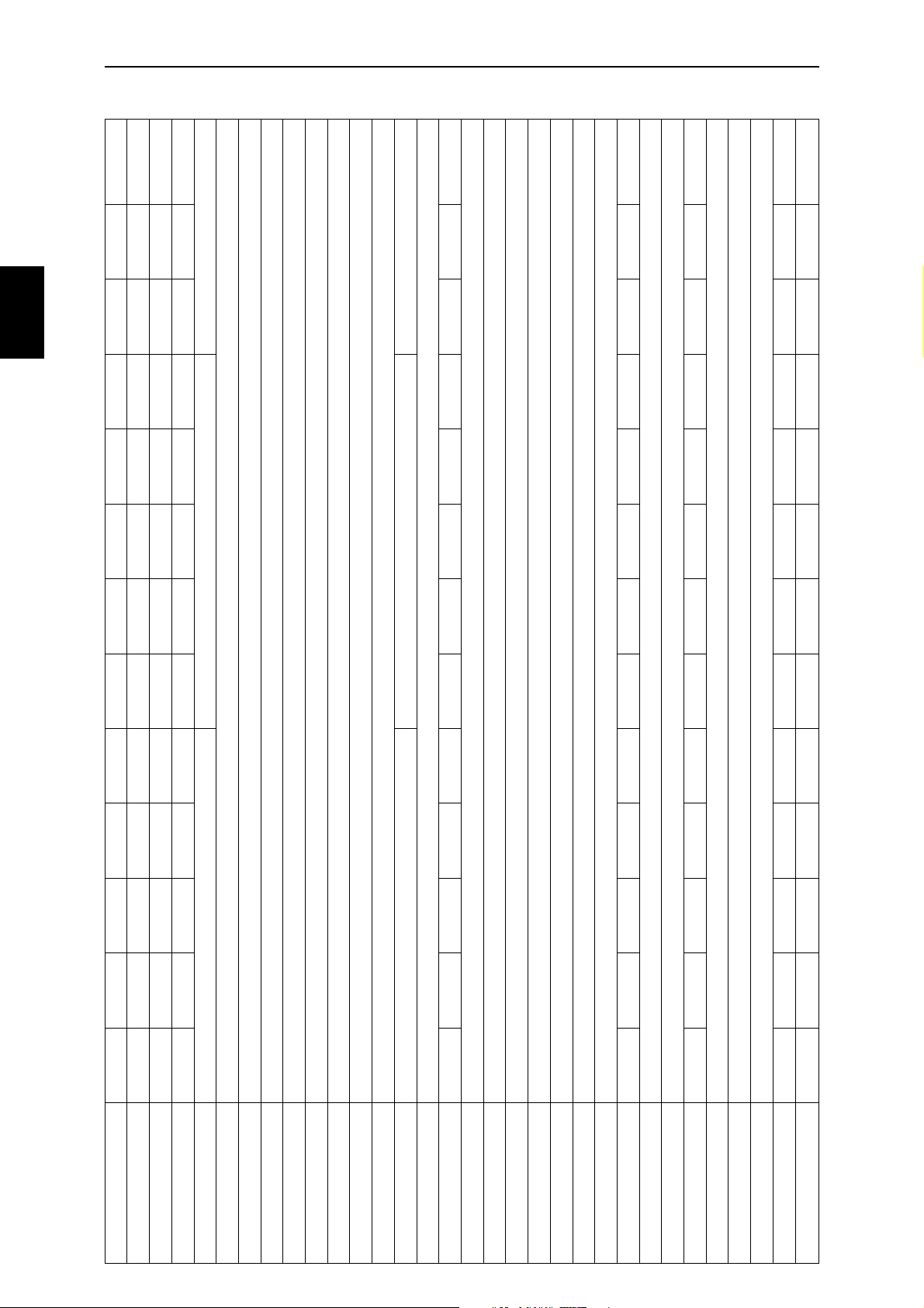
242 lb. 243 lb. 244 lb. 247 lb. 249 lb. 233 lb. 235 lb. 228 lb. 228 lb. 229 lb. 242 lb. 242 lb. 243 lb.
Ratios 1st: 14/33 - 2,357 2nd: 17/30 - 1,765 3rd: 19/26 - 1,368 4th: 23/25 - 1,087 5th: 24/22 - 0,917 6th: 27/20 - 0,741 (6th CR: 25/21-0,840)
SUBJECT/MODEL FE 400 e FE 501 e FE 650 e FS 400 e FS 650 e FS 400 c FS 650 c FC 470/6 FC 550/4 FC 550/6 FC 470 e FX 470 e FX 650 e
Displacement 399cc 501cc 644cc 399cc 644cc 399cc 644cc 472cc 550cc 550cc 472cc 472cc 644cc
Bore x Stroke (mm) 92 x 60,1 95 x 70,7 100 x 82,0 92 x 60,1 100 x 82,0 92 x 60,1 100 x 82,0 100 x 60,1 100 x 70,0 100 x 70,7 100 x 60,1 100 x 60,1 100 x 82,0
Compression ratio 12,5:1 11,8:1 11,0:1 12,5:1 11,0:1 12,5:1 11,0:1 12,4:1 12,7:1 12,7:1 12,4.1 12,4:1 11,0:1
Start system Electrical and kick-starter Kick-starter Electrical and kick-starter
Decompression system Three separate ones; one activated by the kickstart lever, one activated by the camshaft and one activated by a lever on the handlebar
Decomp. cable clearance 2mm ± 1mm / 0,08 in ± 0,04 in.
Engine Liquid cooled single cylinder 4-stroke, SOHC-4 valves, counter balancer
Valve clearance Intake and Exhaust: 0,10mm / 0,004 in.
Lubrication system Orbit oil pump and reed valve controlled. High pressure jet spray of piston and connecting rod, pressure lubrication of connecting rod bearing and rocker arms. Oil screen and micro filter
Engine oil 1,0 Litre Synthetic SAE 5W-50 API SG/CF (minimum SAE 10W-50)
Ignition system SEM Dynamic Force Control, DFC™, Dual Ignition Curves; High & Low. A load sensitive digital system with six sensors
Spark plug - Spark plug gap NGK DCPR8E - 0,6 mm / 0,025 in.
Alternator 12 V 70 + 70 W Not available 12 V 70 + 70 W
Air intake system Single foam filter
Carburettor (DELLORTO) PHM 38 PHM 40 PHM 40 PHM 38 PHM 40 PHM 40 PHM 40 PHM 40 PHM 40 PHM 40 PHM 40 PHM 40 PHM 40
Fuel RON 98 (octane), unleaded
Exhaust system Chrome plated steel pipes, 2 into 1 collector, Aluminium/steel silencer. USA versions, except FC and FSc models, equipped with spark arresters
Coolant 1,3 Litre of 50% Anti-freeze, with corrosion inhibitor, and 50% water
Clutch Hydraulic, 7 friction- and 8 mating plates in oil bath
Clutch hydraulic oil Mineral oil SAE 2-7W
Wear limit clutch discs 19,6 mm / 0,772 in.
Primary transmission Spur gears, ratio 29/78 - 2,690
Gearbox 6-speed 6-speed 6-speed 6-speed 6-speed 6-speed 6-speed 6-speed CR 4-speed 6-speed CR 6-speed CR 6-speed 6-speed
Secondary transmission D.I.D. 520 O-ring chain
Sprockets front/rear 13/48 15/48 15/42 15/42 15/42 15/42 15/42 13/42 15/42 15/48 13/48 13/48 15/42
Wear limit drive chain 272 mm - 18 chain reels (tensioned, center distance between reels)
Frame Heat treated BTR / 25CrMo4 steel
Caster 28,5°
6
Weight (dry) 109,8 kg 110,1 kg 110,9 kg 111,9 kg 113,1 kg 105,7 kg 106,8 kg 103,5 kg 103,5 kg 103,9 kg 109,6 kg 109,6 kg 110,4 kg
Page 7

3
GENERAL INFORMATION
SPECIFICATIONS
3
Rear EXCEL 2.15 x 18” BEHR 4.25 x 17” EXCEL 2.15 x 19” EXCEL 2.15 x 18”
SUBJECT/MODEL FE 400 e FE 501 e FE 650 e FS 400 e FS 650 e FS 400 c FS 650 c FC 470/6 FC 550/4 FC 550/6 FC 470 e FX 470 e FX 650 e
Rims Front EXCEL 1.60 x 21” BEHR 3.50 x 17” EXCEL 1.60 x 21” EXCEL 1.60 x 21”
Rear 140/80-18” 150/60-17” 110/100-19” 130/80-18”
Tyres (MICHELIN)Front 90/90-21” 120/60-17” 80/100-21” 90/90-21”
Tyre pressure (cold)
Rear 0,8 bar / 12,0 psi 0,8 bar / 12,0 psi
Rear 1,0 bar / 14,5 psi 2,0 bar / 29,0 psi
Offroad Front 0,8 bar / 12,0 psi 0,8 bar / 12,0 psi
Tarmac Front 1,0 bar / 14,5 psi 2,2 bar / 31,9 psi
ø 260 mm Inox steel disc ø 310 mm Plated cast iron disc ø 260 mm Inox steel disc
Hydraulic twin piston floating caliper Hydraulic four piston floating caliper Hydraulic twin piston floating caliper
Rear PDS 5018-HBG E PDS 5018-HBG S PDS 5018-HBG MX
Rear 320 mm / 12,6 in. 287 mm / 11,3 in. 320 mm / 12,6 in.
Suspension (WP) Front MXMA 4860-HBG E ø 48 mm MXMA 4860-HBG S ø 48 mm MXMA 4860-HBG MX ø 48 mm
Wheel travel Front 295 mm / 11,6 in. 260 mm / 10,2 in. 295 mm / 11,6 in.
Front fork oil WP SAE 5
Brakes Front BREMBO BERINGER BREMBO
Rear BREMBO hydraulic single piston floating caliper, ø 220 mm Inox steel disc
Brake fluid DOT 4
Alt. B 12 V 45/40 W - BA20d Not applicable
Wear limit brake pads 1,5 mm / 0,06 in.
Head light Alt. A 12 V 65/50 W - P43t Not applicable
Tail / Stop light 12 V 21/5 W - BAY 15d Not applicable
Parking light 12 V 4 W - BA9s Not applicable
Turn signal lights 12 V 10 W - BA15s Not applicable
Speedometer light 12 V 2 W - BA7s Not applicable
Battery / Main fuse 12 V 8 Ah / 15 A Not applicable
Wheel base - Width 1490 mm / 58,66 in. - 810 mm / 31,89 in.
Seat height 930 mm / 36,61 in. 870 mm / 34,25 in. 930 mm / 36,61 in.
Ground clearance 380 mm / 14,96 in. 320 mm / 12,60 in. 380 mm / 14,96 in.
Overall length 2200 mm / 86,61 in. 2150 mm / 84,65 in. 2200 mm / 86,61 in.
7
Page 8
3
GENERAL INFORMATION
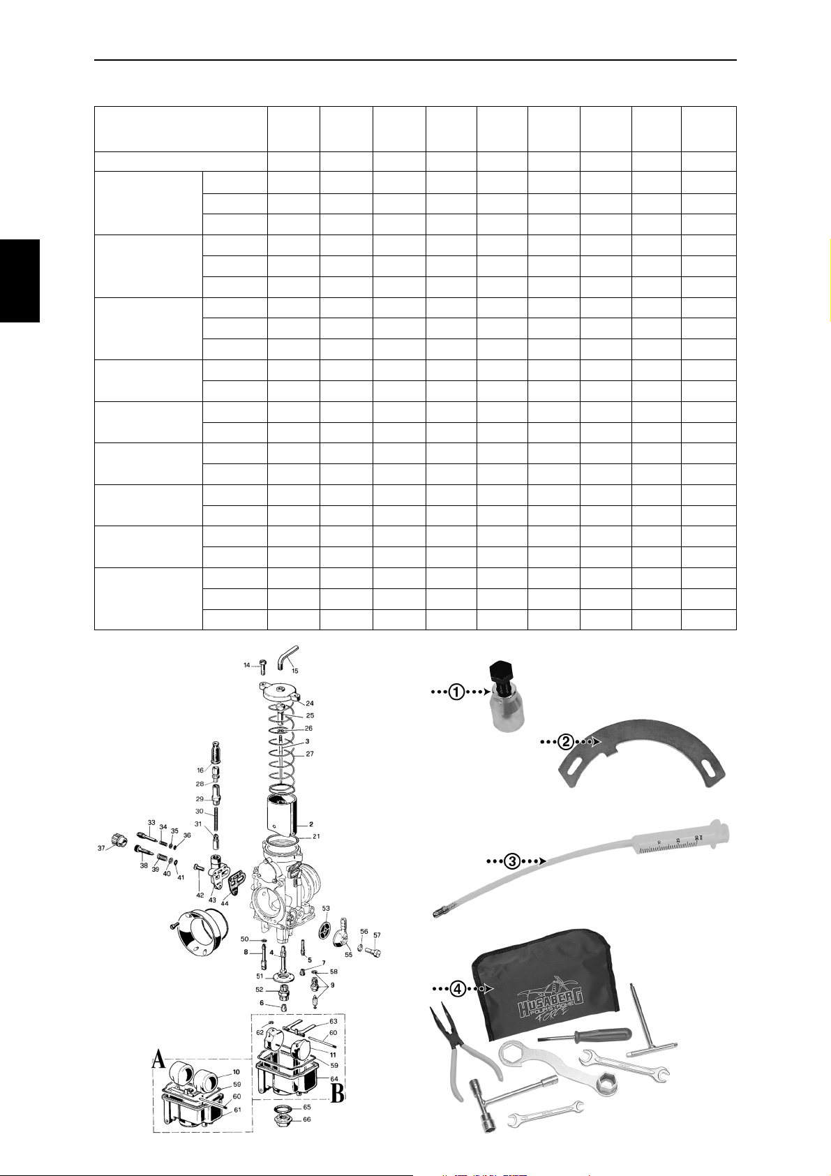
CARBURETTOR STD. JETTINGS
3
MODEL/SUBJECT
Exploded view number
Enduro
Enduro
ECE
Enduro
USA
Super Motard
Street
Super Motard
Street ECE
Super Motard
Street USA
Super Motard
Competition
Cross Country
Motocross
FE 400 e
FE 501 e
FE 650 e
FE 400 e
FE 501 e
FE 650 e
FE 400 e
FE 501 e
FE 650 e
FS 400 e
FS 650 e
FS 400 e
FS 650 e
FS 400 e
FS 650 e
FS 400 c
FS 650 c
FX 470 e
FX 650 e
FC 470
FC 550
FC 470 e
Main
Needle
jet
# 6
185 DR 270 K 51 #3 33 40 300
185 DR 272 K 51 #3 35 40 300
190 DR 272 K 51 #3 40 40 300
110 DR 266 K 51 #2 48 40 300
110 DR 264 K 35 #4 33 40 300
100 DR 266 K 51 #3 33 40 300
190 DR 270 K 51 #3 38 40 300
195 DR 268 K 35 #3 33 40 300
195 DR 270 K 35 #3 33 40 300
185 DR 270 K 51 #3 33 40 300
190 DR 272 K 51 #3 40 40 300
110 DR 266 K 51 #2 48 40 300
100 DR 266 K 51 #3 33 40 300
190 DR 270 K 51 #3 38 40 300
195 DR 270 K 35 #3 33 40 300
180 DR 272 K 35 #3 33 40 300
190 DR 272 K 51 #3 40 40 300
185 DR 266 K 35 #3 33 30 300
190 DR 270 K 51 #3 33 40 300
185 DR 266 K 35 #3 33 30 300
190 DR 272 K 51 #3 33 40 300
185 DR 266 K 35 #3 33 30 300
jet
# 4
Needle
# 3
Needle
clip pos.
# 26
Pilot
jet
# 7
Throttle
# 2
Float
valve
# 9
Start
jet
# 8
45
45
45
45
45
45
45
45
45
45
45
45
45
45
45
45
45
45
45
45
45
45
Mixture
screw
# 33
2 turns
1½ turns
1½ turns
½ turn
½ turn
½ turn
2 turns
1½ turns
1½ turns
2 turns
1½ turns
½ turn
½ turn
2 turns
1½ turns
1½ turns
1½ turns
1½ turns
1½ turns
1½ turns
1½ turns
1½ turns
1. Flywheel puller Article No. 270028-01
2. Flywheel holder Article No. 270030-01
3. Air bleeding syringe Article No. 270032-01
4. Tool kit Article No. 390029-01
8
Page 9
3
GENERAL INFORMATION
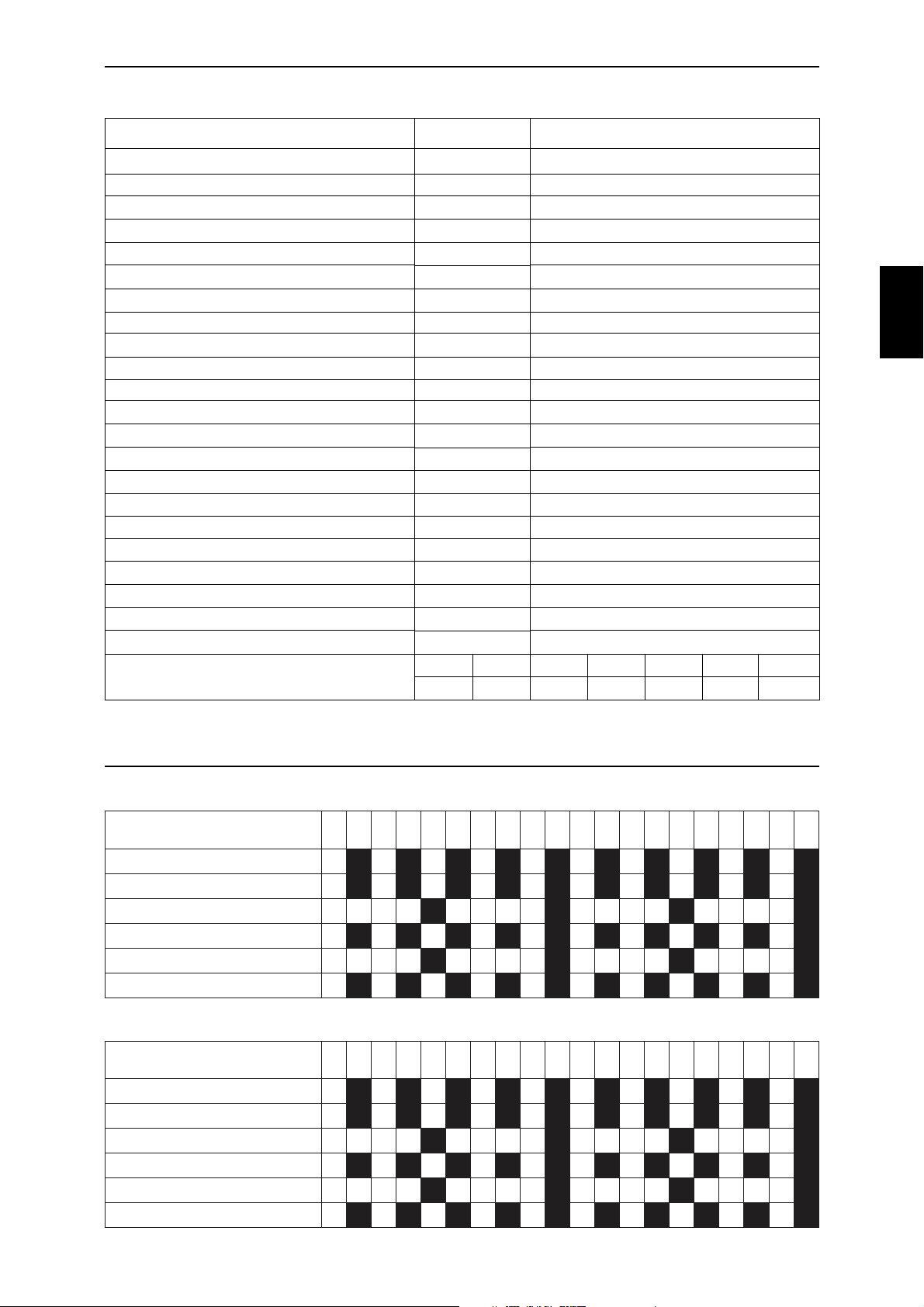
TORQUE VALUES
SUBJECT
Waterpump cover screws
Exhaust pipe screws
Spark plug
Standard torque values M8 M10
TORQUE
5 NmIntake manifold screws
5 NmOil filter cover screws
5 Nm
5 NmValve inspection cover screws
5 Nm
8 NmStator screws
10 NmCrankcase screws
10 Nm
10 NmGearshift lever screw
10 Nm Apply a threadlock liquidKick start lever screw
10 NmValve cover screws
12 NmOil drain plug
12 Nm
12 NmValve adjustment lock nuts
15 NmFront fork triple clamp screws lower (M8)
20 NmFront fork triple clamp screws upper (M8)
25 Nm Apply a threadlock liquidUpper timing sprocket screws
44 NmCylinderstud nuts
50 Nm Left-hand threadFlywheel nut
80 Nm Apply a threadlock liquidIntermediate gear wheel nut
110 Nm
125 NmSwingarm shaft nuts
M4
6 Nm
8 Nm
M5
M6
10 Nm
Apply a threadlock liquidReed valve screws
Apply a threadlock liquidPrimary gear wheel nut
25 Nm 40 Nm
NOTE
M12
40 Nm
3
M16
125 Nm
4
MAINTENANCE SCHEDULE
Chassis - FC, FSc and FX models
SRUOH/TCEJBUSSRUOH/TCEJBUS
SRUOH/TCEJBUSSRUOH/TCEJBUS
SRUOH/TCEJBUS
*liokroftnorF
*diulfekarB
sgnihsub/sgniraebmragniwS
sgnihsubrebrosbakcohS
sgniraebdaehgnireetS
sgniraebleehW
Chassis - FE and FSe models
SRUOH/TCEJBUSSRUOH/TCEJBUS
SRUOH/TCEJBUSSRUOH/TCEJBUS
SRUOH/TCEJBUS
*liokroftnorF
*diulfekarB
sgnihsub/sgniraebmragniwS
sgnihsubrebrosbakcohS
sgniraebdaehgnireetS
sgniraebleehW
55555010101010151515151510202020202525252525203030303035353535353040404040454545454540505050505555555555506060606065656565656070707070757575757570808080808585858585809090909095959595959001001
RRRRR RRRRR RRRRR RRRRR RRRRR RRRRR RRRRR RRRRR RRRRR RRRRR
RRRRR RRRRR RRRRR RRRRR RRRRR RRRRR RRRRR RRRRR RRRRR RRRRR
IIIII IIIII IIIII IIIII
IIIII IIIII IIIII IIIII IIIII IIIII IIIII IIIII IIIII IIIII
IIIII IIIII IIIII IIIII
IIIII IIIII IIIII IIIII IIIII IIIII IIIII IIIII IIIII IIIII
010101010102020202020303030303040404040405050505050606060606070707070708080808080909090909001001
RRRRR RRRRR RRRRR RRRRR RRRRR RRRRR RRRRR RRRRR RRRRR RRRRR
RRRRR RRRRR RRRRR RRRRR RRRRR RRRRR RRRRR RRRRR RRRRR RRRRR
IIIII IIIII IIIII IIIII
IIIII IIIII IIIII IIIII IIIII IIIII IIIII IIIII IIIII IIIII
IIIII IIIII IIIII IIIII
IIIII IIIII IIIII IIIII IIIII IIIII IIIII IIIII IIIII IIIII
001001011011
001
011011021021
011
021021031031
021
031031041041
031
041041051051
041
051051061061
051
061061071071
061
071071081081
071
081081091091
081
091091002002
091
001001
001
002002
002
C: Clean - I: Inspect - R: Replace - *Maximum 12 months interval
9
Page 10
4
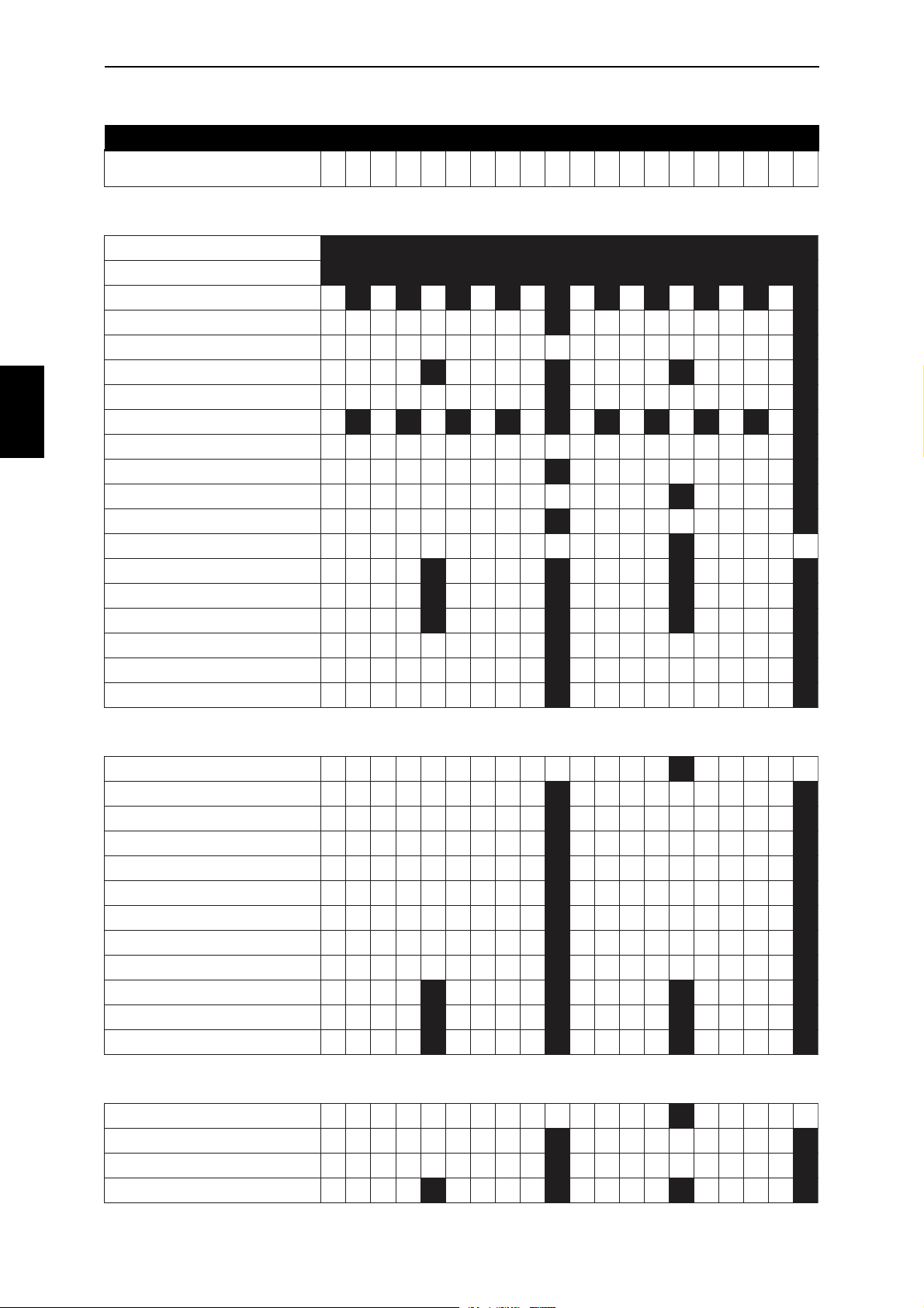
MAINTENANCE SCHEDULE
Engine - FC, FSc and FX models
Please observe: Riding under hard conditions demands more frequent maintenance
4
SRUOH/TCEJBUSSRUOH/TCEJBUS
SRUOH/TCEJBUSSRUOH/TCEJBUS
SRUOH/TCEJBUS
lioenignE
neercsliO
retliforcimliO
evlavdeer.lcnipmupliO
*diuqiltnalooC
)pac.lcni(gulpkrapS
**noitingI/rotanretlA
ecnaraelcevlaV
nip&sgnir.lcninotsiP
gninilrednilyC
dorgnitcennoC
niptfahsknarC
***/**rotterubraC
msinahcemtratskciK
msinahcemtfihsraeG
msinahcemleehweerF:LE
55555010101010151515151510202020202525252525203030303035353535353040404040454545454540505050505555555555506060606065656565656070707070757575757570808080808585858585809090909095959595959001001
RALUGERRALUGER
RALUGERRALUGER
RALUGER
RRRRR RRRRR RRRRR RRRRR RRRRR RRRRR RRRRR RRRRR RRRRR RRRRR RRRRR RRRRR RRRRR RRRRR RRRRR RRRRR RRRRR RRRRR RRRRR RRRRR
CCCCC CCCCC CCCCC CCCCC CCCCC CCCCC CCCCC CCCCC CCCCC CCCCC CCCCC CCCCC CCCCC CCCCC CCCCC CCCCC CCCCC CCCCC CCCCC CCCCC
RRRRR RRRRR RRRRR RRRRR RRRRR RRRRR RRRRR RRRRR RRRRR RRRRR
C/IC/I
C/IC/I C/IC/I
C/I
IIIII RRRRR IIIII RRRRR
IIIII IIIII
IIIII IIIII IIIII IIIII IIIII IIIII IIIII IIIII IIIII IIIII
sgnilaes&sediug.lcnisevlaV
renoisnet.lcniniahcgnimiT
IIIII RRRRR IIIII RRRRR
scsid.lcnimsinahcemhctulC
IIIII IIIII IIIII IIIII
C/IC/I
C/IC/I C/IC/I
C/I
RRRRR RRRRR
RRRRR RRRRR
IIIII IIIII
RRRRR
C/IC/I C/IC/I
C/I
IIIII IIIII
IIIII IIIII
IIIII IIIII
C/IC/I C/IC/I
C/I
001001
001
C/IC/I
C/I
RRRRR
IIIII
C/IC/I
C/I
SGNIRAEBSGNIRAEB
SGNIRAEBSGNIRAEB
SGNIRAEB
dorgnitcennoC
tfahsknarC
tfahsniamxobraeG
tfahsyradnocesxobraeG
murdtfihS
tfahsmaC
etalperusserphctulC
leehwraegtratskciK
leehwraegetaidemretnI
smrarekcoR
.labretnuoctfahsetaidemretnI
recnalabretnuoC
dorgnitcennoC
smrarekcoR
tfahstratskciK
tfahshctulC
RRRRR RRRRR RRRRR RRRRR
RRRRR RRRRR RRRRR RRRRR
RRRRR RRRRR RRRRR RRRRR
SGNIHSUBSGNIHSUB
SGNIHSUBSGNIHSUB
SGNIHSUB
IIIII RRRRR IIIII RRRRR
RRRRR RRRRR
IIIII RRRRR
IIIII RRRRR
IIIII RRRRR
IIIII RRRRR
IIIII RRRRR
IIIII RRRRR
IIIII RRRRR
IIIII IIIII
IIIII IIIII
RRRRR
RRRRR
10
C: Clean - I: Inspect - R: Replace
* Maximum 12 months interval - ** Clean whenever the engine has been washed - *** I(R): Especially needle and needle jet
Page 11
4
MAINTENANCE SCHEDULE
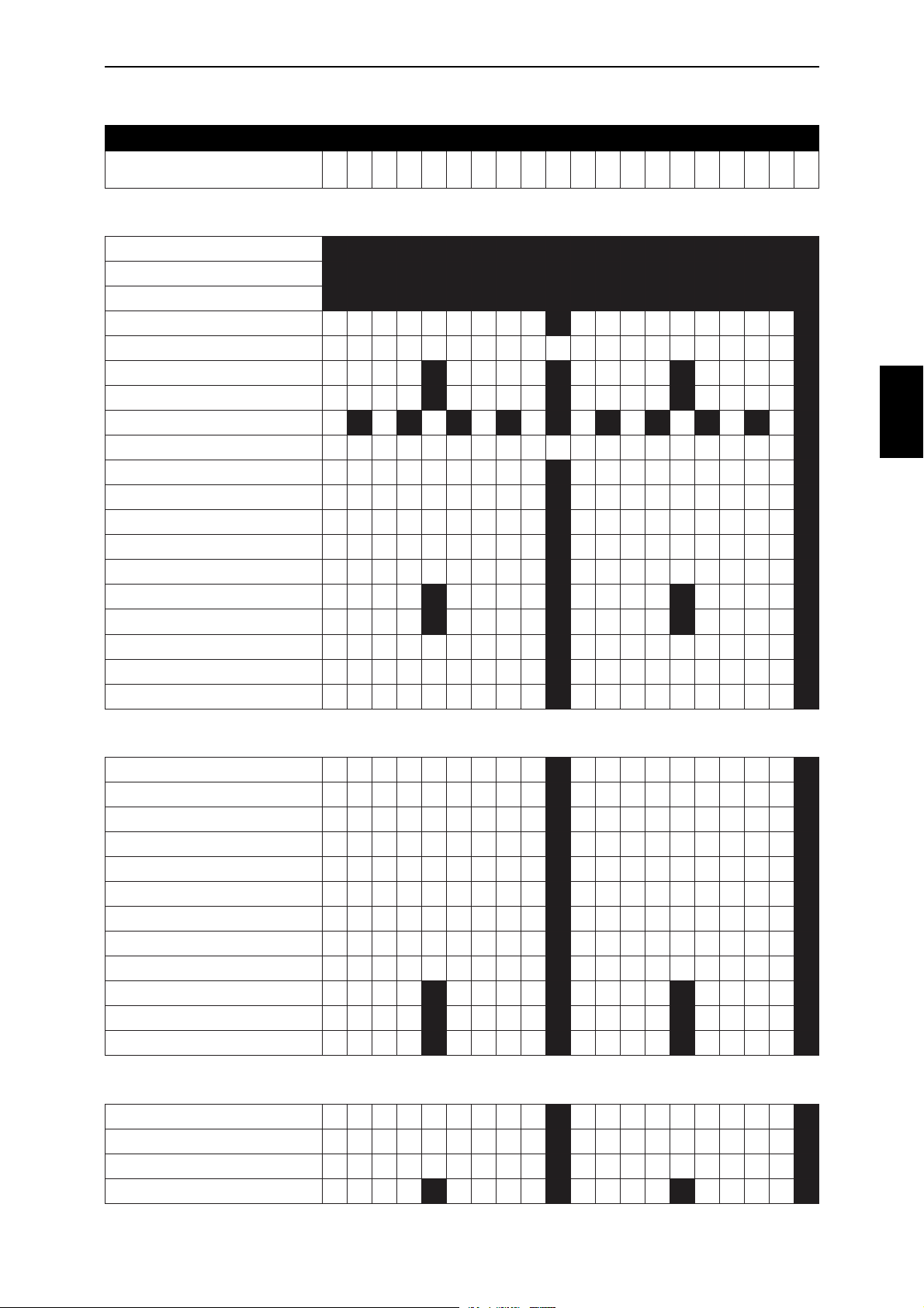
Engine - FE and FSe models
Please observe: Riding under hard conditions demands more frequent maintenance
SRUOH/TCEJBUSSRUOH/TCEJBUS
SRUOH/TCEJBUSSRUOH/TCEJBUS
SRUOH/TCEJBUS
lioenignE
neercsliO
retliforcimliO
evlavdeer.lcnipmupliO
*diuqiltnalooC
)pac.lcni(gulpkrapS
**noitingI/rotanretlA
ecnaraelcevlaV
nip&sgnir.lcninotsiP
gninilrednilyC
dorgnitcennoC
niptfahsknarC
***/**rotterubraC
msinahcemtratskciK
msinahcemtfihsraeG
msinahcemleehweerF:LE
010101010102020202020303030303040404040405050505050606060606070707070708080808080909090909001001
RALUGERRALUGER
RALUGERRALUGER
RALUGER
RRRRR RRRRR RRRRR RRRRR RRRRR RRRRR RRRRR RRRRR RRRRR RRRRR RRRRR RRRRR RRRRR RRRRR RRRRR RRRRR RRRRR RRRRR RRRRR RRRRR
CCCCC CCCCC CCCCC CCCCC CCCCC CCCCC CCCCC CCCCC CCCCC CCCCC CCCCC CCCCC CCCCC CCCCC CCCCC CCCCC CCCCC CCCCC CCCCC CCCCC
RRRRR RRRRR RRRRR RRRRR RRRRR RRRRR RRRRR RRRRR RRRRR RRRRR RRRRR RRRRR RRRRR RRRRR RRRRR RRRRR RRRRR RRRRR RRRRR RRRRR
IIIII RRRRR IIIII RRRRR
IIIII IIIII IIIII IIIII
IIIII IIIII IIIII IIIII IIIII IIIII IIIII IIIII IIIII IIIII
sgnilaes&sediug.lcnisevlaV
renoisnet.lcniniahcgnimiT
scsid.lcnimsinahcemhctulC
IIIII IIIII IIIII IIIII
C/IC/I
C/IC/I C/IC/I
C/I
001001011011
011011021021
021021031031
031031041041
041041051051
051051061061
061061071071
071071081081
081081091091
001
011
021
031
041
051
061
071
C/IC/I
C/IC/I C/IC/I
C/I
RRRRR RRRRR
IIIII RRRRR
IIIII IIIII
RRRRR RRRRR
RRRRR RRRRR
C/IC/I C/IC/I
C/I
IIIII IIIII
IIIII IIIII
IIIII IIIII
C/IC/I C/IC/I
C/I
091091002002
081
091
002002
002
C/IC/I
C/I
RRRRR
4
IIIII
C/IC/I
C/I
SGNIRAEBSGNIRAEB
SGNIRAEBSGNIRAEB
SGNIRAEB
dorgnitcennoC
tfahsknarC
tfahsniamxobraeG
tfahsyradnocesxobraeG
murdtfihS
tfahsmaC
etalperusserphctulC
leehwraegtratskciK
leehwraegetaidemretnI
smrarekcoR
.labretnuoctfahsetaidemretnI
recnalabretnuoC
dorgnitcennoC
smrarekcoR
tfahstratskciK
tfahshctulC
RRRRR RRRRR RRRRR RRRRR
RRRRR RRRRR RRRRR RRRRR
RRRRR RRRRR RRRRR RRRRR
SGNIHSUBSGNIHSUB
SGNIHSUBSGNIHSUB
SGNIHSUB
RRRRR RRRRR RRRRR RRRRR
RRRRR RRRRR
RRRRR RRRRR
IIIII RRRRR
IIIII RRRRR
IIIII RRRRR
IIIII RRRRR
IIIII RRRRR
IIIII RRRRR
IIIII RRRRR
RRRRR RRRRR
IIIII IIIII
IIIII IIIII
C: Clean - I: Inspect - R: Replace
* Maximum 12 months interval - ** Clean whenever the engine has been washed - *** I(R): Especially needle and needle jet
11
Page 12
5
CONTROLS
5
IDENTIFACTION NUMBERS
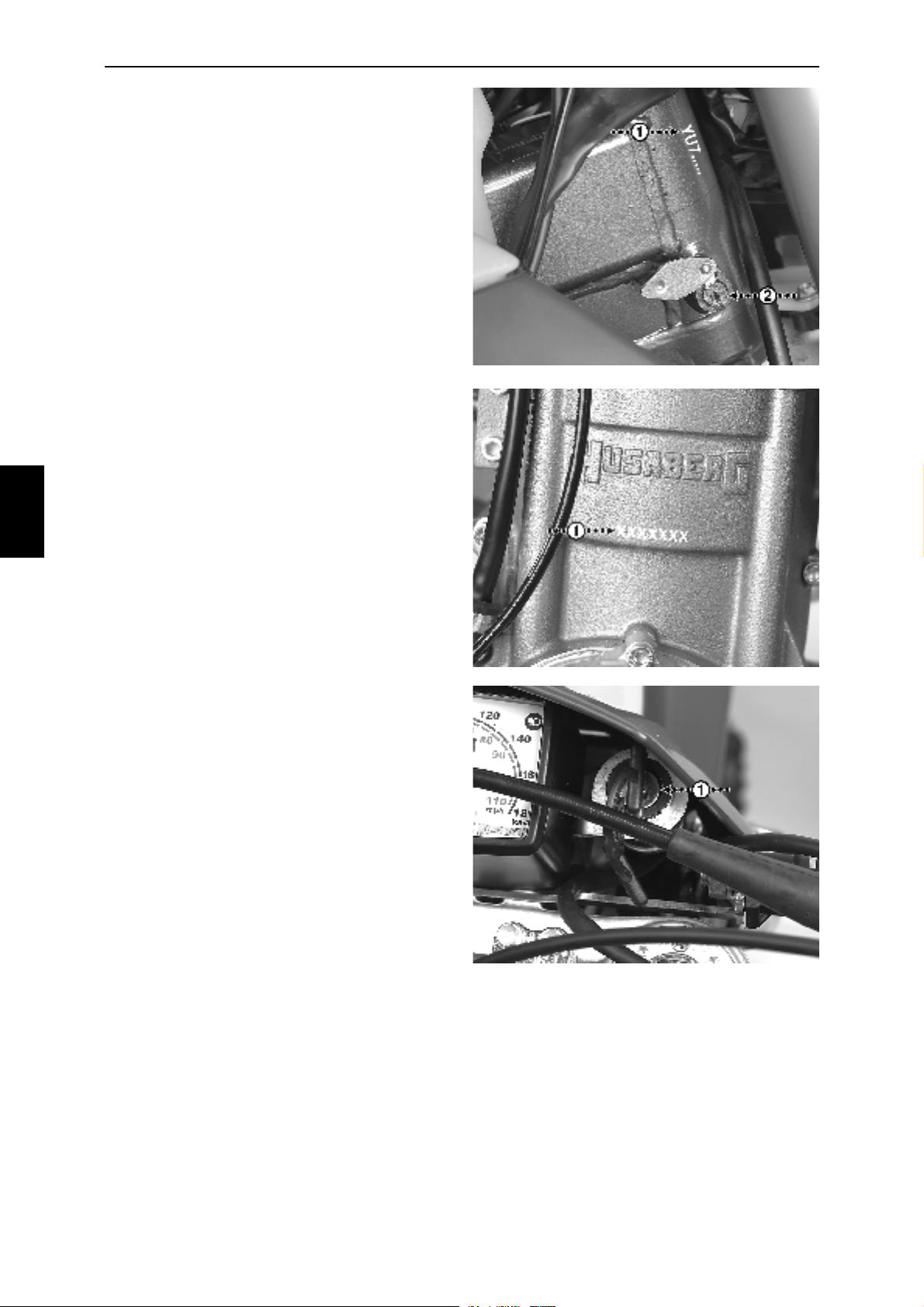
The Vehicle Identification Number is placed on
the right side of the steering head (Fig. 5A-1).
The Engine Number is placed on the right side of
the engine, just below the cylinder (Fig. 5B-1).
STEERING LOCK
The lock (if incl. in equipment) is placed on the
right side of the steering head (Fig. 5A-2).
We recommend you to follow the conditions of
your insurance regarding the use of anti-theft
devices.
Fig.
5A
Fig.
5B
IGNITION LOCK
The ignition lock is either placed to the right of
any speedometer (Fig. 5C-1) or in a separat
bracket.
The first position, maximum counter-clockwise,
means that the engine can not be started. No
lights in function.
The second position, clockwise, means that the
engine can be started with the kick starter but
not with the electrical starter. Available lights in
function.
The third position, clockwise, means that the
engine can be started with both the kick starter
and the electrical starter. Available lights in
function.
Fig.
5C
12
Page 13
5
CONTROLS
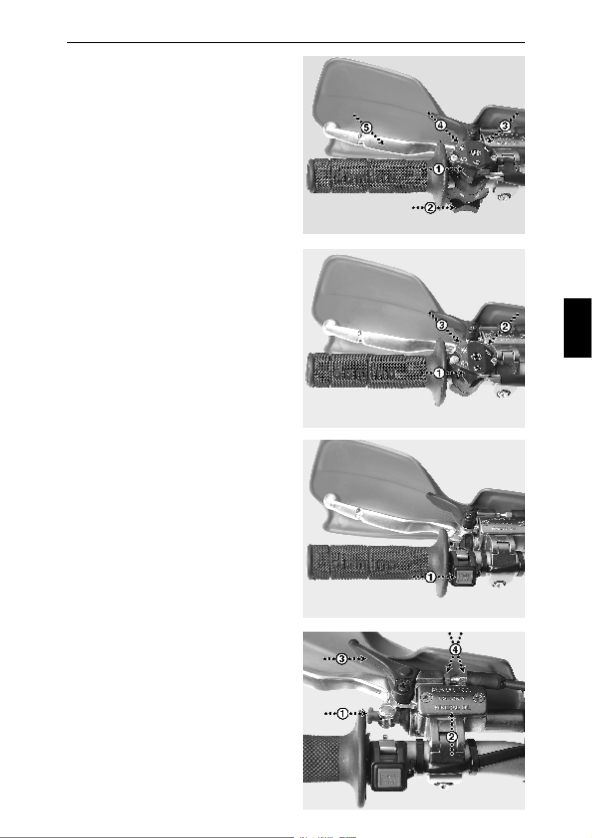
Fig. 5E Combination switch Type I:
1- Headlight switch
(Off - Low - High beam)
2- Turn signal switch
3- Horn button
4- Engine shortcircuit button
5- Clutch lever
Fig. 5F Combination switch Type II:
1- Headlight switch
(Off - Low - High beam)
2- Horn button
3- Engine shortcircuit button
Fig.
5E
Fig.
5F
5
Fig. 5G 1- Engine shortcircuit button
(Motocross models)
Fig. 5H 1- Clutch lever adjustment knob
2- Oil reservoir hydraulic clutch
3- Decompression lever
4- Decompression lever adjustment
Fig.
5G
Fig.
5H
13
Page 14
5
CONTROLS
5
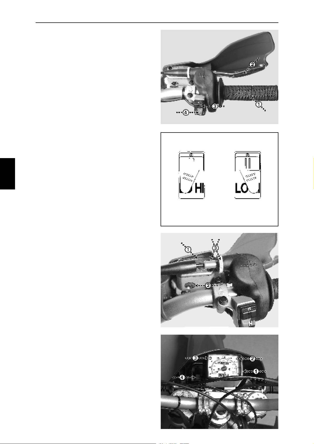
Fig 5I 1- Twistgrip
2- Front brake lever
3- Electrical starter button
(if it is an electrical starter model,
otherwise the button having no
function)
4- Dual ignition curve switch
Fig 5J Low- Normal conditions
High- Starts and heavy conditions
Fig. 7A
Fig.
5I
Fig.
5J
Fig. 5K 1- Reservoir front brake fluid
2- Brake fluid inspection window
3- Throttle wire adjustment
Fig. 5L 1- Speedometer
(If included in equipment)
2- Highbeam indicator lamp
LOW HIGH
Fig.
5K
Fig.
5L
14
3- Turn signal indicator lamp
4- Trip meter knob
Page 15
6
STARTING PROCEDURE
Kick starter models:
Follow the checklist on page 5.
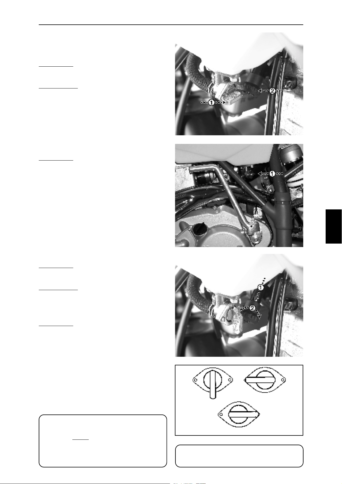
Turn the fuel taps (Fig. 6A-1 & 6B-1) to position
ON (Fig. 6D).
Cold engine: Turn the choke lever (Fig 6A-2) to
position ON (Fig. 6C-1) by pulling it downwards
and twisting it 90° (Fig. 6C-2).
Warm engine: Choke lever should be in OFF
position.
Put the gearshift lever into neutral.
With the throttle fully closed, make a distinct and
long kick all the way through the operational orbit
of the kick start lever. If the engine does not start,
let the kick start lever return all the way back in
order to provide the maximum distance for the
kick start lever and also activating the additional
semi-automatic decompression system.
Cold engine: Warm the engine up (the throttle a
little bit opened) with the choke on until it runs
smoothly.
Engine idling, pull the clutch lever fully towards
the handlebar and engage the 1st gear by
pushing the gearshift lever downwards. Open the
throttle slightly at the same time as you slowly
and gently release the clutch lever.
Shift the gears as soon as adequate rpms have
been achieved.
Fig.
6A
Fig.
6B
6
Electrical starter models:
Follow the checklist on page 5.
Turn the fuel taps (Fig. 6A-1) to position ON (Fig.
6B-1).
Cold engine: Turn the choke lever (Fig 6A-2) to
position ON (Fig. 6B-2) by pulling it downwards
and twisting it 90°.
Warm engine: Choke lever should be in OFF
position.
Put the gearshift lever into neutral.
With the throttle fully closed, push the electrical
start button.
Cold engine: Warm the engine up (the throttle a
little bit opened) with the choke on until it runs
smoothly.
Engine idling, pull the clutch lever fully towards
the handlebar and engage the 1st gear by
pushing the gearshift lever downwards.
Open the throttle slightly at the same time as
you slowly and gently release the clutch lever.
Shift the gears as soon as adequate rpms have
been achieved.
The electrical start models are all equipped with
kick starters. Follow the instructions above: ”Kick
starter models”, if used.
Fig.
6C
Fig.
6D
ON OFF
ATTENTION:
In order to ensure an easy start the
following must be correctly adjusted:
The valve clearances, the idling speed,
the spark plug gap and the mixture
screw of the carburettor.
RESERVE
ATTENTION:
Do not drain all of the battery capacity
15
Page 16
7 A
ENGINE
LUBRICATION SYSTEM:
Always use a synthetic oil of a well-known brand,
viscosity SAE 5W-50.
Depending on the basic design of the engine;
competition purposes = equal to a small sized
engine thus giving a small capacity of oil, it is vital
that the oil is frequently changed.
Packed into the crate of a totally new motorcycle
is an additional microfilter. The filter installed in
the engine and the engine oil have to be changed
after the first two hours of operation. The oil screen
has to be fully cleaned at the same time.
After the first change of oil and filter, including
cleaning of the oil screen, the intervals are
maximum 5 hours (Motocross, Super Motard
Competition and Cross Country models) or 10
hours (all other models) regarding change of oil
and cleaning of the screen and every 25/50 hours
regarding exchange of the microfilter.
Fig.
7A
Fig.
7B
7
After every 100 hours the reed valve of the
lubication system has to be inspected and
cleaned.
Oil and filter change and cleaning of oil screen:
The oil is preferably changed while the engine is
warm.
ATTENTION:
Take care - the oil could be very hot
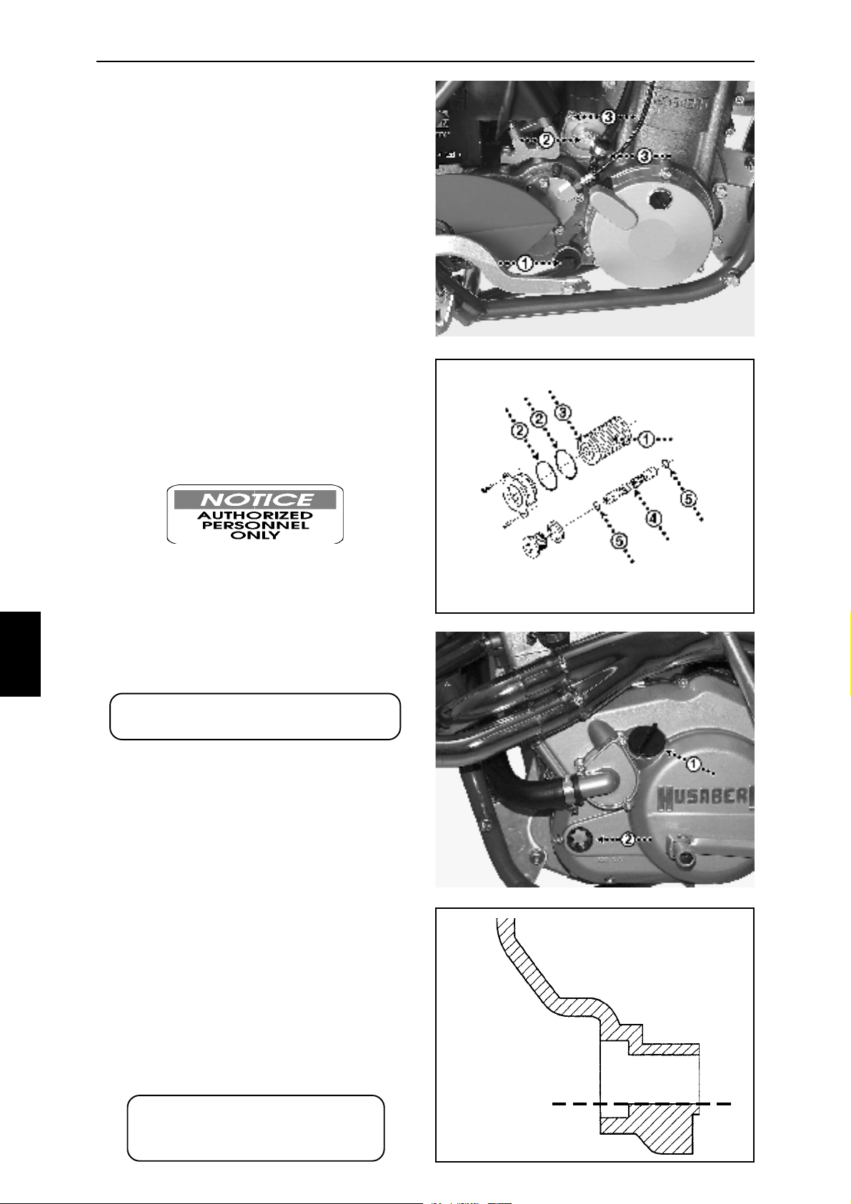
Drain the oil by removing the oil drain plug (Fig.
7A-1, wrench No. 13) and the attached oil screen.
Remove the cover of the microfilter by removing
the ignition cable clamp (Fig. 7A-2, wrench No. 8)
and the two allen screws (Fig. 7A-3, allen key No.
4) and pull out the cover and filter by using one M
6 screw as a puller into the center of the cover.
Lubricate the surface of the cover's O-rings and
the O-ring of the new microfilter (Fig. 7B-2, 7B-3).
Insert the microfilter in reverse order of
disassembly.
Refit the oil drain plug and the attached, well
cleaned, oil screen.
Refill the engine with the adequate amount of oil;
1,0 litre, through the filler hole (Fig. 7C-1). Correct
level of oil as shown (Fig. 7C-2 & 7D)
Whenever checking the oil level the motorcycle/
engine has to be in an upright position.
Fig.
7C
Fig.
7D
16
ATTENTION:
Service more frequently when
riding under hard conditions
OIL LEVEL
Page 17
7 B
ENGINE
IGNITION:
The ignition system is a CDI-system without any
contact-breaker to change or any other moving
parts apart from the flywheel. However, the system
has to be frequently checked and cleaned for a
maximum of durability and performance.
The inside of the ignition cover, the stator, the
flywheel and the surroundings are preferably
cleaned after every time the motorcycle has been
used and/or washed (cover removal; three allen
screws, allen key No.5). Due to the heat of the
engine a condensation is built up around the stator
and flywheel which could cause the system to
work improperly. Check the surface of the cover
for any damages in order to avoid any leakages.
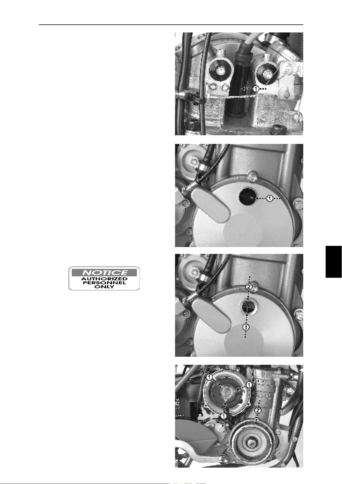
Frequently check the spark plug (Fig. 7E-1) for
wear and the colour of the electrode coating (spark
plug wrench, article No. 270007-01). The colour
ought to be pale brown. A dark or black colour
means that the carburettor's setting is on the rich
side and a light or white colour means that it is
too lean (see "FUEL & COOLING CARBURETTOR”).
Fig.
7E
Fig.
7F
Check also the spark plug electrode gap. The
correct electrode gap is 0,6 mm.
Recommended spark plug is NGK DCPR8E.
Tightening torque 12 Nm.
Ignition timing:
Remove the inspection cover (Fig. 7F-1).
Put the engine in TDC position (see ”ENGINE VALVE ADJUSTMENT”).
The ignition is propely set if the right mark on the
flywheel (Fig. 7G/H-2) is aligned with the mark on
the stator (Fig. 7G-1).
If the ignition needs to be adjusted, remove the
cover, slightly undo the three screws of the stator
(Fig. 7H-1) and adjust the stator.
Tighten the screws.
Fig.
7G
Fig.
7H
7
17
Page 18
7 C
ENGINE
AIRFILTER:
To avoid any engine damages or lack of power
the air filter has to be frequently cleaned or
replaced.
Always use a well-known brand of filter oil after
cleaning. Use an airfilter cleaning solvent of a
well-known brand.
Always check the surface of the filter attachment
and the filter basket for any damages.
Always check the surfaces behind the filter for
any loose particles and carefully clean the
surfaces.
Airfilter removal:
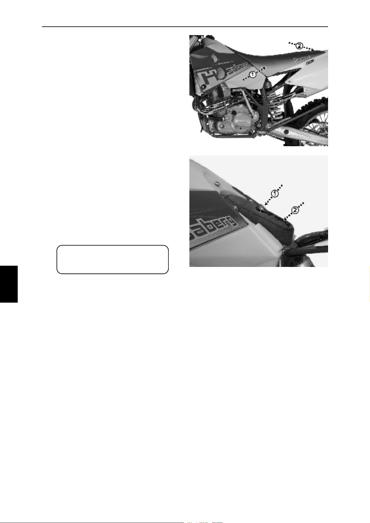
Remove the seat (Fig. 7I-1, one quick release
screw on top of the seat).
Remove the wing nut (Fig. 7J-1) holding the
airfilter and airfilter basket (Fig. 7J-2).
Pull the airfilter basket out of the airfilter.
Wash the filter carefully.
Soak the filter in filter oil and squeeze it slightly
for any superfluous oil.
Put the airfilter basket into the filter.
Assembly in reverse order of disassembly.
Fig.
7I
Fig.
7J
7
ATTENTION:
Service more frequently when
riding under hard conditions
18
Page 19
7 D
ENGINE
VALVES:
The clearances between the valve adjustment
screws and the valve stems have to be checked
after 2 hours of operation if the engine is brand
new or any parts of the valves, valve seats or
rockerarms have been changed.
The interval between the checks of the clearences
is after that every 10 hours (Motocross, Super
Motard Competition and Cross Country models)
or 20 hours (all other models).
Valve adjustment:
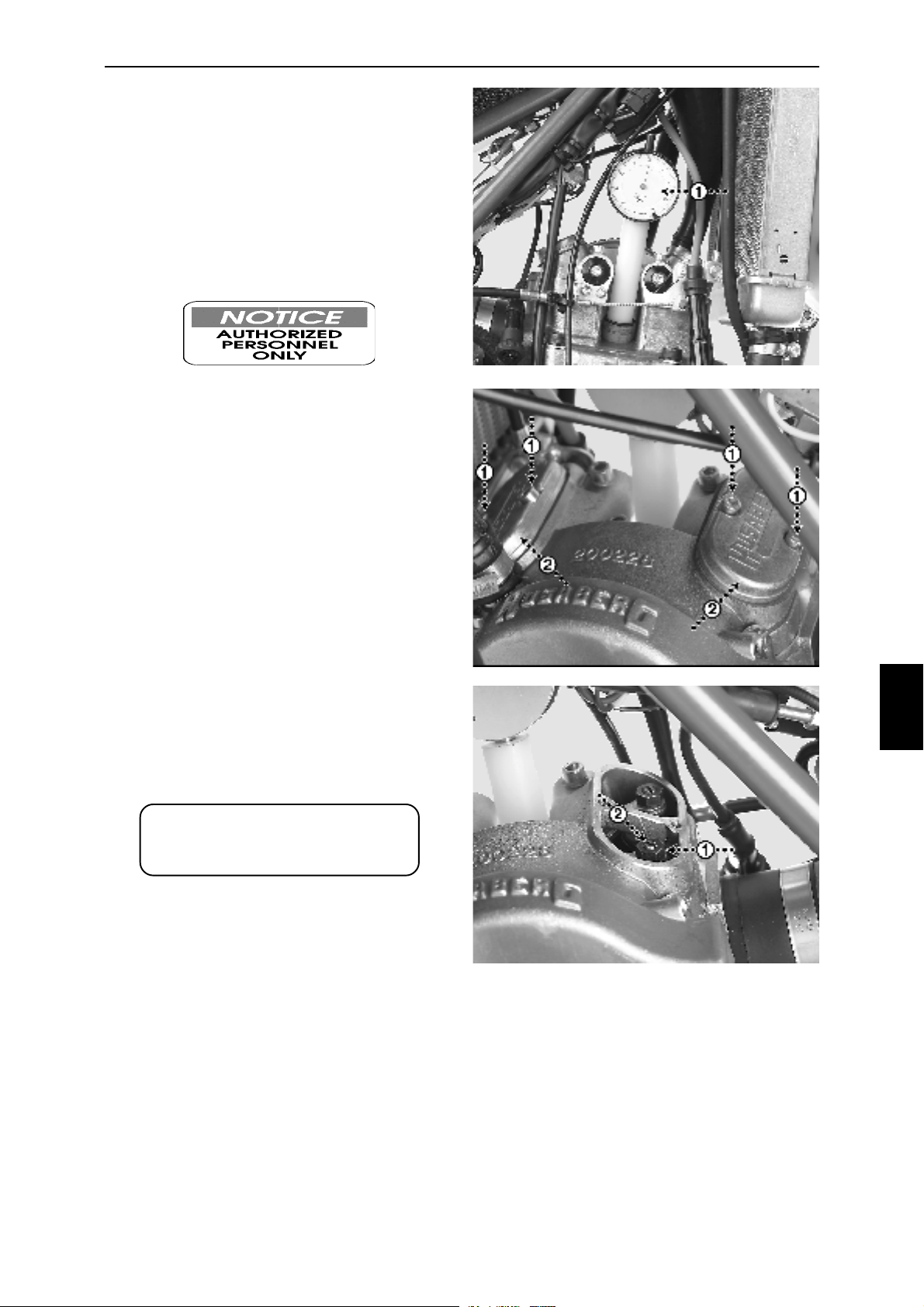
Remove the fuel tank (see "FUEL & COOLING
- FUEL").
Put the engine in TDC position on compression
stroke: Remove the ignition cover, install a dial
indicator into the spark plug hole (Fig. 7K-1) and
turn the flywheel (wrench No. 17), clockwise, in
order to find the upper position of the piston.
Fig.
7K
Fig.
7L
Remove the two valve inspection covers (Fig.
7L-1, 2, allen key No. 4) including the gaskets.
Check the clearances of the valves; 0.10 mm on
both the intake valves as well as the exhaust
valves. Adjust if necessary by releasing the lock
nut (Fig. 7M-1, wrench No. 10) and then by
adjusting the screw (Fig. 7M-2) into the adequate
clearance.
Refit in the reverse order of disassembly.
Replace the gaskets of the inspection covers if
necessary.
ATTENTION:
Service more frequently when
riding under hard conditions
Fig.
7M
7
19
Page 20
8 A
FUEL & COOLING
CARBURETTOR:
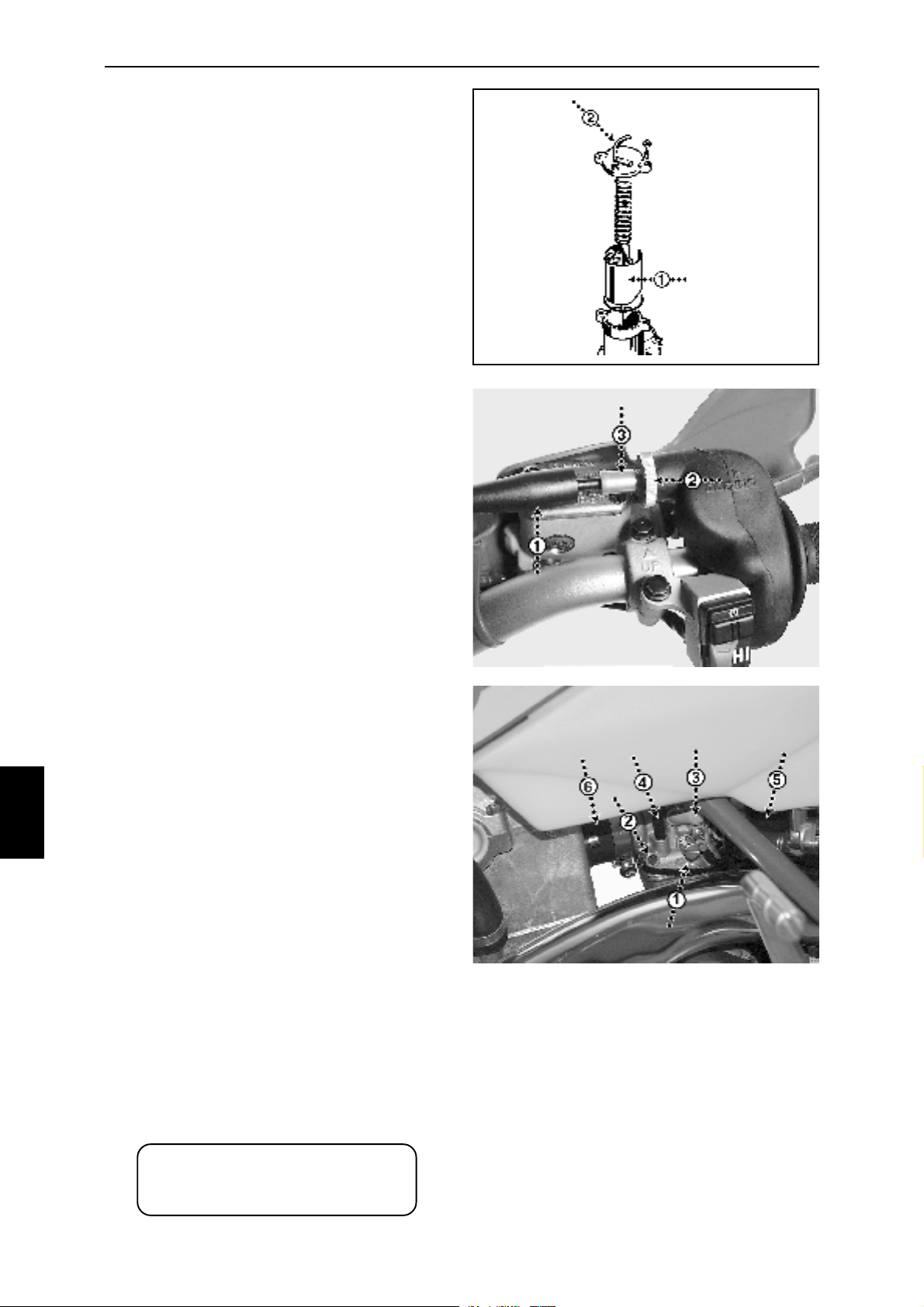
Always make sure that the throttle (Fig. 8A-1)
returns to a fully closed position.
Always make sure that the twistgrip and cable
move easily.
Always keep the twistgrip and cable well cleaned
and lubricated. The tube on top of the carburettor
(Fig. 8A-2) is a point of deterioration to the cable
and thus a vital part of the cable to be inspected.
Always make sure of a 1-2 mm clearance in the
twistgrip. Adjustment is done by removing the
dust protection (Fig. 8B-1), releasing the lock nut
(Fig. 8B-2) and adjusting the adjustment screw
(Fig. 8B-3).
Always check the intake manifold (Fig. 8C-6) and
the airfilter tube (Fig. 8C-5) for any cracks and/
or leakages and replace if necessary.
Always keep the shaft of the choke lever (Fig.
8C-3) well lubricated.
Always check that the overflow tubes (Fig. 8C-4)
on each side of the carburettor are positioned in
a vertical position straight from the outlets and
not crossed nor hanging over the carburettor.
Always ensure that an appropriate fuel is used
(minimum 98 octane) in order to get the most
out of the motorcycle and to ensure a proper
function of the engine.
Fig.
8A
Fig.
8B
8
Carburettor setting:
To ensure an easy start of the engine, a high
level of performance and a reduction of any risk
of engine damages, the carburettor has to be
correctly set and adjusted.
The carburettor has an idling screw (Fig. 8C-1)
and a mixture screw (Fig. 8C-2) that have to be
properly adjusted. In order to carry out a proper
adjustment of these, the engine has to be warm.
With the twistgrip fully closed, turn the idling
screw to a position that makes the engine run
smoothly at idling speed (approximately 16001800 rpm).
Adjust the mixture screw to a position of a
maximum idling speed.
If the engine now runs in a too high idling speed
unscrew the idling screw until a satisfying idling
speed is established.
A guideline regarding the mixture screw is 1½2½ turns from the bottom position of the screw.
Depending on the altitude and the humidity, the
adjustment may have to be changed whenever
riding under various conditions.
Fig.
8C
20
ATTENTION:
Service more frequently when
riding under hard conditions
Page 21
8 B/C
FUEL & COOLING
FUEL:
The Husaberg motorcycle is developed and
designed for competition use and this makes a
high compression ratio a necessity.
In order to avoid any damages caused by too
low grade of octane we highly recommend you
to use a fuel of minimum 98 octane.
Fuel tank:
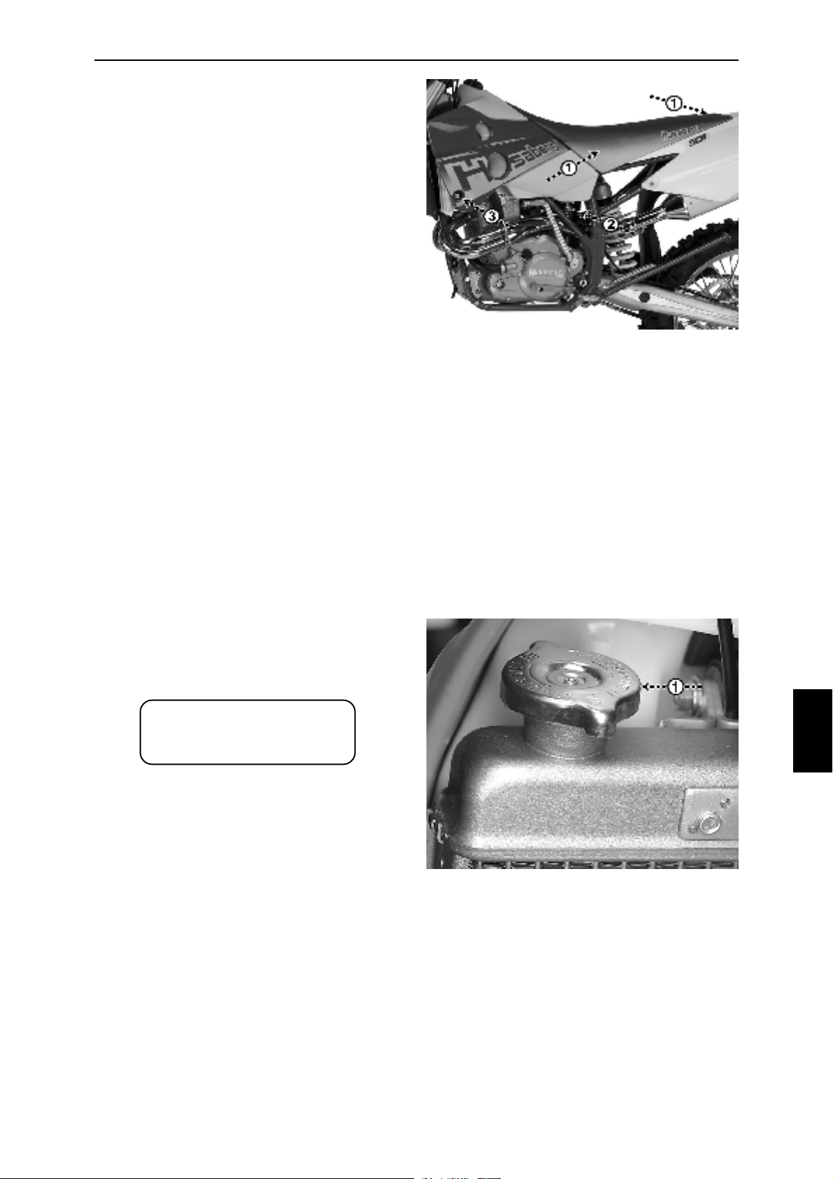
Remove the seat (Fig. 8D-1, see ”ENGINE AIRFILTER”).
Remove the the two clamps holding the upper
fuel lines attached to each fuel tap (Fig. 8D-2).
Remove the two hexagon bolts holding the left
and right radiator spoiler attached to the radiator
(Fig. 8D-3, wrench No.8).
Remove the fuel tank by lifting it up in the rear
end and moving it up and backwards.
Fig.
8D
RADIATOR:
Always make sure that the coolant level is correct
by checking that the coolant is visible after
removal of the radiator filler cap (Fig. 8E-1).
WARNING:
Do not check the coolant
level while the engine is hot.
A mixture of 50% water and 50 % anti-freeze
with a corrosion inhibitor is recommended.
Check all connections and hoses for any
leakages. Check the radiator cells for any
leakages.
Fig.
8E
8
21
Page 22
9
CLUTCH & DECOMPRESSION
CLUTCH:
Check the hydraulic line for any leakages or
deterioration.
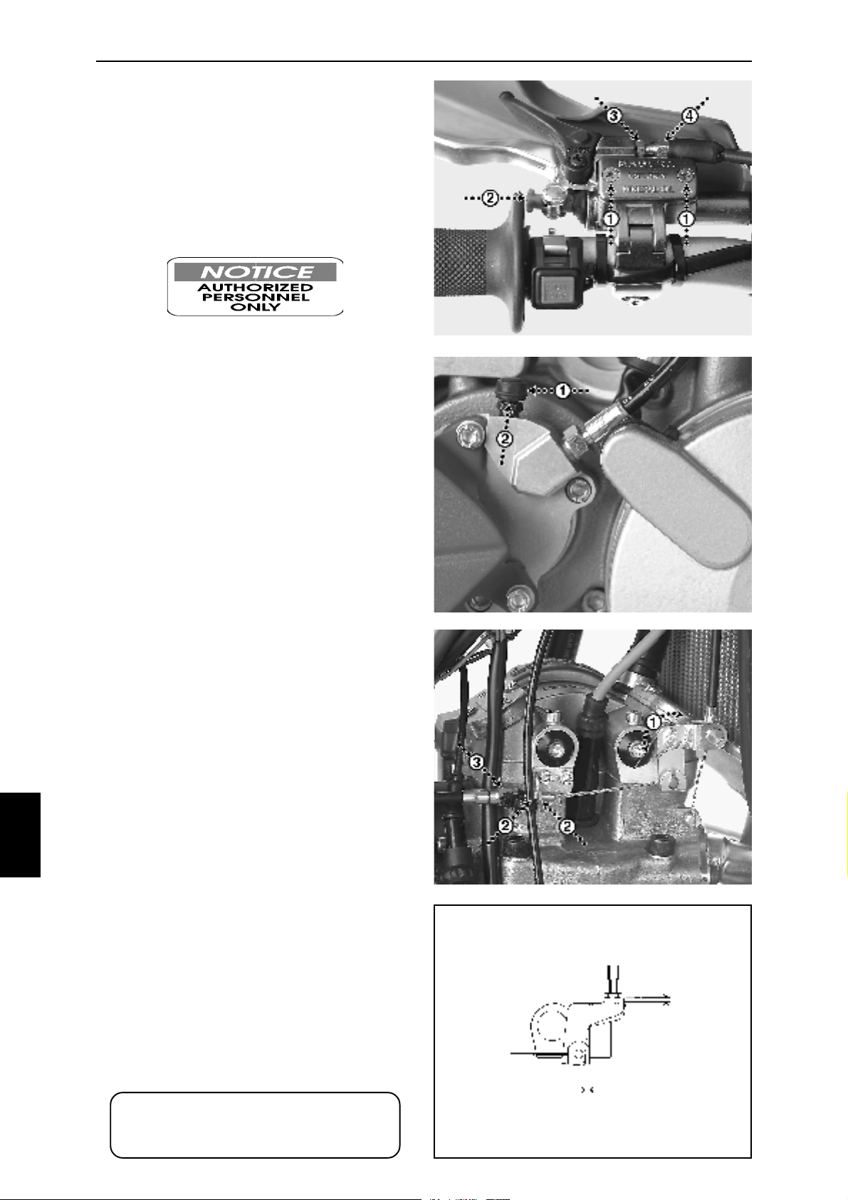
Always check the level of fluid in the reservoir. The
cover of the reservoir has to be removed in order
to check the level (Fig. 9A-1).
Adjust the pressure point of the lever according to
your own preferences with the adjustment knob
(Fig. 9A-2). Always keep a clearance in between
the lever and the point of pressure.
If the package of discs measures less than 19,6mm
the discs are to be replaced.
Air bleeding of clutch:
Undo the screws of the cover (Fig. 9A-1) just slightly
in order for the oil to flow over. Set the adjustment
knob (Fig. 9A-2) in its outer position and keep the
lever fully open during the whole operation. Put a
rag or likewise around the oil reservoir.
Open the air nipple (Fig. 9B-2) 1-1½ turn. Slip or
screw a suitable syringe (article no. 270032-01),
fully filled with mineral oil, onto the nipple and inject
the oil into the system. Make sure that no air gets
through the syringe into the system. Inject the whole
contents of the syringe in one operation.
Remove the syringe and close the air nipple
immediately.Tighten the screws of the cover and
adjust the point of pressure to your liking.
Fig.
9A
Fig.
9B
9
DECOMPRESSION SYSTEM:
Although all models are equipped with a fully
automatic decompression system, activated by the
camshaft, they are also equipped with a system
activated by the kick start plus a manually operated
one with a lever on the handlebar.
Always make sure that the clearance of the lever is
as shown.
Always keep the cable well lubricated and make
sure that it moves easily.
Adjustment of decompression cables:
Put the engine in TDC (see ”ENGINE - VALVE
ADJUSTMENT”).
Make sure that the manual decompression cable
has an adequat clearance before performing the
adjustment of the semi-automatic adjustment.
Adjustment is done by releasing the two lock nuts
(Fig. 9C-2, wrench No. 10) before turning the
adjustment screw (Fig. 9C-3, wrench No. 10).
The adjustment of the manual lever is done by
releasing the lock nut (Fig. 9A-3) before turning
the adjustment screw (Fig. 9A-4).
Fig.
9C
Fig.
9D
2 mm
±1 mm
22
ATTENTION:
Less clearances than the required
cause severe engine damages
Page 23
10 A
WHEELS & BRAKES
FRONT WHEEL:
Always check the front wheel for any damages
regarding the rim, the spokes and the nipples.
Check the bearings for any wear and/or damages.
Tighten any loose spokes (spoke wrench No.5.5).
All spokes have to be equally tensioned.
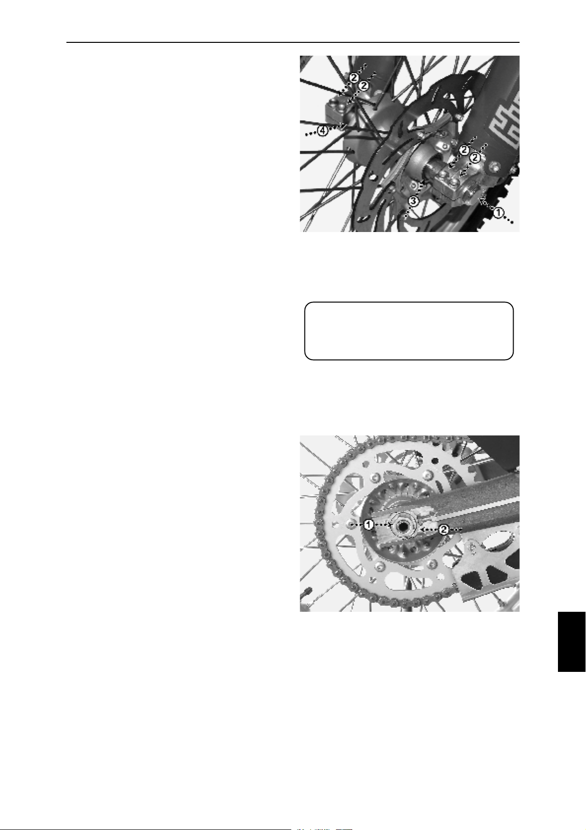
Removal of front wheel:
Remove the hexagon nut (Fig. 10A-1, wrench No
27).
Remove the four hexagon bolts (Fig. 10A-2, wrench
No.10), two on each side of the front fork legs.
Remove the front wheel axle, incl. the left hand
spacer (Fig. 10A-3) and the right hand spacer or
speedometer gear lever (Fig. 10A-4) and remove
the front wheel.
Check the wear of the brake pads at the same
time.
Assembly of front wheel:
Put the front wheel in by first sliding the brake disc
into the brake caliper (in between the two pads).
Put the cleaned and lubricated wheel axle in, from
right to left, with the spacer (Fig. 10A-3) on the left
side of the hub and the thicker part of the spacer
towards the front fork. The rest in reverse order of
disassembly.
Tighten the bolts. Max. torque of the four M8 bolts
(Fig. 10A-2) 15 Nm.
Fig.
10A
ATTENTION:
Always put the motorcycle on a
stable centerstand whenever
removing either front or rear wheel.
REAR WHEEL:
Always check the rear wheel for any damages
regarding the rim, the spokes and the nipples.
Check the bearings for any wear and/or damages.
Retighten any loose spokes (spoke wrench No.6).
All spokes have to be equally tensioned.
Removal of rear wheel:
Remove the nut (Fig. 10B-1, wrench No.27) and
the chain tensioner sledge (Fig. 10B-2) on the right
side of the swingarm.
Remove the wheel axle and push the wheel
forward.
Slip the chain off the wheel sprocket and remove
the rear wheel.
Check the wear of the brake pads at the same
time.
Assembly of rear wheel:
Put the rear wheel in by first sliding the brake disc
into the caliper (in between the two pads).
Slip the chain onto the sprocket and put the cleaned
and lubricated wheel axle in, from left to right,
including the left and right chain tensioner sledges.
Adjust the chain tensioner (see ”WHEELS &
BRAKES - CHAIN DRIVING") if necessary.
Tighten the rear wheel shaft nut.
Fig.
10B
10
23
Page 24
10 A
WHEELS & BRAKES
WHEEL BEARING RENEWAL:
Remove the wheel (see previous page).
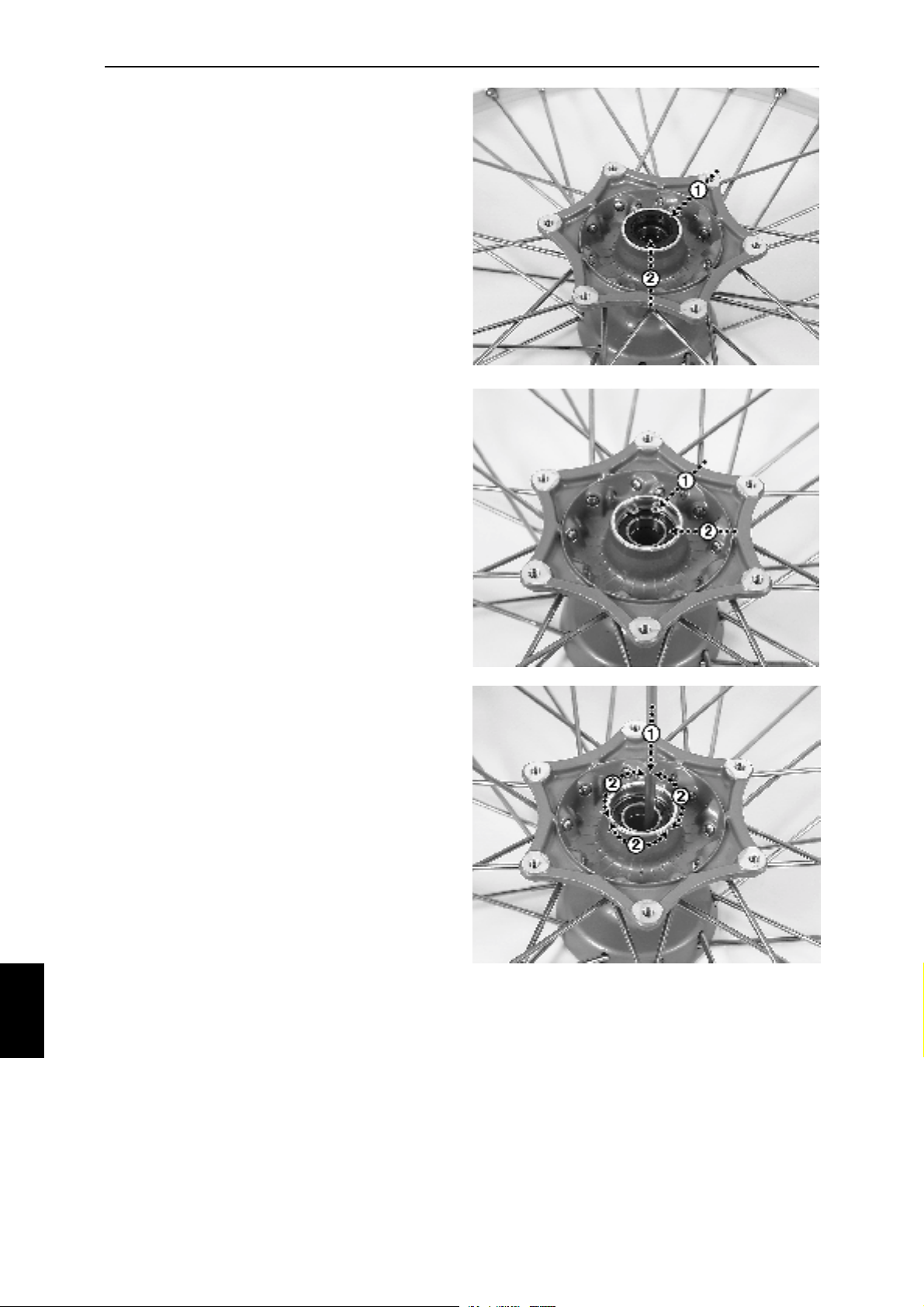
Position the wheel so that the bearings (Fig.
10D-2) are easily removed from the inside of
the hub.
Remove the radial sealing (Fig. 10C-1) in order
to be able to remove the circlip (Fig. 10D-1),
one circlip only but two sealings per each hub.
Push the spacing sleeve to one side (Fig. 10C-
2) in order to position a suitable triblet onto the
backside of the inner ring of the opposite
bearing.
By crosswise (Fig. 10E-2) tapping onto the
bearing (Fig. 10E-1), knock the bearing out of
the hub. Follow the same procedure regarding
the opposite bearing. Be careful not to damage
the bearing bases in the hub.
Measure the length of the spacer sleeve which
should be minimum:
front wheel with speedometer
63,3 ± 0,15 mm
front wheel without speedometer
80,3 ± 0,15 mm
Fig.
10C
Fig.
10D
10
rear wheel
121,6 ± 0,15 mm
Replace if necessary.
Install the new bearing on the circlip side into
the hub and put on the circlip.
Turn the wheel and install the spacer sleeve
towards the bearing on the circlip side and then
install the next bearing towards the spacer
sleeve. The spacer sleeve should just slightly
be touching the two bearings.
Make sure to position the bearings in alignment
with the bearing bases in the hub and the spacer
sleeve in alignment with the two bearings.
Install the sealings and assembly the wheel in
the reverse order of disassembly.
Fig.
10E
24
Page 25
10 B
WHEELS & BRAKES
CHAIN:
The Husaberg motorcycle is delivered with a
chain of X-ring type. If properly serviced it will
last for a long period.
Always keep the chain well cleaned and
lubricated and make sure that the chain is
properly tensioned.
Always make sure that the chain is not showing
any signs of wear that may cause it to break or
causing damages to the front- and/or rear
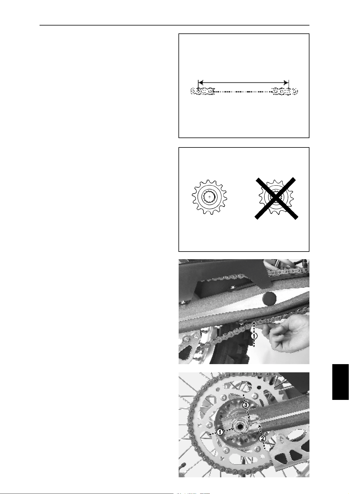
sprocket. With the chain tensioned, the
maximum wear as shown (Fig. 10F).
Chain lubrication:
Remove the rear wheel (see "WHEELS &
BRAKES - WHEELS").
Remove the swingarm (see "SUSPENSION SWINGARM”).
After cleaning of the removed chain; use a
suitable solvent, wipe it off with a clean and dry
cloth.
Lubricate the chain by using a well-known brand
of O-ring lubrication.
Assembly in reverse order of disassembly.
Fig.
10F
Maximum 272 mm
123 161718
Fig.
10G
Sprockets:
Always check the front- and rear sprocket for
any wear that may cause damages to the chain
(Fig. 10G).
Whereafter changing to a new O-ring chain,
always follow the recommendations of the
supplier regarding maintenance and wear limits.
Chain tension control:
Control of the tension is done when the bike is
in an upright, unloaded, position (wheels on the
ground and no centerstand used).
Press the chain upwards, using just a minor
force. When properly tensioned you should be
able to just barely touch the swingarm protection
at the position as shown (Fig. 10H-1) with the
chain.
Chain tension adjustment:
Undo the rear wheel axle by slacking off the
nut (Fig. 10I-1, wrench No.27 ).
Release the two lock nuts of the chain
tensioners on each side of the swingarm (Fig.
10I-2, wrench No.13).
Adjust the chain with the chain tensioner bolts
(Fig. 10I-3, wrench No.13) to a correct tension
on both sides. Measure the distances in
between the swingarm shaft and the rear wheel
shaft on each side of the motorcycle and make
sure that the distances are exactly the same.
Tighten the lock nuts of the chain tensioners.
Tighten the rear wheel axle.
CORRECT INCORRECT
Fig.
10H
Fig.
10I
25
10
Page 26
10 C
WHEELS & BRAKES
FRONT BRAKE:
The Husaberg motorcycle is equipped with a
Brembo hydraulic disc brake. For your own safety
it needs to be frequently serviced and checked.
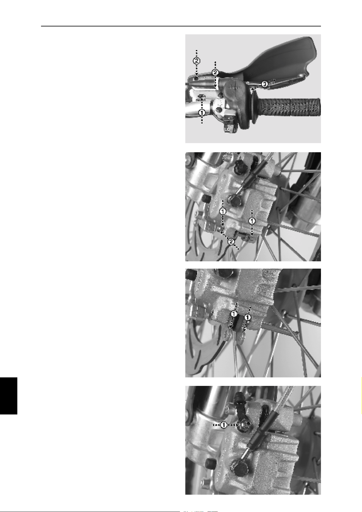
Always check the level of brake fluid in the
reservoir. The reservoir has a transparent
"window" with a mark for the lowest level (Fig.
10J-1).
Always check the brake hose for any leakage and/
or deterioration.
Always check the wear of the brake pads. Change
the pads if the thickness of each brake pad,
excluding the metal part, is less than 1,5 mm.
Brake fluid:
Add fluid; DOT 4, by removing the two screws
(Fig. 10J-2, Philips screwdriver) and removing the
cover and the membrane. Take care - the fluid is
toxic and could also harm the surfaces of the
motorcycle.
Brake pads:
Remove the two clips (Fig. 10K-1) holding the
brake pad pin (Fig. 10K-2).
Remove the two brake pads by removing the pin
and pulling the two pads out (Fig. 10L-1).
Fit new pads in reverse order.
Fig.
10J
Fig.
10K
10
Air bleeding:
Ensure that the air nipple (Fig. 10M-1, wrench
No.11) is easily opened.
With the nipple in closed position; pull the lever
towards the handlebar a couple of times and keep
it under pressure towards the handlebar the last
time.
Open the air nipple slightly and the brake lever,
still under pressure, will move towards the
handlebar allowing any occuring air, and fluid, to
run through the brakeline and nipple.
With the brake lever fully towards the handlebar
close the air nipple and then release the lever.
Repeat the above mentioned steps until no more
air is visible from the air nipple. Make sure that
the reservoir has enough fluid all the time (not
below the MIN level).
Adjustment of brake lever:
The front brake lever has an adjustment knob (Fig.
10J-3) that allows a personal adjustment of the
pressure point. Always keep a clearance in
between the lever and the point of pressure.
Fig.
10L
Fig.
10M
Tightening torque brake caliper/bracket (M8):
25 Nm / Use a threadlock liquid on the bolts.
26
Page 27
WHEELS & BRAKES
FRONT BRAKE: Supermotard.
The supermotard models are equipped with
Beringer hydraulic front brakes. Fluid level and
safety check are carried out in the same
manor as on the enduro brake. The brake
disc however, is of a coated cast iron type,
which demands a run in period. To obtain the
best result of braking power and durability,
the following recommendations should be
followed.
1. Disc and pads must be run in for 100300 km, depending on your riding,
using progressively applied power.
Do not overheat the disc. Avoid
violent, repeated or continuous
braking. A smooth surface on the
disc will indicate that the running in
period is complete.
2. Be careful. The first braking must be
very light. They are reserved to
remove the coating from the braking
track. In case of not respecting this,
a risk exists of damaging pads and
disc (vibration) not covered by the
guarantee. During the running in period,
braking power will be reduced
temporarily.
3. Inspect the brake disc regularly. It must
be brilliant or blue or dark brown. If the
brake area turns dull, as if sandpapered,
rapid wear of disc and pads may occur.
This can happen after many low power
brakings, or if you ride in rain for a long
time. In this case it is advisable to do
some powerful brakings in order to
laminate the pads friction surface and
put down a new protective deposit on
the disc.
4. For cleaning the caliper and hub of disc,
you must never use aggressive
chemicals, solvent or “brake cleaner”
Avoid high-pressure cleaner.
5. Wear:
· Min thickness of disc. 4.5 mm.
(Replace disc)
· Max rotation play between hub
and disc. 2 mm. ( Replace
hub)
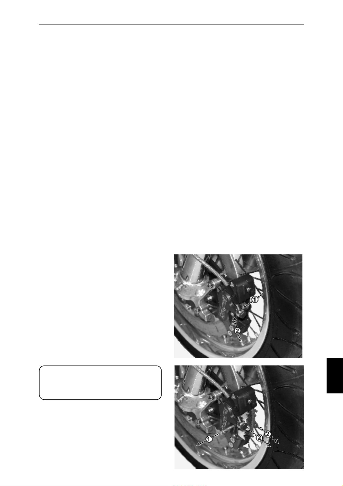
Brake pads:
Remove the clip (Fig. 10N-1) holding the brake
pad pin (Fig. 10N-2).
Remove the two brake pads by removing the pin
(Fig. 10O-1) and pulling the two pads out (Fig.
10O-2).
Fit new pads in reverse order.
Do not forget that a new pair of brake pads will
require a slight run in period.
ATTENTION:
Always put the motorcycle on a
stable centerstand whenever
removing either front or rear wheel.
Fig.
10N
Fig.
10O
10
27
Page 28
10 C
WHEELS & BRAKES
REAR BRAKE:
The Husaberg motorcycle is equipped with a
Brembo hydraulic disc brake. For your own safety
it needs to be frequently serviced and checked.
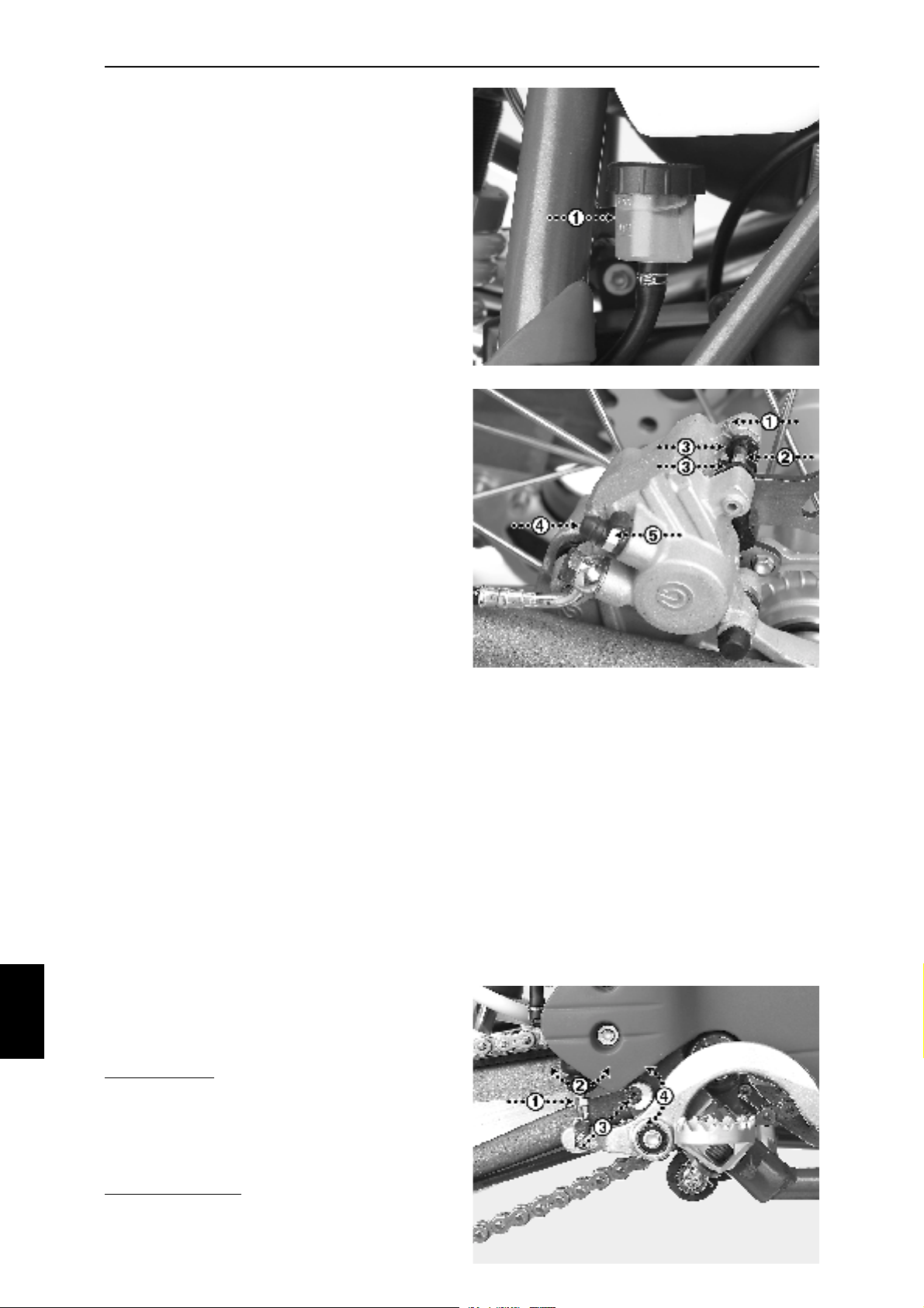
Always check the level of brake fluid in the
reservoir (Fig. 10P-1). The level has to be within
the MIN and MAX marks when the motorcycle is
upright.
Always check the brake hoses for any leakage
and/or deterioration.
Always check the wear of the brake pads. Change
the pads if the total thickness of each pad is less
than 1,5 mm, excluding the metal part.
Brake fluid:
Add fluid; DOT 4, by removing the cap on the
reservoir and the gasket. Take care - the fluid is
toxic and could also harm the surfaces of the
motorcycle.
Brake pads:
Remove the clip (Fig. 10Q-1) holding the brake
pad pin (Fig. 10Q-2).
Remove the two brake pads by removing the pin
and pulling the two pads out (Fig. 10Q-3).
Fit new pads in reverse order.
Fig.
10P
Fig.
10Q
10
Air bleeding:
Remove the dust cap (Fig. 10Q-4) and ensure
that the air nipple (Fig. 10Q-5, wrench No.11) is
easily opened. With the nipple in closed position;
push the lever downwards a couple of times and
keep it under pressure the last time. Open the
nipple slightly and the brake lever, still under
pressure, will move downwards allowing any air,
and fluid, to run through the brakeline and nipple.
Before releasing the pressure onto the lever; close
the air nipple.
Repeat the steps until no more air is visible. Make
sure that the reservoir has enough fluid all the
time.
Adjustment of brake lever:
The rear brake lever is easily adjusted into a
personal point of pressure and height of the lever.
Fig.
10R
Pressure point: release the lock nut (Fig. 10R-1,
wrench No.10) of the pushrod and turn the
pushrod into selected position (Fig. 10R-2).
Always keep a clearance in between the lever and
the point of pressure. Tighten the locknut.
Height of the lever: release the allen screw (Fig.
10R-3, allen key No. 4) and turn the eccentric
adjustment (Fig. 10R-4) into selected position.
Tighten the allen screw.
28
Page 29
11 A
SUSPENSION
FRONT SUSPENSION:
The Husaberg motorcycle is delivered with an
adjustable front fork from WP. For a maximum
performance it needs to be adjusted according
to the riding conditions and the rider's weight
and preferences. The front fork is pre-adjusted
from the factory as follows:
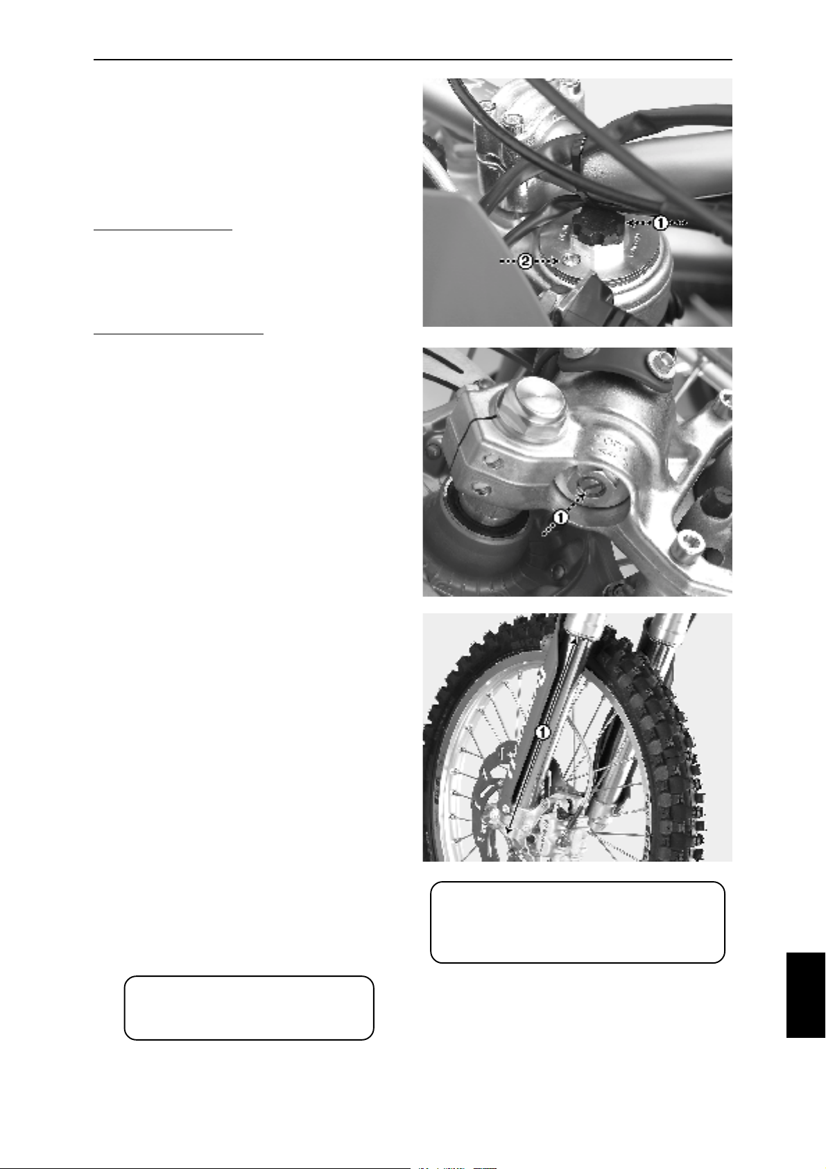
Rebound damping:
Adjustment knob (Fig. 11A-1) in 12th position
(FE models) or 16th position (FC, FX and FS
models) from the bottom position on both front
fork legs.
Compression damping:
Adjustment screw (Fig. 11B-1) in 20th position
(on all models) from the bottom position on both
front fork legs.
+ = more damping / - = less damping
Air bleeding of front fork:
The front fork ought to be bleeded after every
time the motorcycle has been used.
The front fork unloaded; undo the air bleed
screws (Fig. 11A-2) on both front fork legs until
you hear the air pass.
Tighten the screws.
Fig.
11A
Fig.
11B
Static spring deflection/oil change:
Put the motorcycle on a centerstand in order to
get the front wheel off the ground. Measure the
distance (Fig. 11C-1).
Put the motorcycle on the ground (both wheels
on the ground and unloaded).
Grab the handlebar and push the front fork
firmly down a couple of times.
Measure the distance once again which now
ought to be 20-35 mm less than the first time.
If the distance is outside these 20-35 mm the
pre-load of the front fork has to be adjusted. The
pre-load ought to be in between 5-20 mm.
Oil change:
The oil needs to be changed after every 20 hours,
FE and FSe models, and 10 hours, FC, FSc
and FX models, for a maximum performance
and durability.
Follow the instructions of the WP Service Manual.
ATTENTION:
Service more frequently when
riding under hard conditions
Fig.
11C
ATTENTION:
Always put the motorcycle on a
stable centerstand whenever
removing either front or rear wheel.
11
29
Page 30
11 A
SUSPENSION
REAR SUSPENSION: Off road.
The Husaberg motorcycle is delivered with an
adjustable shock absorber from WP. For a
maximum performance it needs to be adjusted
according to the riding conditions and the rider's
weight and preferences. The shock absorber
is pre-adjusted from the factory as follows:
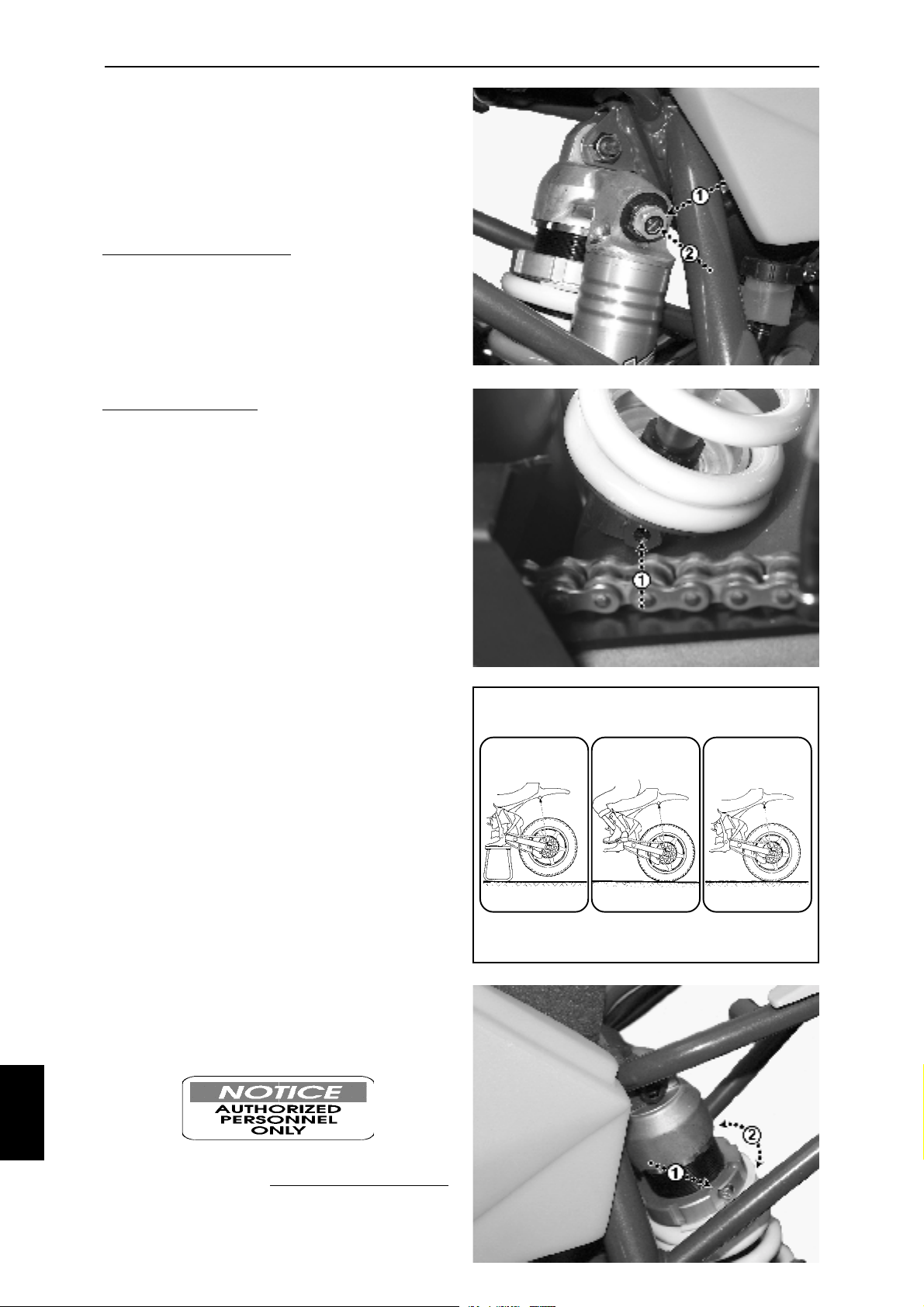
Compression damping:
Adjustment knob low speed (Fig. 11D-2) in the
15th position from the inner, most clockwise,
position.
Adjustment knob high speed (Fig. 11D-1) two
full revolutions (+- 0.5) from the inner, most
clockwise, position.
Rebound damping:
Adjustment screw (Fig. 11E-1) in 25th position
from the bottom, most clockwise position.
+ = more damping / - = less damping
Static spring deflection:
Put the motorcycle on a stand in order to get
the rear wheel off the ground and the shock
absorber fully unloaded. Measure the distance
A1 (Fig. 11F).
Put the motorcycle on the ground; both wheels
on the ground and the rider, incl. apparel,
helmets etc., sitting on the seat and the feet on
the footrests.
Measure the distance A2 (Fig. 11F) which now
ought to be 85-100 mm less than distance A1.
If the distance is outside these limits, adjust the
pre-load ring (Fig. 11G-2) by slacking off the lock
screw (Fig. 11G-1, allen key No. 6) and then
turning the ring.
Tighten the lock screw after an appropriate
preload has been achieved.
With the motorcycle still on the ground, but now
totally unloaded, measure the distance A3 (Fig.
11F) which now ought to be 30-35 mm less than
A1.
If the distance A3 is less than 30 mm - the spring
is too soft. Try to adjust the rings until mean
distances have been achieved according to A2
and A3*.
If the distance is more than 35 mm - the spring
is too stiff. Try to adjust the rings as above*.
A1
Fig.
11D
Fig.
11E
Fig.
11F
A2 A3
Fig.
11G
11
*If not possible - Let
change to an appropriate spring.
30
Authorized Personnel
Page 31
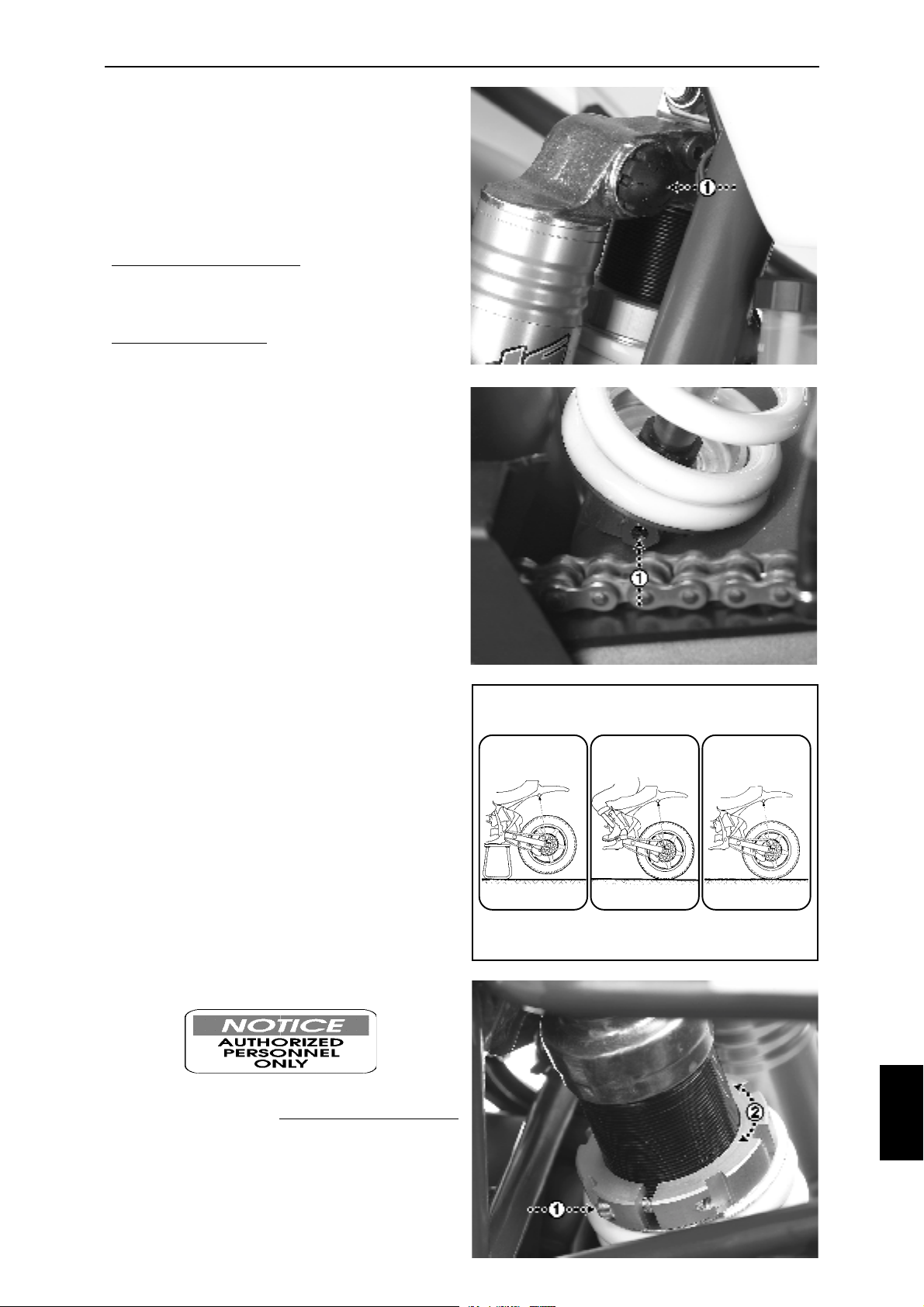
SUSPENSION
REAR SUSPENSION: Supermotard.
The Husaberg motorcycle is delivered with an
adjustable shock absorber from WP. For a
maximum performance it needs to be adjusted
according to the riding conditions and the rider's
weight and preferences. The shock absorber
is pre-adjusted from the factory as follows:
Compression damping:
Adjustment knob (Fig. 11H-1) in the 6th position
from the outer, most counterclockwise, position.
Rebound damping:
Adjustment screw (Fig. 11I-1) in 16th position
from the bottom, most clockwise position.
+ = more damping / - = less damping
Static spring deflection:
Put the motorcycle on a stand in order to get
the rear wheel off the ground and the shock
absorber fully unloaded. Measure the distance
A1 (Fig. 11J).
Put the motorcycle on the ground; both wheels
on the ground and the rider, incl. apparel,
helmets etc., sitting on the seat and the feet on
the footrests.
Measure the distance A2 (Fig. 11J) which now
ought to be 85-100 mm less than distance A1.
If the distance is outside these limits, adjust the
pre-load ring (Fig. 11K-2) by slacking off the lock
screw (Fig. 11K-1, allen key No. 6) and then
turning the ring.
Tighten the lock screw after an appropriate
preload has been achieved.
With the motorcycle still on the ground, but now
totally unloaded, measure the distance A3 (Fig.
11J) which now ought to be 10-25 mm less than
A1.
If the distance A3 is less than 10 mm - the spring
is too soft. Try to adjust the rings until mean
distances have been achieved according to A2
and A3*.
If the distance is more than 25 mm - the spring
is too stiff. Try to adjust the rings as above*.
A1
Fig.
11H
Fig.
11I
Fig.
11J
A2 A3
*If not possible - Let
Authorized Personnel
change to an appropriate spring.
Fig.
11K
11
31
Page 32
11 B/C
SUSPENSION
STEERING HEAD:
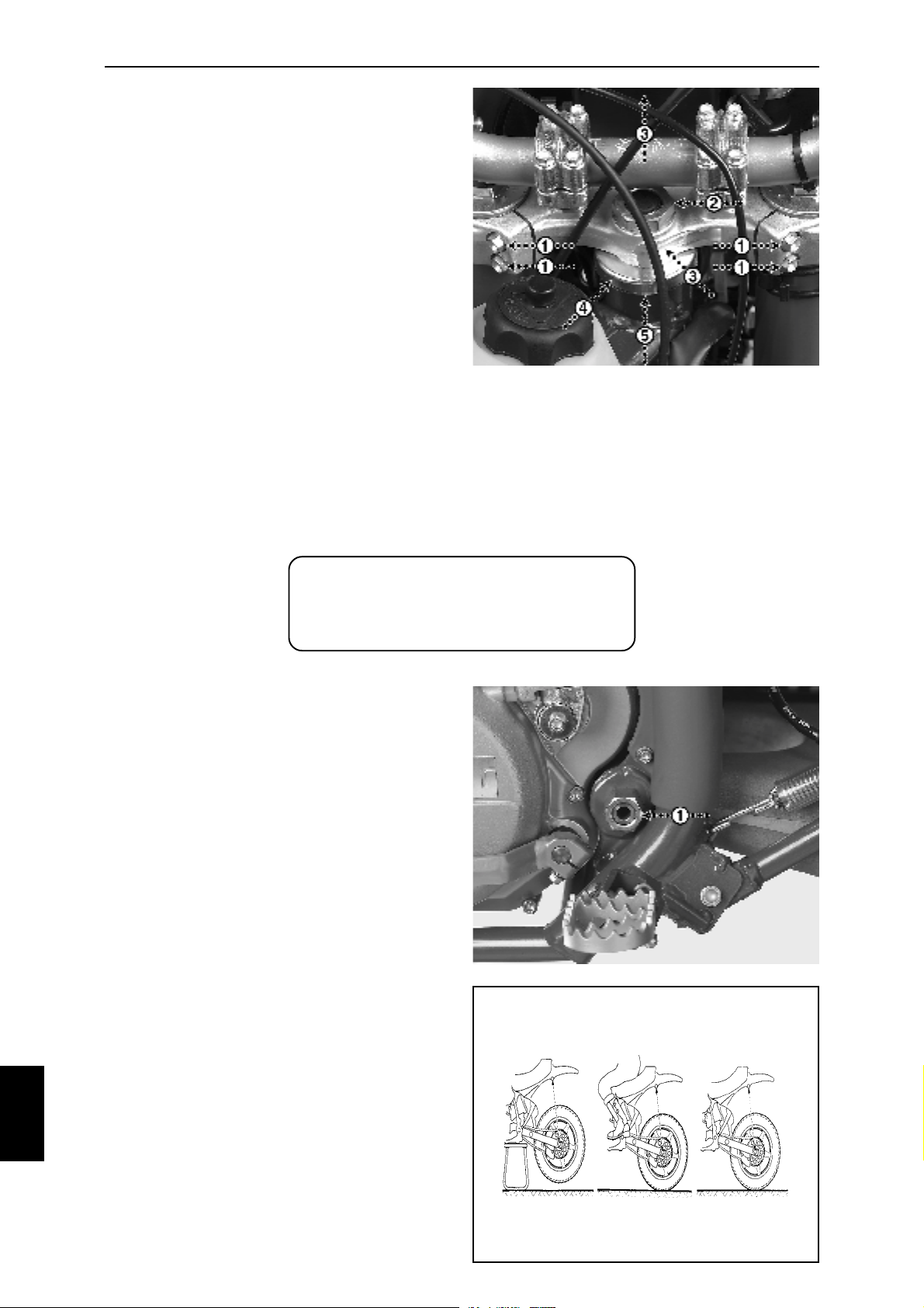
The clearance has to be checked frequently.
Put the motorcycle on a centerstand with the
front wheel fully off the ground.
Turn the handlebar in both directions. It should
not be either too easy nor too hard to move.
Also move it front and backwards in order to
check the clearance (no "clicking" sound).
To adjust, undo the four hexagon screws of the
upper tripleclamp (Fig. 11L-1, wrench No.10),
undo the lock nut on top of the upper tripleclamp
(Fig. 11L-2, wrench No. 32) and lift off the
complete tripleclamp including handlebar etc.
Remove the dust protection (Fig. 11L-4) turn
the adjustment nut underneath (Fig. 11L-5) until
appropriate clearance is obtained. The easiest
way to feel this is by turning the adjustment nut
until you feel a slight resistance while moving
the steering from left to right and then turning
the adjustment nut ¼ of a turn back (counterclockwise).
Assembly in reverse order.
Fig.
11L
11
ATTENTION:
Do not use a highpressure jet-cleaning
equipment on surfaces around
bearings and other fragile components.
SWINGARM:
The bearings and the bushings of the swingarm
have to be frequently checked and serviced. It
should be dissasembled after every 50 hours
in order to be checked, cleaned and lubricated.
Removal and lubrication:
Put the motorcycle on a center stand.
Remove the seat (see "ENGINE - AIR FILTER”).
Remove the rear wheel (see "WHEELS &
BRAKES - WHEELS").
Remove the upper bolt of the shock absorber
(wrench No.17 and allen key No. 8) and lean
the shock absorber backwards.
Remove the lower bolt of the shock absorber
(wrench No. 17 and allen key No. 8) and remove
the shock absorber.
Remove the swingarm shaft nut and shaft (Fig.
11M-1, wrench No. 21) and release the
swingarm from the frame.
Check the bearings (4 pcs) and the bushings
(2 pcs) in the swingarm for any damages or
wear. Replace if necessary.
Clean every part thoroughly and apply a grease
of a well-known brand onto the bearings,
bushings and other surfaces that need to be
lubricated.
Refit everything in reverse order.
Tighten all screws, bolts and nuts.
Fig.
11M
Fig.
11N
32
Page 33
12
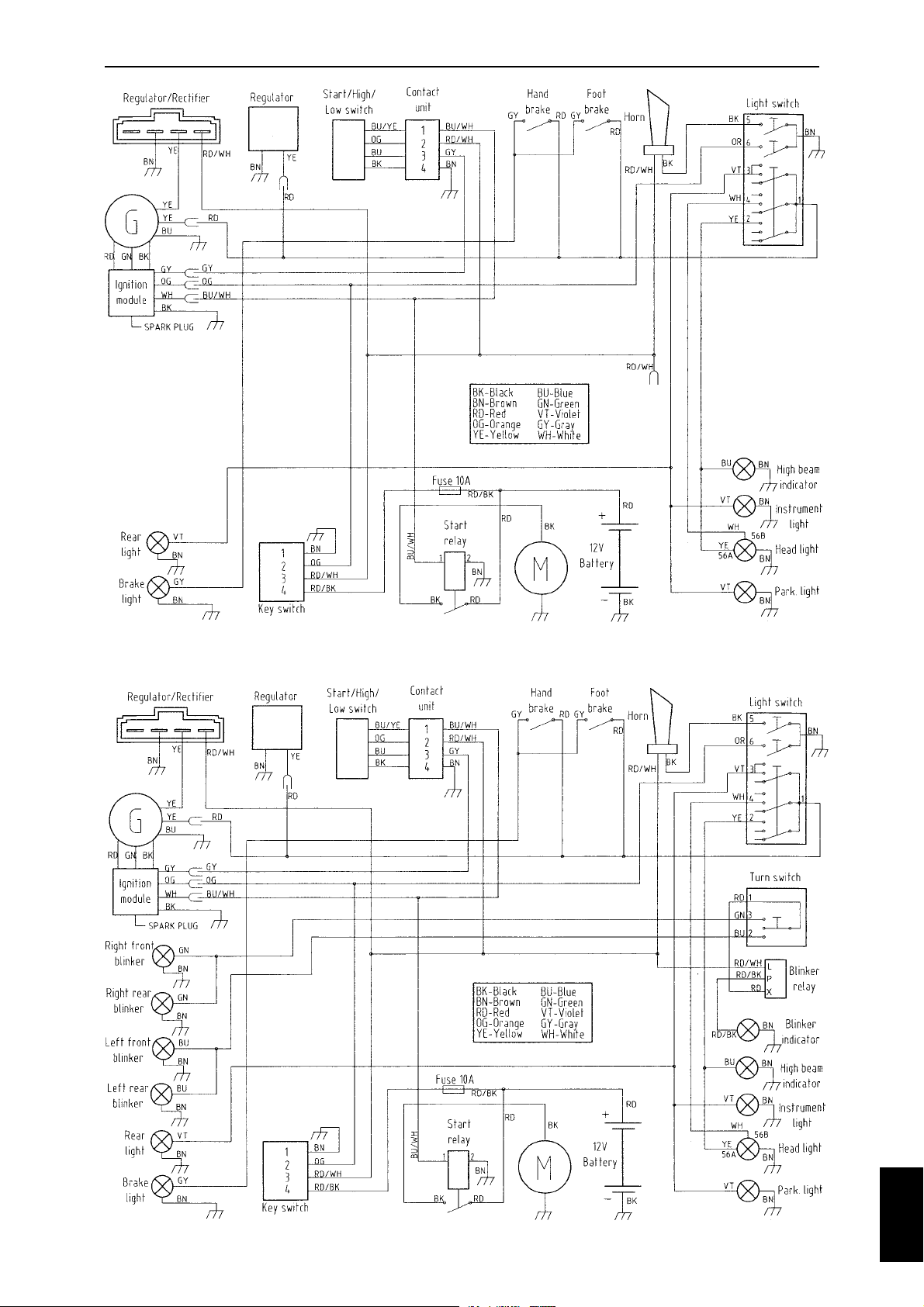
WIRING DIAGRAMS
FE and FS electrical starter models without turn signals
FE and FS electrical starter models with turn signals
12
33
Page 34
12
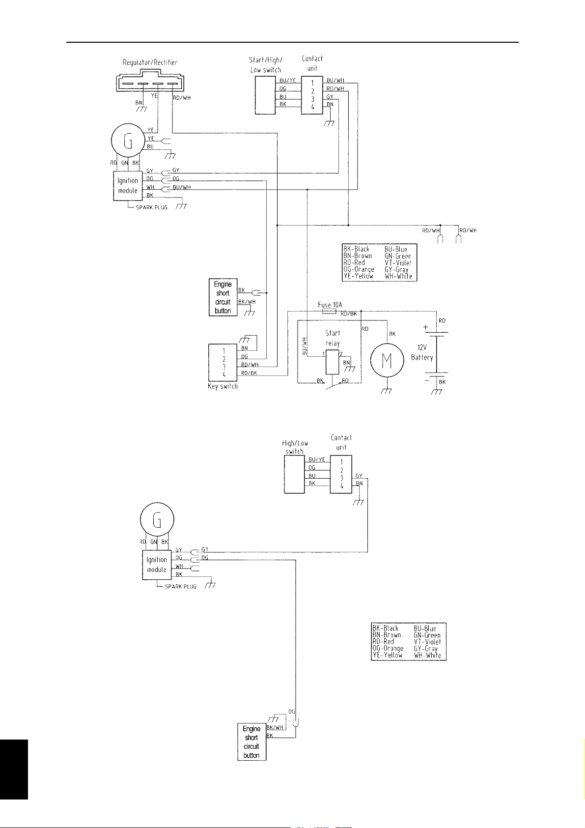
WIRING DIAGRAMS
FC and FX electrical starter models
12
FC and FS kick-starter models
34
 Loading...