

Page 1

GETTI NG STARTED WITH
WINMAX LATHE
January 2017 v546GS
Page 2

The information in this documen t is subject to change without notice and does not
repr esent a commitment on the part of Hurco Companies, Inc. (Hurco). The software
described in this document is furnished under the License Agreement to customers. It is
against the law to copy the software on any medium except as specifically allowed in the
license agreement. The purchaser may make copies of the software for backup purposes.
Hurco Manufacturing Company reserves the right to incorporate any modification or
improvements in machines and machine specifications which it considers necessary, and
does not assume any obligation to make any said changes in machines or equipment
previously sold.
Hurco products and services are subject to Hurco’s then current prices, terms, and
conditions, which are subject to change without notice.
© 2018 Hurco Companies, Inc. All rights reserved.
Patents:U.S. Patents B14,477,754; 5,453,933; Cana dian Patent 1,102,434; Japanese
Patents 1,649,006 and 1,375,124; other Patents pending.
Hurco, Max, Ultimax, and WinMax are Registered Trademarks of Hurco Companies, Inc.
AutoCAD, Autodesk, and DXF are registe red trademarks of Autodesk, Inc.
MS-DOS, Microsoft, and Windows are registered trademarks of Microsoft Corporation.
Many of the designations used by manufacturers and sellers to distinguish their products
are claimed as trademarks. Hurco has listed here all trademarks of which it is aware. For
more information about Hurco products and services, contact:
Hurco Companies, Inc.
One Technology Way
P.O. Box 68180
Indianapol is, IN 46268- 0180
For Hurco subsidiary contact information, go to Hurco’s Web site:
www.hurco.com
ii - Getting Started with WinMax Lathe v546GS Getting Started—WinMax Lathe Max Control
Page 3

TABLE OF CONTENTS
Getting Started with WinMax Lathe Dual-screen and Max Consoles
Documentation Conventions . . . . . . . . . . . . . . . . . . . . . . . . . . . . . . . . . . . . xi
Programming and Op eration Information . . . . . . . . . . . . . . . . . . . . . . . . . . . xiv
Using the On-screen Help . . . . . . . . . . . . . . . . . . . . . . . . . . . . . . . . . . . xiv
Printing the Programming Manuals . . . . . . . . . . . . . . . . . . . . . . . . . . . . . xv
Machine and Console Basics . . . . . . . . . . . . . . . . . . . . . . . . . . . . . . . . . . . . 1 - 1
Machine Components . . . . . . . . . . . . . . . . . . . . . . . . . . . . . . . . . . . . . . 1 - 2
Turret . . . . . . . . . . . . . . . . . . . . . . . . . . . . . . . . . . . . . . . . . . . . . . . 1 - 3
Parts Catcher . . . . . . . . . . . . . . . . . . . . . . . . . . . . . . . . . . . . . . . . . 1 - 3
Chip Conveyor . . . . . . . . . . . . . . . . . . . . . . . . . . . . . . . . . . . . . . . . . 1 - 3
Coolant Drip Tray . . . . . . . . . . . . . . . . . . . . . . . . . . . . . . . . . . . . . . . 1 - 3
Tailstock and Chuck Gauges . . . . . . . . . . . . . . . . . . . . . . . . . . . . . . . 1 - 3
Bar Feeder . . . . . . . . . . . . . . . . . . . . . . . . . . . . . . . . . . . . . . . . . . . 1 - 4
Consoles . . . . . . . . . . . . . . . . . . . . . . . . . . . . . . . . . . . . . . . . . . . . . . . 1 - 5
WinMax In terface Environment . . . . . . . . . . . . . . . . . . . . . . . . . . . . . . . . 1 - 6
Edit Mode . . . . . . . . . . . . . . . . . . . . . . . . . . . . . . . . . . . . . . . . . . . . 1 - 6
Full Precision Editing . . . . . . . . . . . . . . . . . . . . . . . . . . . . . . . . . . . . 1 - 7
Softkeys . . . . . . . . . . . . . . . . . . . . . . . . . . . . . . . . . . . . . . . . . . . . . 1 - 7
Drop-down Lists . . . . . . . . . . . . . . . . . . . . . . . . . . . . . . . . . . . . . . . 1 - 8
Expand and Collapse Files . . . . . . . . . . . . . . . . . . . . . . . . . . . . . . . . . 1 - 8
Sorting and Resizing Columns . . . . . . . . . . . . . . . . . . . . . . . . . . . . . . 1 - 9
Pop-up Messages . . . . . . . . . . . . . . . . . . . . . . . . . . . . . . . . . . . . . . . 1 - 9
Status Bar . . . . . . . . . . . . . . . . . . . . . . . . . . . . . . . . . . . . . . . . . . . 1 - 10
Pop-up Calculator . . . . . . . . . . . . . . . . . . . . . . . . . . . . . . . . . . . . 1 - 11
Pop-up Keyboard . . . . . . . . . . . . . . . . . . . . . . . . . . . . . . . . . . . . 1 - 11
On-screen Help . . . . . . . . . . . . . . . . . . . . . . . . . . . . . . . . . . . . . . . . 1 - 12
Accessing the WinMax Help in PDF format for printing . . . . . . . . . . . 1 - 13
Control Panel Function Groups . . . . . . . . . . . . . . . . . . . . . . . . . . . . . . . . 1 - 14
Machine Control . . . . . . . . . . . . . . . . . . . . . . . . . . . . . . . . . . . . . . . 1 - 14
Axis and Spindle Control . . . . . . . . . . . . . . . . . . . . . . . . . . . . . . . . . 1 - 16
Machine Operations . . . . . . . . . . . . . . . . . . . . . . . . . . . . . . . . . . . . . 1 - 18
Machine Mode . . . . . . . . . . . . . . . . . . . . . . . . . . . . . . . . . . . . . . 1 - 18
Coolant . . . . . . . . . . . . . . . . . . . . . . . . . . . . . . . . . . . . . . . . . . . 1 - 19
Spindle . . . . . . . . . . . . . . . . . . . . . . . . . . . . . . . . . . . . . . . . . . . 1 - 20
Turret . . . . . . . . . . . . . . . . . . . . . . . . . . . . . . . . . . . . . . . . . . . . 1 - 21
Jog Units . . . . . . . . . . . . . . . . . . . . . . . . . . . . . . . . . . . . . . . . . . . . . . . 1 - 22
Jog Unit Operation . . . . . . . . . . . . . . . . . . . . . . . . . . . . . . . . . . . . . . 1 - 22
Setting Jog Unit Parameters . . . . . . . . . . . . . . . . . . . . . . . . . . . . . . . 1 - 23
Max5 Rem ote Jog Units . . . . . . . . . . . . . . . . . . . . . . . . . . . . . . . . . . 1 - 24
Basic Remote Jog Unit . . . . . . . . . . . . . . . . . . . . . . . . . . . . . . . . . 1 - 24
Premium Remote Jog Unit . . . . . . . . . . . . . . . . . . . . . . . . . . . . . . 1 - 25
Max4 Rem ote Jog Unit . . . . . . . . . . . . . . . . . . . . . . . . . . . . . . . . . . . 1 - 27
Remote Jog Units . . . . . . . . . . . . . . . . . . . . . . . . . . . . . . . . . . . . 1 - 28
Enable Button . . . . . . . . . . . . . . . . . . . . . . . . . . . . . . . . . . . . . . . . . 1 - 30
Programming Keyb oard . . . . . . . . . . . . . . . . . . . . . . . . . . . . . . . . . . 1 - 31
Standard Keys . . . . . . . . . . . . . . . . . . . . . . . . . . . . . . . . . . . . . . 1 - 34
Cursor Control Keys . . . . . . . . . . . . . . . . . . . . . . . . . . . . . . . . . . 1 - 35
Special Function Keys . . . . . . . . . . . . . . . . . . . . . . . . . . . . . . . . . 1 - 35
Getting Started—WinMax Lathe Max Control v546GS T able of Cont ents — iii
Page 4

Numeric Keypad . . . . . . . . . . . . . . . . . . . . . . . . . . . . . . . . . . . . . .1 - 36
AT-Keyboard . . . . . . . . . . . . . . . . . . . . . . . . . . . . . . . . . . . . . . . .1 - 36
Draw Key . . . . . . . . . . . . . . . . . . . . . . . . . . . . . . . . . . . . . . . . . .1 - 37
Verify Key . . . . . . . . . . . . . . . . . . . . . . . . . . . . . . . . . . . . . . . . . .1 - 37
Communications Panel . . . . . . . . . . . . . . . . . . . . . . . . . . . . . . . . . . . . . .1 - 38
Utilities . . . . . . . . . . . . . . . . . . . . . . . . . . . . . . . . . . . . . . . . . . . . . . . . . . . .2 - 1
Utility Screen . . . . . . . . . . . . . . . . . . . . . . . . . . . . . . . . . . . . . . . . . . . . .2 - 2
System Configuration . . . . . . . . . . . . . . . . . . . . . . . . . . . . . . . . . . . . . . .2 - 3
Hour Meters . . . . . . . . . . . . . . . . . . . . . . . . . . . . . . . . . . . . . . . . . . .2 - 4
Machine Internet Protocol Address . . . . . . . . . . . . . . . . . . . . . . . . . . . .2 - 5
Hardware Configuration . . . . . . . . . . . . . . . . . . . . . . . . . . . . . . . . . . .2 - 5
Tool Setter Calibration . . . . . . . . . . . . . . . . . . . . . . . . . . . . . . . . .2 - 6
Auxiliary I/O Configuration . . . . . . . . . . . . . . . . . . . . . . . . . . . .2 - 6
Software Options . . . . . . . . . . . . . . . . . . . . . . . . . . . . . . . . . . . . . . . .2 - 8
Configuration Fil es . . . . . . . . . . . . . . . . . . . . . . . . . . . . . . . . . . . . . . .2 - 8
User Preferences . . . . . . . . . . . . . . . . . . . . . . . . . . . . . . . . . . . . . . . . . .2 - 10
User Interface Settings . . . . . . . . . . . . . . . . . . . . . . . . . . . . . . . . . . .2 - 10
Edit Lockout Mode—First Use . . . . . . . . . . . . . . . . . . . . . . . . . . . . .2 - 14
Setting Edit Lockout Level Preferences . . . . . . . . . . . . . . . . . . . .2 - 14
Reset Password . . . . . . . . . . . . . . . . . . . . . . . . . . . . . . . . . . . .2 - 14
Enable Edit Lockout Mode . . . . . . . . . . . . . . . . . . . . . . . . . . . . .2 - 15
Disable Edit Lockout Mode . . . . . . . . . . . . . . . . . . . . . . . . . . . .2 - 15
Conversational Settings . . . . . . . . . . . . . . . . . . . . . . . . . . . . . . . . . . .2 - 16
NC Settings . . . . . . . . . . . . . . . . . . . . . . . . . . . . . . . . . . . . . . . . . . .2 - 17
AutoSave Settings . . . . . . . . . . . . . . . . . . . . . . . . . . . . . . . . . . . . . . .2 - 18
Select Language . . . . . . . . . . . . . . . . . . . . . . . . . . . . . . . . . . . . . . . .2 - 19
Language Quick Toggle . . . . . . . . . . . . . . . . . . . . . . . . . . . . . . . . .2 - 19
Data Logging Filters . . . . . . . . . . . . . . . . . . . . . . . . . . . . . . . . . . . . . .2 - 20
Serial Port Settings . . . . . . . . . . . . . . . . . . . . . . . . . . . . . . . . . . . . . .2 - 21
Serial Port Setup . . . . . . . . . . . . . . . . . . . . . . . . . . . . . . . . . . . . .2 - 21
FTP Server Settings . . . . . . . . . . . . . . . . . . . . . . . . . . . . . . . . . . . . . .2 - 22
MMI Uptime . . . . . . . . . . . . . . . . . . . . . . . . . . . . . . . . . . . . . . . . . . .2 - 23
Printing . . . . . . . . . . . . . . . . . . . . . . . . . . . . . . . . . . . . . . . . . . . . . . . . .2 - 24
Integrator Support Services . . . . . . . . . . . . . . . . . . . . . . . . . . . . . . . . . . .2 - 25
Restart Control . . . . . . . . . . . . . . . . . . . . . . . . . . . . . . . . . . . . . . . . . . . .2 - 26
Shutdown Control . . . . . . . . . . . . . . . . . . . . . . . . . . . . . . . . . . . . . . . . . .2 - 26
Serial I/O . . . . . . . . . . . . . . . . . . . . . . . . . . . . . . . . . . . . . . . . . . . . . . .2 - 27
Log Files . . . . . . . . . . . . . . . . . . . . . . . . . . . . . . . . . . . . . . . . . . . . . . . .2 - 28
Accessing Log Files . . . . . . . . . . . . . . . . . . . . . . . . . . . . . . . . . . . . . .2 - 28
Retrieving Log Files . . . . . . . . . . . . . . . . . . . . . . . . . . . . . . . . . . . . . .2 - 29
Project Manager . . . . . . . . . . . . . . . . . . . . . . . . . . . . . . . . . . . . . . . . . . . . .3 - 1
Overview . . . . . . . . . . . . . . . . . . . . . . . . . . . . . . . . . . . . . . . . . . . . . . . .3 - 2
Managing Program Files . . . . . . . . . . . . . . . . . . . . . . . . . . . . . . . . . . . . .3 - 3
Create a New File . . . . . . . . . . . . . . . . . . . . . . . . . . . . . . . . . . . . . . .3 - 4
Open a File . . . . . . . . . . . . . . . . . . . . . . . . . . . . . . . . . . . . . . . . . . . .3 - 4
Save Fi les . . . . . . . . . . . . . . . . . . . . . . . . . . . . . . . . . . . . . . . . . . . . .3 - 5
Close a File . . . . . . . . . . . . . . . . . . . . . . . . . . . . . . . . . . . . . . . . . . . .3 - 6
Set Program Properties . . . . . . . . . . . . . . . . . . . . . . . . . . . . . . . . . . . . . .3 - 6
Use File Manager . . . . . . . . . . . . . . . . . . . . . . . . . . . . . . . . . . . . . . . . . .3 - 7
Folders . . . . . . . . . . . . . . . . . . . . . . . . . . . . . . . . . . . . . . . . . . . . . . .3 - 7
Files . . . . . . . . . . . . . . . . . . . . . . . . . . . . . . . . . . . . . . . . . . . . . . . . .3 - 8
Other Softkeys . . . . . . . . . . . . . . . . . . . . . . . . . . . . . . . . . . . . . . . . .3 - 8
Use the FTP Manager . . . . . . . . . . . . . . . . . . . . . . . . . . . . . . . . . . . . . . .3 - 9
iv - Table of Contents v546GS Getting Started—WinMax Lathe Max Control
Page 5

Programming Basics . . . . . . . . . . . . . . . . . . . . . . . . . . . . . . . . . . . . . . . . . . 4 - 1
Part Programming . . . . . . . . . . . . . . . . . . . . . . . . . . . . . . . . . . . . . . . . . 4 - 2
Planning . . . . . . . . . . . . . . . . . . . . . . . . . . . . . . . . . . . . . . . . . . . . . 4 - 5
Axes Movement . . . . . . . . . . . . . . . . . . . . . . . . . . . . . . . . . . . . . 4 - 5
Setup Screens . . . . . . . . . . . . . . . . . . . . . . . . . . . . . . . . . . . . . . 4 - 6
Part and Tool Loading . . . . . . . . . . . . . . . . . . . . . . . . . . . . . . . . . . . . . . 4 - 7
Loading the Workpiece . . . . . . . . . . . . . . . . . . . . . . . . . . . . . . . . . . . 4 - 7
Loading Live Tooling Tool Holders . . . . . . . . . . . . . . . . . . . . . . . . . . . 4 - 7
Loading Tools . . . . . . . . . . . . . . . . . . . . . . . . . . . . . . . . . . . . . . . . . 4 - 8
Two Axis (TM and TMX series) . . . . . . . . . . . . . . . . . . . . . . . . . . . 4 - 8
Live Tooling (TMM, TMXMY, an d TMXMYS series) . . . . . . . . . . . . . . 4 - 8
All series . . . . . . . . . . . . . . . . . . . . . . . . . . . . . . . . . . . . . . . . . . 4 - 8
Load Tools in Turret and Assign Tool Numbers . . . . . . . . . . . . . . . . 4 - 9
Part Setup—Work Offsets . . . . . . . . . . . . . . . . . . . . . . . . . . . . . . . . . . . . 4 - 11
Part Setup Fields . . . . . . . . . . . . . . . . . . . . . . . . . . . . . . . . . . . . . . . 4 - 14
Part Setup Softkeys . . . . . . . . . . . . . . . . . . . . . . . . . . . . . . . . . . . . . 4 - 16
Tool Setup—Geometry Offsets . . . . . . . . . . . . . . . . . . . . . . . . . . . . . . . . 4 - 17
Turning Tool Setup Fields . . . . . . . . . . . . . . . . . . . . . . . . . . . . . . . . . 4 - 20
Custom . . . . . . . . . . . . . . . . . . . . . . . . . . . . . . . . . . . . . . . . . . . 4 - 21
Turning . . . . . . . . . . . . . . . . . . . . . . . . . . . . . . . . . . . . . . . . . . . 4 - 23
Boring . . . . . . . . . . . . . . . . . . . . . . . . . . . . . . . . . . . . . . . . . . . . 4 - 25
Center Drill . . . . . . . . . . . . . . . . . . . . . . . . . . . . . . . . . . . . . . . . 4 - 28
Drill . . . . . . . . . . . . . . . . . . . . . . . . . . . . . . . . . . . . . . . . . . . . . . 4 - 29
Threading . . . . . . . . . . . . . . . . . . . . . . . . . . . . . . . . . . . . . . . . . 4 - 31
Grooving . . . . . . . . . . . . . . . . . . . . . . . . . . . . . . . . . . . . . . . . . . 4 - 32
Cutoff . . . . . . . . . . . . . . . . . . . . . . . . . . . . . . . . . . . . . . . . . . . . 4 - 35
Back Turning . . . . . . . . . . . . . . . . . . . . . . . . . . . . . . . . . . . . . . . 4 - 37
Back Boring . . . . . . . . . . . . . . . . . . . . . . . . . . . . . . . . . . . . . . . . 4 - 39
Tap . . . . . . . . . . . . . . . . . . . . . . . . . . . . . . . . . . . . . . . . . . . . . . 4 - 42
Ream . . . . . . . . . . . . . . . . . . . . . . . . . . . . . . . . . . . . . . . . . . . . 4 - 43
Inserted Drill . . . . . . . . . . . . . . . . . . . . . . . . . . . . . . . . . . . . . . . 4 - 44
Live-Tooling Tool Setup Fields . . . . . . . . . . . . . . . . . . . . . . . . . . . . . . 4 - 47
End Mill . . . . . . . . . . . . . . . . . . . . . . . . . . . . . . . . . . . . . . . . . . . 4 - 47
Ball End Mill . . . . . . . . . . . . . . . . . . . . . . . . . . . . . . . . . . . . . . . . 4 - 50
Bull Nose Mill . . . . . . . . . . . . . . . . . . . . . . . . . . . . . . . . . . . . . . . 4 - 52
Live Center Drill . . . . . . . . . . . . . . . . . . . . . . . . . . . . . . . . . . . . . 4 - 54
Live Drill . . . . . . . . . . . . . . . . . . . . . . . . . . . . . . . . . . . . . . . . . . 4 - 56
Live Tap . . . . . . . . . . . . . . . . . . . . . . . . . . . . . . . . . . . . . . . . . . 4 - 58
Live Ream . . . . . . . . . . . . . . . . . . . . . . . . . . . . . . . . . . . . . . . . . 4 - 60
Live Custom . . . . . . . . . . . . . . . . . . . . . . . . . . . . . . . . . . . . . . . . 4 - 62
Tool Setup Softkeys . . . . . . . . . . . . . . . . . . . . . . . . . . . . . . . . . . . . . 4 - 65
Tool Geometry Offsets . . . . . . . . . . . . . . . . . . . . . . . . . . . . . . . . . . . 4 - 67
Tool Geometry Offsets Fields . . . . . . . . . . . . . . . . . . . . . . . . . . . . 4 - 67
Tool Geometry Offsets Softkeys . . . . . . . . . . . . . . . . . . . . . . . . . . 4 - 68
Measuring Tool Offsets . . . . . . . . . . . . . . . . . . . . . . . . . . . . . . . . 4 - 70
Tool Wear Offsets . . . . . . . . . . . . . . . . . . . . . . . . . . . . . . . . . . . . . . 4 - 74
Tool Wear Offset Fields . . . . . . . . . . . . . . . . . . . . . . . . . . . . . . . . 4 - 74
Tool Wear Offset Softkeys . . . . . . . . . . . . . . . . . . . . . . . . . . . . . . 4 - 75
Automat ic Feed and Speed Calculations . . . . . . . . . . . . . . . . . . . . . . . 4 - 76
Entering Zero for Speed (RPM) Value . . . . . . . . . . . . . . . . . . . . . . 4 - 76
Entering Actual Speed (RPM) Value . . . . . . . . . . . . . . . . . . . . . . . . 4 - 76
Formulas for Automatic Calculations . . . . . . . . . . . . . . . . . . . . . . . 4 - 76
Tool Rev iew . . . . . . . . . . . . . . . . . . . . . . . . . . . . . . . . . . . . . . . . . . . . . 4 - 77
Edit from the Tool Review Screen . . . . . . . . . . . . . . . . . . . . . . . . . . . 4 - 78
Program Parameters . . . . . . . . . . . . . . . . . . . . . . . . . . . . . . . . . . . . . . . 4 - 82
Getting Started—WinMax Lathe Max Control v546GS Table of Contents — v
Page 6

Verifying Part Programs—Graphics . . . . . . . . . . . . . . . . . . . . . . . . . . . . . .4 - 86
Max5 Graphics Screen Controls . . . . . . . . . . . . . . . . . . . . . . . . . . . . . .4 - 88
Graphics Settings . . . . . . . . . . . . . . . . . . . . . . . . . . . . . . . . . . . . . . .4 - 89
Display Settings . . . . . . . . . . . . . . . . . . . . . . . . . . . . . . . . . . . . . .4 - 89
Performance Settings . . . . . . . . . . . . . . . . . . . . . . . . . . . . . . . . . .4 - 90
Machine Configuration . . . . . . . . . . . . . . . . . . . . . . . . . . . . . . . . . .4 - 90
Programming Training . . . . . . . . . . . . . . . . . . . . . . . . . . . . . . . . . . . . . . .4 - 91
Machine Operation Basics . . . . . . . . . . . . . . . . . . . . . . . . . . . . . . . . . . . . . . .5 - 1
Power Up . . . . . . . . . . . . . . . . . . . . . . . . . . . . . . . . . . . . . . . . . . . . . . . .5 - 2
Routine Daily Checks . . . . . . . . . . . . . . . . . . . . . . . . . . . . . . . . . . . . .5 - 2
Machine Power . . . . . . . . . . . . . . . . . . . . . . . . . . . . . . . . . . . . . . . . .5 - 2
Control Power . . . . . . . . . . . . . . . . . . . . . . . . . . . . . . . . . . . . . . . . . .5 - 3
Calibrate the Machine . . . . . . . . . . . . . . . . . . . . . . . . . . . . . . . . . . . .5 - 3
Home the Machine . . . . . . . . . . . . . . . . . . . . . . . . . . . . . . . . . . . . . . .5 - 5
Warm Up the Machine and Spindle . . . . . . . . . . . . . . . . . . . . . . . . . . .5 - 5
Jogging the Axes Man ually . . . . . . . . . . . . . . . . . . . . . . . . . . . . . . . . . . . .5 - 6
Indexing the Turret using Console Keys . . . . . . . . . . . . . . . . . . . . . . . . . .5 - 6
Manual Mode Operation . . . . . . . . . . . . . . . . . . . . . . . . . . . . . . . . . . . . . .5 - 7
Two-Axis (TM Series) . . . . . . . . . . . . . . . . . . . . . . . . . . . . . . . . . . . . .5 - 8
TM Series Manual Screen Fiel ds . . . . . . . . . . . . . . . . . . . . . . . . . . .5 - 8
TM Series Manual Screen Softkeys . . . . . . . . . . . . . . . . . . . . . . . . .5 - 10
Live Tooling (TMM Series) . . . . . . . . . . . . . . . . . . . . . . . . . . . . . . . . . .5 - 11
TMM Series Manual Screen Fields . . . . . . . . . . . . . . . . . . . . . . . . . .5 - 11
TMM Series Manual Screen Softkeys . . . . . . . . . . . . . . . . . . . . . . . .5 - 13
Two-Axis Programmable Tailstock (TMX Series) . . . . . . . . . . . . . . . . . .5 - 14
TMX Series Manual Screen Fields . . . . . . . . . . . . . . . . . . . . . . . . . .5 - 14
TMX Series Manual Screen Softkeys . . . . . . . . . . . . . . . . . . . . . . . .5 - 15
Live-Tooling and Y-Axis Motion (TMX MY Series) . . . . . . . . . . . . . . . . . .5 - 17
TMX MY Series Manual Screen Fields . . . . . . . . . . . . . . . . . . . . . . . .5 - 17
TMX MY Series Manual Screen Softkeys . . . . . . . . . . . . . . . . . . . . . .5 - 19
Live-Tooling, Y-Axis Motion, and Sub-spindle (TMX MYS Series) . . . . . . .5 - 20
TMX MYS Series Manual Screen Fields . . . . . . . . . . . . . . . . . . . . . . .5 - 20
TMX MYS Series Manual Screen Softkeys . . . . . . . . . . . . . . . . . . . . .5 - 22
Set Active Tool . . . . . . . . . . . . . . . . . . . . . . . . . . . . . . . . . . . . . . . . .5 - 23
Setting Jog Unit Parameters . . . . . . . . . . . . . . . . . . . . . . . . . . . . . . . .5 - 23
Manual Function Setup Softkeys . . . . . . . . . . . . . . . . . . . . . . . . . . .5 - 24
Diagnostics . . . . . . . . . . . . . . . . . . . . . . . . . . . . . . . . . . . . . . . . . . . .5 - 24
Turret Di agnostics . . . . . . . . . . . . . . . . . . . . . . . . . . . . . . . . . . . .5 - 24
TM Series Machines . . . . . . . . . . . . . . . . . . . . . . . . . . . . . . . . .5 - 25
TM Series Turret Diagnostics Fields . . . . . . . . . . . . . . . . . . . . . .5 - 25
TM Series Turret Diagnostics Softkeys . . . . . . . . . . . . . . . . . . . .5 - 27
TMM Series Machines . . . . . . . . . . . . . . . . . . . . . . . . . . . . . . . .5 - 28
TMM Series Turret Di agnostics Fields . . . . . . . . . . . . . . . . . . . . .5 - 28
TMM Series Turret Diagnostics Softkeys . . . . . . . . . . . . . . . . . . .5 - 30
TMX Series Machines . . . . . . . . . . . . . . . . . . . . . . . . . . . . . . . .5 - 32
TMX Turret Diagnostics Fields . . . . . . . . . . . . . . . . . . . . . . . . . .5 - 32
TMX Series Turret Diagnostics Softkeys . . . . . . . . . . . . . . . . . . .5 - 33
TMX MY and TMX MYS Series Machines . . . . . . . . . . . . . . . . . . .5 - 35
TMX MY and TMX MYS Turret Diagnostics Fields . . . . . . . . . . . . .5 - 35
TMX MY and TMX MYS Series Turret Diagnostics Softkeys . . . . . .5 - 37
Lube Diagnostics . . . . . . . . . . . . . . . . . . . . . . . . . . . . . . . . . . . . .5 - 38
Axis Limit Switches . . . . . . . . . . . . . . . . . . . . . . . . . . . . . . . . . . . .5 - 39
CE Diagnostics . . . . . . . . . . . . . . . . . . . . . . . . . . . . . . . . . . . . . . .5 - 39
Entering the Access Code . . . . . . . . . . . . . . . . . . . . . . . . . . . . .5 - 40
vi - Table of Contents v546GS Getting Started—WinMax Lathe Max Control
Page 7

Changing an Existing Access Code . . . . . . . . . . . . . . . . . . . . . . 5 - 41
Manual Safety Override Mode . . . . . . . . . . . . . . . . . . . . . . . . . 5 - 41
Input/Output Diagnostics . . . . . . . . . . . . . . . . . . . . . . . . . . . . . . . 5 - 42
Manual Turret Operation for TMX MY and TMX MYS Series Machines . 5 - 43
Turret Overload Clutch and Live Tool . . . . . . . . . . . . . . . . . . . . 5 - 43
Turret Overload Clutch and Tool Disc Rotation . . . . . . . . . . . . . . 5 - 44
Tool Disc Rotation Spline Driver Alignment . . . . . . . . . . . . . . . . 5 - 45
Accessory Operations . . . . . . . . . . . . . . . . . . . . . . . . . . . . . . . . . . . . 5 - 47
Steady R est Lubrication Diagnostics . . . . . . . . . . . . . . . . . . . . . . . 5 - 47
Steady R est Lube Diagnostics Fields . . . . . . . . . . . . . . . . . . . . . 5 - 48
Chuck Operations . . . . . . . . . . . . . . . . . . . . . . . . . . . . . . . . . . . . . . 5 - 48
Auto Mode Operation . . . . . . . . . . . . . . . . . . . . . . . . . . . . . . . . . . . . . . . 5 - 52
Auto (Conversational) Screen Fields . . . . . . . . . . . . . . . . . . . . . . . . . . 5 - 53
Auto Run Screen Softkeys . . . . . . . . . . . . . . . . . . . . . . . . . . . . . . . . . 5 - 55
Operate the Optional Chip Conveyor . . . . . . . . . . . . . . . . . . . . . . . 5 - 55
Monitor the NC Codes . . . . . . . . . . . . . . . . . . . . . . . . . . . . . . . . . 5 - 55
Adjust the Tool Position . . . . . . . . . . . . . . . . . . . . . . . . . . . . . . . . 5 - 55
Adjust the Auto Run Graphics . . . . . . . . . . . . . . . . . . . . . . . . . . . . 5 - 55
Adjust the Realtime Graphics Settings . . . . . . . . . . . . . . . . . . . . . . 5 - 55
Turn the Worklight On or Off . . . . . . . . . . . . . . . . . . . . . . . . . . . . 5 - 55
Auto Run Screen Fields . . . . . . . . . . . . . . . . . . . . . . . . . . . . . . . . . . . 5 - 55
TM Series Auto Run Fields . . . . . . . . . . . . . . . . . . . . . . . . . . . . . . 5 - 56
TMM Series Auto Run Fields . . . . . . . . . . . . . . . . . . . . . . . . . . . . . 5 - 57
TMX Series Auto Run Fields . . . . . . . . . . . . . . . . . . . . . . . . . . . . . 5 - 58
TMX MY Series Auto Run Fields . . . . . . . . . . . . . . . . . . . . . . . . . . . 5 - 59
TMX MYS Series Auto Run Fields . . . . . . . . . . . . . . . . . . . . . . . . . . 5 - 60
Running a Program . . . . . . . . . . . . . . . . . . . . . . . . . . . . . . . . . . . . . . . . 5 - 62
Automat ic Machine Operation . . . . . . . . . . . . . . . . . . . . . . . . . . . . . . 5 - 63
Run the Program Block by Block . . . . . . . . . . . . . . . . . . . . . . . 5 - 63
Stop Automatic Machine Operation . . . . . . . . . . . . . . . . . . . . . . . . . . 5 - 64
Shut Down the Control and Machine . . . . . . . . . . . . . . . . . . . . . . . . . . . . 5 - 65
Record of Changes . . . . . . . . . . . . . . . . . . . . . . . . . . . . . . . . . . . . . . . . . . . I
Index . . . . . . . . . . . . . . . . . . . . . . . . . . . . . . . . . . . . . . . . . . . . . . . . . . . . I
Getting Started—WinMax Lathe Max Control v546GS Table of Contents — vii
Page 8

- viii Table of Contents v546GS Getting Started—WinMax Lathe Max Control
Page 9

DOCUMENTATION CONVENTIONS
This documentation uses several conventions to explain the safety features and
emphasize key concepts. These conventions are described in this section.
Sample Scree ns
Sample screens in this documentation were taken from a WinMax single-screen contr ol.
All screens are subject to change. The screens on your system may vary slightly.
Softkeys
Softkeys are located on the side of the screen. You can set the softkeys to appear on
either the right or left side of the screen. Refer to the Getting Started with WinMax for
information about making this selection. Softkeys may change upon field entries or other
softkey selection. References to softkeys in the documentation appear with the softkey’s
correspo nding F-key. For example, the Part Setup softkey from the Input screen is
referenced as the PART SETUP F1 softkey.
Screen A reas
The screens are divided into the following areas, in addition to the row of softkeys:
Data Entry
The data entry area is located on the opposite side of the screen from the softkeys.
Available softkeys may change even when the text and data entry area does not.
Fields in the d ata entry area display or receive information. Refer to Using the
Touchscreen for information on entering information in fields.
Prompts and Error/Status Area
The bottom portion of the screen is reserved for prompts, program status and error
messages.
Prompts provide help on data entry selections based on the field with the blinking cursor.
Errors and status messages occur anytime the status or error occur s. They are not based
on the field with the blinking cursor. These messages provide machine information to the
operator.
Error mess ages may also stop and/or prevent m achine operation until the cause of the
error is corrected.
Status Bar
The status bar contains
Getting Started—WinMax Lathe Max Control v546GS Documentation Conventions — xi
Page 10

• The name of the open, selected program.
• A calculator icon—select the icon to display a working, on-screen calcul ator.
• Units of measu re (Inch or Millimeters)—select the units of measure in the
status bar to toggle between Inch and Metric.
• Programming mode (R for Radius; D for Diameter)—select the programming
mode in the status bar to toggle between Radius and Diameter.
• A yellow icon—indicates the feed hold is on when visible.
• A red icon—indicates the Emergency Stop butto n has been pressed when
visible.
• A keyboard icon—select the icon to display a working on-screen keyboard.
• The current time.
When viewed on a single-screen console, all icons appear in the same status bar; when
viewed on a dual-screen console, the program name and calculator icon appear on the
left screen status bar, and the unit of measure, keyboard icon and time appear on the
right screen status bar.
Conso le Buttons and Keys
References to console buttons and keys appear in bold text throughout the
documentation. For example, the Start Cycle button appears as the Start Cyc le button
and the Manual key appears as the Manual console key in text.
Refer to the Getting Started with Wi nMax manual for information about console buttons
and keys, in addition to other information about using softkeys and the pop-up text entry
window.
Using the Touchscreen
The console has a touchscreen for entering programming data. To make a selection, tap
the screen on a softkey, field, or drop-down list using the stylus attached to the side of
the console or another suitable pointing device.
Icons
This manual may contain the following icons:
Caution/W arning
The operator may be injured and/or the machine severely damaged if the
described procedure is not followed.
xii - Documentation Conventions v546GS Getting Started—WinMax Lathe Max Control
Page 11

Important
Ensures proper operation of the machine and control.
Troubleshooting
?
Hints and Tricks
Where can we go from here?
Step s that can be taken to solve potential problems.
Useful suggestions that show creative uses of the WinMax features.
Lists several possible options the operator can take.
Getting Started—WinMax Lathe Max Control v546GS Documentation Conventions — xiii
Page 12

PROGRAMMING AND OPERATION
NFORMATION
I
Hurco provides documentation for using WinMax software on a control or desktop in two
formats: on-screen Help and PDF. The information contained in both formats is identical.
On-screen Help contains information about the current screen. If Help is not available for
a screen, a Welcome screen appears with access to the Table of Contents, Index, or
Search functions.
• To view the o n-screen Help directly on a Hurc o c ontrol, select the Help
console key.
• To view the on-screen Help on the desktop software, select the Help icon in
the menu bar.
PDF files are available on the hard drive. These files can be copied from the hard drive to
a USB memory device and transferred to a PC for viewing and printing.
Using the O n -screen Help
On-scr een Help provides information about using WinMax. The Help is context-sensitive
to the screen level. Press the console Help button to display the Help topic for the current
screen. The following list describes Help functions:
• Buttons in the upper left-hand corner of the Help screen are used to move
throu g h Help topics and print screens.
•Use the Hide button to hide the navigation pane.
•Use the Back button to return to the previous Help screen.
•Use the Print button to print the current displayed Help topic, i f a printer
is attached and configured. See Printing the Programming Manuals, on
page - xv for more information about printing.
• Use the arrow buttons to move between pages within a Help to pic and to
move through topics.
•Use the Contents tab for a list of information sorted by subject:
1. Select the “+” to expand the topic and view sub-topics.
2. Select the topic to display it.
•Use the Index tab to show the Help index:
1. Qui ckly scroll to an index topic by typing the topic in the box at the top of
the index.
2. Select a topic and the Display button to view the topic.
xiv - Programming and Operation Information v546GS Getting Started—WinMax Lathe Max Control
Page 13

•Use the Search tab to search the Help for a w ord or phrase:
1. Type the search word(s) into the text box at the top of the pane.
2. S e lec t the Li st T opi cs bu t to n. A li st of to p ic s th a t co nt ai n t h e se ar ch word ( s)
is displayed.
3. Select a topic and the Display button to view that topic.
•Use the Favorites tab to save Help topics for quick access:
1. Select the Add button at the bottom of the pane to add the current topic.
2. Select a topic from the Favorites list, and select the Display button to view
it.
• Select a topic from the Favorites list, and select the Remove button to
remove it from the list.
Printing the Programming Manuals
The WinMax On-screen Help is also provided in PDF format for easy printing. The
informati on contained in the PDF fil es is identica l to the on-screen Help. Th e PDF files may
be copied to a floppy disk or USB memory device to be transferred to a PC for prin ting.
Here are the steps to access the PDF files:
1. From the Input screen, select the PROJECT MANAGER F8 softkey.
2. Select the FILE MANAGER F7 softkey.
3. In the left-hand pane, navigate t hrough the folders:
• For WinMax Lathe on a machine, the path is D:\H urco\Hurco Lathe\hlp.
• For WinMax Desktop on a PC, the path is C:\Program Files\Hurco\Hurco
Lathe\hlp.
The PDF files will appear in the right-hand pane.
The SHOW ALL FILE TYPES field in User Interface Settings must be
set to YES (default is NO) in order to see the PDF files in the
directory. Access the SHOW ALL FILE TYPES field in Auxiliary Mode,
Utilities/ User Preferences/ User Interface Settings.
4. Highlight the PDF file(s) in the rig ht-hand pane, and select the COPY F2
softkey.
5. Ensure that your media is loaded (either a floppy disk in the disk drive or a USB
memory devic e in the USB port), and navigate to the pro per location in the lefthand pane of the DISK OPERATIONS screen (either the floppy drive A: or the
USB port E:). Highlight the desired location.
6. Place the cursor in the right-hand pane and select the PASTE F3 softkey to
paste the PDF file(s) to the desired location.
You may now remove your media and load the PDF file(s) onto a PC for printing.
Getting Started—WinMax Lathe Max Control v546GS Programming and Operation Information — xv
Page 14

xvi - Programming and Operation Information v546GS Getting Started—WinMax Lathe Max Control
Page 15

MACH INE AND CONSOLE BASICS
This section explains basic machine and console features.
Machine Components . . . . . . . . . . . . . . . . . . . . . . . . . . . . . . . . . . . . . . . . 1 - 2
Turret . . . . . . . . . . . . . . . . . . . . . . . . . . . . . . . . . . . . . . . . . . . . . . . . 1 - 3
Parts Catcher . . . . . . . . . . . . . . . . . . . . . . . . . . . . . . . . . . . . . . . . . . . 1 - 3
Chip Conveyor. . . . . . . . . . . . . . . . . . . . . . . . . . . . . . . . . . . . . . . . . . . 1 - 3
Coolant Drip Tray . . . . . . . . . . . . . . . . . . . . . . . . . . . . . . . . . . . . . . . . 1 - 3
Tailstock and Chuck Gauges . . . . . . . . . . . . . . . . . . . . . . . . . . . . . . . . . 1 - 3
Bar Feeder . . . . . . . . . . . . . . . . . . . . . . . . . . . . . . . . . . . . . . . . . . . . . 1 - 4
Consoles . . . . . . . . . . . . . . . . . . . . . . . . . . . . . . . . . . . . . . . . . . . . . . . . . 1 - 5
WinMax Interface Environment. . . . . . . . . . . . . . . . . . . . . . . . . . . . . . . . . . 1 - 6
Control Panel Function Groups . . . . . . . . . . . . . . . . . . . . . . . . . . . . . . . . . . 1 - 14
Machine Control . . . . . . . . . . . . . . . . . . . . . . . . . . . . . . . . . . . . . . . . . 1 - 14
Axis and Spindle Control. . . . . . . . . . . . . . . . . . . . . . . . . . . . . . . . . . . . 1 - 16
Machine Operations . . . . . . . . . . . . . . . . . . . . . . . . . . . . . . . . . . . . . . . 1 - 18
Jog Units . . . . . . . . . . . . . . . . . . . . . . . . . . . . . . . . . . . . . . . . . . . . . . 1 - 22
Programming Keyboard . . . . . . . . . . . . . . . . . . . . . . . . . . . . . . . . . . . . 1 - 31
Communications Panel . . . . . . . . . . . . . . . . . . . . . . . . . . . . . . . . . . . . . . . 1 - 38
Getting Started—WinMax Lathe Max Control v546GS Machine and Console Basics 1-1
Page 16
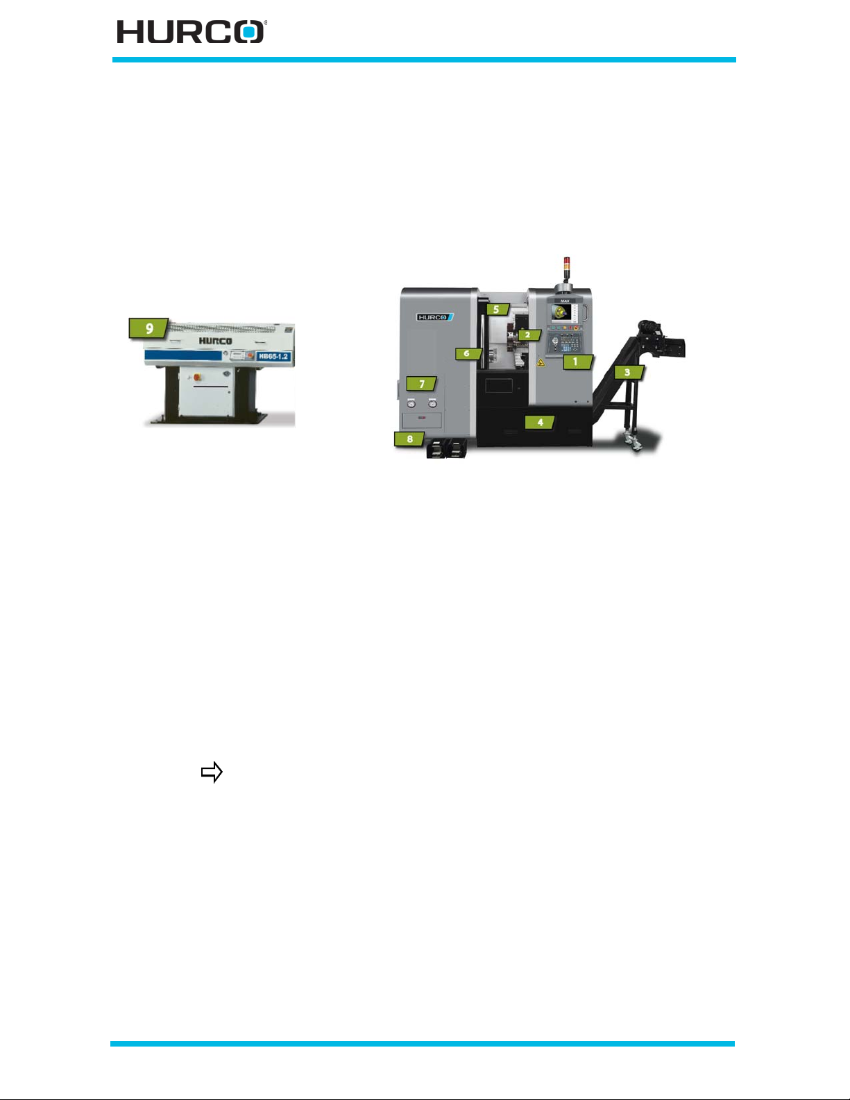
Machi ne Components
Before using the machine, you should become familiar with its components. Because of
European Committee (CE) requirements, Hurco machines sold in Europe may differ from
those sold elsewhere. The figure below identifies some of the easily recognized
components of a machine. The location of some components may differ on other models.
1 Console
2 Turret
3 Conveyor option
4 Coolant Drip Tray
5 Enclosure Door
6 Spindle
Figure 1–1. Bar Feeder next to a TM6 Turning Center with Options
Hurco machines are available with several hardware and software options.
Information about options is available from Hurco or your Hurco
distributor.
7
Tailstock/Chuck Gauge options
8 Tailstock/Chuck Footswitch options
9 Bar Feeder option
1 - 2 Machine and Console Basics v546GS Getting Started—WinMax Lathe Max Control
Page 17

Turret
Hurco turning centers use a turret to hold tools. Each tool is manually inserted into the
turret.
• The turret contains boring blocks for holding tools and turning stations for
holding turning tools.
• Bolts secure tools inserted in boring blocks; wedge clamps secure tools in
their stations.
• Turret stations are numbered to identify and locate each too l.
• Use the Turret + (Plus) or - (Minus) console keys to increment or decrement
the tool station.
Tools in the turret are described and programmed during Tool Setup. Refer to Tool
Setup—Geometry Offsets, on page 4 - 17 for programming information.
Part s Catcher
The optional Parts Catcher holds a pa rt after it has been cut. Yo u can open the Parts
Catcher door to take the part out while the next part is b eing cut. Refer to WinMax Lathe
Options Parts Catcher, on page 10 - 1 for information about this option. Refer to the
Maintenance and Safety Manual for information about the pneumatic system
maintenance for this option.
Chip Conveyor
An optional chip conveyor is available for moving the scrap pieces of metal out of the
machine. Chips that are not flushed out of the machine collect in the chip conveyor tank.
Refer to WinMax Lathe Options Chip Conveyor, on p a ge 4 - 1 for information about this
option. Refer to the Maintenanc e and Safety Manual for information about tank and
screen maintenance.
Coolant Drip Tray
The coolant drip tray is located under the machine. This removable tray collects the
coolant as it drips during machine operation.
Tailstock and Chuck Gauges
The optional tailstock balances long pieces of stock while the spindle is turning and the
piece is b e ing cut. The tailstock touches the loose end of the stock, on the right-hand
side, while the chuck holds the stock at the other end. The optional tailstock and chuck
operate using hydraul ics. The gauges show the hyd raulic press ure. Refer t o WinMax Lath e
Options Tailstock Assembly, on page 14 - 1 and Collet Chuck, on page 5 - 1 for
information about these options. Refer to the Maintenance and Safety Manual for
information about hydraulic pressure setting.
Getting Started—WinMax Lathe Max Control v546GS Machine and Console Basics 1-3
Page 18

Bar Feeder
The optional bar feeder places stock into the spindle, through hole in the left side of the
machine. As the stock is cut, the feeder replaces it with a new piece as necessary. You
can program a tool with a Bar Feed Block to pull th e stock away from the feeder. Refer to
WinMax Lathe Options Bar Feeder, on page 3 - 1 for information about this option.
1 - 4 Machine and Console Basics v546GS Getting Started—WinMax Lathe Max Control
Page 19
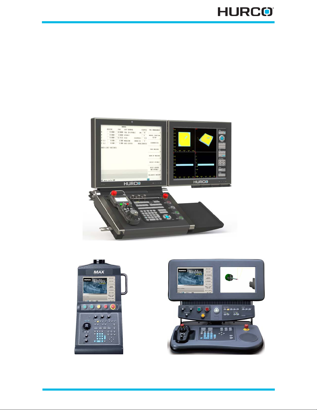
Consoles
The console, and the electri cal components requ ired to operate it, are called the “control”
or the “CNC” (Computer Numeric Control). Some electrical components are built into a
separate enclosure kept in the machine’s electrical cabinet. Some internal components,
such as drives and memory, are like those in a PC. Only the parts of the Windows®
operating system that are necessary to run Hurco CNCs are used. Customers are not
permitted to install software on the WinMax control. Pictured below are the Max5 dual-,
Max4 dual-, and Max4 single-screen consoles.
Ma x5 dual-screen c o nsole
Figure 1–2. Max Console and Dual-screen Console
Getting Started—WinMax Lathe Max Control v546GS Machine and Console Basics 1-5
Page 20
WinMax Interface Environment
There are three ways to navigate and enter data for programming:
• Touchscreen—use the stylus or other pointing device to select softkeys and
drop-down lists for data entry and programming.
• Keyboard—use the function (F1-F12) keys and other keyboard shortcuts for
navigation and to call up screens.
• Ultimax classic edit mo de—use the console keys; for example, use the
arrow keys for navigation and the enter key to accept data typed into a field.
See Edit Mode below for more information.
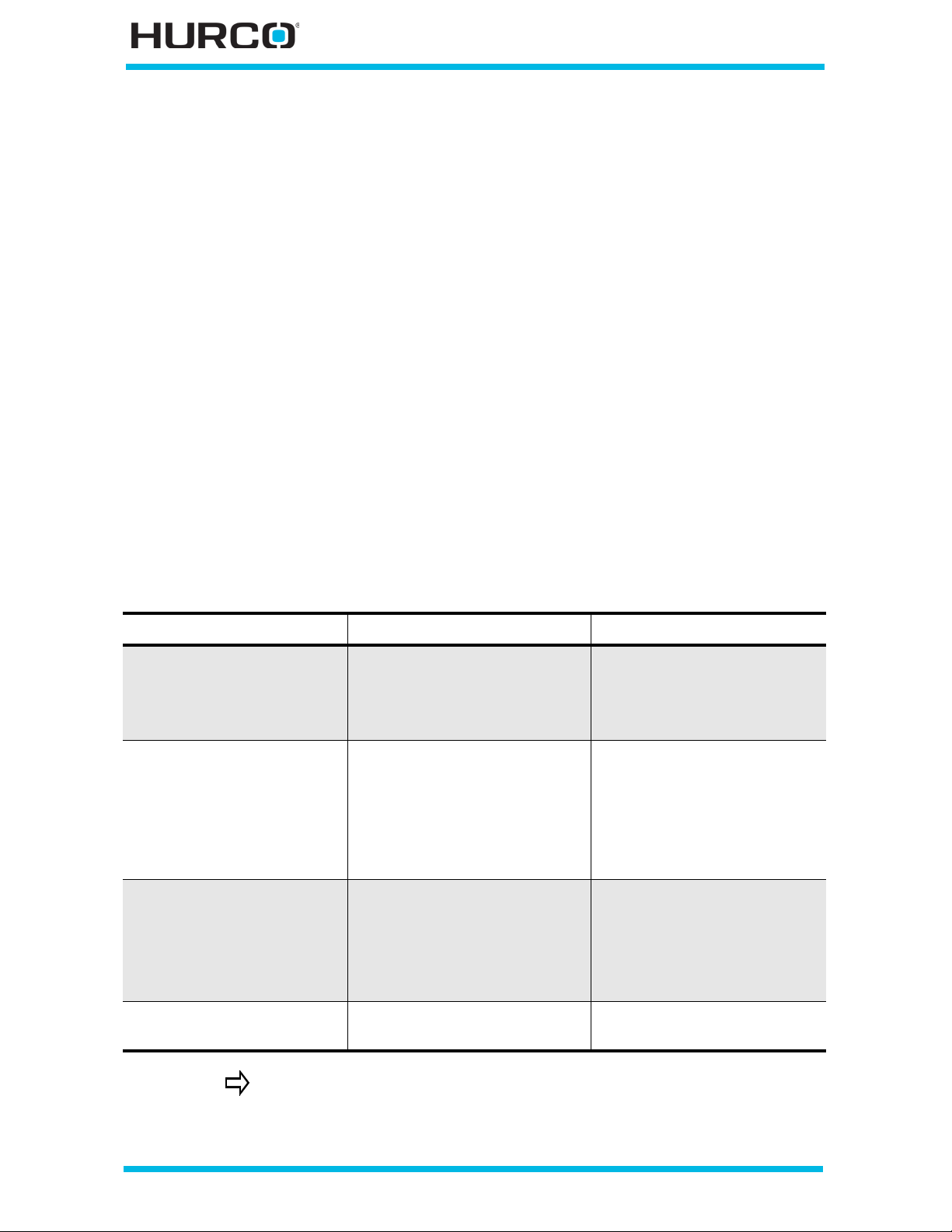
Edit Mode
Edit Mode i s set in Utilities . Refer to User Interface Settings, on page 2 - 10. WinM ax has
two edit modes:
• Ultimax Classic (default)—in this mode the console arrow keys are used to
move b etween bloc ks and segments , and the En ter key is used to accep t data
after it is typed into a field.
• Windows Dialog—in this mode the console arrow keys do not navigate
through fields and the Enter key is not required to accept data typed into a
field.
If you want to... Ultimax Classic Windows Dialog
Enter data into a field Enter key to accept data Enter key to accept data
OR
Down (or Up) arrow to
accept data
Advance to next block Right/Left arrows
OR
Next Block/Previous B lock
softkeys
OR
Page Up or Page Down key
Advance to next segment
or ope r at i on
Navigate to next or
previou s tool in Tool Setup
The right and left arrows will change the selection in fields with dropdown li sts (suc h as Tool Type in Tool Setup) in either Ultimax Classic
or Windows Dial og mode.
Right/Left arrows
OR
Next segment/hole softkeys
OR
Page Up or Page Down key
Left or right arrow keys Page Up or Page Down keys
Next Block/Previous Bloc k
softkeys
OR
Page Up or Page Down key
Next segment/hole softkeys
OR
Page Up or Page Down key
1 - 6 Machine and Console Basics v546GS Getting Started—WinMax Lathe Max Control
Page 21
Full Precision Editing
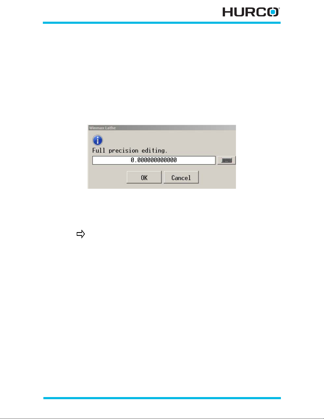
Numbers with decimals are rounded to the decimal display limit (three digits for metric
and four digits for imperial) when displayed in a field. Full Precision Editing allows you to
view the full number (up to 12 digits after the decimal) and to edit it to a more precise
point.
To open a pop-up box containing the number, put the cursor in a numeric decimal field:
• On the console press F + decimal (.).
• On the desktop press Ctrl + decimal (.).
Figure 1–3. Full Precision Editing Pop-up Box
Edit the number and select OK to save the changes. To close the pop-up box without
saving changes, select Cancel.
Do not use Full Precision Editing to change numbers that are
automatically calculated by WinMax. These numbers are calculated
to their 12-digit maximum accuracy and changing them could result
in changes to other automatic calculations in the program.
Softkeys
Softkeys have a three-dimensional look on the touch screen of the console. Each softkey
is labeled with an operation. Touching the softkey selects its operation.
If a softkey appears “graye d out,” the operation is not available because the cursor is not
in a specific field or the machine does not support the feature.
Softkeys appear as buttons on the screen; their default location is the right side of the
screen, but they can also be positioned on the left by changing the setting in User
Preferences (see Utilities, on page 2 - 1 for more information). Select a softkey using
one of these methods:
• On the screen, select the softkey.
• On the console, simultaneously press the F key and the number that
correspo nds to the softkey (fo r exampl e, F + 1 will select the F1 softkey). F or
dual-console machines, ALT + the softkey number will select softkeys on the
graphics screen.
Getting Started—WinMax Lathe Max Control v546GS Machine and Console Basics 1-7
Page 22
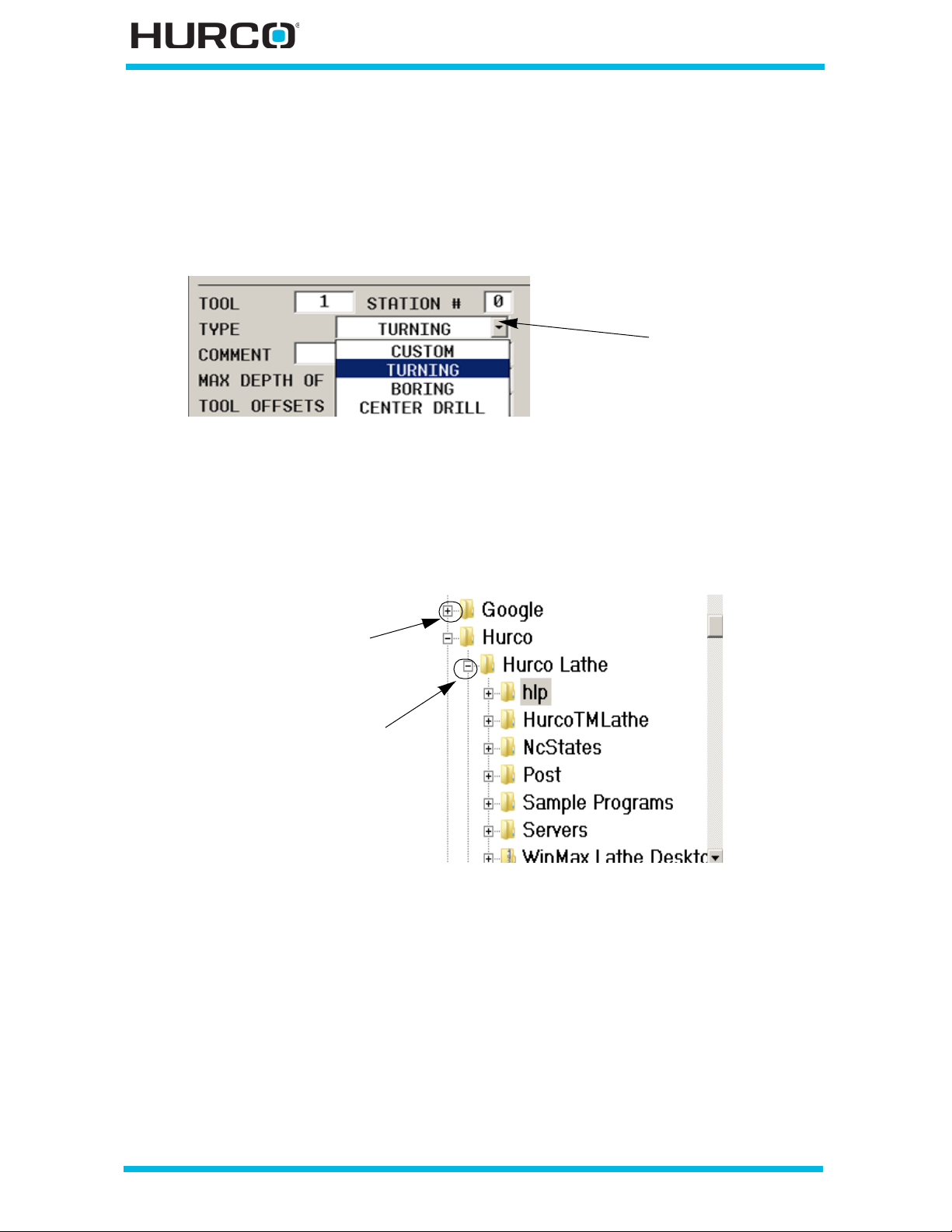
• On the keyb oar d (if us in g), press the co rre spo nding func tio n key ( F1 , F2, F3 ,
Select the small
arrow to view a
drop-down list; use
arro w keys to
hig hlight cho ice
and Enter console
button to select
Sele ct the “+” to expan d
and view the files and
Select the “-” to collapse
folders in a folder
(close) and hide the
files and folders in a
folder
etc).
Drop-down Lists
Many fields contain a choice of items that are viewed by pulling down a list:
Figure 1–4. Example of a drop-down list
Expand and Collapse Files
In the Program Manager, files can be expanded or collapsed as follows:
1 - 8 Machine and Console Basics v546GS Getting Started—WinMax Lathe Max Control
Figure 1–5. Example of Expand and Collapse Files
Page 23
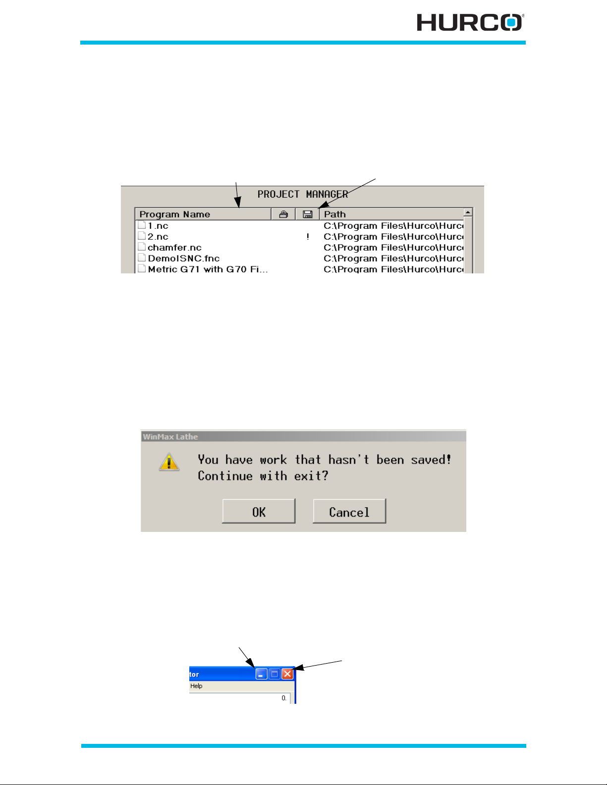
Sorting and Resizing Columns
Select to sort column
Select and drag to resize column
Minimize
Close
On some screens that contain columns, data in a column can be sorted ascending to
descending or descending to ascending by selecting the column heading. Columns can be
resized by dragging the column divider in the header.
Figure 1–6. Example of Sorting and Resizing Columns
Pop-up Messages
During machine operation and programming, pop-up boxes may be displayed to convey
prompts or status messages. These pop-up boxes can be closed by selecting the
appropriate button (i.e., YES or NO or OK). Some pop-up boxes may only provide
informational messages and will be displayed for a few seconds before they automatically
close.
Figure 1–7. Pop-up message example
Certain pop-ups, such as the calculator, can be minimized by selecting the “—” in the
upper right co rner. Thes e pop-ups will remai n o pen but ar e “hidden” i n the status bar, and
can be viewed again by select ing the status bar button. These pop-ups can also be closed
by selecting the “X” in the upper right corner:
Figure 1–8. Pop-up showing minimize and close icons
Getting Started—WinMax Lathe Max Control v546GS Machine and Console Basics 1-9
Page 24
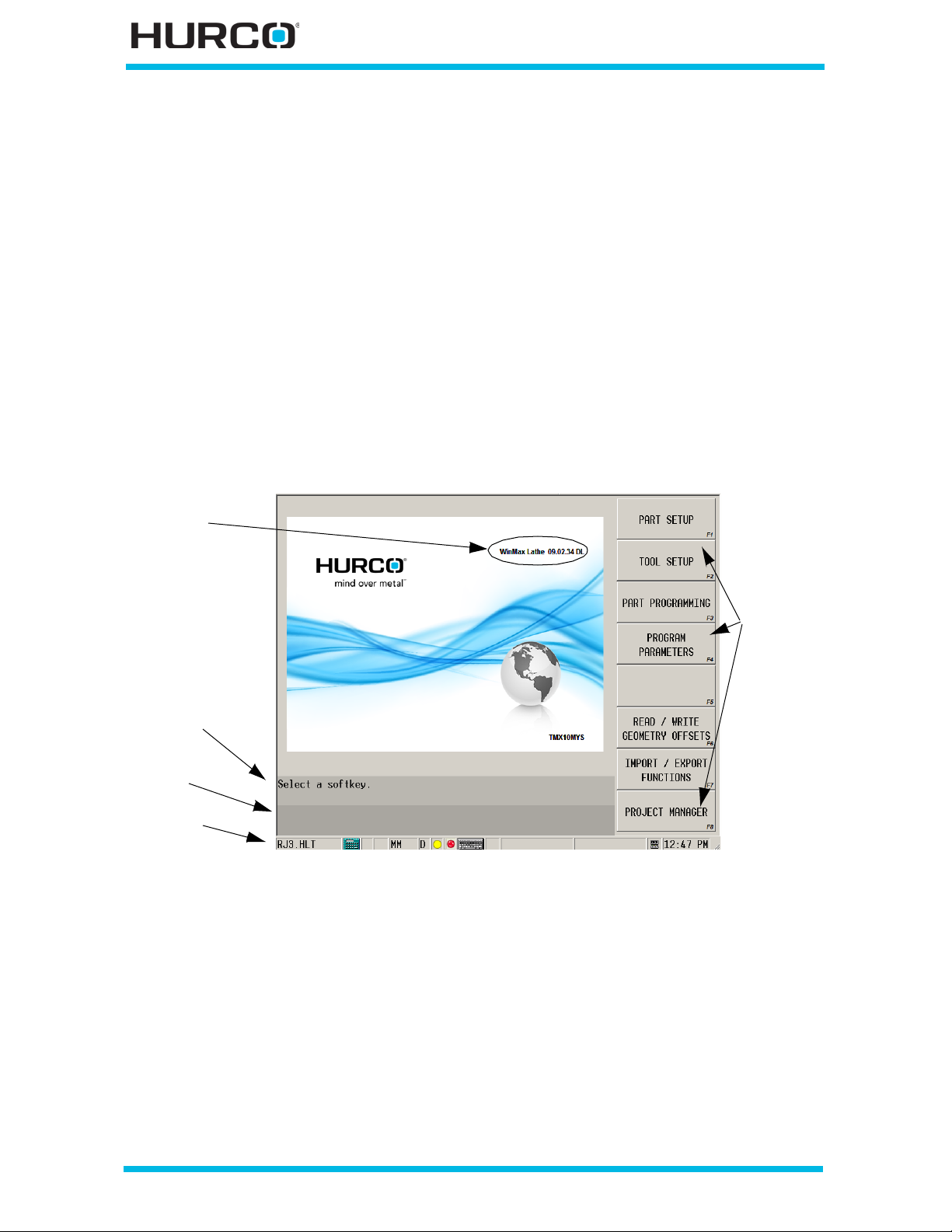
Status Bar
Softkeys
Error/Status
Prompts
WinMax Version
area
Status Bar
The Status Bar appears at the bottom of every WinMax screen. It displays the program
name of the current active part program, a calculator icon, the current unit of measure
(inch or mm), the keyboard icon, and the current time. When viewed on a Max console,
all icons appear in the same status bar; when viewed on a dual-screen console, the
program name and calculator icon appear on the left screen status bar, and the unit of
measure, keyboard icon and time appear on the right screen status bar.
• Calculator—To use the calculator function, select the calculator icon.
• Keyboard—To use the on-screen keyboard, select the keyboard icon.
• Unit of Measure—To chan ge th e un it of meas ur e, sel ect the un it o f me asur e
(Inch or Metric). The unit of measure can be toggled and affects data block
and tool setup screens.
• Programming Mode—To change the programming mode, select the R
(Ra d iu s) o r D ( D iam e ter) . T he p ro gr a mm in g m ode c an b e to gg led a nd af fe cts
data block and tool setup screens.
Figure 1–9. Status Bar and other areas
1 - 10 Machine and Console Basics v546GS Getting Started—WinMax Lathe Max Control
Page 25
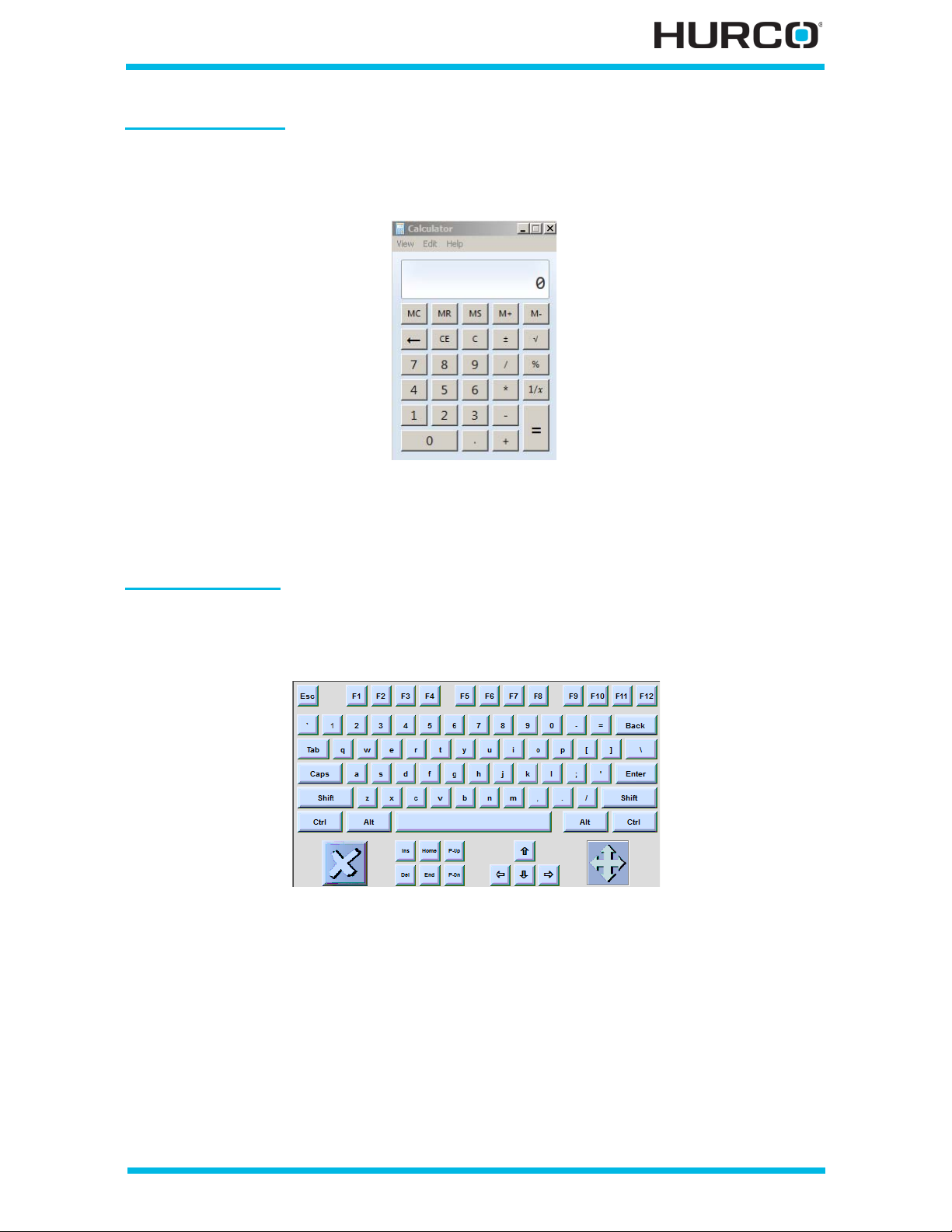
Pop-up Calculator
Select the calculator icon in the Status Bar to open the calculator. The calculator appears
on screen and is operated using a pointing device to select the calculator keys on screen.
Figure 1–10. Pop-up Calculator
When the calculator is minimized (with “—” in the upper right), the last calculation is
retained, but when it is closed (with “X” in the upper right), the last calculation is erased.
Pop-up Keyboard
Enter part program names using the on-screen, pop-up keyboard. The pop-up keyboard
is a vailable for entering text, such as naming a part program.
Figure 1–11. Pop-up Keyboard
1. Either se lect the keyboard icon located in the screen’s status bar or
simultaneously press the Alt and Input keys on the console to ac tivate the
keyboard.
2. Use a pointing device such as the stylus to select char acters from the
keyboard.
3. Press the Enter key to update a field and advance the cursor af ter the
characters are selected in the text field (e.g., after creating a program name).
4. Select the X located in the lower left corner of the text entry window to close
the keyb oard.
Getting Started—WinMax Lathe Max Control v546GS Machine and Console Basics 1-11
Page 26

On-screen Help
On-scr een Help provides information about using WinMax. The Help is context-sensitive
to the screen level. Press the consol e Help button to displa y the Help topic for the current
screen. The following list describes Help functions:
• Buttons in the upper left-hand corner of the Help screen are used to move
throu g h Help topics and print screens.
•Use the Hide button to hide the navigation pane.
•Use the Back button to return to the previous Help screen.
•Use the Print button to print the current displayed Help topic, if a printer
is attached and configured. See Acces s ing t he Wi nMax Help in PDF f orm at
for printing, on page 1 - 13 for more information about printing.
• Use the arrow buttons to move between pages within a Help to pic and to
move through topics.
•Use the Contents tab for a list of information sorted by subject:
1. Select the “+” to expand the topic and view sub-topics.
2. Select the topic to display it.
•Use the Index tab to show the Help index:
1. Qui ckly scroll to an index topic by typing the topic in the box at the top of
the index.
2. Select a topic and the Display button to view the topic.
•Use the Search tab to search the Help for a word or phrase:
1. Type the s earch word(s) into the text box at the top of the p ane.
2. Select the List Topics button. A list of topics that contain the search
word(s) is displayed.
3. Select a topic and the Display button to view that topic.
•Use the Favorites tab to save Help topics for quick access:
1. Select the Add button at the bott om of the pane to add the current topic.
2. Select a topic from the Favorites list, and select the Display button to view
it.
3. Select a topic from the Favorites l ist, and select the Remove button to
remove it from the list.
1 - 12 Machine and Console Basics v546GS Getting Started—WinMax Lathe Max Control
Page 27

Accessing the WinMax Help in PDF format for printing
The WinMax On-screen Help is also provided in PDF format for easy printing. The
information contained in the PDF files is identical to the on-screen Help. The PDF files
may be copied to a USB memo ry device to be transferred to a PC for viewing or printing.
Here are the steps to access the PDF files:
1. From the Input screen, select the PROGRAM MANAGER F8 softkey.
2. Select the DISK OPERATIONS F7 softkey.
3. In the left-hand pane, navigate through the folders:
• For WinMax Lathe on a machine, the path is
D:\Hurco\Hurco Lathe\hlp.
• For WinMax Lathe Desktop on a PC, the path is
C:\Program Files\Hurco\Hurco Lathe\hlp.
The PDF files will appear in the right-hand pane.
The SHOW ALL FILE TYPES field in User Inte rface Settings mus t be
set to YES (default is NO) in order to see the PDF files in the
directory. Access the SHOW ALL FILE TY PES field in Auxiliary Mode,
Utilities/ User Preferences/ User Interface Settings.
4. Highlight the PDF file(s) in the rig ht-hand pane, and select the COPY F2
softkey.
5. Ensure that your media is loaded (a US B memory device in the USB port), and
navigate to the proper location in the left-hand pane of the DISK OPERATIONS
screen (USB port E:). Highlight the desired location.
6. Place the cursor in the right-hand pane and select the PASTE F3 softkey to
paste the PDF file(s) to the desired location.
7. You may now remove your media and load the PDF file(s) onto a PC for
viewing and printing.
Getting Started—WinMax Lathe Max Control v546GS Machine and Console Basics 1-13
Page 28
Control Panel Function Groups
1
2
5
3
4
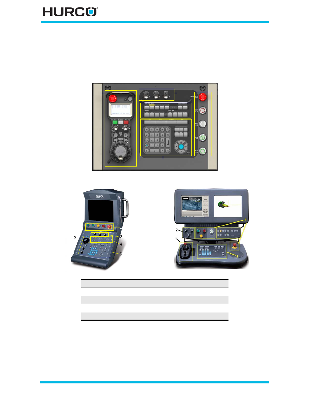
The butt ons, keys, and dials on the console are grouped by their functions. Here are the
control panel groups on a WinMax Lathe Max console:
1. Machine Control buttons
2. Axis and Spindle Control dials
3. Jog Control functions
4. Machine Operations keyboard
5. Programming keyboard
Figure 1–12. Control Panel Groups
Mach ine Control
Machine Control buttons start and stop machine operation as follows:
• Emergency Stop Button—There is an Emergency Stop button located on
1 - 14 Machine and Console Basics v546GS Getting Started—WinMax Lathe Max Control
Page 29
the console. Press the Emergency Stop button to stop all motion and remove
power from all electrical circuits. The red beacon flashes above the control.
This button locks down when pressed. To release it, twist the button in the
direction indicated by the arrows.
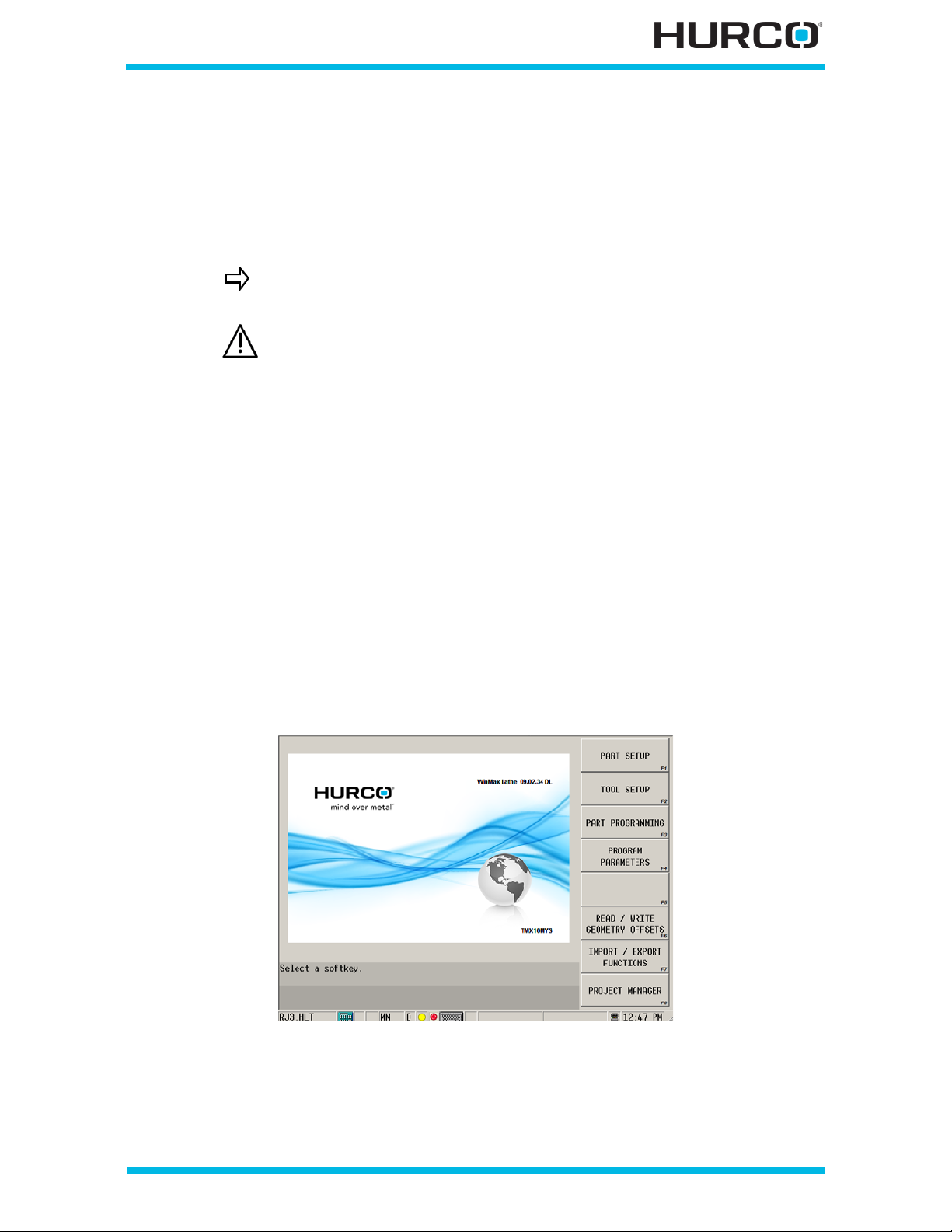
An Emergency Stop icon appears in the status bar at the bottom of the
screen to show the Emergency Stop button has been pressed.
Learn the location of all Emergen cy Stop buttons on the turning
center before operating.
If the Eme rg ency S t op butto n is pressed during execution of a part
program, the tool should be jogged c lear of the part before resuming
operation.
• Power On—enables the relay control system. This button must be
illumin ated to operate th e machine, but may be switched off while creat ing or
editing a part program.
• Start Cycle —activates machine operation. When the machine is in an act ive
mode, the Start Cycle flashes to indicate the machine is ready. When this
button is pressed, the light s witches off or may stay on for the d uration of the
selected operation, depending on the operation.
• Stop Cycle—st ops axes movement, then stops the spindle. The button lights
an d remains illuminated until another mode key is pressed.
• Feed Hold —stops all axes movement when the tool is in the programmed
feedra te region, except a tap operation where motion is sto pped when th e tap
is complete. Pressing the button a second time allows m achine positioning to
resume. The spindle is on and remains on. A yellow icon appears in the status
bar at the bottom of the screen when the Feed Hold button is pressed, and
the yellow beacon flashes above the control.
Figure 1–13. Input screen with Feed Hold and Emergency Stop icons
Getting Started—WinMax Lathe Max Control v546GS Machine and Console Basics 1-15
Page 30

Axis and Spindle Control
The override knobs are used to control machine movement and adjust the spindle and
axes. The knobs on the upper console allow you to override the programmed axis
feedrate, spindle speed settings, and the rapid traverse feedrat e.
• Axis F eed R ate—controls the programmed axis feedrate while running a
program. Turning the dial counterclockwise slows the feedrate; turning the
dial clock wise increases the feedrate.
• Select Min to slo w the feedrate to 0% of the programmed value.
• Select Max to increase the feedrate to 150% of the programmed value.
• Select the 12:00 position (dial indicator straight up) to control the
feedrate at its programmed value.
• Rapid Override—overrides the programmed rapid traverse feedrate. The
turret will move at rapid traverse feedrate during position moves or nonturnin g motion. Turn ing the dial counterc lockwise sl ows the feedrat e; turnin g
the dial clockwise increases the feedrate.
• Select Min to slo w the rapid feedrate to 0% of the programmed value.
• Select Max to increase the rapid fe edrate to 100% of the programmed
value.
On TMX, TMX MY, and TMX MYS machines the Rapid Override also
affects the indexing speed of the turret; however, the Maximum
Rapid rate set in Program Parameters does not affect the indexing
speed of the turret.
When the Rapid Override is set at 0% the turret will stil l move as the
override minimum for the turret indexing speed is 1%.
TMX machines
• Rapid Override at 100% - Turret rotates at approximately 42
RPM (Maximum Speed).
• Rapid Override at 1% - Turr et rotates at approximately 0.42 RPM
(Minimum Speed).
TMX MY and TMX MYS machines
• Rapid Override at 100% - Turret rotates at approximately 83
RPM (Maximum Speed).
• Rapid Override at 1% - Turr et rotates at approximately 0.83 RPM
(Minimum Speed).
1 - 16 Machine and Console Basics v546GS Getting Started—WinMax Lathe Max Control
Page 31

• Spind le Speed—controls the spindle speed. Turning the dial
counterclockwise slows the spindle; turning the dial clockwise increases
spin dl e spee d .
• Select Min to slow spindle speed to 0 RPM.
• Select Max to i ncrease spindle speed to 200% of the programmed spindle
speed.
The spindle reacts differently depending upon the Speed and Feed
settings in the Too l Setup. Refer to Turnin g Tool Setup Fields, on
page 4 - 20 for information about programming Speed and Feed.
• If your spindle is set to IPM mode in Tool Setup, axis feedrate is
unaffected by spindle speed override.
• If your spindle is set to FPR mode in T ool Setup, the ax is feedr ate
adjusts as the spindle speed is adjusted.
Two-Axis (TM series) and Two-Axis Programmable Tailstock (TMX
series) turning centers have one Spind le Speed knob.
Live-Tooling (TMM series) and Live-Tooling and Y-Axi s Motion (TMX
MY series) turning centers have two Spindle Speed knobs:
• S pindle 1 Speed—controls the Main spindle.
• S pindle 2 Speed—controls th e Live Tooling spindle.
Live-Tooling, Y-Axis Motion, and Sub-spindle (TMX MYS) turning
centers have t hree Spindle Speed knobs:
• S1—S3 Speed (concentric override knob)—the larger bottom
knob controls the Main spindle; the smaller top knob controls the
Sub sp indle.
• S 2 Speed—controls the Live Tooling spindle.
Getting Started—WinMax Lathe Max Control v546GS Machine and Console Basics 1-17
Page 32
Mach ine Operati ons
The Machine Operations console keys are used to run part programs and control the
machine during cutting. These keys are labeled under the Machine Mode, Coolant,
Spindle, and Turret groupings. An LED lights next to a selected key to indicate a mode is
selected. Refer to Machine Operation Basics, on page 5 - 1 for detail s about op erating the
machine.
Machine Mode
The Machine Mode console keys have these functions:
• Auto—allows you to run a part program automatically in Auto mode. Please
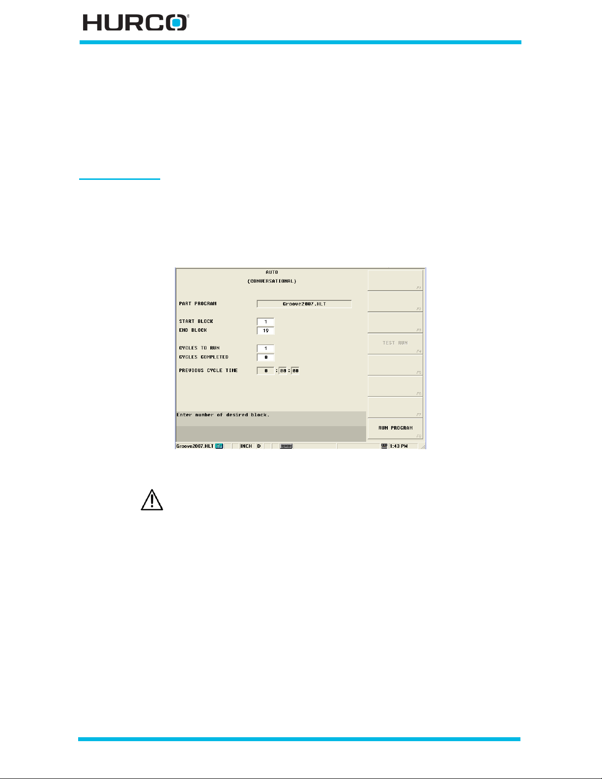
refer to Auto Mode Operation, on page 5 - 52 for details. Here is an Auto
(Conversational) screen:
Figure 1–14. Auto (Conversational) screen
During execution of the part program in Auto or Single mode, you
can switch between Auto and Single mode by pressing the
corres pond i ng c ons ole k e y. You ca n al s o sel ect t he Interrupt or Opt
Stop keys at any time during execution of a part program in Auto or
Single mode.
• Interrupt—halts machine operation, stopping the axis feed, spindle speed,
and coolant during automatic execution of a program to allow ma nual
functions, such as cleaning the workpiece. Press Auto to resume the part
program.
• Single—allows you to run a part program automatically, but the machine
stops the axes after each data block. Press the Start Cycle button, and the
program runs, but the machine stops the axes at the end of each NC motion
or actio n that is generated for the Conversational block.The s pindle will
continue running at the last programmed speed. Press the flashing Start
Cycle button to resume the automatic machining operation and execute the
next block.
1 - 18 Machine and Console Basics v546GS Getting Started—WinMax Lathe Max Control
Page 33
Examine the part program to determine the precise tool movement
to avoid interference before executing a Single Cycle operation.
• Opt Stop—stops the machine when this button is selected and there is a
programmed Position block with Option Stop e nabled. Machine operation
resumes when you press the flashing Start Cycle button. If Opt Stop is not
on, the Program will not stop at the Option Stop block.
• Manual—provid es access to manual m achine operations suc h as i ndexing the
turret, setting Home for each axis, performing diagnostics, accessing
accessories or options, performing chuck operations, turning on or off the
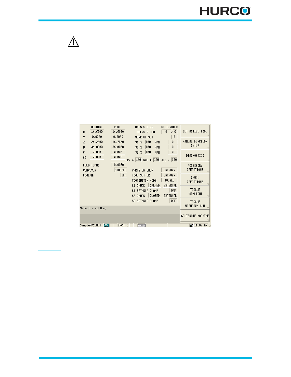
worklight and washdown gun, and calibrating the machine. The Manual
screen information for axes and spindles depends upon the machine
configuration. Refer to Manual Mode Operation, on page 5 - 7 for details.
Figure 1–15. Manual screen (TMXMYS machine configuration shown)
Coolant
• Auto—enables the coolant to be automatically controlled On and Off while
running a program in Auto Run mode, depending on the Coolant setting in
Tool Setup for each tool used in a program. The Coolant LED is On in Auto
mode or when using the optional Verification Graphics when the Coolant is
programmed to be On.
When enabled, the Coolant starts whenever the tool is selected in a data
block. The coolant turns off at the end of the program or when a tool is
selected that does not have Cool ant On set. This key cannot be activated in
Manual mode. In Auto mode, Coolant is automatically enabled. Pressing this
key disables automatic coolant operation. Press Auto to enable Auto coolant
control.
• Primary—functions only on machines equipped with a primary (i.e., flood)
coolan t system. Activate s the primary coolant system when the machine is in
Auto or Manual mode, and overrides a Coolant Auto operation. Pressing the
Primary key a second time turns off this operatio n.
Getting Started—WinMax Lathe Max Control v546GS Machine and Console Basics 1-19
Page 34

• Secondary—this fea ture is not current ly available.
Spindle
These Spindle console keys are available for two-axis (TM and TMX series) machines:
• On—activates the spindle if the machine is in manual mode. The Spindle LED
is On in Auto or Single mode. The Start Cycle button must also be pushed to
start spindle rotation.
• Off—stop s spindle rotation during manual operation if the Spindle On button
was previously pressed. You can also use the Off key with the Feed Hold
butt on to abort a program.
In addition to pressing the Off console key, any of these methods
stop spindle r otation f or two-axis (T M series) machines:
•Press the Stop Cycle button.
•Press the Manual consol e key.
• Depress the Emergency Stop button.
These Spindle console keys are available for live-tooling (TMM and TMX MY series)
machines:
• S1—activates Spindle 1 (M ain spindle) wh en pressed. The LED lights to v erify
Spindle 1 is active.
• S2—activates Spindle 2 (Live-tooling spindle) when pressed. The LED lights
to verify Spindle 2 is active.
Use any of these methods stop either active spindle’s rotation for
live-tooling (TMM series) machines:
•Press the S1 c onsole key when Spindle 1 is active.
•Press the S2 c onsole key when Spindle 2 is active.
•Press the Stop Cycle button.
•Press the Manual consol e key.
• Depress the Emergency Stop button.
The spindle must be stopped before the C axis is active for jogging
using the x1, x10, or x100 console jog handwheel multiplier keys.
If you select a spindle for jogging then select to jog the C Axis, the
spindle automatically stops.
1 - 20 Machine and Console Basics v546GS Getting Started—WinMax Lathe Max Control
Page 35

These Spindle console keys are available for TMX MYS series machines:
• S1—activates Spindle 1 (Main spindle) when pressed. The LED lights to verify
Spindle 1 is active.
• S2—activates Spindle 2 (Live-tooling spindle) when pressed. The LED lights
to verify Spindle 2 is active.
• S3—activates Spindle 3 (Sub-spin dle) when pressed. The LE D lights to verify
Spindle 3 is active.
• S-Synch—synchronizes Spindle 1 and Spindle 3 for on-the-fly part transfer.
The LED lights to verify S-Synch is active.
Use any of these methods stop any active spindle rotation:
•Press the S1 c onsole key when Spindle 1 is active.
•Press the S2 c onsole key when Spindle 2 is active.
•Press the S3 c onsole key when Spindle 3 is active.
•Press the S-Synch button when S-Synch is active.
•Press the Stop Cycle button.
•Press the Manual consol e key.
• Depress the Emergency Stop button.
The spindle must be stopped before the C axis is active for jogging
using the x1, x10, or x100 console jog handwheel multiplier keys.
If you select a spindle for jogging then select to jog the C Axis, the
spindle automatically stops.
Turret
The Turret console keys are active only in Manual mode. The Turret LED is On during a
tool change or if using the optional Verification Graphics when a tool change would occur.
• - (Minus)—Decre ments the tool s tation once for each key press. For ex ample,
pressing the Turret minus key once changes the Active Tool from Tool 4 to
Tool 3.
• + (Plus)—Increments the tool station once for each key press. For example,
pressing the Turret plus key once changes the Active Tool from Tool 4 to Tool
5.
The Start Cycle button flashes when the Turret -/+ console key is
pressed. Press the flashing button to manually move the turret.
Getting Started—WinMax Lathe Max Control v546GS Machine and Console Basics 1-21
Page 36

Jog Units
A jog unit is use d to manual ly jo g the ax es and contr o l machi ne op er atio n. H and-h eld , or
remote, jog units can be removed from the console and carried closer to the work piece.
Max5 Remote Jog Units
Max5 console offers a choice of remote jog units:
• Basic—portable hand-held unit with axes and machine operation controls.
• Premium—portable hand-held jog unit with all the features of the Standard
jog unit, plus an LCD touchscreen that disp lays axes position in Manual
mode, Part Setup, Tool Setup, Work Offsets, and Aux Work Offsets.
• Wireless—the Premium jog unit without wired connection.
Max4 Remote Jog Unit
The Console Jog Unit is standard on the Max4 console.
The hand-held remote Max4 Jog Unit is an option on the Max4 console.
Jog Unit Operation
Basic operation of a jog unit is as follows:
1. Select an axis with the Axis Select Switch.
2. Use the Jog Feed Keys:
a. Select either the + or – J og Feed Keys.
b. Adjust Jog Feed Override to override the p rogrammed axis feedrate.
OR
3. Use the Hand Wheel Multiplier:
a. Select a hand wheel resolution with one of the Hand Wheel Multiplier Keys.
b. Rotate the Jog Hand Wheel.
Other than the Emergency Stop button, the Jog Unit does not affect
running programs.
The Wireless Remote Jog Unit must be paired with the machine
before first use. See Wireless Jog Unit Pairing, on page 1 - 54.
1 - 22 Machine and Console Basics v546GS Getting Started—WinMax Lathe Max Control
Page 37

Setting Jog U nit Parameters
To access the parameters :
1. Press the Manual Mode console key to display the Manual screen.
2. Press the Manual Function (F2) softkey. The Jog Unit parameters are
displayed:
• Manual Jog Feed— enter the desired manual jog axis feedrate. The
range is f rom 0.0 to the machine’s maximum feedrate.
An axis may have a maximum jog feedrate slower than other axes. This
slower axis can only move at its maximum jog feedrate (and not the
higher f eedrate of other axes).
For example, the X and Y axes on a machine each have a maximum jog
feedrate o f 787 inches per minute (ipm). The Z axis has a maximum jog
feedrate of 100 ipm. Without using the jog feedrate override, the X and Y
axes can jog at 787 ipm, but the Z axis is limited at 100 ipm.
• Manual Spindle Speed —enter the spindle speed when the Spindle On
console key is pressed. This value can not be greater than the machine’s
maximum spindle speed. Entering a negative value (e.g., -500) causes
the spindle to reverse (turn counterclockwise) at that speed.
• Rotary J og Feed (for machines with rotary or swivel axes)—enter the
jog feedrate in RPM.
Getting Started—WinMax Lathe Max Control v546GS Machine and Console Basics 1-23
Page 38
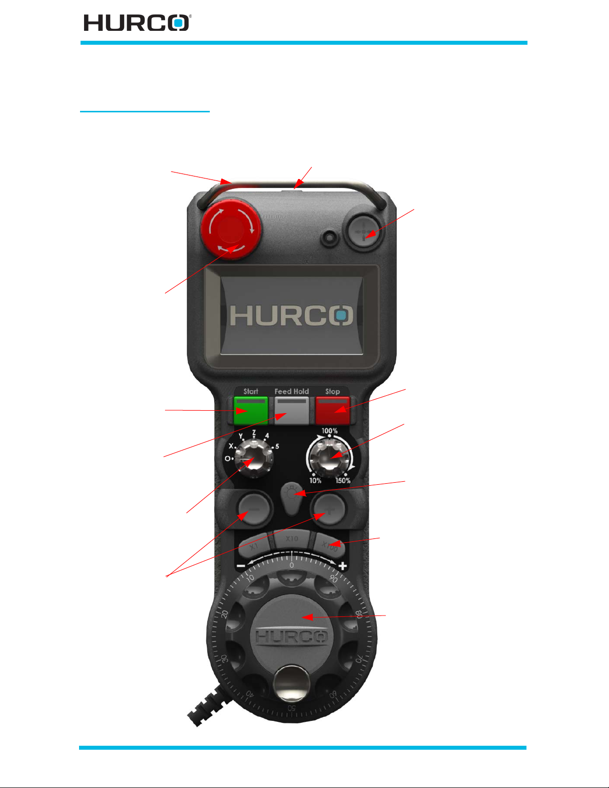
Max5 Remote Jog Units
Store Position
Jog Handwheel
Rapid Jog Rate Knob
Flashlight On/Off
Handwheel Multipliers
Stop Cycle
Feed Hold
Start Cycle
Jog Feed
Flashlight
Emergency Stop
Handle
Axis Select Knob
Ba sic Re m o te Jog Un i t
Pictured belows is the Basic Unit. See Remote Jog Units, on page 1 - 28 for more details.
1 - 24 Machine and Console Basics v546GS Getting Started—WinMax Lathe Max Control
Page 39
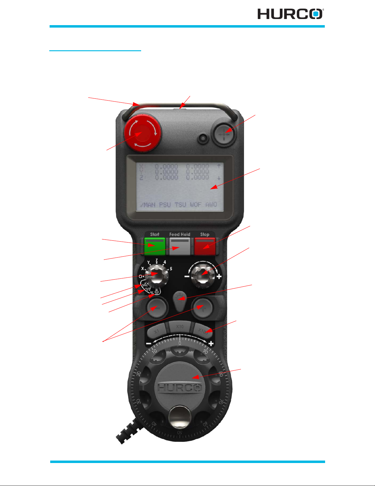
Prem iu m Remote Jog Un it
Store Position
Flashlight
LCD Touchscreen
Jog Handwheel
Rapid Jog Rate Knob
Flashlight On/Off
Handwheel Multipliers
Stop Cycle
(Premium and
Wireless)
Start Cycle
Jog Feed
Emergency Stop
Handle
Feed Hold
Axis Select &
Override Knob
spindle
rapid
feed
Pictured below is the Max5 Premium Remote Jog. See Remote Jog Units, o n page 1 - 28
for more information.
Getting Started—WinMax Lathe Max Control v546GS Machine and Console Basics 1-25
Page 40
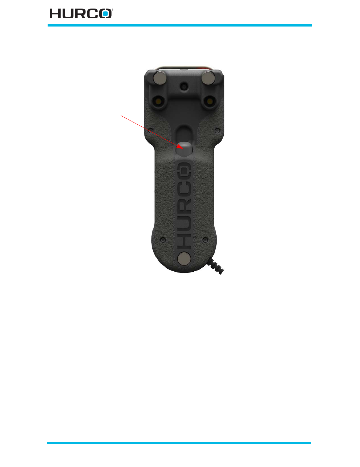
This is the view of the back of the Max5 Remote Jog Unit (both Basic and Premium):
Enable button
1 - 26 Machine and Console Basics v546GS Getting Started—WinMax Lathe Max Control
Page 41
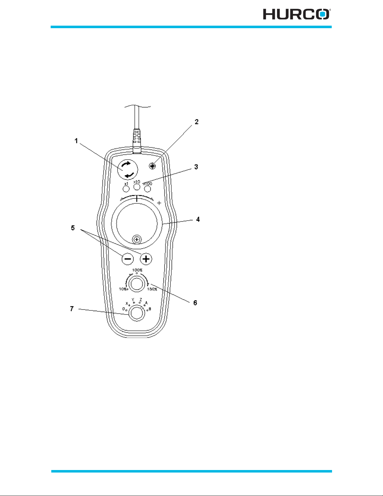
Max4 Remote Jog U nit
1. Emergency Stop Button
2. S tore P osition K ey
3. Han d Whee l M u ltiplier Keys
4. J og Han d Wheel
5. Jog F eed K eys
6. Jog Feed Overri de
7. Axis Select Swi tch
Getting Started—WinMax Lathe Max Control v546GS Machine and Console Basics 1-27
Page 42

Remote Jog Units
• Emerge ncy Stop— stops all spindle and table motion.
• Store Pos ition—records the current axis position in the part program’s
setup screens.
• LCD sc reen (available on ly on Premium units)—displays Manual mode
(MAN), Part Setup (PSU), Tool Setup (TSU), Work Offsets (WO), and Aux
Work Offsets (AWO).
Mode Selections appear at the bottom of the LCD screen. Use the
touchscreen to select a mode; a check mark appears by the current selection.
Scroll up, down, left, and right, and select items using the touchscreen.
• MAN—manual mode. The display s hows machine or part positions for X,
Y, and Z. Positions are zone relative on dual-zone machines.
• PSU—Part Setup. The display shows current part setup information.
• TSU—Tool Setup. The display shows current tool setup information. The
initial tool displayed is the current tool in spindle.
• WO—Work Off sets. The display shows G54, G55, G56, G57, G58, G59
and Shift values.
• AWO—Aux Work Offsets. The display shows offsets 1-93.
• Start Cycle (Max5)—activates machine operation. The Start Cycle button on
the Remote Jog Unit must be used in conjunction with the Enable button,
located on the back of the jog unit. P ress and hold the Enable button and
press the Start Cycle button on the jog unit. The Enable button can be
released after the cycle is started.
Both the Enable button and the Start Cycle button must be held
down to run the spindle with the enclosure doors open.
• Feed Hold (Max5)—stops all axes movement (except a tap operation) when
the tool is in the programmed feedrate region. Pressing the button a second
time allows machine positioning to resume.
• Stop Cycle (Max5)—stops axes movement, then stops the spindle.
• Axis Selector (& O verride ) Knob – selects the axis to jog. On Premium
unit only, this knob also control the override mode: feed, rapid, or spindle.
Indicator appears on screen for selected axis. Axis selections are O, X, Z, C1,
S1, W, Y, C3, and S3 depending on the configuration.
See Setting Jog Unit Parameters, on page 1 - 23 for instructions on
setting the Jog Unit parameters.
1 - 28 Machine and Console Basics v546GS Getting Started—WinMax Lathe Max Control
Page 43

• 0 disables jogging. Any illuminated multiplier key LEDs are shut
off and have to be reselected before jogging again.
• X is for jogging the x axis.
• Z is for jogging the Z axis.
• C1 is for jogging live-tooling axis.
• C3 is for jogging sub-spindle live-tooling axis.
• S1 is for jogging the Main spindle. This selection is useful for
heavy parts because you can turn the spindle with the spindle
motor to check to be sure the part does not wobble. You can also
use this selection to check the part’s alignment when clamped in
the optional chuck or when using the optional tails tock to suppor t
the part.
• S3 is for jogging the Sub spindle on TM X MYS machines.
• W is for jogging the programmable tailstock on TMX MY
machines.
• Y is for jogging the Y axis motion on TMX MY and TMX MYS
machines.
• Flashlight (Max5)—toggle flashlight or machine work light on and o ff with
this button. A short duration press toggles the flashlight. Flashlight
illuminates from the top of the remote jog unit. A longer duration press
toggles the machine work light.
• Rapid Jog Rate Knob (Max5)—controls the rapid jog rate when an axis is
selected on the Axis Selector (& Override) Knob. On Premium model, when
the Axis Selector & Override Knob is set to override mode (one of the bottom
three positions), the Rapid Jog Rate Knob controls the override (feed, rapid,
or spindle).
• Jog Feed Override (Max4)—control the jog speed (10% to 150%) of the
nominal value. Jog % is displayed on the screen.
• Jog Feed Keys —select minus (-) or plus (+) jog direction.
• Jog Handwheel —select minus (-) or plus (+) jog direction.
• Handwheel Multiplier Keys - defines the hand wheel resolution.
• x1 - defines a one-to-one ratio (each click eq uals .0001 inch, or .00254
mm).
• x10 - defines a 10-to-one ratio (each click equals .001 inch, or .0254
mm).
• x100 - defines a 100-to-one ratio (each click equal s 0.01 inch, or .254
mm. One full turn equals 1 inch, or 25.4 mm).
• Enable button—on machines with CE enabled, must be held to use the Start
Cycle bu tton and the +/- jog on the unit.
Getting Started—WinMax Lathe Max Control v546GS Machine and Console Basics 1-29
Page 44

Enable Button
The Max5 Rem ote Jog, Max4 Remot e Jog, single-s creen and dual -screen c onsoles may b e
equipped with an Enable button. The Enable button is functional only on machines that
have CE enabled.
The Enable button has three positions: fully up (off), middle (on), and fu lly down (off).
The button must be in the middle position to be enabled. The Enable button is required
for the following operations:
• Start Cycle (on Max5 Remote Jog only)—press and hold the Enable button
and press the Start Cycle button on the unit. The Enable button can be
released after the cycle is started.
Both the Enable button and the Start Cycle button must be held
down to run the spindle with the enclosure doors open.
It is not necessary to use the Enable button when using the Start Cycle
button on the console.
• +/- Jog—press and hold the Enable button while simultaneously selecting
eithe r “+” or “-” button to jog the selected axis, only when the enclosure
doors are open. If the enclosure doors are closed, it is not necessary to use
the Enable button to jog the axes.
It is not necessary to press and hold the Enable button to jog the axis using
the hand wheel at x1, x10, or x100 speeds.
1 - 30 Machine and Console Basics v546GS Getting Started—WinMax Lathe Max Control
Page 45
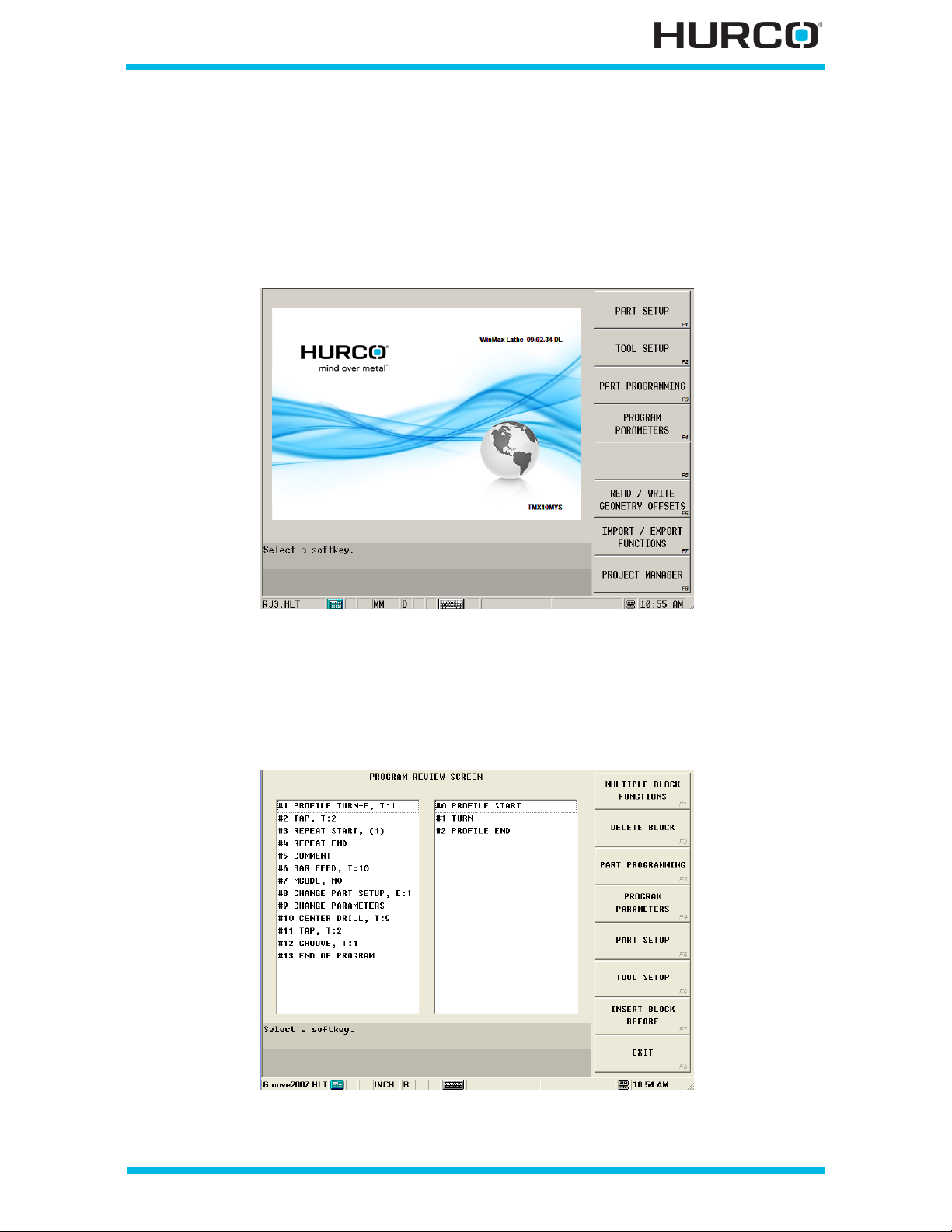
Pr og ram ming Key bo ar d
Programming Mode console keys are named for the screens they activate:
• Input—displays the main programming screen used to c reate and edit part
programs. From this screen, access Part Setup, Tool Setu p, Part
Programming, Programming Parameters, and Project Manager menus.
Figure 1–16. Input Screen
• Review—for Conversational programs, prov ides an ou tline view of the blocks
currently programmed, including type of block and tool used. Th e left-hand
pane lists all of the program blocks. The r ight-hand pane lists the elements
for the selected Profile data block. Jump to a desired block by selecting the
block and pressing Enter.
Figure 1–17. Program Review screen—Conversational Part Programming
Getting Started—WinMax Lathe Max Control v546GS Machine and Console Basics 1-31
Page 46
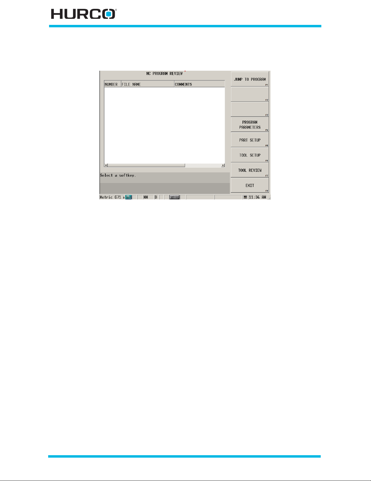
For Nume rical Control (NC) programs, the Review key displays the NC
subroutines by number.
Figure 1–18. Program Review screen—NC Programming
1 - 32 Machine and Console Basics v546GS Getting Started—WinMax Lathe Max Control
Page 47
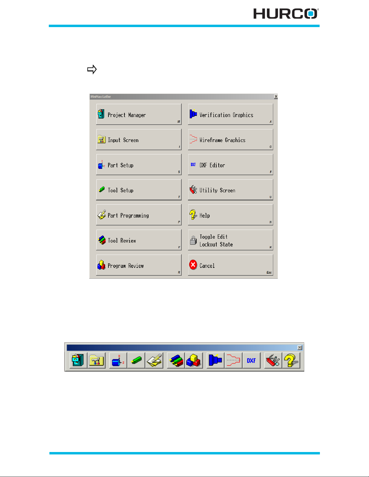
• Aux/Menu—displays a pop-up menu for accessing functions for developing
and managing programs.
If using the WinMax Lathe Desktop softw are, select the F9 key to
access this screen.
Figure 1–19. Menu Console Key’s Pop-up selections
A menu toolbar is also available by selecting anywhere on the status bar at
the bottom of the screen. This toolbar provides access to the same functions
as the pop-up menu. To close the toolbar, select the X in the upper right
corner of the toolbar. The toolbar is standard with WinMax Lathe Desktop.
Figure 1–20. Menu Toolbar
• Help—displays on-screen help text. Place the cursor on a screen and press
the Help console key for information about the screen. Refer to On-screen
Help, on page 1 - 12 for more information.
Getting Started—WinMax Lathe Max Control v546GS Machine and Console Basics 1-33
Page 48

Stand ard Keys
These keys function as they would on a standard AT-keyboard. They perform functions
related to the programming mode: Tool Review, Program Review, and the NC editor
mode.
• Insert —allows you to:
• insert a tool at the current cursor location in the Tool Review screen.
• insert a conversational data block at the current cursor location in the
Program Review screen.
• toggle the NC edi tor mode between Insert and Overwrite.
• Delete—allows you to:
• delete a tool at the current cursor location in the Tool Review screen.
• delete a conversational data block at the current c ursor location in the
Program Review screen.
• delete a character to the right of the cursor for convers ational programs.
• delete all characters in a highlighted field.
• delete a character at the current cursor location on the NC Editor screen.
• Home—positions the cursor:
• at the first tool listed when in the Tool Review screen.
• at the first data block listed when in the Program Review screen.
• in the Block field for the first data block when in a data block other than a
Profile.
• in the Element field when in a Profile data block.
• at the beginning of the line when in the NC Editor screen.
• End—positions the cursor:
• at the last tool listed when in the Tool Review screen.
• at the last d ata block listed when in the Program Review screen.
• at the End of Program data block when in a data block other than a
Profile.
• at the New Profile Element data block when in the Element field in a
Profile.
• at the end of the line when in the NC Editor sc reen.
• Page Up—allows you to:
• position the cursor at the beginning of the previous page or move
backward in the conversational part program, depending on the type of
screen
• jump to the first visible line in the program on the NC Editor screen.
• Page Down—allows you to:
• position the cursor at the beginning of the next page or mo ve forward in
the conversational part program, depending on the type of screen
• jump to the last visible line in the program on the NC Editor screen.
1 - 34 Machine and Console Basics v546GS Getting Started—WinMax Lathe Max Control
Page 49

Cursor Control Keys
These keys control cursor movement and perform programming operations:
• Arrow keys—up and down arrows move the cursor from one field to the
next; left and right arrows cycle through all selections of a menu selection,
moves through elements of a profile, or moves the cursor within a numeric
field.
• Enter key (↵)—accepts the information typed in a text field or moves to the
next field.
Sp ecia l Function Key s
These keys provide additional functionality to many other keys. For example:
• alt (alternate) console key
alt + Input Dis play the Pop- u p Text En tr y Window.
alt + Help Produce a bmp screen capture.
alt + rig ht a rrow Tab through fields or through the windows i n File
Manager.
alt + left a rrow Reverse tab through fields or the windows in File
Manager.
alt + Select Simulate a right mouse click.
alt + F + lef t
arrow
alt + F + Select Simulate Shift + lef t mo us e c lic k.
Reverse tab through fields or the windows in File
Manager. (Same fu nction as alt + left arrow.)
• C (clear) console key—press to clear the value at the current cursor
position. The C key works like an Esc key on a keyboard.
Getting Started—WinMax Lathe Max Control v546GS Machine and Console Basics 1-35
Page 50

• F (function) console key
F + Delete Delete the character to the left of the cursor.
F + Help Produce a bmp screen capture.
F + End Move the cursor to the end of a list.
F + Home Move the cursor to the top of a list.
F + Page Down Move through a list.
F + Page Up Move through a list.
F + Select Simulate a left mouse click.
F + up a rrow Move cursor to previous data block.
F + dow n arrow Moves cursor to next data block.
F + le f t a rro w Moves cursor to previous element .
F + ri ght arrow Moves cursor to n ext element.
F + decimal (.) Enable Full Precision Editing . This feature display s a
pop-up window showing 12 digits to the right of the
decimal for the current field.
F + 1 through 8 Simulate function keys on keyboard (F1, F2,
F3,...F8).
Numeric Keypad
The numeric keypad allows you to enter numbers and calculate values on the screen.
• Enter numeric data into fields on the screen.
• Perform calculations using the mathematical symbols (÷, ×, −, +) on the
keypad.
Follow these steps to calculate data values for screen fields:
1. Position the cursor on the field you want to calculate.
2. Type the number used in the calculation.
3. Press the console key of the operation you want to perform (÷, ×, −, +).
4. Press the Enter key.
For example, if a field contains the number 2, you can add 3.5 to the field by positioning
the cursor in the field, typing “3.5,” pressing the “+” key, and pressing the Enter key.
AT-Keyboard
If the console is equipped with an AT-keyboard, it may be used to enter data into a field.
Press the Enter key to update a field and advance the cursor.
Press F1 through F8 to make softkey selections.
1 - 36 Machine and Console Basics v546GS Getting Started—WinMax Lathe Max Control
Page 51
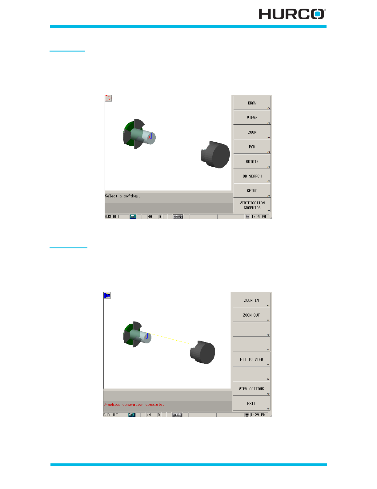
Draw Ke y
In addition to the Wireframe Graphics that appear on the Auto Run screen when running
a program, you can access Wireframe Graphics and view the part shape by pressing the
Draw console key. Select the Draw F1 softkey to display or re-draw the graphic.
Figure 1–21. Wireframe Graphics Screen
Veri fy K ey
You can access the Verification Graphics and view the tool path and stock removal of the
part by pressing the Verify console key. Select the Draw F1 so ftkey to display or r e-draw
the graphic.
Figure 1–22. Verification Graphics Screen
For information on u sing graphics with part programs, see Verifying Part Programs—
Graphics, on page 4 - 86.
Getting Started—WinMax Lathe Max Control v546GS Machine and Console Basics 1-37
Page 52
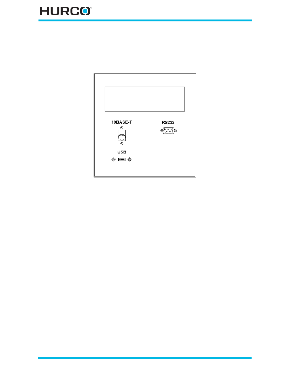
Communications Panel
Ea ch Hurco machine may be connected to peripheral de vices through a communications
panel located on the machine’s electrical cabinet.
Figure 1–23. Communications Panel
Communication connectors may include a USB port, a serial po rt, and a network
connector.
• The U SB p ort i s a hi gh -sp eed p ort th a t all ows you t o conn e ct mul tip l e devi ces
to the panel.
• The serial port is for sending and receiving serial data transmissions.
• The RJ45 connector is used for 10Base-T, unshielded twisted p air network
cabling.
Refer to the Maintenance and Safety Manual for Turning Centers for more information
about using the Communications Panel.
1 - 38 Machine and Console Basics v546GS Getting Started—WinMax Lathe Max Control
Page 53
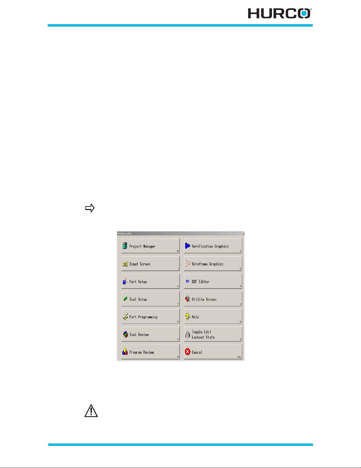
UTILITIES
Thi s se cti o n e xp la i ns ho w to c ust om i ze sys t em se tti n g s, ch an ge sc r ee n a pp ea rance, pri nt
whole programs or parts of programs, perform serial read/write functions, and manage
log files. These operations are accessed through the Utilities screen.
System Configuration . . . . . . . . . . . . . . . . . . . . . . . . . . . . . . . . . . . . . . . . 2 - 3
User Preferences . . . . . . . . . . . . . . . . . . . . . . . . . . . . . . . . . . . . . . . . . . . 2 - 10
Printing . . . . . . . . . . . . . . . . . . . . . . . . . . . . . . . . . . . . . . . . . . . . . . . . . . 2 - 24
Restart Control. . . . . . . . . . . . . . . . . . . . . . . . . . . . . . . . . . . . . . . . . . . . . 2 - 26
Shutdown Control. . . . . . . . . . . . . . . . . . . . . . . . . . . . . . . . . . . . . . . . . . . 2 - 26
Serial I/O . . . . . . . . . . . . . . . . . . . . . . . . . . . . . . . . . . . . . . . . . . . . . . . . 2 - 27
Log Files . . . . . . . . . . . . . . . . . . . . . . . . . . . . . . . . . . . . . . . . . . . . . . . . . 2 - 28
Select the Aux/Menu console key and this window with softkey selections appears on
the screen:
If using the WinMax Lathe Desktop softw are, select the F9 key to
access this screen.
Figure 2–1. Auxiliary Menu screen
Use the softkeys on the Auxiliary Menu screen to navigate to other parts of WinMax Mill.
This section describes the Edit Lockout Mode and the Utility Screen.
Before using the Toggle Edit Lockout State for the first time, be sure
to review Edit Lockou t Mode—First Use, on page 2 - 14 and be
familiar with how to use a password, set the desired level of access
restriction, enable, and disable the mode.
Getting Started—WinMax Lathe Max Control v546GS Utilities 2-1
Page 54
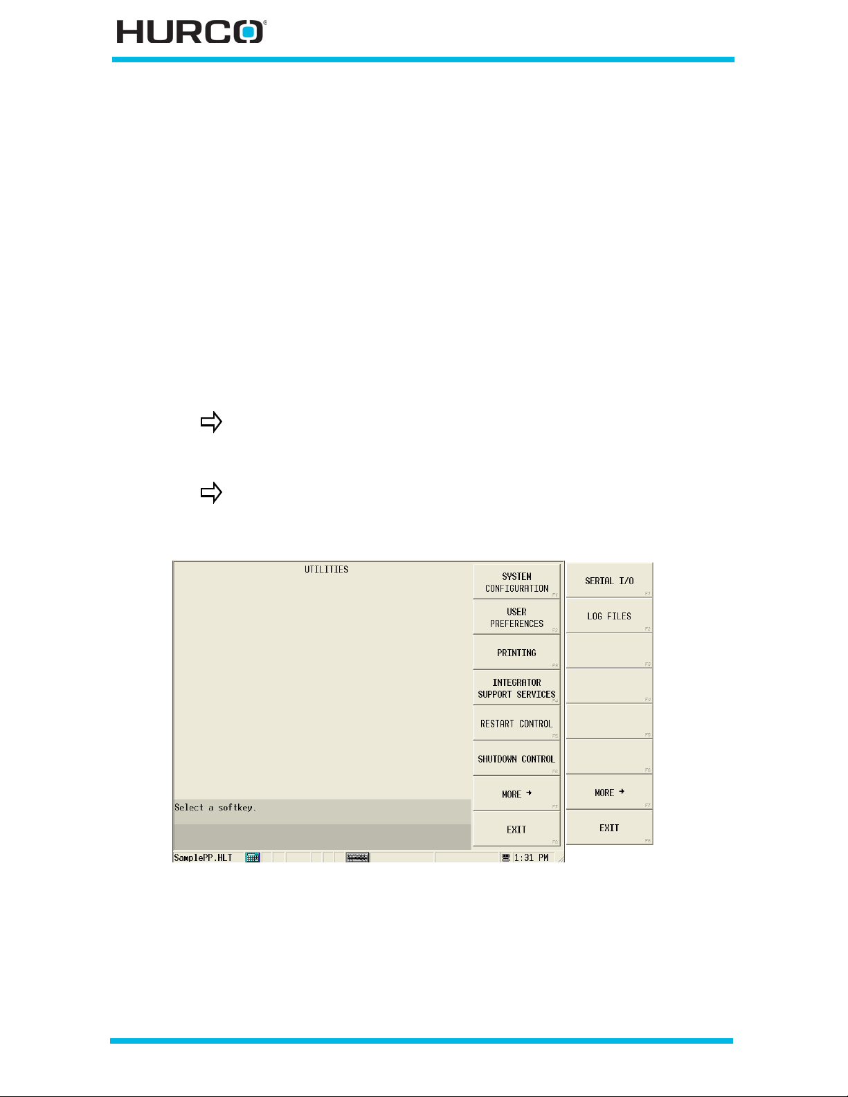
Utility Screen
Select the Utility Screen so ft k e y to ac ces s th e Ut i li ty sc ree n . Y ou can al so us e t he menu
toolbar and select the Utilities icon to access this screen. These functions are available
and are described in this section:
System Configuration . . . . . . . . . . . . . . . . . . . . . . . . . . . . . . . . . . . . . . . . 2 - 3
User Preferences . . . . . . . . . . . . . . . . . . . . . . . . . . . . . . . . . . . . . . . . . . . 2 - 10
Printing . . . . . . . . . . . . . . . . . . . . . . . . . . . . . . . . . . . . . . . . . . . . . . . . . . 2 - 24
Integrator Support Services. . . . . . . . . . . . . . . . . . . . . . . . . . . . . . . . . . . . 2 - 25
Restart Control. . . . . . . . . . . . . . . . . . . . . . . . . . . . . . . . . . . . . . . . . . . . . 2 - 26
Shutdown Control. . . . . . . . . . . . . . . . . . . . . . . . . . . . . . . . . . . . . . . . . . . 2 - 26
Serial I/O . . . . . . . . . . . . . . . . . . . . . . . . . . . . . . . . . . . . . . . . . . . . . . . . 2 - 27
Log Files . . . . . . . . . . . . . . . . . . . . . . . . . . . . . . . . . . . . . . . . . . . . . . . . . 2 - 28
Hurco recommends using the Shutdown Control command prior to
turning off machine power to ensure that no da ta is lost. Please re fer
to Shutdown Control, on page 2 - 26 for details.
The MORE F7 softkey accesses a second Utilities softkey menu.
Select MORE F7 to toggle between the two Utilities softkey
menus.
Figure 2–2. Utilities screen
2 - 2 Utilities v546GS Getting Started—WinMax Lathe Max Control
Page 55
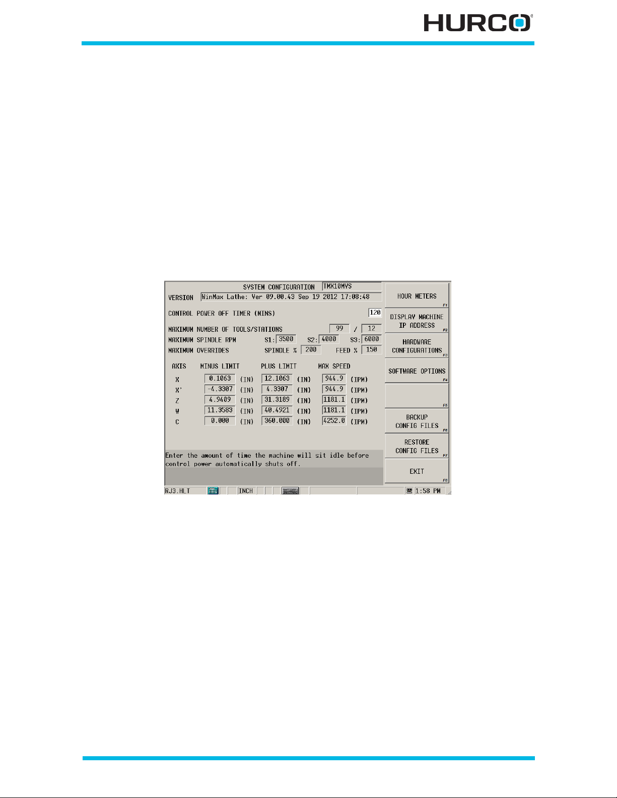
System Co n figu ration
Press the Aux/Menu key fo llowed by the Utility Screen softkey to access the Utilities
screen and softkey menu. From the Utilities screen, select the SYSTEM CONFIGURATION
F1 softkey to access the system settings. The System Configuration screen appears with
fields di sp layed based on the machine configuration. These functions are available from
the System Configuration softkey menu:
Hour Meters. . . . . . . . . . . . . . . . . . . . . . . . . . . . . . . . . . . . . . . . . . . . . . . 2 - 4
Machine Internet Protocol Address . . . . . . . . . . . . . . . . . . . . . . . . . . . . . . . 2 - 5
Hardware Configuration. . . . . . . . . . . . . . . . . . . . . . . . . . . . . . . . . . . . . . . 2 - 5
Software Options . . . . . . . . . . . . . . . . . . . . . . . . . . . . . . . . . . . . . . . . . . . 2 - 8
Configuration Fil es . . . . . . . . . . . . . . . . . . . . . . . . . . . . . . . . . . . . . . . . . . 2 - 8
Figure 2–3. System Configuration screen (TMX10MYS shown)
The majority of System Configuration screen fields contain values that reflect your
mach ine’s software version, maximum settings, limits, and a record of the spindle and
machine usage. However, you enter the value for the Control Power Off Timer field.
The machine type is displayed to the right of the System Configuration screen title. The
remaining fields are defined as follows:
• VERSION—displays the current s oftware version.
• CONTROL POWER OFF TIMER (MIN S)—contains the number of minutes
the machine can sit idle before the control power is automatically shut off.
The units for this field is minutes. The range is from 0 to 600.
• When 0 is entered, the timer is off. In other words, there is no time out.
• When a number from 1 to 600 is entered, that number represents the
number of minutes th e machine can sit idle before shut ting off the contro l
powe r.
Getting Started—WinMax Lathe Max Control v546GS Utilities 2-3
Page 56
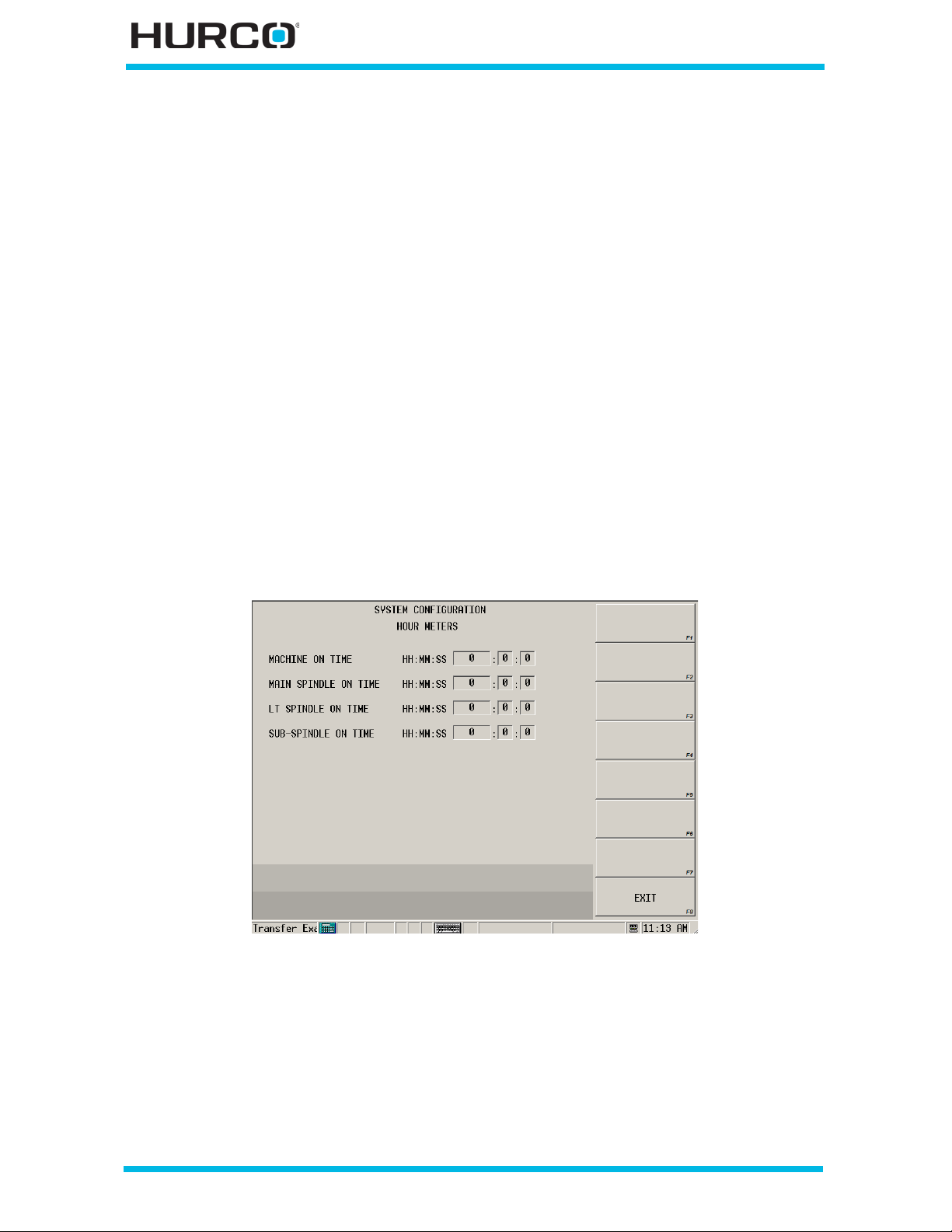
• MAXIMUM NUMBER OF TOOLS/STATIONS—displays the number of tools
and stations that can be programmed.
• MAXIMUM SPINDLE RPM—displays the highest possible spindl e rpm speed
for each spindle.
• MAXIMUM OVERRIDES—displays the highest possible override percentage
for spindl e sp eeds and feedrate that programs can run.
• SPINDLE %. This setting overrides the manual setting on the Spindle
Speed dial.
• FEED %. This setting overrides the manual setting on the Axis Feed dial.
• AXIS MINUS LIMIT, P LUS LIMIT, MAX SPEE D—display the maximum
limit setting for each of these points. Axes are displayed based on the
machine configuration.
Hour Meters
The software tracks the amount of time the machine is on and the amount of time each
spin dl e runs .
Select the HOUR METE RS F1 softkey on the System Configuration screen to display the
Hour Meters screen. Select the Exit F8 softkey to return to the System Configuration
screen.
Figure 2–4. Hour Meters screen
The fields on this screen are displayed ba sed on the machine configuration. They are
defined as follows:
• MACHINE ON TIME—displays how many hours, minutes, and seconds the
machine has had control power on since the machine was commissioned.
• MAIN SPINDLE ON T IME—d is pla ys how ma ny hour s, minu te s, an d s econ ds
the main spindle has been run since the machine was commissioned.
2 - 4 Utilities v546GS Getting Started—WinMax Lathe Max Control
Page 57
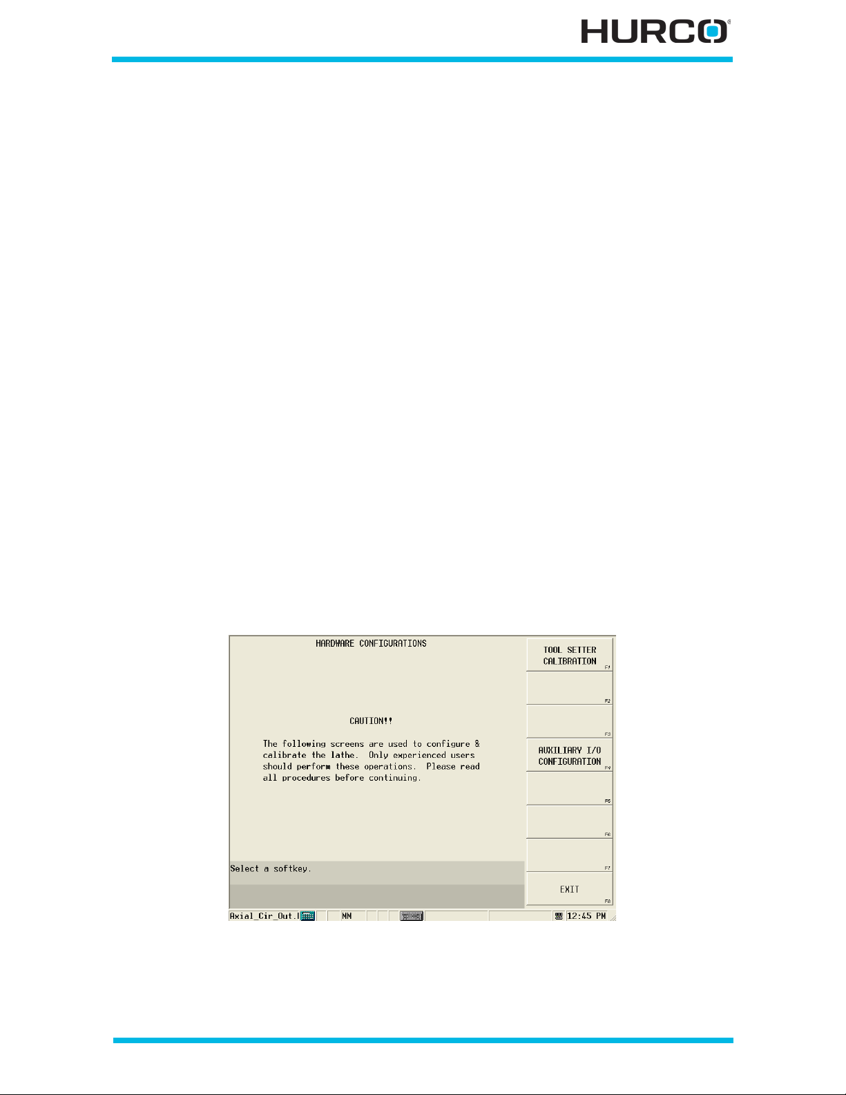
• LT SPINDLE ON TIME—dis pla ys how man y ho ur s, m inut es , a nd sec o nds th e
live-tooling spindle has been run since the machine was commissioned.
• SUB-SPINDLE ON TIME—displays how many hours, minutes, and seconds
the sub-spindle has been run since the machine was commissioned.
Mach ine Intern et Protoco l A ddre ss
An IP (Internet Protocol) address is used to identify a particular host on a network. Each
host on a network must have a unique IP address consisting of a 32-bit number usually
presented in dotted decimal format; for example, 200.100.150.1. This format divides the
address into four single byte values separated by decimal points. On most networks, the
first three bytes represent the network and the last byte is the host. Following this
practice, the first three bytes are the same for all hosts and the last byte is different for
each host. On the Inte rnet, these cr yptic addresse s usually are n ot used—most add resses
are represented as plain text, which are converted to IP addresses by DNS, or Domain
Name Server. The underlying protocol still uses the unique 32-bit IP addresses.
Select the DISPLAY MACHINE IP ADDRESS F2 softkey on the System Configuration
screen to display the machine’s IP address in a pop-up window. Select OK in the window
to close the pop-up window.
Hardware Configuration
The Hardware Configurations screen provides access to tool setter calibration, along with
auxiliary input and output configurations to enable auxiliary equipment or a unique
machine function. To access the Hardware Configuration softkey menu, select the
HARDWARE CONFIGURATIONS F3 softkey on the System Configuration screen. This
scre en appe ar s:
Figure 2–5. Hardware Configurations screen
Getting Started—WinMax Lathe Max Control v546GS Utilities 2-5
Page 58
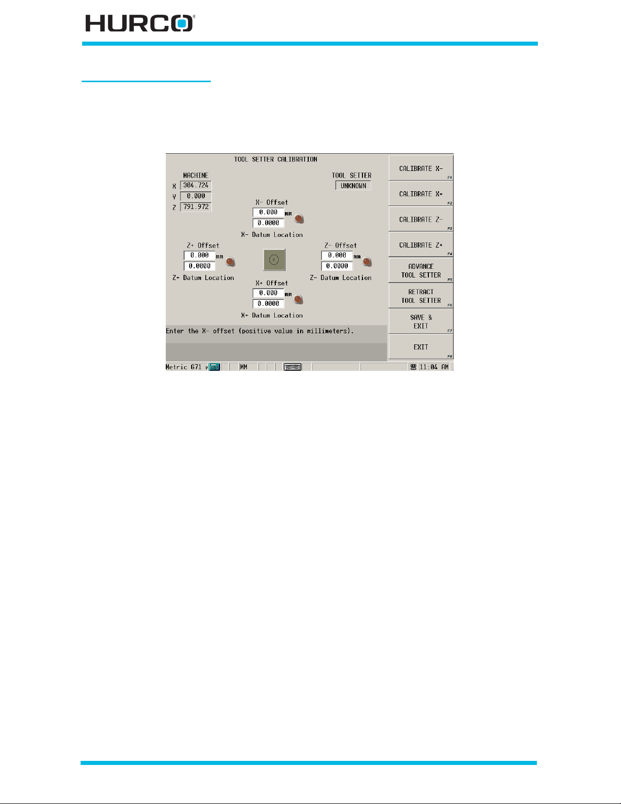
Tool Setter Calibration
Select the TOOL SETTER CALIBRATION F1 softkey on the Hardware Configurations
screen to configure the To ol Setter option. Refer to WinMax Lathe Options Tool Setter, on
page 16 - 1 for information about this feature.
Figure 2–6. Tool Setter Calibration screen
Auxi li ary I/O Configuratio n
Select the AUXILIARY I/O CONFIGURATION F4 softkey on the Hardware
Configurations screen to access the Auxiliary I/O C onfiguration screen, which in turn
accesses four (4) Auxiliary Input/Output Configuration screens from these softkey
choices:
• OUTPUT 1 (M52 / M62) F1
• OUTPUT 2 (M53 / M63) F2
• OUTPUT 3 (M54 / M64) F3
• OUTPUT 4 (M55 / M65) F4
Individually enable auxiliary equipment or a unique machine function from within a part
program with these screens. Each of these screens allows you to program M codes for
turning On and Off an auxiliary feature:
• M52 (on) / M62 (off)
• M53 (on) / M63 (off)
• M54 (on) / M64 (off)
• M55 (on) / M65 (off)
2 - 6 Utilities v546GS Getting Started—WinMax Lathe Max Control
Page 59
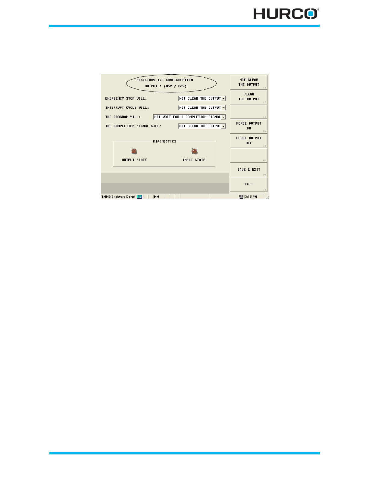
A screen like the sample below appears for each output selection. Each screen shows its
Output M code s in its heading (circled in the sample).
Figure 2–7. Auxiliary I/O Configuration Output screen
Program the auxiliary device using the fields and softkeys. When the following selections
are made, the M codes will turn on and off the device as described in these fields:
• EMERGENCY STOP WILL—select either NOT CLEAR THE OUTPUT or CLEAR
THE OUTPUT. When the Emergency Stop state is active, the state of the
output is based on the selection here.
• INTERRUPT CY CLE WILL—select either NOT CLEAR THE OUTPUT or CLEAR
TH E OUT PUT. While a part program is ru nning and the Interrupt Cycle
button is pressed, the state of the output is based on the selection here.
• THE PROGRAM WILL—s elect either NOT WAIT FOR A COMPLETION SIGNAL
or W AIT F OR A COMP LET ION SIGNA L . If W AIT FO R A COMP LET ION SIGNAL i s
selected, the part program will wait at the M Code for the appropriate Input
to go high.
• THE COMPLETION SIGNAL WILL—select either NOT CLEAR THE OUTPUT
or CLEAR THE OUTPUT upon completing the part program. If CLEAR THE
OUTPUT is selected, the Output will be automatically tu rned off when the
appropriate Input goes to a high state.
To check that the logic is functioning properly and test the state of the circuitry, these
softkeys are available on the Auxiliary I/O Configuration screen:
• FORCE OUTPUT ON F4—the Output State on-screen LED turns green when
this softkey is selected.
• FORCE OUTPUT OFF F5—the Input State on-screen LED turns red when thi s
softkey is selected.
Getting Started—WinMax Lathe Max Control v546GS Utilities 2-7
Page 60
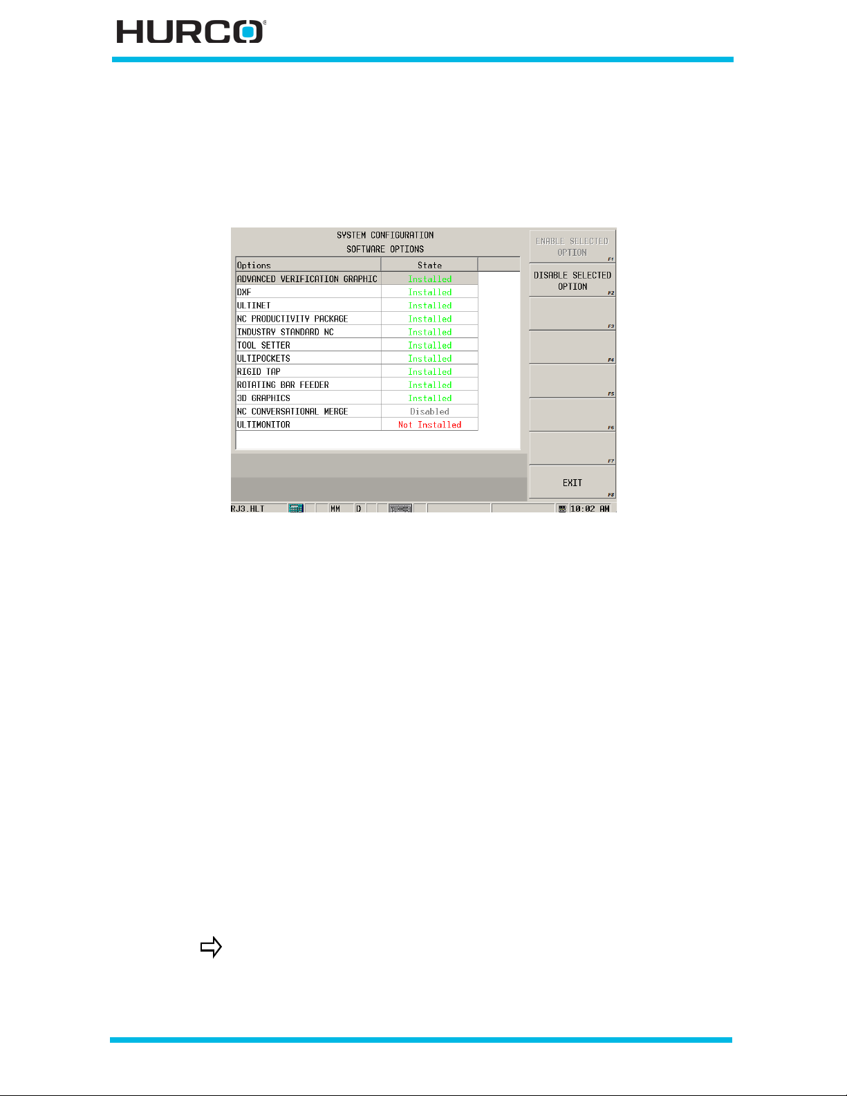
Software Options
The Software Options screen allows you to view which software options are installed. In
addition, options may be temporarily disa bled and enab led again using the DISABLE
SELECTED OPTION F2, and the ENABLE SELECTED OPTION F1 softkeys.
Figure 2–8. Software Options screen
Configuration Files
Machine Configuration files should be backed up upon completion of a software upgrade.
Select the BACKUP CONFIG FILES F6 softkey on the System Configuration screen to
copy machine con figuration files onto a floppy diskette, USB storage device, or network
drive.
Follow th ese steps to backup the Configuration files:
1. Determine the type of storage device for co pyi ng the Machine Configuration
files from the control.
• Insert the floppy disk for cont aining the configuration files into the floppy
drive.
• Insert the USB stora ge device for containing the configuration files into
the USB port.
• Select a network drive for containi ng the configuration files on the
control.
2. From the System Co nfiguration screen, selec t the BA CKUP C O N F I G F I L E S F6
softkey.
When you copy a file using a storage device or network drive, a popup window appears for choosing the location for the files to be copied.
2 - 8 Utilities v546GS Getting Started—WinMax Lathe Max Control
Page 61

3. Re move the storage device when the backup is complete, an d store it in a safe
location.
If you use a network drive, be sure it is in a safe, secure location.
Previ ously saved machine configuratio n data can be used to restore machine
configuration files in the event that the control hard drive is replaced. Select the
RES TORE C ONFI G FIL ES F7softkey on the System Configuration screen to restore this
data.
Follow these steps to restore the Configuration files:
1. Insert the storage device containing the back up c onfiguration f iles.
2. From the System Configuration screen, select the RESTORE CONFIG FILES
F7 softkey.
When you restore a file using a storage device or network drive, a
pop-up window appears for choosing the location for the files to be
copied.
3. The system reboots when configuration files are restored. The software
displays a pop-up message asking if it is OK to reboot now.
• Select OK to continue or Cancel to stop the process.
4. Remove the storage device when the restoration is complete, and store it in a
safe location.
If you use a network drive, be sure it is in a safe, secure location.
Getting Started—WinMax Lathe Max Control v546GS Utilities 2-9
Page 62
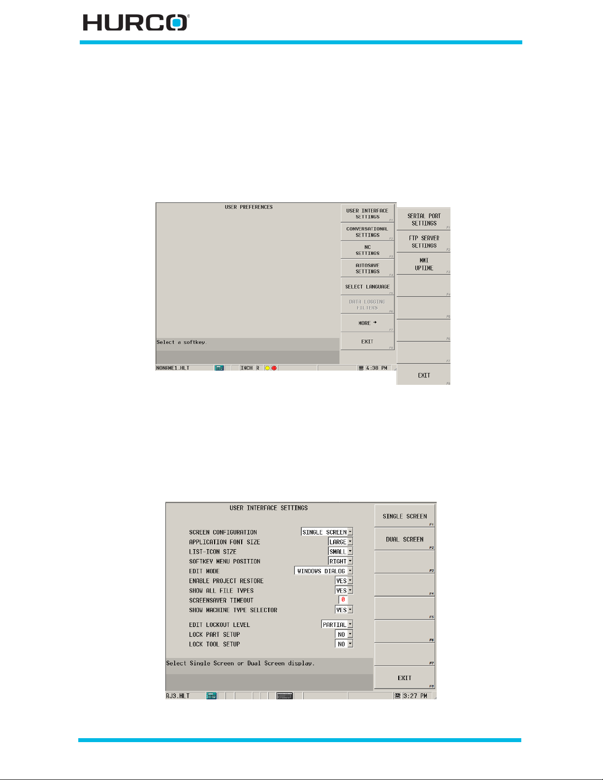
User Pref erence s
Press the Aux/Menu key fo llowed by the Utility Screen softkey to access the Utilities
screen and softkey menu. From the Utilities screen, select the USER PREFERENCES F2
softkey. The User Preferences menu accesses softkey menus for changing screen
setting s. Selec t the MORE F7 softkey to access additional user preferences. Select EXIT
F8 on the second menu to return to the first m enu. The EXIT F8 softkey on the first men u
returns to the Utilities screen.
Figure 2–9. User Preferences screen
User Interface Settings
The USER INTERFACE SETTINGS F1 softkey accesses a screen with the following fields.
Change the screen appearance or behavior with the User Interface Settings selections.
Figure 2–10. User Interface Settings screen
2 - 10 Utilities v546GS Getting Started—WinMax Lathe Max Control
Page 63

For all of these fields, you can either use softkeys or the drop-down list to make
selections.
• SCREEN CONFIGURAT ION—select Single Screen or Dual Screen for the
type of s creen used for the screen d isplay. If changing the configuration, the
software must be restarted to take effect. This field is available only on the
desktop version of the software. This field is read-only on machine consoles.
• APPLICATION FONT SIZE—select Large or Small for the size of the font
used on the screen display. This field is available only on the desktop version
of the software.
• LIST- ICON SIZE—select Large or Small.
• SOFTKEY M ENU POSITION—select Right or Left and the softkey menus
appear on the side of the screen that you select.
• ED IT MODE—provides a choice between Windows and Ultimax editing
behavior. The software defaults to Ultimax Classic.
• Ultimax Classic—operates like previous Hurco Ultimax products, i.e.,
when you input data, you must press the Enter key for the software to
accept the da ta.
Sele ctio ns made in drop- dow n lists do no t req uir e pr essin g the En t er
key in Ultimax C lassic mode.
• Windows Dialog—operates like Windows software product s. The
software accepts data selected in an edit box or typed in a field without
having to use the Enter key.
• ENABLE PROJECT RESTORE—select Yes and all programs that are open
upon machine power off will re-open for the next machine power on. Select
No and all programs will close upon machine power off and will not be
restored upon machine power on. If No is selected, AutoSave will not restore
the program either.
• SHOW ALL FILE TYPES—select Yes or No for all file types to appear in the
Project Manager screen when opening files.
The Show All File Types field must be set to YES in order to see the
PDF files in the directory in which the Help documentation is stored.
Please refer to Ac ce ss in g the Wi nM ax He l p i n PD F f or m at f o r pr in ting,
on page 1 - 13 for information about printing the Help.
• SCREENSAVER TIMEOUT—Determine how long the console can remain idle
before the screen goes blank. Enter a time in minutes i n this field. The screen
will go blank after the entered time if console keys or buttons are not
selected.
To re-display blank screens, touch the screen or press any console
key. The firs t ke y or to uch is u sed to re- activate the bl ank screen and
will not activate the key or softkey pressed.
• SHOW MACHI NE TYPE SELE CTOR—select Yes for the S creen Typ e Selector
window to appear upon launching the WinMax Lathe desktop software. The
selected machine type will also appear on the Input screen of the desktop
software. This field appears only for the desktop software.
• ED IT LOC K OUT LEVEL—sets the level of editing protection, Partial or Full,
Getting Started—WinMax Lathe Max Control v546GS Utilities 2-11
Page 64

to limit access to part programming softkeys and other functions when the
Edit Lock out featu re is enabled using the Toggle Edit Loc ko ut Sta te softke y
located on the Auxiliary Menu screen. Please refer to Edit Lockout Mode—
First Use, on page 2 - 14 for information about setting this mode.
With the Edit Lockout State enabled, these selections may be applied:
• PARTIAL—prevents changes to the part program. In addition, changes in
Tool Se tup are not automatically updated in the part program. When
Partial is selected, the Lock Part Setup and Lock Tool Setup fields are
available for selecting Yes or No.
• LOCK PART SETUP—with the Edit Lockout Level set to Partial, select
YES to prevent changes to Part Setup in addition to preventing
changes to the par t program. S elect No to allow changes to Part S etup
while preventing changes to the part program.
• LOCK TOOL SETUP—with the Edit Lockout Level set to Partial, select
YES to prevent changes to Tool Setup in addition to preventing
changes to the part program. Select No to allow changes to Tool Setup
while preventing changes to the part program.
• FULL—prev ents c hang e s to th e par t pr ogra m , Pa rt Se t up a n d T o ol Se tu p.
When Full is selected, the Lock Pa rt Setup and Lock Tool Setup fields
are not available (grayed out). In addition, the Cycles Completed field on
the Auto (Conversational) screen is not available for editing.
Refer to Table 2–1.Edit Lockout Mode Feature Accessibility, on page
2 - 13 for a complete listing of features that are affected by partial
and full lockout.
You will be redirected to the Input screen if you are on a screen that
becomes locked out when you enter the password.
2 - 12 Utilities v546GS Getting Started—WinMax Lathe Max Control
Page 65
Here is a feature comparison of Edit Lockout Mode On with Partial or Full Level selected,
and Edit Lockout Mode Off status:
Feature
Edit Lockout Mode On
Partial Level Full Lev el
Edit Lockout
Mode Off
Part Programmin g Locked Locked Accessible
Program Parameters Locked Locked Accessible
Pr ogram Rev iew:
Locked Locked Accessible
Multip le Block Functions
(Copy, Paste, Insert, Delete)
DXF Locked Locked Accessible
DB Search / Block Jump Locked Locked Accessible
Jump to Block
Locked Locked Accessible
(from Error Message)
Part Setup—Work Offset s Accessible with
Locked Accessible
Lock Part Setup
set to No
Tool Setup Accessible with
Locked Accessible
Lock Tool Setup
set to No
Tool Offsets Accessible with
Locked Accessible
Lock Tool Setup
set to No
User Pre ferences Accessible Locked Accessible
Part Counter Accessible Locked Accessible
Table 2–1. Edit Lockout Mode Feature Accessibility
Additional Edit Lockout considerations:
• Runtim e modifica tion s—Edit Lockout does not prevent a running program
from modifying setup or itself. For instance, if the program uses macros that
manipulate program variables or part or tool setup directly, this is allowed.
• Overrides—Feed overrides are controlled by the Feed Override Lockout
parameter in Program Parameters. Since Program Parameters are not
accessible in Partial or Full lockout mode, Feed Override Lockout should be
set to YES so overrides cannot be adjusted while running the program.
Getting Started—WinMax Lathe Max Control v546GS Utilities 2-13
Page 66

Edi t Lockout Mode—First Use
Prior to setting the state of the Edit Lockout Mode to On, the password should be reset
from the factory default (HURCOLOCK).
Setting Edit Lockout Level P ref erences
Set Edit Lockout Level to Partia l or Full on the User Interface Settings screen:
1. Select the Aux/Menu console key. The Auxiliary Menu screen opens.
2. Select the Utility Screen softkey.
3. Select the User Preferences softkey.
4. Select the User Interface Settings softkey. The User Interface Settings
scre en appe ar s.
5. Place the cursor in the Edit Lockout Level field. Select Partial or Full. When
Partial is select ed, the Lock Part Setup and Lock Tool Setup fields are availab le
so you can also lock out Part Setup and/or Tool Setup.
You will be redirected to the Input screen if you are on a screen that
becomes locked out when you enter the password.
Reset P assword
1. Select the Aux/Menu console key. The Auxiliary Menu screen opens.
2. Select the Utility Screen softkey.
3. Select the User Preferences softkey.
4. Select the User Interface Settings softkey. The User Interface Settings
screen appears. When the cursor is in the Edit Lockout Level field, the
Cha n ge Lockout Pass word softkey is available.
Figure 2–11. User Interface Settings, Change Lockout Password softkey
2 - 14 Utilities v546GS Getting Started—WinMax Lathe Max Control
Page 67

5. Select the Change Lockout Password softkey. A pop-up window appears with
fields for entering the old password, new password, and new password
confirmation.
6. Enter the information into the fields and select OK to save the changes.
Rememb er the new password!
You will be redirected to the Input screen if you are on a screen that
becomes locked out when you enter the password.
Enable Edit Lockout Mode
1. Select the Toggle Edit Lockout State softkey located on the Auxiliary Menu
screen. When the softkey is selected, a pop-up box appears prompting for the
password.
2. Enter the password and select OK. The Edit Lockout featur e is enabled, and a
confirmation message appears. Please refer to Setting Edit Lockout Level
Preferences, on page 2 - 14 fo r details about Partial and Full lock out levels.
Disable Edit Lockout Mode
1. Select the Toggle Edit Lockout State softkey located on the Auxiliary Menu
screen. When the softkey is selected, a pop-up box appears prompting for the
password.
2. Enter the password and select OK. The Edit Lockout feature is disable d, and a
confirmation message appears. Please refer to Setting Edit Lockout Level
Preferences, on page 2 - 14 fo r details about Partial and Full lock out levels.
Getting Started—WinMax Lathe Max Control v546GS Utilities 2-15
Page 68
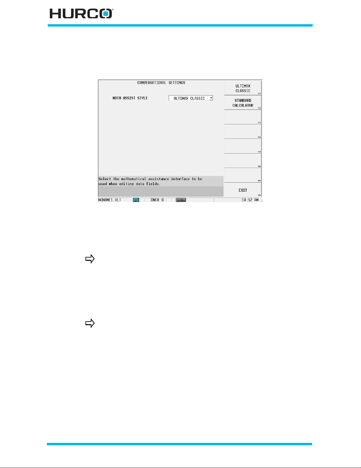
Conversational Settings
The CONVERSATIONAL SETTINGS F2 softkey accesses this screen:
Figure 2–12. Conversational Settings screen
• MATH ASSI ST STYLE—select Ultimax Classic or Standard Calculator.
• ULTIMAX CLASSIC—uses an operating logic that uses the Enter key to
perform functions.
Examples of Ultimax Classic Math Assist:
• If a field contains a value of 5 and you type “-2” the 5 changes to
“-2.”
• If a field contains a value of 5 and you type “2-” the 5 changes to
“3.”
• STANDARD CALCULATOR—works like a calculator.
Examples of Standard Calculator Math Assist:
• If a field contains a value of 5 and you type “-2” the 5 changes to
“3.”
• If a field contains a value of 5 and you type “2-” the 5 changes to
“2” because t he control expects a second value to be subtracted
from 2.
2 - 16 Utilities v546GS Getting Started—WinMax Lathe Max Control
Page 69
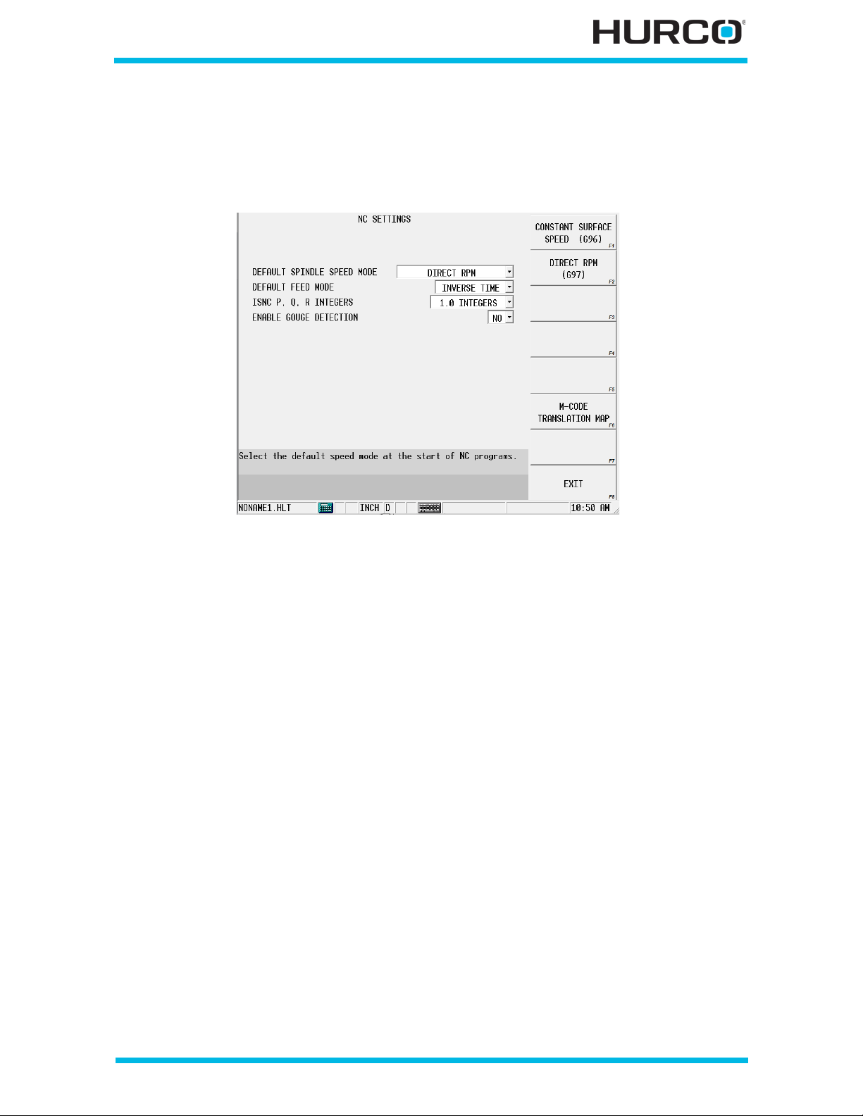
NC Settings
The NC SETTINGS F3 softkey accesses the screen to select default settings for NC
Programs:
Figure 2–13. NC Settings screen
• DEFA UL T S PIND L E SP EED MODE —select Constant Surface Speed (G96) or
Direct RPM (G97).
• DEFAULT FEED MODE—select Inverse Time, Per Minute, or Per Revolution.
This field specifies the mode assumed by the part program interpreter when
either G93 (inverse time), G94 (per minute), or G95 (per revolution) is not
programmed.
• ISNC P, Q, R INTEGERS—s elect the units t he P, Q, and R valu es use with no
decimal point (tenths, hundredths, or thousandths).This field appears for
ISNC.
• ENABLE G OUGE DETECTION—sele ct Yes or No to enable gouge protection
when running NC programs. This field is available for ISNC.
• M-CODE TRANSLATION MAP Softkey—opens M-Code Translation Map
table. See M Code Tr anslation, on page 5 - 2.
Getting Started—WinMax Lathe Max Control v546GS Utilities 2-17
Page 70
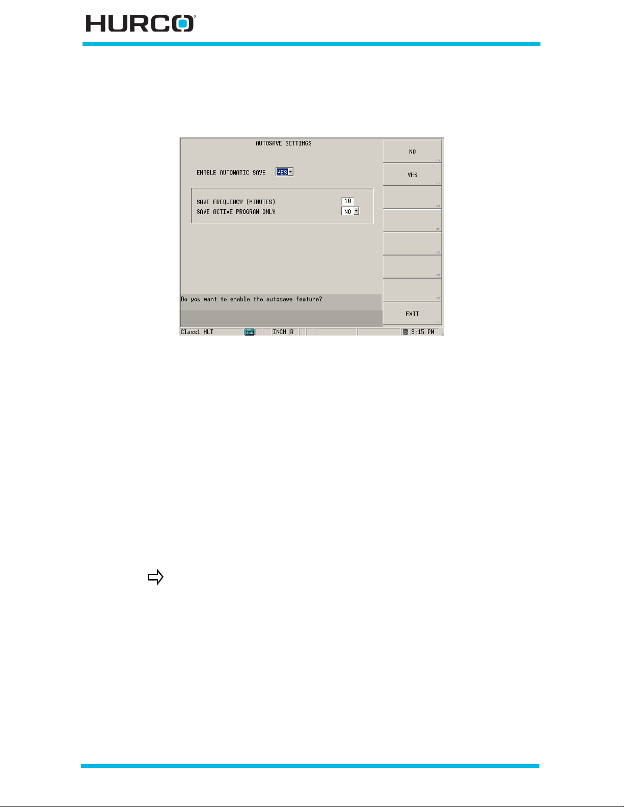
AutoSave Settings
The AutoSave F4 softkey accesses the AutoSave Settings screen.
Figure 2–14. AutoSave Settings screen
Use the AutoSav e feature to periodically save a copy of the Conversational part program.
While the part program is being saved, the system displays the “Autosaving Part
Program” message.
• ENABLE AUTOMATIC SAVE—select Yes or No.
• SAVE FR EQ UEN C Y (M I NUTES )—en ter the minutes to sp ecify th e fre quency
for saving files if enabled.
• SAVE ACTIVE PROGRAM ONLY—select Yes to specify if only the active
program should be saved or No if all open programs should be saved.
Programming changes made after the last AutoSave are lost if the machine is powered
off. Whe n the machine power is on and the User Inter face Setting s screen, Enable P roject
Restore field is set to Yes, the last AutoSave version of the program automatically
appears on the screen.
AutoSave does not save a program to its original program name or
drive. Refer to Save Files, on page 3 - 5 for instructions on saving a
program.
2 - 18 Utilities v546GS Getting Started—WinMax Lathe Max Control
Page 71
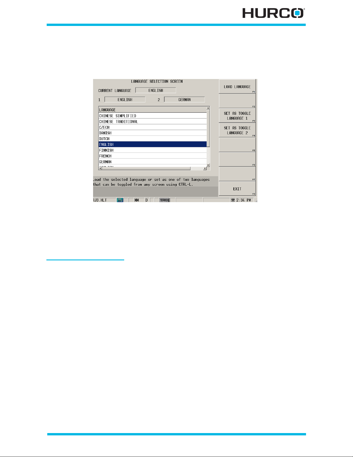
Select Language
The SELECT LANGUAGE F5 softkey accesses the Language Selection screen.
Figure 2–15. Language Selection screen
1. Select a language from the list.
2. Select the Load Language softkey to install the Language files. The selected
language appears in the Current Language field.
Language Quick Toggle
You can toggle between two languages from any screen in WinMax using the Language
Quick Toggle feature. To set the primary and secondary languages, highlight a lang uage
in the list and select the Set as Toggle Langua ge 1 softkey (for primary language) or
Set as Toggle Lan guage 2 softkey (for secondary language). The selected languages
are shown at the top of the screen.
Use Ctrl + L on the keyboard or pop-up keyboard to switch back and forth between the
languages o n any screen in WinMax.
Getting Started—WinMax Lathe Max Control v546GS Utilities 2-19
Page 72
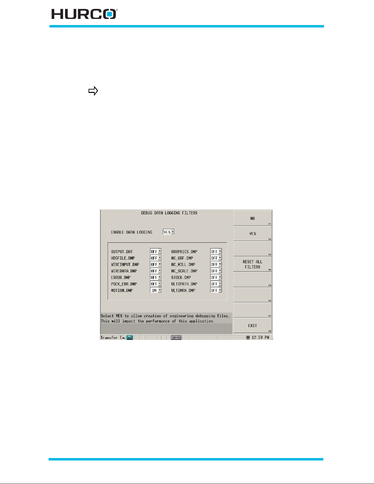
Data Logging Filters
From the User Preferences screen, select the DATA LOGGING FILTERS F6 softkey to
access the Debug Data Logging Filters screen.
This screen assists Hurco Engineering with software tr oubleshootin g.
Files are created from the selections, providing system information.
When NO is selected in the Enable Data Logging field, none o f the filter selections are
active. NO is the default. This field resets to NO each time the WinMax software restarts.
Select YES and the message “Warning: Enabling data logging will reduce performance.”
Select OK to close the message. The filters are available to be selected. Performance is
slowed based on the number of filters selected.
A file is written for each selected filter (*.DMP file). If Enable Data Logging is set to No
after filters have been selected, the filters with ON selected will still be ON, but log files
are not created unless Yes is selected for Enable Data Logging.
These files are s tored in a folder on the control’s Hard drive here: C:\LatheDumpFiles.
Figure 2–16. Data Logging Filters screen
2 - 20 Utilities v546GS Getting Started—WinMax Lathe Max Control
Page 73
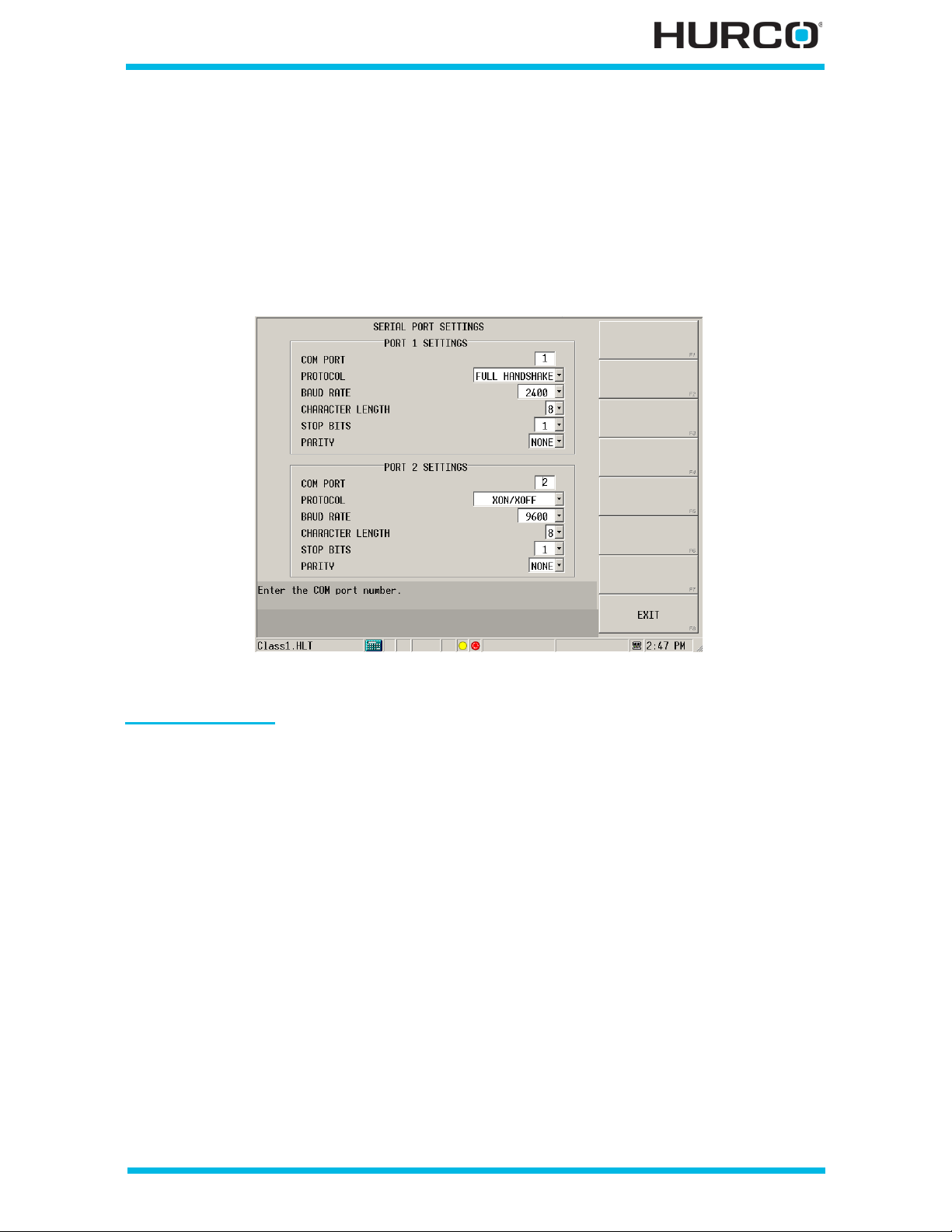
Serial Port Settings
From the User Preferences screen, select the More F7 softkey to access the SERIAL
PORT SETTINGS F1 softkey and the Serial Port Settings screen. Two serial port settings
are available for transferring part programs between the control and various peripheral
devices, such as a PC or an external disk drive. Make selections for mapping serial ports
and settin g Protocol, Baud Rate, Character Len gth, Stop Bits, and Par ity for both ports on
this screen.
Figure 2–17. Serial Port Settings screen
Serial Port Setup
• COM PORT—map each port as desired by entering the appropriate serial
port. The range is 1 through 256.
• PROTOCOL—identifies the method that data is transferred between two
devices. “Handshaking” is another term for protocol. T he CNC uses hardware
and software protocols. An operator writing communications utilities will find
this info rma ti on us eful . He re ar e desc rip tio ns of t he types of Pro toc ol yo u can
select from the Protocol field:
• CTS/RTS—identifies the hardware flow control method as Clear to Send/
Request to Send.
• XON/XOFF—identifies the protocol using a software flow control method.
• FULL HANDSHAKE—identifies the protocol using a software flow control
method similar to XON/XOFF. Th e difference lies in the synchronization
stage of Full Handshake.
Getting Started—WinMax Lathe Max Control v546GS Utilities 2-21
Page 74
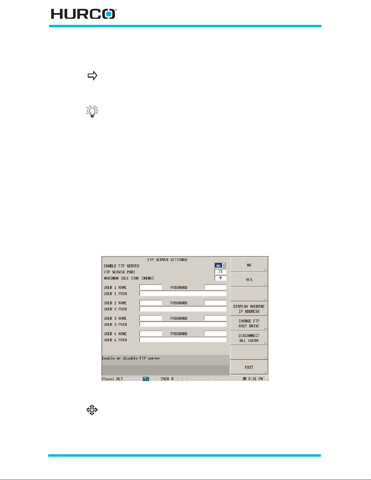
• BAUD RATE—determines how fa st data is transferred between two serial
mode ms. Choose between seven baud rates using the drop-down list or
softkeys. The baud rate is measured in characters per second.
Improper cable connections and incompatible communications
settings are the most common problems that prevent
communication between two electronic devices. Refer to the Parts
Listing and Wiring Diagrams manual for cabling requirements.
Always use your fastest computer for transferring programs to the
CNC.
Conversational and NC programs can be transferred between the
CNC’s memory and peripheral devices.
• CHARACT ER LENGTH—choose between 7 character bits or 8 character bits
for Conversational or NC programming using the softkeys or drop-down list.
• STOP BITS—choose between 1 and 1.5 stop bits for Conversational or NC
programming using the softkeys or drop-down list.
• PARITY—choose among None, Odd, or Even for Conversational or NC
programming using the softkeys or drop-down list.
FTP S erver S ettings
From the User Preferences screen, select the More F7 softkey to access the FTP
SERVER SETTINGS F2 softkey and the FTP Server Settings screen.
Figure 2–18. FTP Server Settings screen
Refer to WinMax Lathe Options UltiMonitor, on page 17 - 1 for
information about this option.
2 - 22 Utilities v546GS Getting Started—WinMax Lathe Max Control
Page 75
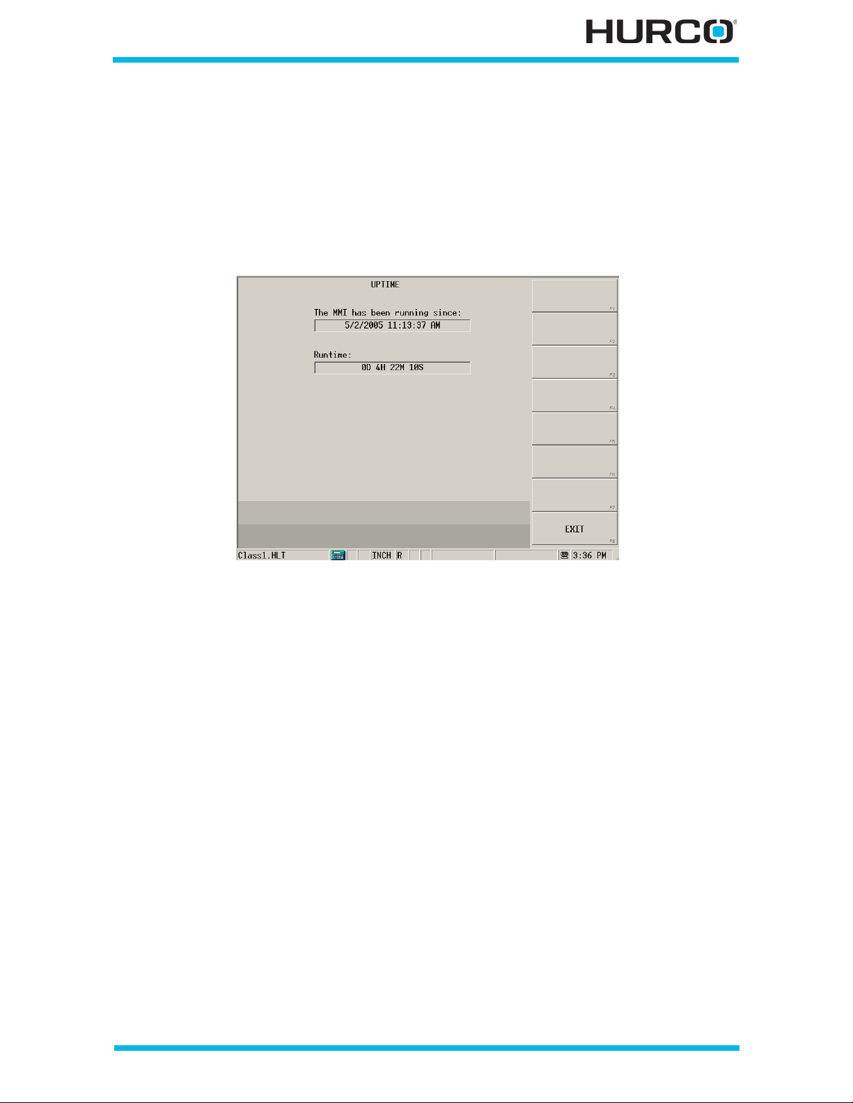
MMI Uptime
From the User Preferences screen, select the More F7 softkey to access the MMI
UPTIME F3 softkey to show the UPTIME screen. This screen shows the date and time the
MMI (Man-Machine Interface, or software screen) began running. The Runtime field
displays the number of days (D), hours (H), minutes (M) and seconds (S) for machine
power on. Refer to Power Up, on page 5 - 2 for more information about machine and
control power.
Figure 2–19. Uptime screen
Getting Started—WinMax Lathe Max Control v546GS Utilities 2-23
Page 76
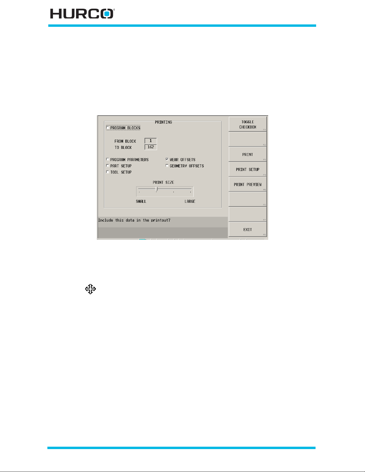
Printing
Press the Aux/Menu key fo llowed by the Utility Screen softkey to access the Utilities
screen and softkey menu. From the Utilities screen, select the PRINTING F3 softkey to
access the Printing screen. The Pri nting screen allows you to print sections of programs
or entire part pr ograms from the console. You can connect a printer to the machine usin g
the USB port or print to a networked printer.
Figure 2–20. Printing screen
Use the arrow keys to move to each field or select a field with the stylus. Then use the
TOGGLE check box F1 softkey for making selections to include when printing programs.
Refer to Programming Basics, on page 4 - 1 for information about
part programs.
You can print the entire program by selecting all of the check boxes or only select boxes
for the pa rts of the program you wish to print. The following fields are available on the
Printing screen for selecting programming information to include when printing:
• PROGRAM BLOCKS—you can either select Program Blocks to print all
blocks, or you can identify a range of blocks to pr int in the FROM BLOCK and
TO BLOCK fields.
• PROGRAM PARAMETERS
•PART SETUP
• TOOL SETUP
• WEAR OFFSETS
• GEOMETRY OFFSETS
• PRINT SIZE—mov e the slider fr om SMALL to LARGE to adju st the size of the
printed text.
2 - 24 Utilities v546GS Getting Started—WinMax Lathe Max Control
Page 77
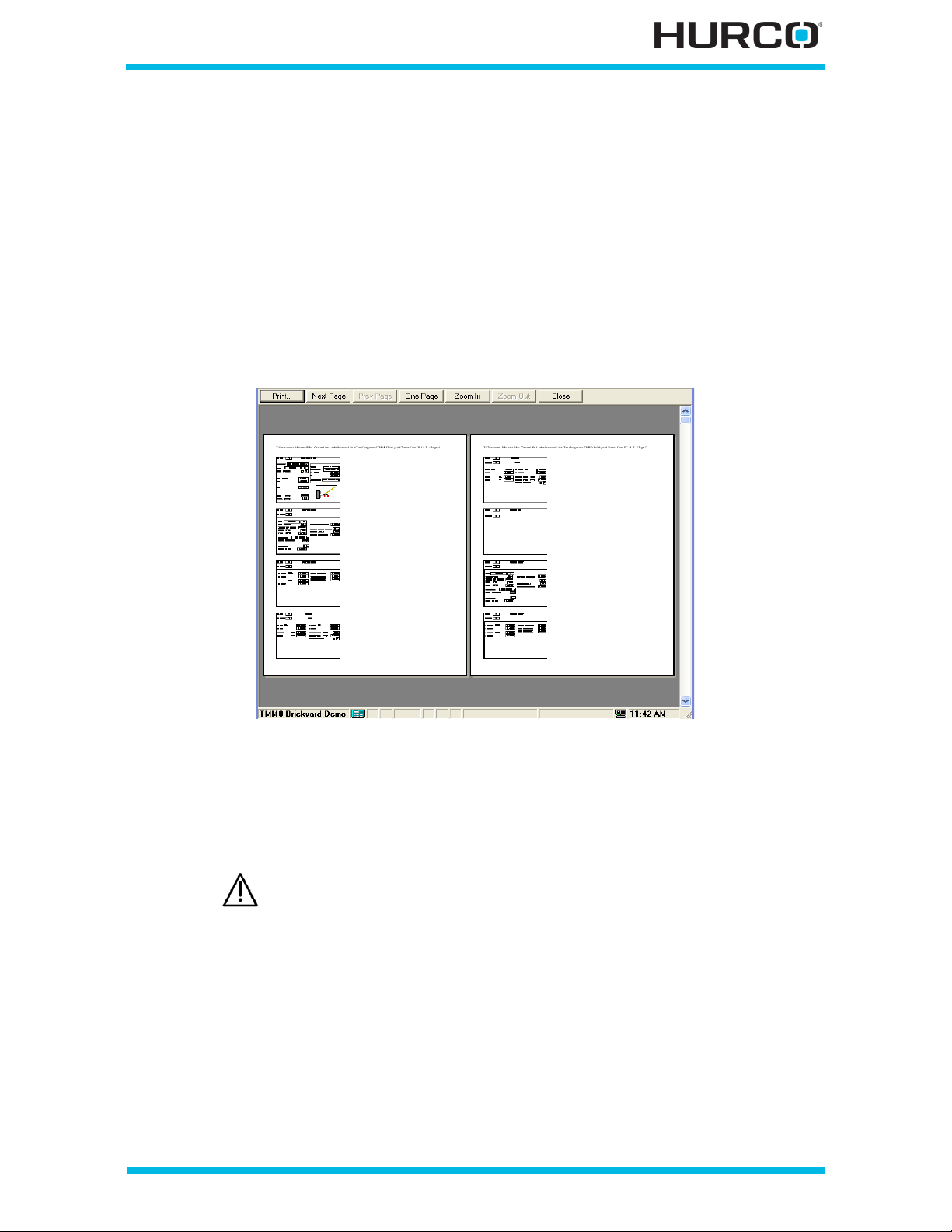
These softkeys are available on the Printing screen:
• TOG GLE CHECKBOX F1—select which sections of the current program to
print.
• PRINT F3—display the Print pop-up window for entering printer selections.
This is a standard Windows dialog for selecting a printer, print range, and
number of copies.
• PR INT SE TUP F4—display the Print Setup pop-up window for entering setup
selections, such as printer, paper size, and orientation.
• PRINT PREVIEW F5—display a preview of the print selection. Use the
softkeys that appear at the top of this preview sc reen to view di fferent pages,
zoom, and print.
Figure 2–21. Print Preview screen
Integra tor Support Services
The Integrator Support Services screen is for Hurco Certified
Technic i ans use only in configuring and setting up the machine.
This screen is password protected. Unauthorized access to this area and changing
machine settings may result in i mproper machine operatio n and/or damage to the
machine.
Getting Started—WinMax Lathe Max Control v546GS Utilities 2-25
Page 78

Restart Cont ro l
The Restart Control command will remove control power, save all open prog rams in
Project Manager based upon the last time AutoSave was performed for each open
program, complete an orderly shutdown of the WinMax Lathe Max control, and then
restart.
Follow these steps to use the Restart Control command:
1. Press th e Aux/Menu key followed by the Util it y Scre e n s oftkey to acc ess the
Utilities screen and softkey menu.
2. From the Utilities screen, select the RESTART CONTROL F5 softkey to access
the Restart Control command. A pop-up message appears: “Are you sure you
want t o restart the control?”
3. Select Yes or No. When Yes is selected, the Restart Control command is
performed. This feature saves time and avoids having to shut down the entire
machine when it is only necessary to restart the control.
Shutdown Control
The Shutdown Control command will remove control power, save all open program s in
Project Manager based upon the last time AutoSave was performed for each open
program, and then complete an orderly shutdown of the WinMax Lathe Max control.
You must use the Shutdown Control command prior to turning off
machine power to ensure that no data is lost.
1. Follow these steps to use the Shutdown Control command:
2. Press th e Aux/Menu key followed by the Util it y Scre e n s oftkey to acc ess the
Utilities screen and softkey menu.
3. From the U tilities screen, select the SHUTDOWN CONTROL F6 softkey to
access the Shutdown Control command. A pop-up message appears: “Are you
sure you want to shut down the control?”
4. Select Yes or No. When Yes is selected, the Shutdown Control command is
performed.
5. Wait for the shutdown process to finish before shutting off machine power at
the Main Disconnect switch.
2 - 26 Utilities v546GS Getting Started—WinMax Lathe Max Control
Page 79
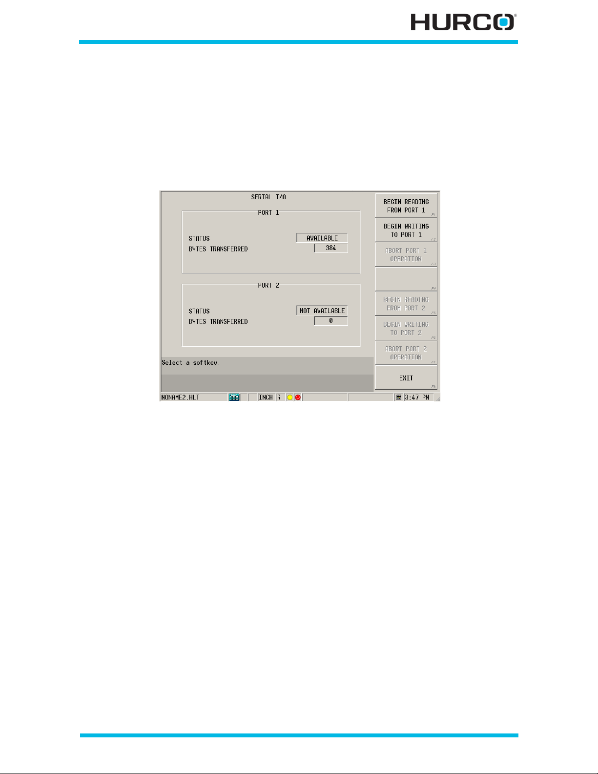
Serial I/O
Press the Aux/Menu key fo llowed by the Utility Screen softkey to access the Utilities
screen and softkey menu. From the Utilities screen, select the MORE F7 softkey
followed by the SERIAL I/O F1 softkey to access the Serial I/O screen. Two serial ports
are available on the control. The Serial I/O screen contains Status and Bytes Transferred
fields for both ports. In addition, there are read, write, and abo rt softkeys for both ports.
Figure 2–22. Serial I/O screen
These fields appear on the Serial I/O screen:
• STATUS—displays status for this port as Available or Not Available.
• BYTES TRANSFERRED—indicates the number of bytes transferred for this
port.
These so ftkeys are av ailable on th e Serial I/O screen . Duplicate se ts of field s and softkeys
are available on the Serial I/O screen for Port 1 and Port 2.
• BEGIN READIN G F ROM PORT 1 F1—brings up 2 softkey choices: READ NC
FROM PORT and READ CONV FROM PORT to identify the program format to
read.
• BEGIN WRITING TO PORT1 F2—writes the program to the port.
• ABORT PORT OPE RATION F3—halts the read or write operation for the
port.
Getting Started—WinMax Lathe Max Control v546GS Utilities 2-27
Page 80

Log Files
Press the Menu key fol lowed by the Utility Screen softkey to access the Utilities screen
and softkey menu. From the Utilities screen, select the MORE F7 softkey followed by
the LOG FILES F2 softkey to access the Log Files screen. As the turning center runs, it
generates three types of text prompts: Notification, Error, and Status. The Error and
Status messages can be viewed in log files.
To manually produce a text file containing control re gisters for a
particular moment in time, se lect the ALT +0 (zero) console keys.
These files are also created by the control automatically under
certain circumstances.
The control places the files into the Significant Events location
described below. Example file name:
20111107 100403.shmDmp.txt
The filename represents the exact moment the file was cr eated:
[DATE]20111107+[TIME]100403.shmDmp.txt.
Accessin g Log Files
Select the LOG FILES F7 softkey to access these log file selections.
• AC TIVE ERROR LISTING F1—displays a list of errors still in effect in the
Active Error Listing screen. This list includes a date, time, filename and
description for each error. PREVIOUS PAGE F1 and NEXT PAGE F2 softkeys
become available for accessing multiple page lists. A CLEAR ALL F4 softkey
clears the list.
• AC TIVE STATUS LISTING F2—displays a list of status messages still in
effect in the Active Status Listing screen. Status messages relay information
about the machine. PREVIOUS PA GE F1 and NEXT PAGE F2 softkeys become
available for accessing multiple page lists. A CLEAR ALL F4 softkey clears the
list.
• ERROR HISTORY F3—displays the last 50 error messages in the Error
History screen. This list includes a date, time, filename and description for
each error. PREVI OUS PAGE F1 an d NEXT PAGE F2 s oftkeys becom e available
for accessing multiple page lists. A CLEAR ALL F4 softkey clears the list.
• STATUS HISTORY F4—displays the last 50 status messages in the Status
History screen. This list includes a date, time, filename and description for
each status message. PREVIOUS PAGE F1 and NEXT PAGE F2 softkeys
become available for accessing multiple page lists. A CLEAR ALL F4 softkey
clears the list.
2 - 28 Utilities v546GS Getting Started—WinMax Lathe Max Control
Page 81
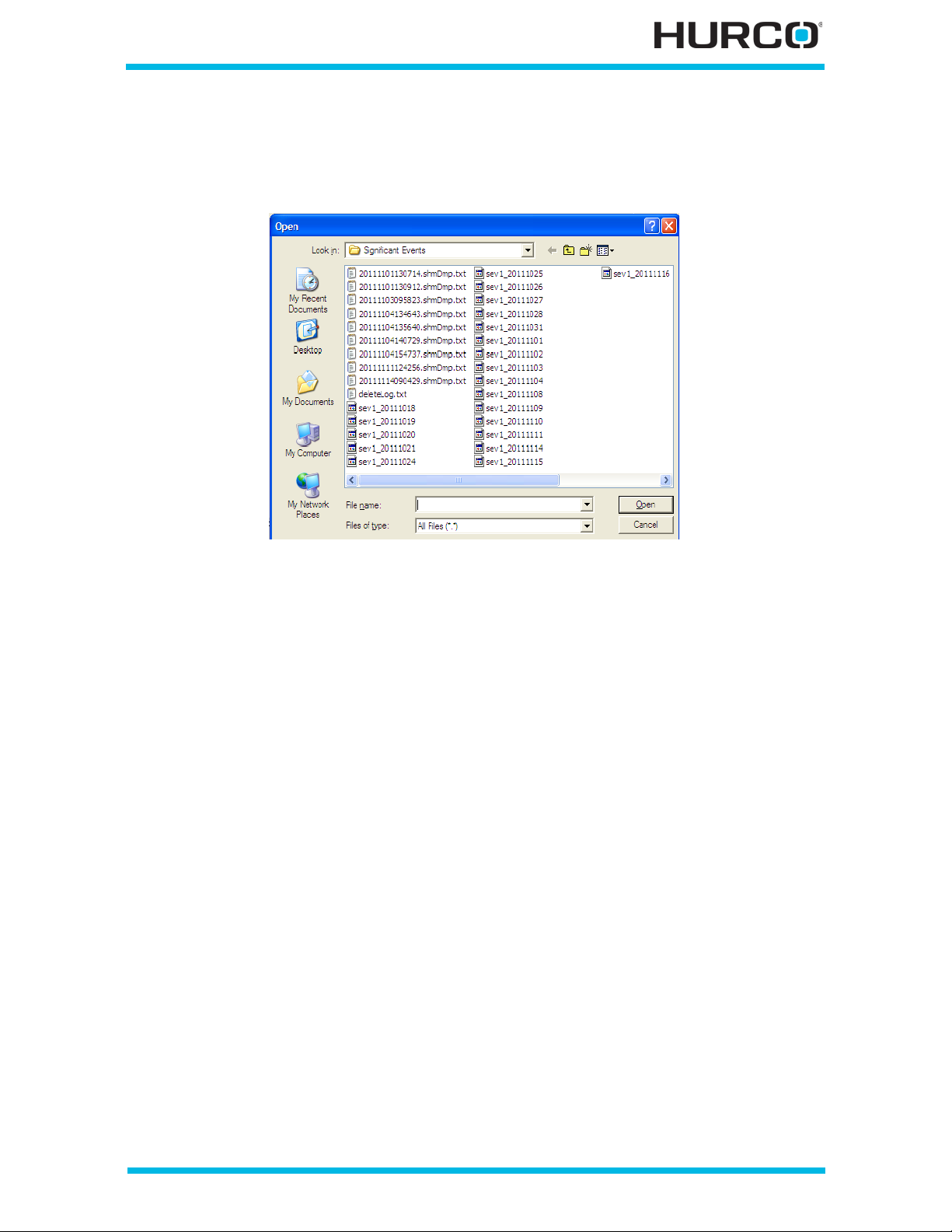
• VIEW EVENT LOG FILE F7—accesses the folder on the control containing
the Significant Event files in an Open pop-up window. The example below
shows Significant Event files (for example, “sev1_20111118”) and control
register files (for example, 201111101130714.shmDmp.txt”
Figure 2–23. Open pop-up window for Significant Events files
Retrieving Log Files
When it is necessary to copy certain files for service purposes, follow these steps:
1. Insert a USB flash memory device to the external connector on the
communications port on the machin e.
2. From the Input screen select the Project Manager F8 softkey. The Project
Manager screen opens.
3. Select the File Manager F7 softkey. Directories containing system files are
located in the left-hand pane. The Log files reside in the Part Programs (D)
directory.
4. Naviga te to the Significant Events folder following this path:
Part Programs (D)/Hurco/WinMax/Output Files/Significant Events
5. Select the file(s) you wish to copy from the right-hand pane.
6. Select the Copy File(s) F2 softkey.
7. In the left-hand pane, select the USB flash memory device (will probably
indicate it is E drive in parentheses).
8. Select the Past e File(s) F3 softkey. The fi les are now on the USB flash memory
device, and can be transferred to a PC to be emailed.
Getting Started—WinMax Lathe Max Control v546GS Utilities 2-29
Page 82

2 - 30 Utilities v546GS Getting Started—WinMax Lathe Max Control
Page 83

PROJECT MANAGER
This section explains how to create and manage files and directories, set program
properties, use File Manager, and access the UltiMonitor option using FTP Manager. Refer
to WinMax Lathe Options UltiMonitor, on page 17 - 1 for details about UltiNet. The
following topics are explained in this section:
Overview. . . . . . . . . . . . . . . . . . . . . . . . . . . . . . . . . . . . . . . . . . . . . . . . . 3 - 2
Managing Program Files . . . . . . . . . . . . . . . . . . . . . . . . . . . . . . . . . . . . . . 3 - 3
Set Program Properties . . . . . . . . . . . . . . . . . . . . . . . . . . . . . . . . . . . . . . . 3 - 6
Use File Manager . . . . . . . . . . . . . . . . . . . . . . . . . . . . . . . . . . . . . . . . . . . 3 - 7
Use the FTP Manager . . . . . . . . . . . . . . . . . . . . . . . . . . . . . . . . . . . . . . . . 3 - 9
Getting Started—WinMax Lathe Max Control v546GS Project Manager 3-1
Page 84
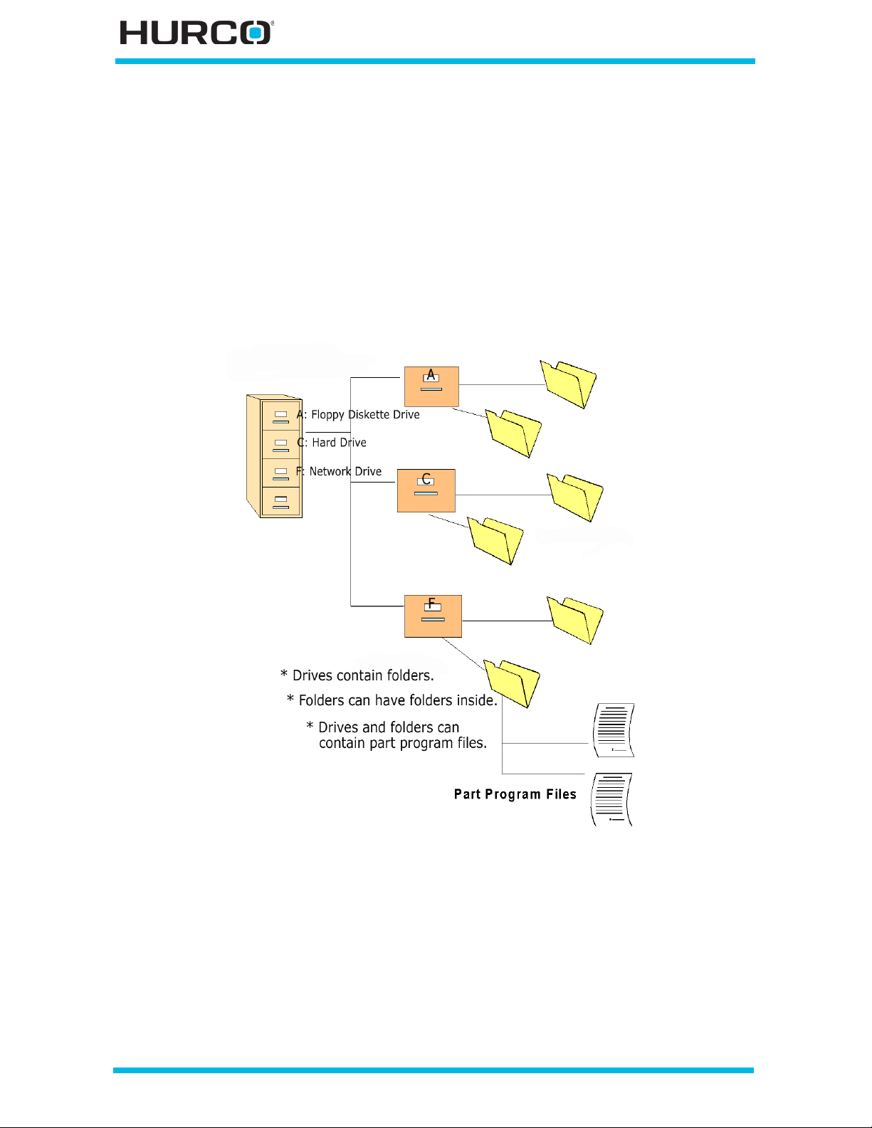
Overview
Part programs are stored on the Computer Numeric Control (CNC) hard drive, network
drive, or on removable USB devices. Each drive contains one main directory—the root
directory. An operator cannot create this directory, but folders and sub-folders can be
stored in it or in other drives, such as floppy drives or network drives.
Compare file management to a filing cabinet. The drives are like drawers in the filing
cabinet. Subdirectories are the folders inside a drawer, or a drive. Folders and files are
stored in the cabinet drawers. Part programs are like i ndividual sheets of paper that are
store d loosely on the drives or inside folders.
Figure 3–1. Directory Structure
3 - 2 Project Manager v546GS Getting Started—WinMax Lathe Max Control
Page 85
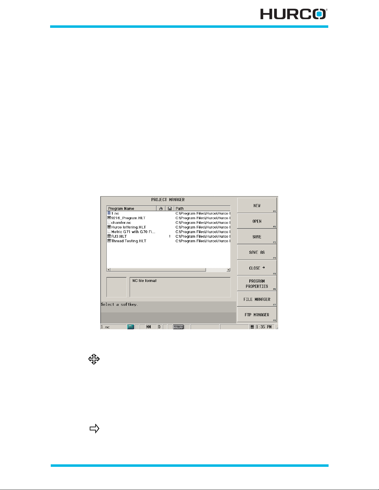
Managing Program Files
Project Manager shows all part programs that are in the control’s memory to edit or run.
Use the Program Manager menu to create, open, sa ve, and close programs. Features of
the Program Manager include:
• Ability to load more than one program at a time.
• Ability to load Conversational and NC programs at the same time.
• Ability to copy blocks from one program into another (blocks are copied in
Progra m Review; Program Manager i s used to switch between programs to
facilitate copy and paste).
• A snapshot of the program.
Either press the Aux/Menu key or the Input key followed by the PROJECT MANAGER
F8 softkey to access the Project Manager screen and softkey menu. You can also use the
menu toolbar and se lect the Project Mana ger icon to access this screen.
Figure 3–2. Project Manager screen
For detailed information about NC programming, refer to WinMax
Lathe NC Programming Overview, on page 1 - 1
A lock icon appears between the program name and path name when the file is in use on
a network. When this icon is visible, the file cannot be edited, saved, or closed.
An “!” (exclamation mark) appears between the program name and path name when the
file has been modified and not saved. Save the file to keep changes.
More than one program can be loaded in memory at a time.
However, only the program that is highlighted will be the active
program for editing, graphing, and running.
Getting Started—WinMax Lathe Max Control v546GS Project Manager 3-3
Page 86

Create a New File
Either press the Menu key or the Input key followed by the PROJECT MANAER F8
softkey to access the Project Manager screen and softkey menu. You can also use the
menu toolbar and se lect the Project Mana ger icon to access this screen.
Select the NE W F1 softkey to create a blank part program. Choose the file type by
selecting one of these softkeys:
• CREATE HLT PROGRAM F1—creates a new conversational part program
named NONAME1.HLT.
• CREATE NC P ROGRAM F2—creates a new NC part program named
NONAME1.LNC.
Use the Save As feature to change the name from the default
NONAME1.HLT or NONAME1.LNC to avoid saving one file over
another. Refer to Save Files, on page 3 - 5 for details.
Open a File
Select the OPEN F2 softkey to open a previously saved part program. The Load Program
screen displays a list of drives and folders for locating existing programs.
1. Select a folder and the files within the folder appear on the right-hand side.
2. Highlight the file to open.
3. Select the LOAD SELECTED FILE(S) F1 softkey.
The Load Program screen allows you to sort the file list by File,
Size, or Date. To sort the list by any of these criteria , simply use
the stylus and tap the appropriate header.
If you sort by one header and then by another, the file list will sort
first by the most recent header selected then by the previous
selection. For example, selecting File then Date will sort the file
list in ascending order by Date. If any files have the same date
listed, they will be sorted alphabetically by file name within eac h
date.
Selecting a heading a second time inverts the order. For example,
the alphabetical order for files sorted from A to Z will be sorted
from Z to A with the second click of the heading.
3 - 4 Project Manager v546GS Getting Started—WinMax Lathe Max Control
Page 87
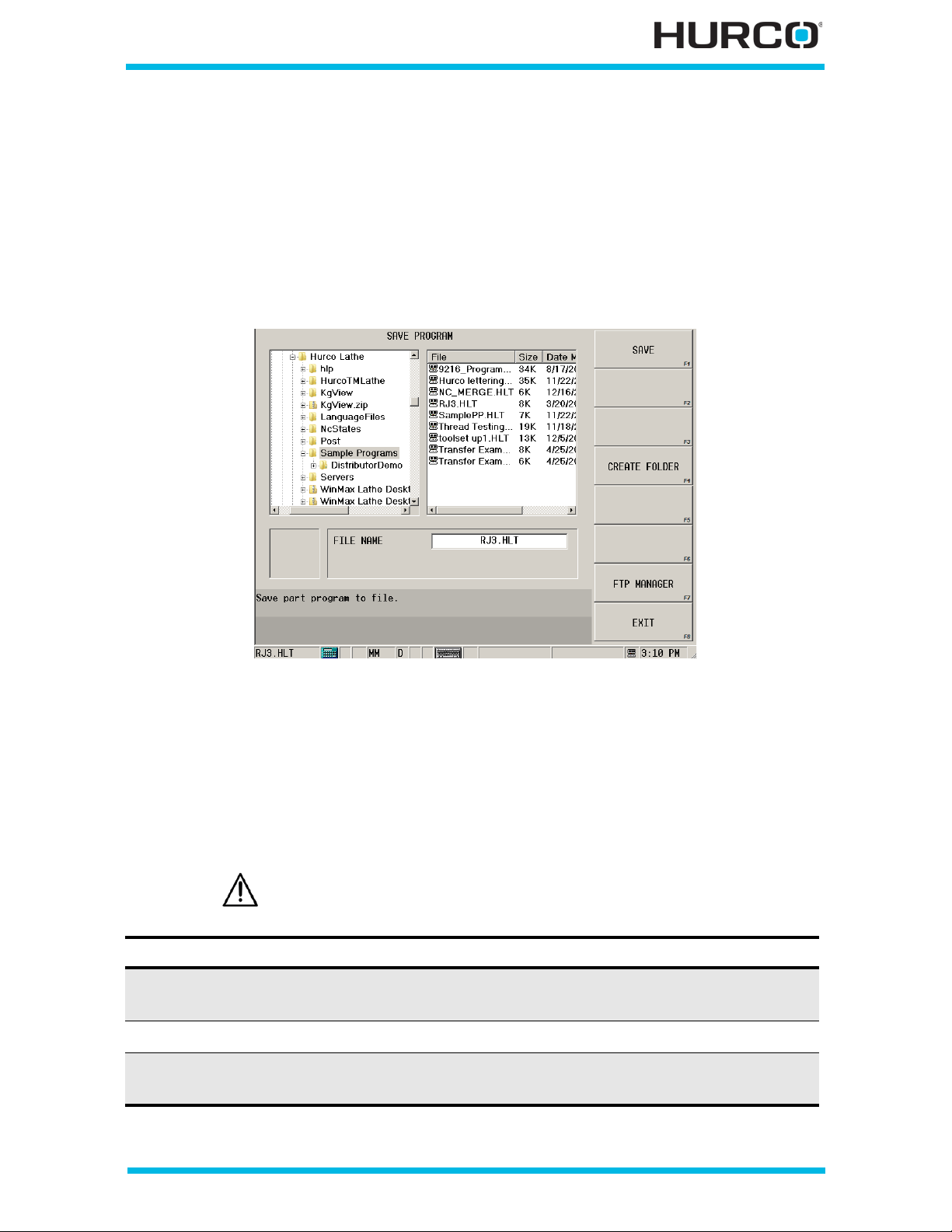
Save Files
Select the SAVE F3 softkey to save the current part program onto a drive to which you
have access. Select the SAV E AS F4 softkey to create a file by saving the current part
program under a different name, as a different file type, or in a different location.
The Save Prog ram screen appears. The left-hand pane sh ows the drives and folders.
When you select a folder, the files stored in the folder appear in the right-hand pane. The
file’s size and date it was saved appear next to the file name.
Figure 3–3. List of System Directories and File Names—Saving a File
If the prog ram nam e is the default NONAME1 or if you want to save a file with a different
name , select the SAVE AS F4 softkey and the screen reverts to the list of drives and
folders. The list opens in the same location as the current program with NONAME1.HLT in
the FILE NAME field.
If th e pr ogr a m w as pr e vio u sl y s a ve d, y ou can selec t SA V E F1 and the program will save in
the same drive, directory, and filename.
Creating a New Folder for Storing A File: Saving the File in a Different Folder:
1. Highlight the folder where the new
folder will reside.
2. Select CREATE FOLDER F4. 2. Enter a file name.
3. Enter the folder name in the pop-up
window and select OK.
Change the name from the default NONAME1.HLT to avoid saving
one file over another.
1. Highlight the appropriate folder.
3. Select SAV E F1.
Getting Started—WinMax Lathe Max Control v546GS Project Manager 3-5
Page 88

Close a File
Press the Menu key to access the Project Manager screen and softkey menu. Select the
CLOSE F5 softkey to remove a program or programs from the file listing. Multiple
programs can be open (in memory) at one time. Having too many programs open can
affect system performance. Close files to free up internal memory used for editing,
graphing, and running programs.
Select CLOSE ALL PROGRAMS F3 or CLOSE SELECTED PROGRAM F5. If only one
program is listed, then either softkey c an be used. If more than one program is listed,
then be sure to select the appropriate softkey.
Make note of the “!” (exclamation mark) status as closing a program that has not been
saved will lose all changes made since the last time it was saved. If modifications have
been made to a program that has not been saved, a prompt appears before closing.
• Select OK to continue the close operation without saving.
• Select Cancel to cancel the operation.
Set Prog ram Prope r ti es
Select the P ROGRAM PROPERTIES F6 softkey to change and store properties for the
selected file. The settings originate from the Utilities screen, User Preferences,
Conversati onal Setti ngs screen. Ref er to Con versational Setting s, on pag e 2 - 16 for more
informa tion about the settings. You can override the defaults for a program using
Program Properties.
These fields appear when this softkey is selected:
• DIS PLAY UNITS—enter Inc hes or Millimeters for the un it of measurement
used throughout the part programming for HLT files. This field does not apply
to NC programs.
• PROGRAMMING MODE—enter Radius or Diameter for the programming
mode. This field does not apply to NC programs.
• DESCRIPTION—enter a text description of the selected file. You can enter
up to 47 characters on each of two lines. This text appears at the bottom of
the Project Manager screen when the file is highlighted.
• WRIT E PR O TEC TION —select ON to provide write protection for the current
program. This selection prevents changes to the program from being saved.
Select OFF to remove write protection and allow editing of the program.
These fields are displayed but cannot be chang ed on this screen:
• NAME—displays the file name of the program. This field is read-only. To
change the name of the saved file, select the Exit key followed by the SAVE
AS softkey.
• PATH—displays the path to the saved file. This field is read-onl y. To change
the path for the saved file, select the EXIT F8 softkey followed by the SAVE
AS F4 softkey.
3 - 6 Project Manager v546GS Getting Started—WinMax Lathe Max Control
Page 89

Us e File Manager
From the Project Manager screen, select the FILE MANAGER F7 softkey to perform file
mana ge me nt func ti o ns, s uch a s re nam ing a fo lder o r fi le nam e, or del et ing file s o r fold er s
from the drive.
The control detects when a USB drive is inserted or removed and
updates the File Manager Direc tory. When the USB drive is detected,
files can be loaded from and saved to the USB drive.
Folders
When a folder is highlighted in the left-hand pane, the softkey menu displays folder
management options.
• CUT FOLDER F1—removes the selected folder from its current location and
places it on a “clipboard.” You may then paste the folder in another location.
Make sure you do not cut or copy another folder before pasting the folder in
its new location. The clipboard contains only the most recently cut or copied
folder. Cutting a folder also cuts all files and fold ers contained with the folder.
• COPY FOLD ER F2—places a copy of the selected folder on a “clipboard.”
Once a folder has been placed on the clipboard, you may paste it in a new
location. The cl ipboard contains only the most recently cut or copie d fold er.
Copying a folder also copies all files and folders contained within the folder.
• PASTE FILE (S) INT O FO LDER F3—places a copy of the most recently cut or
copied file(s) or folder to the “clipboard” in the selected location. The file(s)
or folder will remain on the clipboard and can be pasted elsewhere until
another file or folder is cut or copied to the clipboard. Pasting a folder also
pastes all files and folders contained within the folder.
• CREATE FOLDER F4—creates a new folder in the selected location. The
control prompts you to ent er a name for the new folder when you select this
softkey. Enter the name that you wish to use for the new folder and click OK.
• RE NAME FOLDER F5—allows you to rename the selected folder. When you
select this softkey, a pop-up window appears prompting you to “Enter new
file name.” En ter the nam e for the folde r and select OK. Sel ect Cancel to keep
the same folder name.
• DELETE F OLDE R F6—deletes the selected folder along with any folders or
files contain ed within the folder. This will not place a copy of the folder on the
clipboard and you will not be able to retrieve a folder once it has been
deleted. Use extreme caution when using this softkey. A message appears
when you se lect it asking “Continue with delete operation?” If you are sure
that you want to delete the folder, select OK. If you do not wish to delete the
folder, select Cancel.
Getting Started—WinMax Lathe Max Control v546GS Project Manager 3-7
Page 90

Files
When a file name is highlighted in the right-hand pane, the softkey menu provides file
management options.
• CUT FILE(S) F1—removes the selected file from its current location and
places it on a “clipboard.” You may then paste the file in another location.
Make sure you do not cut or copy another file before pasting the file in its
new location. THe clipboard contains only the most recently cut or copied file.
• COPY FILE( S) F2— p l ace s a co p y o f th e sel e ct ed f i le on t he “ c li pb o ard . ” Onc e
a file has been placed on the clipboard, you may paste it in a n ew location.
The clipboard contains only the most recently cut or copied file.
• PASTE FILE(S ) F3—places a copy of the last file that was cut or copied to
the “clipboard” in the selected location. The file will remain on the clipboard
afte r pasting and can be pasted elsewhere until another file is cut or copied to
the clipboard.
• RE NAME FILE(S) F4—allows you to rename the selected file. When you
select this softkey, a pop-up window appears asking you to “Enter new file
na me.” Enter the name you want to name the file and select OK. Select
Cancel to keep the file name.
• DELE TE FILE(S ) F5—deletes the selected file. This will not place a copy of
the file on the clipboard and you will not be able to retrieve a file once it has
been deleted. Use extreme caution when using the Delete File(s) softkey. A
message appears when you select this softkey asking “Continue with delete
operation?” If you are sure that you want to delete the file, select OK. If you
do not wish to delete the file, select Cancel.
• LOAD SE LECTED FILE F6—loads the selected file into memory (this
selection opens the file just as it does with the Project Manager/Open menu.
Other Softkeys
These softkeys appear on the File Manager screen whether a filename is highlighted or a
folder is highlighted:
• FTP MANAGER F7—acce s se s th e FT P Ma nag e r so ft key menu . O n the Proj e ct
Manager screen, the FTP MANAGER softkey is F8. Refer to WinMax Lathe
Options for details about the UltiMonitor option.
• EXIT F8—returns to the Project Manager screen
3 - 8 Project Manager v546GS Getting Started—WinMax Lathe Max Control
Page 91
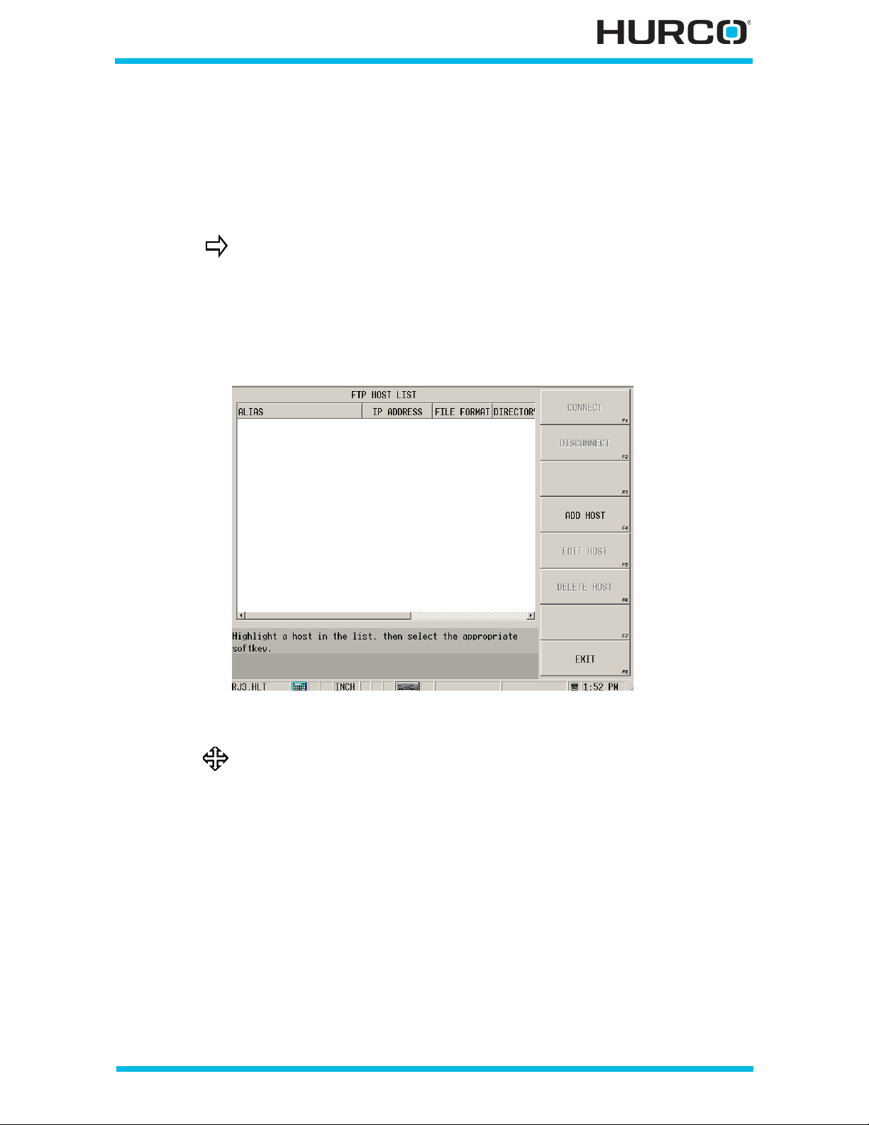
Use the F TP Manager
FTP (File Transfer Protocol) is a method of transferring fil es from one computer to another
using the Internet and access the UltiMonitor option. Refer to WinMax Lathe Options
UltiMonitor, on page 17 - 1 for details about UltiNet.
Customers using UltiNet should refer to the UltiMonitor section for
product guidance.
Press the Menu key to access the Project Manager screen and softkey menu. The FTP
MANAGER F8 softkey accesses the FTP Host List screen. The FTP MANAGER F7 softkey
on the File Manager screen also accesses this same screen. From here, you can connect
to or disconnect from, add, edit, and delete FTP servers which are identified on this list.
Figure 3–4. FTP Host List screen
Refer to WinMax Lathe Options UltiMonitor, on page 17 - 1 for
information ab out setting up the FTP server.
Getting Started—WinMax Lathe Max Control v546GS Project Manager 3-9
Page 92

3 - 10 Project Manager v546GS Getting Started—WinMax Lathe Max Control
Page 93

PROGRAMMING BASICS
This section explains basic programming information for Conver sational and NC
programming, such as required setup and program checking.
Part Programming . . . . . . . . . . . . . . . . . . . . . . . . . . . . . . . . . . . . . . . . . . 4 - 2
Part and Tool Loading . . . . . . . . . . . . . . . . . . . . . . . . . . . . . . . . . . . . . . . . 4 - 7
Part Setup—Work Offsets . . . . . . . . . . . . . . . . . . . . . . . . . . . . . . . . . . . . . 4 - 11
Tool Setup—Geometry Offsets . . . . . . . . . . . . . . . . . . . . . . . . . . . . . . . . . . 4 - 17
Tool Rev iew . . . . . . . . . . . . . . . . . . . . . . . . . . . . . . . . . . . . . . . . . . . . . . . 4 - 77
Program Parameters. . . . . . . . . . . . . . . . . . . . . . . . . . . . . . . . . . . . . . . . . 4 - 82
Verifying Part Programs—Graphics . . . . . . . . . . . . . . . . . . . . . . . . . . . . . . . 4 - 86
Programming Training. . . . . . . . . . . . . . . . . . . . . . . . . . . . . . . . . . . . . . . . 4 - 91
Getting Started—WinMax Lathe Max Control v546GS Programming Basics 4-1
Page 94
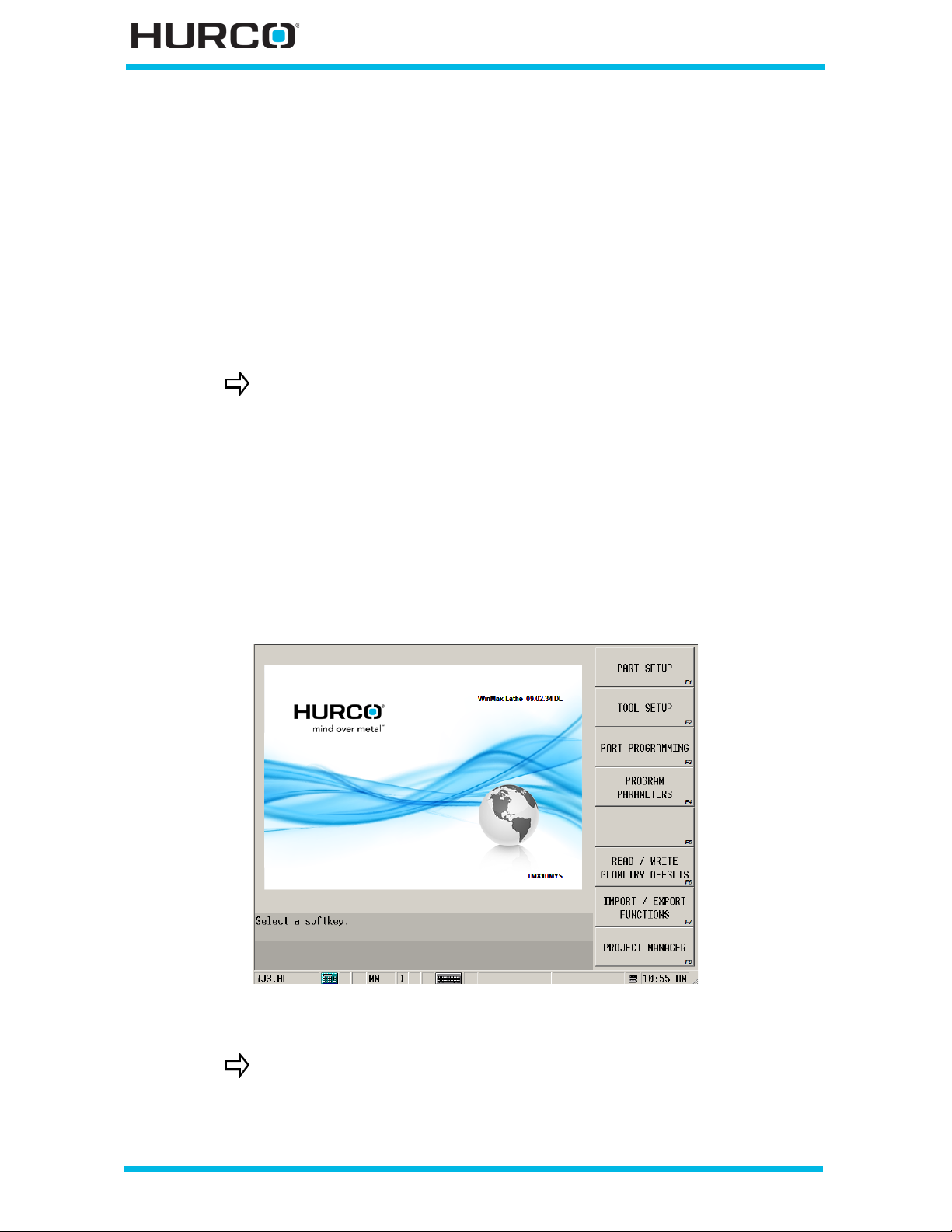
Part Programming
There are five main steps to follow before creating a part program on the control:
1. Plan t he part programming operations.
2. Perform the tool- and part-loading operations. Refer to Part and Tool Loading,
on page 4 - 7.
3. Enter the Part Setup information. Refer to Part Setup—Work Offsets, on page
4 - 11.
4. Enter the T ool Setup information. Ref e r to Tool Setup—Geometry Offsets, on
page 4 - 17.
The Read/Write Geometry Offsets softkey accesses a menu that
functions the same as the menu described in Tool Geometry Offsets,
on page 4 - 67.
5. Enter the Program Parameters information. Refer to Program Parameters, on
page 4 - 82.
The remaining softkeys are available for NC programming. Please refer to WinMax Lathe
NC Programing Overview, on page 1 - 1, Importing and Exporting M Code Data, on page
1 - 29, M Code Trans lation, on page 5 - 2, and WinMax Lathe Options, NCPP Variab l es, on
page 8 - 2 for information about their functions.
The Input screen contains softkeys for accessing menus for the programming tasks.
Figure 4–1. Input Screen
Fields or softkeys appear grayed out and are not accessible when
lockout mode is enabled.
4 - 2 Programmi ng Basics v546GS Getting Started—WinMax Lathe Max Control
Page 95
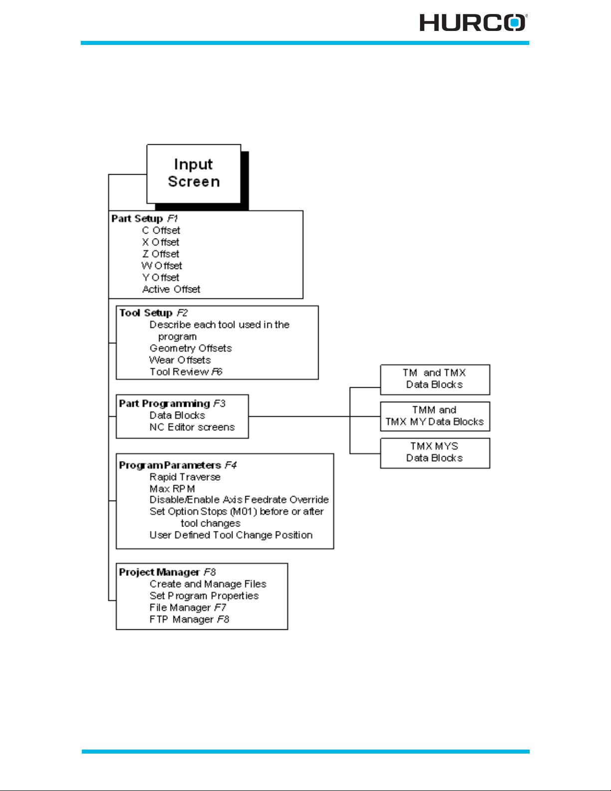
The following diagram shows how the software is set up, starting with the Input screen,
accessing Part Setup F1, Tool Setup F2, Part Programming F3 for programming Data
blocks, Program Parameters F4, and Project Manager F8.
Figure 4–2. WinMax Lathe Programming diagram
Getting Started—WinMax Lathe Max Control v546GS Programming Basics 4-3
Page 96

The following table identifies the types of data blocks that can be programmed from the
Part Programming F3 softkey menu for each turning center machine type:
Data Blo cks
Position F1
Turning
F2
Profile F1
Thread F2
Groove F3
Hole F4
Cutoff F5
Exit F8 to New Block screen
Liv e Tooling F3
(TMM, TMX MY, and TMX MYS machines only)
Radial Milling F1
Radial Holes F2
Axial Milling F4
Axial Holes F5
Exit F8 to New Block screen
Miscellaneous F4
Change Parameters F1
Change Part Setup F2
M Code F3
Bar Feed F4
Comment F5
NC Program Call F6
More
F7
Repeat Start F1
Repea t End F2
More F7
Exit F8 to New Block screen
Transfer F5
(TMX MYS ma chines only)
Move Ta ilstock F5
(TM12 and TM18 machines only)
Exit F8 to Input Screen
Table 4–1. Types of Data Blocks
4 - 4 Programmi ng Basics v546GS Getting Started—WinMax Lathe Max Control
Page 97
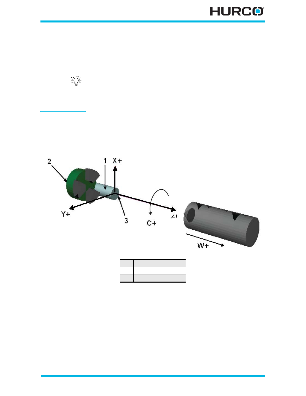
Planning
Before your begin programming, decide what mate rial and tools are needed. It is
important to be familiar with the axes motion on the machine and how to obtain the
information required for the setup screens. These topics are described i n this section.
Save your program with a unique , correct name before pr oceeding.
Following this practice can help avoid accidentally deleting a file
because of a generic filename. Refer to Save Files, on page 3 - 5 for
details about saving files.
Axes Movement
Be familiar with the axis movement in preparation for programming. This diagram
identifies positive (+) axis movement (and alternatively negative (-) axis movement),
showing axes for all turning cente r configurations.
1 Workpiece
2 Machine Zero
3 Par t O ffset
Figure 4–3. Turning Center Axes Motion
Radial and axial tools are used for live tooling.
• Radial tooling approaches the stock in the -X axis direction.
• Axial tooling approaches the stock in the -Z axis direction.
Getting Started—WinMax Lathe Max Control v546GS Programming Basics 4-5
Page 98
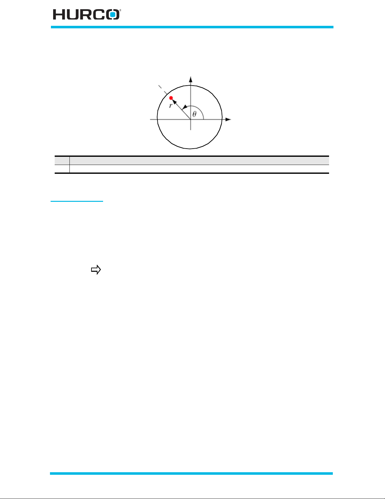
This diagram identifies the radial and angular polar coordinates for live-tooling turning
centers.
r The radial coordinate (the radial distance from the center).
q The angular coordinate, or the polar angle (counterclockwise angle from the X-axis).
Figure 4–4. Live-Tooling Turning Center Polar Coordinate Axes Motion
Setup Screens
The part and tool setup screens describe the part and the tools used to cut the part. This
information is necessary for the system to draw the part.
To perform many of the setup functions, use the axis controls to move the turret and
record positions. Refer to Axis and Spindle Control, on page 1 - 16 for information about
axis con trols.
Part and Tool Setup information is saved with conversational
programs but not with NC programs.
4 - 6 Programmi ng Basics v546GS Getting Started—WinMax Lathe Max Control
Page 99
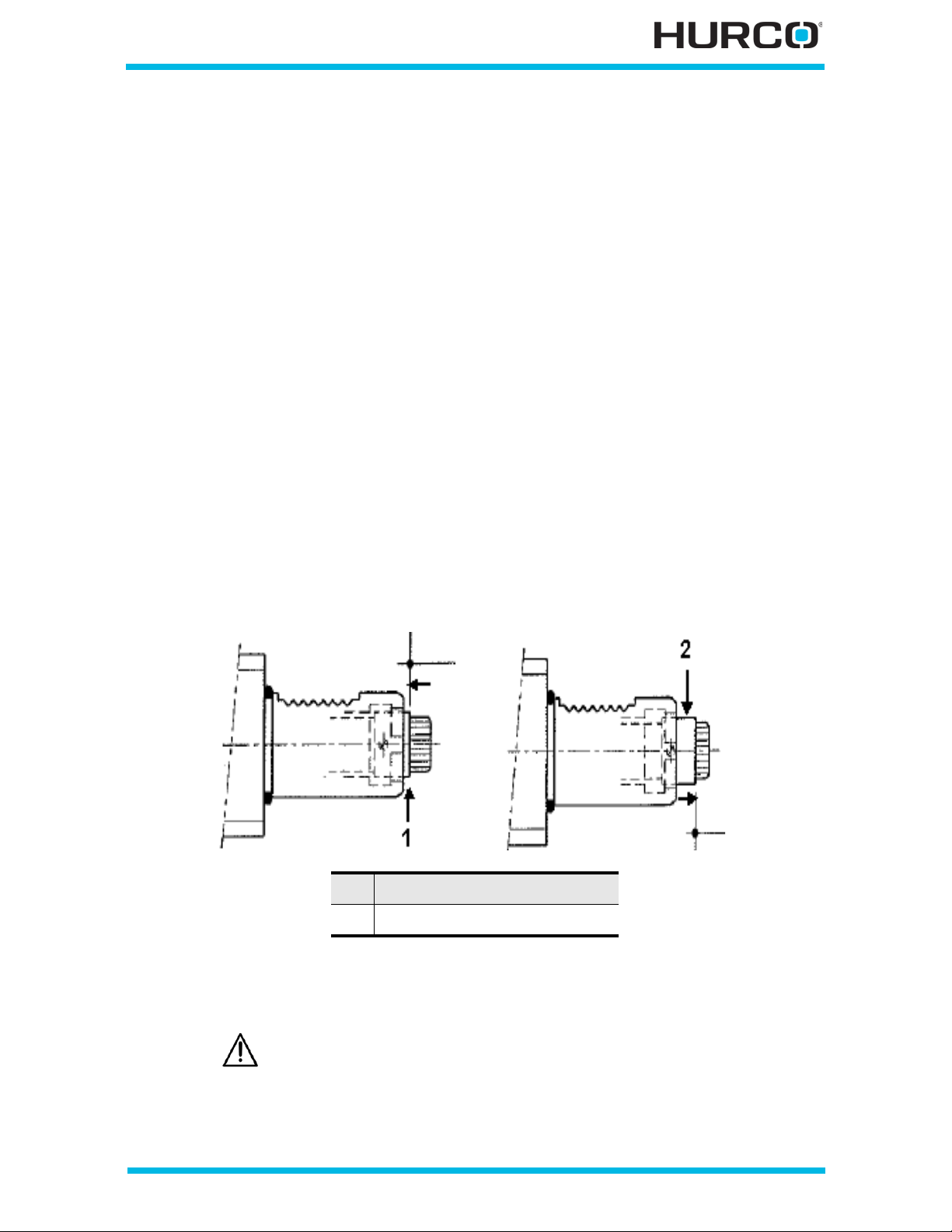
Part and Tool Loading
This section describes loading the workpiece an d the tools in preparation for
programming the Part and Tool Setup screens.
Loading the Workpiece
In order to determine the reference poin t (part zero) in the part, first load the work piece
(raw material or stock) into the chuck or optional collet. Refer to the Maintenance and
Safety manual for information about hydraulic settings for the optional collet. Refer to
Chuck Operations, on page 5 - 48 for information about operating the chuck.
Loading Live Tooling Tool Holders
Hurco TMM, TMX MY, and TMX MYS Series turning centers use tool holders mounted in
turret turning stations to hold tools. Each tool holder must be inserted into the turret.
To insert the tool holder into the turret,
1. Index the turret forward or backward one station. Refer to Load Tools in Turret
and Assign Tool Numbers, on page 4 - 9 for directions for indexing the turret.
2. Turn the splineshaft for the tool holder until the notch fits into the detent and
the collar slides out. The following figures first show the collar in its unlocked
position (1) and second in its locked p osition (2).
1 Unlocked position
2 Locked position
Figure 4–5. Live Tooling Tool Holder Collar
3. Follow the directions in the Load Tools in Turret and Assign Tool Numbers, on
page 4 - 9 to mount the live tool holder in a non Active Tool Index location.
Before using a live to ol, check these items:
• the sealing rings are present and not damaged.
• the coupling profile is clean and not damaged.
• the spindle locking mechanism is engaged.
Getting Started—WinMax Lathe Max Control v546GS Programming Basics 4-7
Page 100

Loading Tools
Hurco turning centers use a turret to hold tools. Each tool is manually inserted into the
turret. There are multiple turning center configurations:
•Two Axis (TM series)
• Live Tooling (TMM series)
• Two Axis with Programmable Tailstock (TMX series)
• Live Tooling with Y-Axis Motion (TMX MY series)
• Live Tooling with Y-Axis Motion and Sub-spindle (TMX MYS series).
Tools in the turret are described and programmed during Tool Setup. Refer to Tool
Setup—Geometry Offsets, on page 4 - 17 for programming information.
Two Axis (TM and TMX seri es)
• The turret contains boring blocks for holding tools and turning stations for
holding turning tools.
• Bolts secure tools inserted in boring blocks; wedge clamps secure tools in
their stations.
Live Tooling (TMM , TMXMY, and TM X M Y S series)
• Tool holders are inserted and locked in place with VDI set screws.
• Static holders are us ed for turning and boring tools.
• Live tools use collet holders.
All se ries
• Turret stations are numbered to identify and locate each too l.
• Use the Turret Plus (+) or Minus (-) console keys to increment or decrement
the tool station.
4 - 8 Programmi ng Basics v546GS Getting Started—WinMax Lathe Max Control
 Loading...