

Page 1

704-0101-761
Autobend 6
Installation Manual
Revision E
November, 1999
Installation Manual
Autobend 6
This manual pertains to the Autobend Control System:
(Record Serial Number here)
Hurco Companies, Inc. reserves the right to incorporate any modifications
or improvements in machines and machine specifications which it
considers necessary, and does not assume any obligation to make any said
changes in machines or equipment previously sold.
Hurco products and services are subject to Hurco’s then current prices,
terms, and conditions, which are subject to change without notice.
Page 2

The information in this document is subject to change without notice and does not
represent a commitment on the part of Hurco Companies, Inc. (Hurco). No part of this
document may be reproduced or transmitted in any form or by any means, electronic or
mechanical, including photocopying, for any purpose without the express written
permission of Hurco.
1999 Hurco Companies, Inc. All rights reserved. Printed in the United States of America.
Amada is a registered trademark of Amada Co. Ltd.
Hurco and Autobend are registered trademarks of Hurco Companies, Inc.
Guifil is a registered trademark of Guimaraes and Filho, Lba.
IBM and PC/AT are registered trademarks of International Business Machines Corporation.
Komatsu is a registered trademark of Komatsu Ltd.
Many of the designations used by manufacturers and sellers to distinguish their products
are claimed as trademarks. Hurco has listed here all trademarks of which it is aware.
Patents:
U.S. Patents B14,477,754; 5,453,933; Canadian Patent 1,102,434; Japanese
Patents 1,649,006 and 1,375,124; other Patents pending.
For more information on Hurco products and services, contact the corporate headquarters
in Indianapolis, Indiana or one of the subsidiaries listed below:
Hurco Companies, Inc. Autocon Technologies, Inc. Hurco Southeast Asia Pte Ltd
One Technology Way
P.O. Box 68180
Indianapolis, Indiana
46268-0180
TEL (317) 293-5309 TEL (248) 488-0440 TEL (65) 742 6177
FAX (317) 328-2812 FAX (248) 488-0430 FAX (65) 745 7664
Autobend Service
TEL (317) 298-2639
FAX (317) 328-2806
Hurco Europe Ltd. Hurco s.a.r.l. Hurco GmbH
Lincoln Road
Cressex Industrial Estates
High Wycombe
Buckinghamshire, England
HP12 3TH
TEL (01494) 442222 TEL (1) 39.88.64.00 TEL (089) 9050 9434
FAX (01494) 444646 FAX (1) 39.92.94.83 FAX (089) 9050 9450
38455 Hills Tech Drive
Farmington Hills, Michigan
48331-5751
Centre Hurco
Belgique, Espagne, France, Portugal
Parc d’activité Charles de Gaulle
4, rue Jean Monnet - BP 702
95197 Goussainville Cedex France
No. 37 Lorong 23 Geylang
#0501, Yu Li Industrial Building
Singapore 1438
Republic of Singapore
Benzstrasse 8
85551 Kirchheim
Munich, Germany
Autobend 6 November, 1999 iii
Page 3

iv Revision E Hurco
Page 4

Hurco is committed to designing reliable, easy-to-operate machines which
promote greater productivity. This system will provide a modern, efficient
method of meeting metal forming needs. To prevent serious bodily injury,
always observe the safety precautions listed in this manual when installing,
operating, and servicing the Autobend System.
These and other safety precautions are discussed in the American National
Standards Institute’s “Standard for Machine Tools - Power Press Brakes Safety Requirements for Construction, Care, and Use” (ANSI B11.3). The
press brake operator’s responsibility regarding his or her own safety, the
safety of assigned helpers, and the safety of others affected by the press
brake operator’s acts is explained in this ANSI publication which is
available from:
American National Standards Institute
1430 Broadway
New York, NY 10018
In preparing these instructions, we have attempted to recommend the most
effective methods and cautions to warn against actions that could cause
personal injury or make the equipment unsafe. It is important to
understand that Hurco cannot anticipate or list all conceivable methods
and warn of all possible hazards. In the interest of promoting safety, Hurco
advises that service personnel and operators should always make sure that
personal safety, the safety of the operator, and the safe operation of the
machine will not be adversely affected by their actions. Review the list of
safety precautions before attempting to service or operate the system. Also
review the manuals furnished by your press brake manufacturer for
additional safety information and procedures that must be observed.
Please read all information for safe, efficient use of the Hurco Autobend 6
Control System.
Autobend 6 November, 1999 v
Page 5

vi Revision E Hurco
Page 6

Using this Manual
The
Installation Manual
service representatives for installing the Autobend 6 control system. This
manual employs several conventions to explain the system concepts and
point out key concepts. These conventions are described in this section.
is intended to be used by customers and Hurco
Sections of the Manual
This manual is divided into these chapters:
Chapter 1 - Introduction
Chapter 2 - Installation
Chapter 3 - Maintenance
Follow the checklist at the end of the “Installation” chapter while
installing and referencing the system. Refer to the “Installation” chapter
for detailed information.
There is also an index that cross-references the material presented in the
manual.
Style Guide
Indexed terms are
Titles of books also appear in italic print to meet the English language
convention for titles. References to chapter and section names within the
text are set in quotation marks for the same reason.
Button names begin with capital letters within the text and in the index to
help the reader identify the exact reference as it appears on the system
console.
italicized
within the text paragraphs that define them.
Autobend 6 November, 1999 vii
Page 7
Installation Manual
Standard Text Icons
This manual contains several icons to mark important sections:
Caution
A “Caution” message tells the operator that the machine may be
damaged or a part ruined if the described procedure is not
followed.
Hints
The light bulb icon marks useful suggestions for the press brake
operator. These suggestions may show creative uses of the
Autobend features or just helpful hints.
HURCO
Important
Information marked with this icon must be carefully studied to
ensure proper operation of the machine and/or the control.
Troubleshooting
The toolbox icon indicates steps that can be taken to solve
potential problems. These sections contain information for
Hurco Technical Service representatives and customers.
Warning
A “Warning” message indicates that the operator may be
injured and the machine tool severely damaged if the
described procedure is not followed.
Where can we go from here?
This icon and heading indicate that at this point in the
description the operator has several possible options which are
then listed under the heading.
viii Revision E Hurco
Page 8

Chapter 1 - Introduction
Overviews.............................................................................................................1-1
Installation................................................................................................1-1
Component Mounting ..............................................................................1-1
Electrical Connections..............................................................................1-2
System Checklist......................................................................................1-2
Safety Precautions................................................................................................1-3
Control Console Stop Button...................................................................1-4
Power Cabinet and Console Location......................................................1-5
Gauges......................................................................................................1-6
Axes’ Orientation.....................................................................................1-7
Owner’s Responsibilities..........................................................................1-8
Machine Modification..................................................................1-8
Hardware and Software................................................................1-9
Installation....................................................................................1-9
Maintenance...............................................................................1-10
Safety Signs................................................................................1-10
Operators’ Responsibilities....................................................................1-11
Training .....................................................................................1-11
Clothing and Other Apparel.......................................................1-11
Personal Care..............................................................................1-11
System Operation...................................................................................1-12
Table of Contents
Part Dimensions and Fixturing...............................................................1-13
Travel Limits..........................................................................................1-13
Part Bending...........................................................................................1-14
Subsystem Failure..................................................................................1-15
Electrical Systems......................................................................1-15
Electrical Safety Guidelines.......................................................1-16
Procedures for Handling Printed Circuit Boards........................1-17
Fire Prevention and Fighting..................................................................1-18
Additional Safety Information................................................................1-18
Service Department............................................................................................1-19
Console Keypad Functions.................................................................................1-20
Calibration..........................................................................................................1-22
Start-up Procedure..............................................................................................1-22
Shut-down Procedure.........................................................................................1-23
Autobend 6 November, 1999 ix
Page 9

Installation Manual
Chapter 2 - Installation
Preparation for Installation...................................................................................2-1
Parts List...................................................................................................2-2
Recommendations....................................................................................2-2
Drill Bits and Tap Sizes ...........................................................................2-3
Affixing Safety Decals.............................................................................2-4
Power Cabinet......................................................................................................2-5
Control Console ...................................................................................................2-7
Mounting AB6 Control Console Directly to Press Brake........................2-8
Mounting Control Console with Optional Pendant Arm .........................2-9
Gauge Installation...............................................................................................2-11
Types of Gauges.....................................................................................2-11
Gauge Installation Overview..................................................................2-12
Centerline of Press Brake.......................................................................2-13
Dovetail Slots.........................................................................................2-14
Die Retainer Plates.................................................................................2-14
Die Retainer Plates with S6 or S8 Gauges.................................2-15
Die Retainer Plates with S7 Gauges...........................................2-15
Gauge Mounting.....................................................................................2-16
Number of Gauge Mounting Holes............................................2-16
Gauge Height..............................................................................2-17
S6 Gauge Mounting Hole Dimensions.......................................2-18
Hydraulic/Mechanical or Upacting Press Brakes...........2-18
Komatsu Press Brakes....................................................2-19
S7 Gauge Mounting Hole Dimensions.......................................2-21
Hydraulic/Mechanical or Upacting Press Brakes...........2-21
Komatsu Press Brakes....................................................2-22
LP11 Gauge Mounting Hole Dimensions..................................2-24
Dual Gauge Mounting Hole Dimensions...................................2-25
S8 Gauges on Hydraulic/Mechanical or Upacting
Press Brakes ...................................................................2-25
S8 Gauges on Komatsu Press Brakes.............................2-26
LP21 and LP22 Gauges—Hydraulic/Mechanical or
Upacting Press Brakes....................................................2-28
x Revision E Hurco
Page 10

Table of Contents
Gauge Installation—Gauge Mounting (continued)............................................2-11
X Dimension Tables for Dual Gauges .......................................2-29
S8 Gauges on Hydraulic/Mechanical and Upacting
Press Brakes ...................................................................2-29
S8 Gauges on Komatsu Press Brakes.............................2-30
LP22, LP22/54 Gauges on Hydraulic/Mechanical
and Upacting Press Brakes.............................................2-31
LP21Gauges on Hydraulic/Mechanical and
Upacting Press Brakes....................................................2-31
Mounting Dimensions for Dual Gauges.....................................2-32
S8 Gauges on Hydraulic/Mechanical and Upacting
Press Brakes ...................................................................2-32
S8 Gauges on Komatsu Press Brakes.............................2-33
LP21, LP22, LP22/54 Gauges—
Hydraulic/Mechanical, Upacting Press Brakes..............2-34
Vertical Mounting for S8 Gauges ..............................................2-35
Attaching Gauge to Press Brake.............................................................2-38
Attaching LP21 Rear Cover Kit Assembly............................................2-38
Attaching Adjustable Leg Assembly for LP22/54 Gauges.....................2-41
Gauge Bars and Mounting Devices....................................................................2-42
Vertical Supports....................................................................................2-42
S6, S7, S8, and Vertical S8 Gauges ...........................................2-43
LP11, LP21, and LP22 Gauges ..................................................2-44
Gauge Bars.............................................................................................2-45
Y-Shaped Rigid Gauge Bar........................................................2-45
Tilting Gauge Bar.......................................................................2-47
LP11, LP21, and LP22 Gauge Bar............................................2-49
Carriage Arrestor Bars........................................................................................2-50
Selecting the Gauging Surface...........................................................................2-53
Flip Fingers ............................................................................................2-54
Gauge Blocks .........................................................................................2-54
Referencing the Gauging Surface.......................................................................2-55
Autobend 6 November, 1999 xi
Page 11

Installation Manual
Chapter 2 - Installation (continued)
Electrical Connections........................................................................................2-58
Small or Standard Power Cabinets with Main Board ............................2-58
J8 Connector...............................................................................2-59
Advance Connections.................................................................2-59
Two-Conductor Shielded Cable.................................................2-60
Advance Switch..........................................................................2-61
Mechanical Press Brakes................................................2-61
Upacting Press Brakes....................................................2-62
Advance Cable ...........................................................................2-66
Adira Upacting Press Brakes..........................................2-67
Guifil Press Brakes.........................................................2-69
Advance Relay - Hydraulic Press Brakes...................................2-71
Large Power Cabinet with Relay Board.................................................2-76
TB14 Connector.........................................................................2-77
Advance Connections.................................................................2-77
Two-Conductor Shielded Cable.................................................2-78
Advance Switch..........................................................................2-79
Mechanical Press Brakes................................................2-79
Upacting Press Brakes....................................................2-80
Advance Cable ...........................................................................2-84
Adira Upacting Press Brakes..........................................2-85
Guifil Press Brakes.........................................................2-87
Advance Relay - Hydraulic Press Brakes...................................2-89
Optional Retract Sensor .....................................................................................2-93
Retract Sensor Assembly........................................................................2-95
Magnet Assembly...................................................................................2-95
Installing Magnet Assembly...................................................................2-96
Small or Standard Power Cabinets.............................................2-98
Large Power Cabinet..................................................................2-99
Advance/Pinch Retract Assembly....................................................................2-100
AB6 Limit Switch................................................................................2-100
Installing the Assembly........................................................................2-101
Connections between System Components......................................................2-103
AB6 Control Console Cable.................................................................2-105
Gauge Cable.........................................................................................2-107
Installing Cable to S6 Gauge....................................................2-108
Installing Cable to S7 Gauge....................................................2-109
Installing Cable to S8 Gauges..................................................2-110
Installing Cable to LP Gauges..................................................2-111
xii Revision E Hurco
Page 12

Chapter 2 - Installation (continued)
External Power Source.....................................................................................2-112
Connecting the Incoming Power Line to the Plug................................2-113
Connecting the Plug to the AB6 Power Cabinet..................................2-113
Changing Incoming Power Connections..............................................2-114
Optional Ram Control......................................................................................2-116
AB6 Installation Checklist...............................................................................2-117
Chapter 3 - Maintenance
Maintenance Schedule..........................................................................................3-1
Control......................................................................................................3-1
X-Axis......................................................................................................3-1
Y-Axis Downacting Hydraulic.................................................................3-2
Y-Axis Positive Stop................................................................................3-2
Y-Axis Upacting ......................................................................................3-2
Table of Contents
Index
Autobend 6 November, 1999 xiii
Page 13

Installation Manual
xiv Revi sion E Hurco
Page 14

Figure List
Figure 1-1. AB6 Control Console Keypad...................................................................................1-4
Figure 1-2. Side Views of Upacting Press Brake with Small and Large Power Cabinets...........1-5
Figure 1-3. Front View of Upacting Press Brake with AB6 Control Console Attached.............1-5
Figure 1-4. Autobend Gauges......................................................................................................1-6
Figure 1-5. Typical Axes’ Configuration.....................................................................................1-7
Figure 1-6. Warning Decal.........................................................................................................1-10
Figure 1-7. Caution Tape...........................................................................................................1-10
Figure 1-8. AB6 Control Layout................................................................................................1-20
Figure 2-1. Warning and Danger Decals on Press Brake and Power Cabinet.............................2-4
Figure 2-2. AB6 Power Cabinets Mounted to Clear Area on Sides of Press Brakes ..................2-6
Figure 2-3. AB6 Control Console................................................................................................2-7
Figure 2-4. AB6 Control Console Mounted Directly to an Upacting Press Brake.....................2-8
Figure 2-5. AB6 Control Console Mounted to Press Brake with Pendant Arm..........................2-9
Figure 2-6. Optional AB6 Pendant Arm Bracket and Dimensions............................................2-10
Figure 2-7. Types of Autobend Gauges.....................................................................................2-11
Figure 2-8. Centerline of Press Brakes with Single and Dual Gauge Systems.........................2-13
Figure 2-9. Top View of Bed - Upacting Press Brake...............................................................2-14
Figure 2-10. Top View of S6 or one S8 Mounting on Upacting Press Brake..........................2-15
Figure 2-11. Top View of S7 Mounting on Upacting Press Brake............................................2-15
Figure 2-12. Configuration to Determine Gauge Mounting Height ..........................................2-17
Figure 2-13. S6 Gauge Mounting Pattern..................................................................................2-18
Figure 2-14. Komatsu S6 Mounting Plate.................................................................................2-19
Figure 2-15. Komatsu S6 Mounting Configuration...................................................................2-19
Figure 2-16. S7 Mounting Pattern..............................................................................................2-21
Figure 2-17. Komatsu S7 Gauge Mounting Plate......................................................................2-22
Figure 2-18. Komatsu S7 Mounting Configuration...................................................................2-22
Figure 2-19. LP11 Mounting Pattern.........................................................................................2-24
Figure 2-20. S8 Mounting Pattern..............................................................................................2-25
Figure 2-21. Komatsu S8 Mounting Plate.................................................................................2-26
Figure 2-22. Komatsu S8 Mounting Configuration...................................................................2-26
Figure 2-23. LP21 and LP22 Mounting Pattern.........................................................................2-28
Figure 2-24. S8 Mounting Dimensions—Hydraulic/Mechanical and Upacting Press Brake....2-32
Figure 2-25. S8 Mounting Dimensions—Komatsu Press Brake ...............................................2-33
Figure 2-26. LP21 and LP22 Mounting Dimensions—Hydraulic/Mechanical and Upacting Press
Brake....................................................................................................................2-34
Figure 2-27. Top View of Vertical S8 Gauge............................................................................2-35
Figure 2-28. Side View of Typical Press Brake ........................................................................2-36
Figure 2-29. Rear View of Vertical S8 Model Gauge...............................................................2-37
Figure 2-30. Coupling Hubs.......................................................................................................2-39
Figure 2-33. S6, S7, and S8 Vertical Support Assembly...........................................................2-42
Figure 2-34. LP11, LP21, and LP22 Gauge Bar and Vertical Supports....................................2-44
Figure 2-35. Position of Gauge Bar and Vertical Supports.......................................................2-45
Autobend 6 November, 1999 xv
Page 15

Installation Manual
Figure 2-36. Vertical Support and Y-Shaped Rigid Gauge Bar ................................................2-46
Figure 2-37. Vertical Support and Tilting Gauge Bar...............................................................2-47
Figure 2-38. LP11, LP21, and LP22 Gauge Bar and Vertical Supports....................................2-49
Figure 2-39. Carriage Arrestor Bar on S6 or one S8 Gauge......................................................2-50
Figure 2-40. Carriage Arrestor Bar on S7 Gauge......................................................................2-51
Figure 2-41. Side View of Press Brake and Gauge Bar with Carriage Arrestor Bar.................2-52
Figure 2-42. Flip Fingers and Gauge Block...............................................................................2-53
Figure 2-43. Zero Reference bars ..............................................................................................2-55
Figure 2-44. Gauge referencing.................................................................................................2-57
Figure 2-45. Main Board with J8 Connector.............................................................................2-58
Figure 2-46. Inserting Wires into a J8 Connector......................................................................2-59
Figure 2-47. Cord Grip...............................................................................................................2-60
Figure 2-48. Advance Switch Mounting for Mechanical Press Brakes.....................................2-61
Figure 2-49. Advance Switch on Upacting Press Brakes ..........................................................2-62
Figure 2-50. Advance Switch with Cover Removed..................................................................2-64
Figure 2-51. Speed Change Switch on Left Side of Adira Press Brake.....................................2-67
Figure 2-52. Guifil Press Brake Wiring Diagram......................................................................2-69
Figure 2-53. Relay Socket Diagram...........................................................................................2-72
Figure 2-54. Relay Diagram.......................................................................................................2-72
Figure 2-55. Relay Socket Press Connections...........................................................................2-75
Figure 2-56. Relay Board with TB14 Connector - Positions 6 and 7........................................2-76
Figure 2-57. Inserting Wires into a TB14 Connector ................................................................2-77
Figure 2-58. Cord Grip...............................................................................................................2-78
Figure 2-59. Advance Switch Mounting for Mechanical Press Brakes.....................................2-79
Figure 2-60. Advance Switch on Upacting Press Brakes ..........................................................2-80
Figure 2-61. Advance Switch with Cover Removed..................................................................2-82
Figure 2-62. Speed Change Switch on Left Side of Adira Press Brake.....................................2-85
Figure 2-63. Guifil Press Brake Wiring Diagram......................................................................2-87
Figure 2-64. Relay Board with TB14 Connector - K4 Coil A (4) and K4 Coil B (5)...............2-92
Figure 2-65. Top View of Retract Sensor and Magnet Alignment and Spacing.......................2-94
Figure 2-66. Retract Sensor Assembly......................................................................................2-95
Figure 2-67. Magnet Assembly.................................................................................................2-95
Figure 2-68. Main board with J8Connector...............................................................................2-98
Figure 2-69. Relay Board with TB14 Connector - Positions 8 and 9........................................2-99
Figure 2-70. AB6 Limit Switch...............................................................................................2-100
Figure 2-71. Advance/Pinch Retract Switch Assembly...........................................................2-102
Figure 2-72. AB6 Cable Connections......................................................................................2-104
Figure 2-73. Inside Front of AB6 Control console Showing Cable Connection.....................2-106
Figure 2-74. Inside View of an S6 Gauge................................................................................2-108
Figure 2-75. Inside View of an S7 Gauge................................................................................2-109
Figure 2-76. Inside View of an S8 Gauge................................................................................2-110
Figure 2-77. Inside View of IEC Power Entry Plug and Cover...............................................2-112
Figure 2-78. IEC Power Entry Module....................................................................................2-114
Figure 2-79. Side View of Fuse Clip Showing Voltage Selector...........................................2-114
Figure 2-80. Top View of Fuse Clip Showing Voltage Selector Window.............................2-115
xvi Revisi on E Hurco
Page 16

Overviews
Before installing the gauging system, the installer should become familiar
with concepts and terms regarding the Autobend control system. This
manual provides procedures for installing the Autobend 6 (AB6) control
system. The following are overviews of major concepts and terms used in
this manual.
Installation
Installation of the AB6 involves mounting gauge components to the press
brake. The installation requires making electrical connections from the
AB6 power cabinet to the gauge and to the console. Connections must also
be made from the outside electrical source to the control. Testing the
system is the final installation step. A checklist is provided at the end of
the “Installation” chapter to use as a guide during installation.
Chapter 1
Introduction
Component Mounting
The control console, power cabinet, gauge, gauge bar, and supports are
components of the AB6. They are attached to the press brake during the
component mounting phase of installation. When the system is installed,
make arrangements to have the optional second axis installed by a Hurco
factory-trained installer.
Autobend 6 November, 1999 1-1
Page 17

Installation Manual
Electrical Connections
The AB6 has electrical components that the installer connects within the
system, between the system and the press brake, and to outside electrical
devices. The advance switch, advance relay, retract sensor, cables
(harnesses), and calibration switch are examples of system parts that
require electrical connections. The external power source connects t o the
AB6 power cabinet.
System Checklist
An important step in installing the AB6 is verifying that it is operational.
The steps for verifying proper installation of the components and electrical
connections are in a checklist at the end of the “Installation” chapter.
Follow this checklist while installing the system.
1-2 Revision E Hurco
Page 18

Safety Precautions
This section is included to address the safety hazards normally
encountered with the intended use and the foreseeable misuse of the AB6.
This product was intended to be used by trained operators who create
metal bending programs either on the console or on an off-line system.
These operators then run the programs to bend metal. While running the
machines, the operators must use their experience and training to make
any necessary adjustments and improve the efficiency of their programs.
This safety section describes common problems seen by Hurco Service
representatives with suggestions for avoiding or dealing with the problems
in a safe manner. However, this information is not an exhaustive
description of all of the possible misuses of the machine nor is it a
substitute for operator training, skill, and good judgment. Hurco does not
accept any liability for operator error.
It is important to follow all of Hurco and the press brake manufacturer’s
safety precautions to avoid personal injury, damage to the machine, and
unproductive downtime. Installers must also follow the safety regulations
of their shops.
Introduction
Errors in setup or programming can damage the press brake and cause
severe personal injury. The Hurco AB6 does not reduce or eliminate the
need for its users to follow the safety and operating instructions the press
brake manufacturer provides. Do not ignore safety policies and
safeguarding circuits of the press brake’s controls.
Be familiar with the following safety issues regarding the press brake and
the AB6:
• Control Console Stop Button
• Gauges
• Power Cabinet and Console Location
• Axes’ Orientation
Autobend 6 November, 1999 1-3
Page 19
Installation Manual
Control Console Stop Button
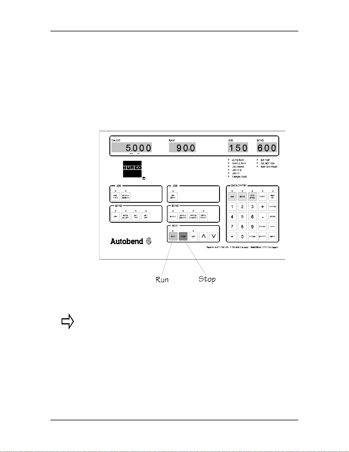
The AB6 control console keypad and display areas are shown below.
Users press the keys on the control console to interact with the system.
Press the Stop key on the control any time a jam occurs between the
gauging surface and the tooling or if an emergency situation arises
involving the AB6 equipment. Refer to the AB6 Programming and
Operations manual for details about the control console.
Here is the AB6 console:
Figure 1-1. AB6 Control Console Keypad
Important
The Stop button does not force the press brake to stop unless an
interlock is wired from the Ram Enable relay (K1) to the press brake
logic.
The press brake’s Stop or E-Stop does not force either control to stop
unless an interlock is wired from the press brake logic to the AB6
relay coil spare relay (K3).
1-4 Revision E Hurco
Page 20
Power Cabinet and Consol e Location
Before operating the gauging system on a press brake, become familiar
with the machine’s components.
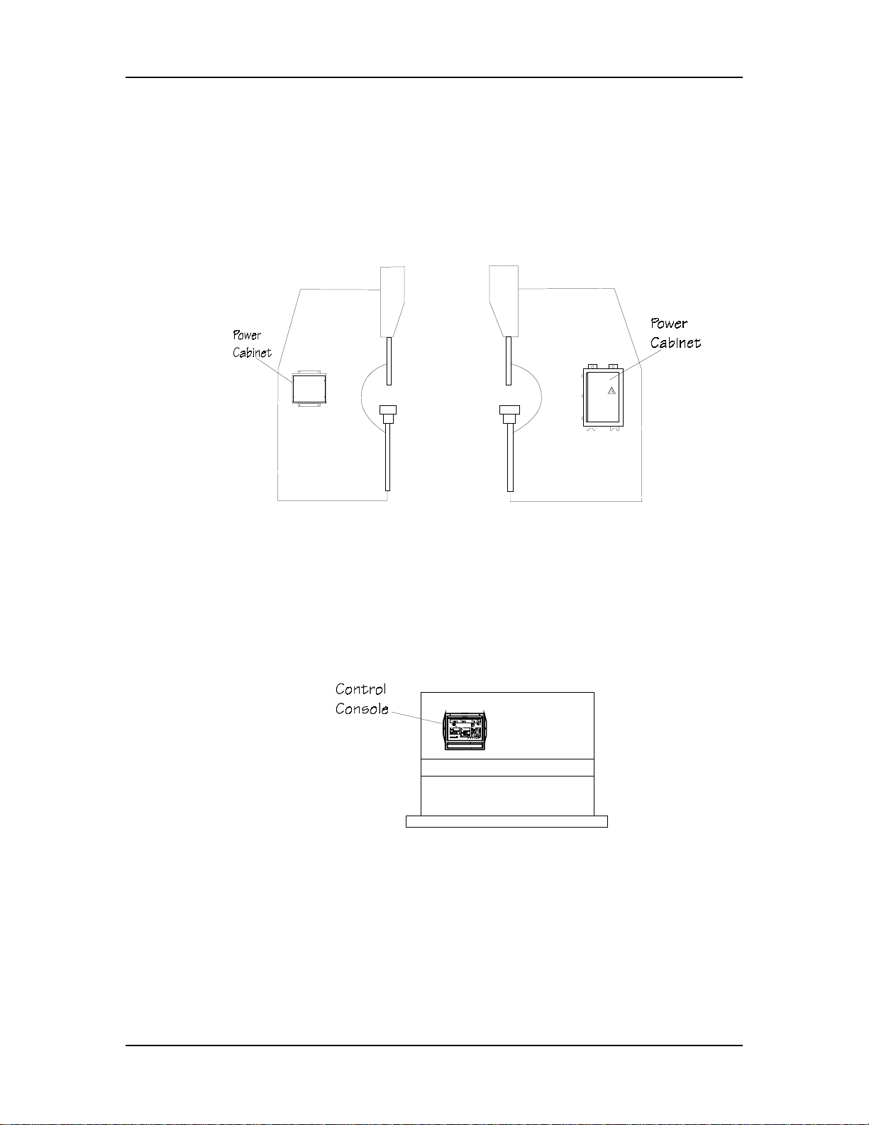
The figures below are examples that show upacting press brakes with the
small and large AB6 power cabinets attached to the side:
Introduction
Figure 1-2. Side Views of Upacting Press Brake with Small and Large Power Cabinets
The figure below shows an upacting press brake with the AB6 control
attached directly to the press brake. An alternative method of attaching the
control console is to attach it with the optional pendant arm. (Refer to the
Installation manual for details.)
Figure 1-3. Front View of Upacting Press Brake with AB6 Control Console Attached
Autobend 6 November, 1999 1-5
Page 21
Installation Manual
Gauges
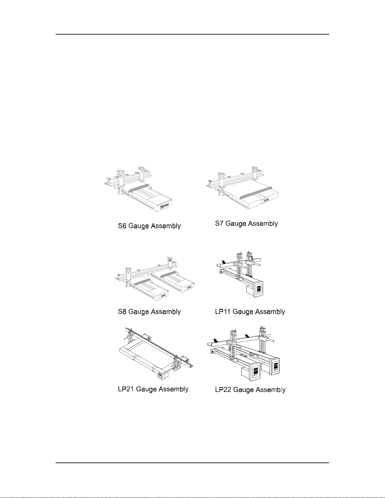
The AB6 operates all S and LP models of Autobend gauges. These gauges
are mounted to the rear of different types of press brakes as discussed in
the “Installation” chapter of this manual.
The figure below illustrates six models: the S6, S7, S8, LP11, LP21, and
LP22. The S6 is narrower than the S7, and the S8 consists of two S6
gauges. The gauge bar length and horizontal adjustment vary among these
gauges. The S8 gauge can be mounted horizontally or vertically, while the
S6 and S7 can only be mounted horizontally. The LP gauges are longer
and narrower than the S gauges.
Figure 1-4. Autobend Gauges
1-6 Revision E Hurco
Page 22
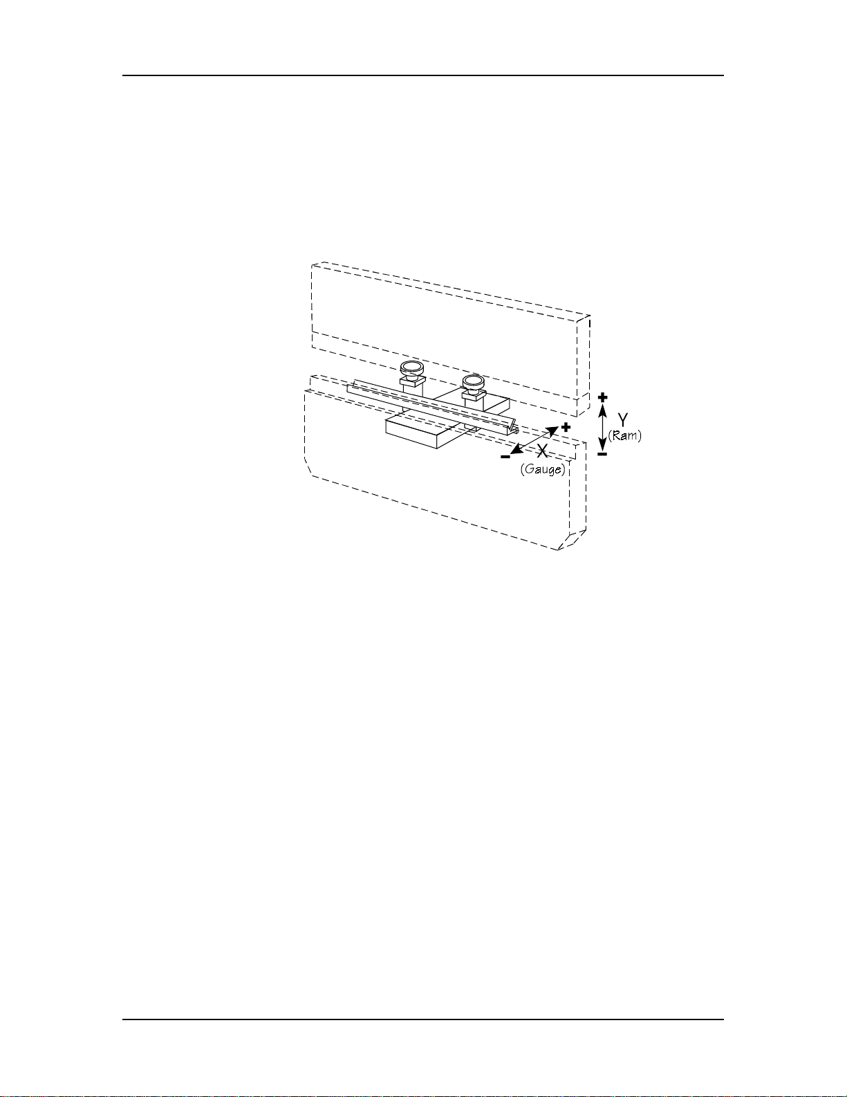
Axes’ Orientation
The axes’ orientation is best observed from the front of the press brake as
shown below. The X-axis positions the gauge bar for the desired flange
lengths. The Y-axis controls the stopping point of the press brake’s ram
for the desired bend to occur. For hydraulic downacting press brakes, the
Y-axis can also control the ram’s opening height and speed change point.
Introduction
Figure 1-5. Typical Axes’ Configuration
Autobend 6 November, 1999 1-7
Page 23

Installation Manual
Owner’s Responsibil i ties
The AB6 owner has several responsibilities regarding safety. First, read
this section of the manual and implement the safety requirements
described. Then be certain that the operators in the shop are properly
trained by Hurco and are using the AB6 as it was intended to be used.
If the Hurco trained operator leaves the shop, the owner is responsible for
providing training for the new operator assigned to run the AB6. Call the
nearest Hurco facility for information about on-site training or other
special training opportunities.
Establish proper procedures to prevent fires and provide approved fire
extinguishers to put out small fires. Of course, large fires must be
extinguished by professional fire fighters. As a safety precaution, many
shops have regular fire drills so that all employees know their
responsibilities during an emergency situation.
Machine Modification
The AB6 was designed to meet a wide range of customer needs. If the
owner feels that the AB6 needs to be modified in any way to meet the
special needs of the shop, Hurco recommends that the owner call Hurco
Technical Support or an authorized Hurco distributor for modification
assistance and a written authorization to proceed. Contact the press brake
manufacturer for information about press brake modification.
If the owner modifies the AB6 in any way without Hurco’s assistance and
a written authorization, the warranty becomes invalid. In addition, such
unauthorized modifications may cause safety hazards that may injure the
operator and damage the AB6. The owner is fully responsible for any
accidents resulting from unauthorized modifications.
1-8 Revision E Hurco
Page 24

Introduction
Hardware and Software
If the owner or an operator modifies the hardware or software by
removing, altering, disabling, or tampering with any safety circuit, safety
switch, or any safety operation and then continues to operate the AB6 with
those modifications, such operation is extremely hazardous, a foreseeable
misuse, and voids the Hurco warranty. If the owner or an operator finds
that such modifications have been made, that person must immediately
switch off the AB6 and prevent its use until it has been repaired. The
owner must then contact a Hurco service representative for assistance in
restoring the AB6 to safe operation.
Important
In many locales, machine hardware or software modification to
override safety protections and continued operation of such a
modified machine is illegal and punishable with a fine and/or
imprisonment.
Installation
The owner is responsible for proper site preparation before the AB6 is
installed as described in this manual. A Hurco Field Service Engineer or
an authorized representative must install the AB6 in the prepared locati on.
This location must not subject the AB6 to uncontrolled cabinet
temperatures or unfavorable work environment conditions that could cause
electronic component failure.
If the owner decides later to move the press brake from its installed
location, and if it is necessary to remove the control console from the press
brake, Hurco recommends that the owner call Hurco for assistance. Hurco
recommends that the owner use a competent rigger with the necessary
equipment to move the press brake to the desired location.
Autobend 6 November, 1999 1-9
Page 25

Installation Manual
Maintenance
The owner must be certain that the shop’s maintenance personnel are
trained.
If at any time the operator or owner determines that the electrical cabinet
must be opened, the power must be shut off to the AB6 and the press brake
before the doors are opened. The only exception to this rule is when the
AB6 or press brake is being serviced for electrical problems. Under those
circumstances, Hurco Field Service should direct the person performing
the work.
Warning
This AB6 must not be serviced, repaired, or maintained
by unqualified or untrained personnel.
Safety Signs
Safety-related signs are affixed to appropriate AB6 system components. A
warning sign appears on the safety decals that must be affixed to specific
areas on the AB6 components. (See the “Installation” chapter for
directions for affixing these decals.) The warning signs alert operators of
the possibility of personal injury and damage to the AB6 and press brake if
they do not follow the described procedure.
Figure 1-6. Warning Decal
The yellow and black caution tape (Hurco Part No. 703-0003-009) is
applied across the top rear of the gauge carriage(s) and the gauge bar(s)
alerting operators to a hazardous area.
Figure 1-7. Caution Tape
1-10 Revision E Hurco
Page 26

Operators’ Responsibilities
To avoid serious personal injury, damage to the AB6, and unproductive
downtime, pay careful attention to safety precautions and proper
maintenance. Press brake operation is often a dangerous task, so operators
must stay alert and be aware of potential hazards. Operators must also
follow the safety regulations of their shops.
Training
All operators must be trained in order to operate an AB6. The operators
who are going to run the press brake must be trained by Hurco or an
authorized representative. Before attempting to run the control, study this
manual and become familiar with the functions and safety features.
While studying the manual, make special note of the caution and warning
messages in the manuals and all warning and instruction plates/decals on
the AB6 and the press brake.
Introduction
Clothing and Other Apparel
Operators should always wear eye protection and safety shoes while in the
work area. Safety glasses with side shields are recommended. Do not wear
items such as loose-fitting clothing, watches, necklaces, rings, and
neckties that could become caught in the moving parts of the AB6 and
press brake.
Personal Care
Operators must follow established working practices and personal hygiene
standards. As part of this effort, they must avoid frequent or prolonged
skin contact with fluids and oils on the sheet metal. Some operators wear
gloves or use a special hand cream to protect their hands from these
chemicals. If operators get chemicals on their hands, they must wash their
hands immediately upon leaving the AB6 and pressbrake and before taking
a break. They must also change clothing that has become contaminated
with fluids and oils.
For complete information about handling industrial chemicals used in
machining, refer to the international Control of Substances Hazardous to
Health (COSHH) materials from the chemical suppliers.
Autobend 6 November, 1999 1-11
Page 27

Installation Manual
System Operation
When operating an AB6, always follow these safety rules:
Warning
• Review all safety information and operating instructions the
press brake manufacturer provides before attempting any
operation.
• Use the press brake’s Emergency Stop circuits to control
emergency situations involving the AB6 and the press brake.
• Use the AB6’s Stop button to control emergency situations
involving the AB6 and the press brake.
• Turn the operator control(s) to Off before attempting to
adjust the system.
• Use proper point of operation safeguarding.
• Adjust the gauging system from the rear of the press brake.
• Keep hands out of the point of operation and clear of the
press brake’s forming tools.
• Never reach across the press brake tooling to make any
adjustment.
• Never attempt to make any adjustment to the system by
reaching through the press brake’s point of operation.
• Check the installation of the carriage arrestor bars before
operating the system.
• Be sure that the gauge bar and flip fingers are correctly
referenced to the press brake’s tooling before attempting
operation.
• When testing the AB6, check the ram adjustment before
stroking the press brake. Set the down limit switch as
required per the press brake’s manufacturer. Tooling must
not bottom out before the ram reaches the low end of its
stroke.
1-12 Revision E Hurco
Page 28

System Operation (continued)
• When testing and running the AB6, never attempt to bend
metal that requires tonnage beyond the capacity of the press
brake or the tooling, whichever is less.
• Never operate a disassembled system.
• Disconnect the external power source before attempting to
connect or make adjustments within the power supply box
or the AB6 power supply cabinet. Only qualified personnel
should service this equipment.
• Before operating the system be sure that installers or
operators will not be struck by the rapid movement of the
gauge bar. Also make certain that nothing interferes with the
gauge movement in either direction.
Note
This list does not include all of the possible hazards regarding the
AB6 and the press brake.
Introduction
Part Dimensions and Fixturing
Never bend a part on the gauging system that is larger than the working
surface of the press brake or that juts out on any side beyond the edges of
the press brake. If a part requires a range that is greater than the guarding
allows, the work must be performed on another system having the
necessary work volume capability.
Operators must follow procedures for referencing the bending material
before starting the AB6. Remember that loose objects, such as wrenches
and chuck keys, can become flying projectiles if not removed from the
gauge bar before the AB6 is started. Be aware of protruding machine
members (such as hoses, piping, or ductwork) when working around the
AB6 and the press brake.
Travel Limits
Safety limit switches provided for each system must not be removed or
bypassed in order to obtain more travel or take short cuts. Serious damage
to the AB6 and personal injury to the operator may result from such
actions. It is also dangerous to bend a part that requires operation outside
the limits of the AB6. A larger press brake should be used for such a part.
Autobend 6 November, 1999 1-13
Page 29

Installation Manual
Part Bending
Always know the locations of the Stop key on the press brake and AB6
control. The operator must be very careful when working in the area of
the gauge. To prevent injury, the gauge should be completely stopped
before the operator attempts to make adjustments to a work piece or the
gauging surface.
Warning
When running programs, always follow these rules:
•
Never press the Run key without knowing exactly what the
AB6 and pressbrake will do!
• Never start the AB6 when the back gauge is in contact with
the work piece.
• Never stand in the rear inside area between the back of the
press brake bed and the gauge bar while the gauge is
moving.
• Never leave the AB6 or the press brake unattended.
Always work within reach of the Stop keys and observe the operation of
the gauge. Running a program out of reach of the Stop key and not
observing the gauge is considered unattended operation and is viewed as a
foreseeable misuse of the AB6.
1-14 Revision E Hurco
Page 30

Subsystem Failure
Maintenance personnel and trained operators need to understand the
maintenance requirements and possible problems associated with the press
brake subsystems. They can become familiar with the subsystem
maintenance requirements by studying the press brake’s maintenance
manual.
Electrical Systems
Clean electrical AC power source, as defined in the ANSI/NFPA 79
standard, is essential to the successful operation and continued reliability
of the AB6. Therefore, the gauging system must be properly connected to
its power source as described in detail in this manual. The system must be
attached to a dedicated, fused, and isolated line with incoming power that
matches the specified, factory-wired, power cabinet voltages, and current
requirements of the AB6 system.
Introduction
Warning
If the AB6 is not properly connected to its power
source, there may be electrical noise and fluctuations
with the power source that will affect safety,
performance, and the warranty. In addition, brown-out
conditions and surges may occur in the shop, and the
AB6 electrical components may fail and require
replacement.
Autobend 6 November, 1999 1-15
Page 31

Installation Manual
Electrical Safety Guidelines
Follow these electrical safety guidelines before operating the AB6:
1. Provide a clean source of electrical power with a separate
dedicated incoming power line (hot, neutral, and ground
wire).
2. Ensure that this source of electrical power is of proper
voltage and is free of electrical sags, surges, spikes, and
noise. This source must be free of inductive loads that might
cause high-frequency electrical noise.
3. Prevent an unwanted ground loop. The electrical control
systems are interconnected to terminate at the central point
ground terminal located inside the AB6 power cabinet. This
single point ground must be connected to the ground circuit
of the electrical power source so that it provides only one
conducting path (between the AB6 power cabinet and the
power cord).
4. Route all AB6 cables to prevent close contact (6" - 10", 150
mm. - 250 mm.) with any press brake control, voltage line,
motor, or other noise-generating devices.
5. Attach all system cables properly to the press brake’s frame.
Loop cables with excessive length. Use the extra large tie
wraps and 3/8" self-tapping screws provided to attach the
cables to the frame.
1-16 Revision E Hurco
Page 32

Introduction
Procedures for Handling Printed Circuit Boards
Static charges are present at all times and in all environments. Damage to
sensitive electronics occurs at lower voltage levels than people can sense.
Static damage may cause total failure or degrade the circuits’ performance
and can eventually lead to intermittent or total failure. Prevent component
damage by discharging static electricity to a ground. Follow the procedures
below.
Before touching, adjusting, or removing a printed circuit board (PCB),
wear a wrist strap grounded to the cabinet or enclosure ground point. If a
grounding wrist strap is not available, touch a grounded point within the
enclosure each time before touching a PCB or electronic assembly. An
example of a grounding point is the metal cabinet’s screws.
Caution
Limit the direct handling of the PCB to reduce the chance of damage.
Keep the PCB in a protective bag until it is installed. Use static
handling procedures before opening the bag and removing the circuit
board. Return all replaced PCBs to the static protective bag.
Autobend 6 November, 1999 1-17
Page 33

Installation Manual
Fire Prevention and Fighting
There are some obvious causes of fires that should be avoided in all shops:
• Storing or handling flammable materials near heat sources
• Not keeping the work area clear of debris such as shop
clothes, cartons, and other shop supplies that could catch fire
If a fire does occur, press the Stop key on the control and on the press
brake and activate the factory’s fire alarm system to evacuate personnel
who are not directly involved with extinguishing a small fire. Shop
personnel may be able to put out small fires using extinguishers approved
for the conditions in their shops. However, if it is clear the fire is
uncontrolled or too large for the shop extinguishers, professional fire
fighters must be called and all shop personnel evacuated.
If a fire has occurred and the shop personnel have extinguished it, it may
still be wise to contact the fire department or fire prevention authorities for
advice to be certain the fire has been completely extinguished and to help
prevent future fires. Fire extinguishers should be tested for proper
operation at least three times a year by a trained and certified inspector.
Additional Safety Information
For additional safety information Hurco recommends the following
sources:
1. National Safety Council
444 N. Michigan Avenue
Chicago, Illinois 60611
2. State, provincial, and local safety codes
3. Worker’s compensation carrier’s loss prevention department
4. Press brake manufacturer
1-18 Revision E Hurco
Page 34

Service Department
The goal of Hurco’s Autobend Service Department is to provide customers
with services necessary to help ensure success in their investment. If
customers experience problems with the AB6 components such as screen
errors, lack of power to the components, or gauge performance that are not
solved by suggestions in the “Error Codes” section of the Programming
and Operations manual, they should contact Hurco’s Service Department
by calling the appropriate phone number listed in the first section of this
manual. The Service Department personnel will attempt to correct
problems in an efficient and timely manner, saving the company
downtime.
The AB6 serial number is located on the door of the AB6 power cabinet’s
data plate. Record the serial number here and on the cover page for
reference:
Introduction
Please provide the following information when calling Hurco’s Service
Department:
1. company name and telephone number
2. name and extension
3. serial number
4. a brief, accurate description of the problem and its specific
symptom(s)
The Hurco Autobend Service Department is committed to helping
customers obtain the maximum benefits from investing in its products.
Call (317) 298-2639 for Hurco’s Autobend Service Department in
Indianapolis.
Autobend 6 November, 1999 1-19
Page 35
Installation Manual
Console Keypad Functions
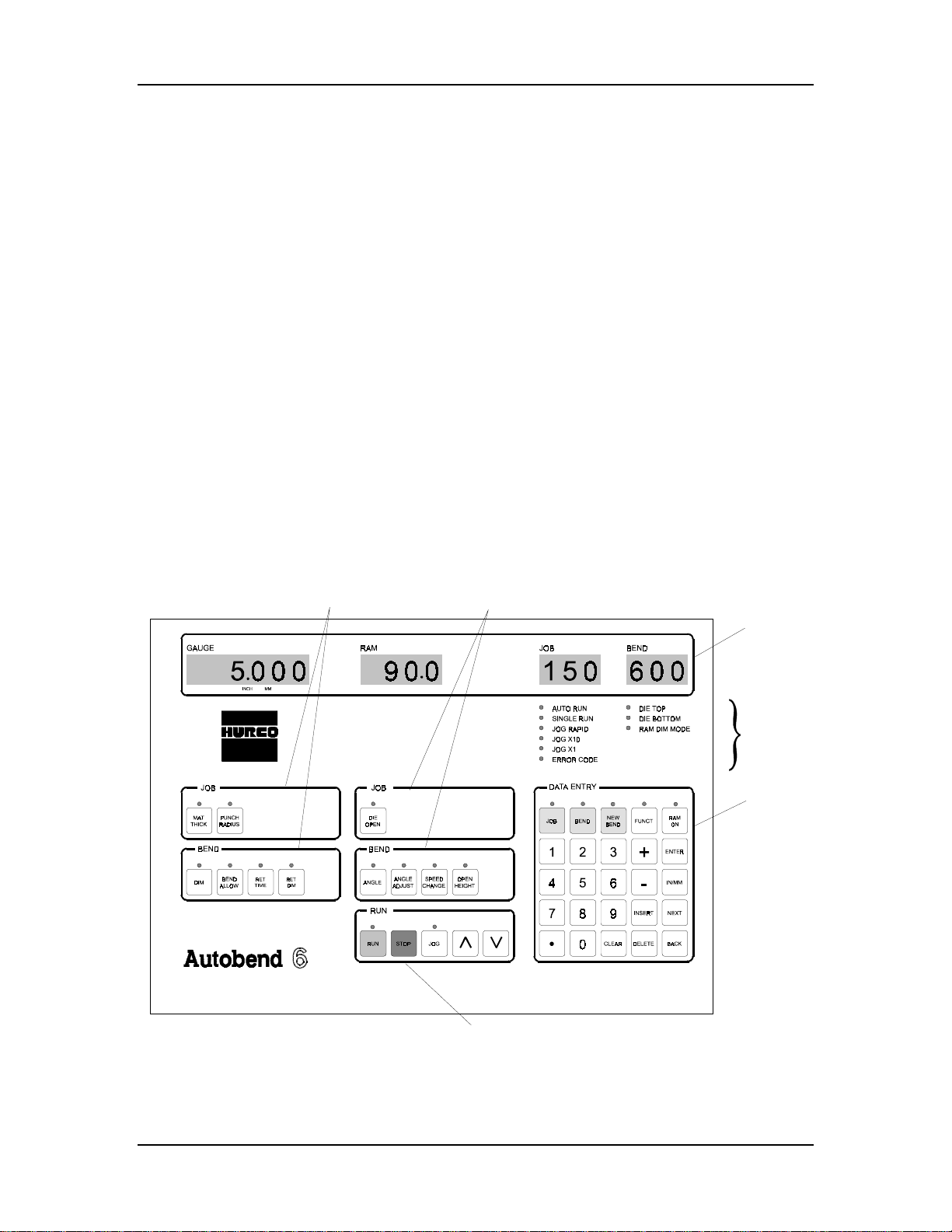
Below are descriptions of the AB6 console keypad functions. Be familiar
with these functions before testing the system.
The AB6 control contains a display group at the top of the control where
programming entries or default values appear. There are also programming
keys with dedicated LEDs (light emitting diodes).
Values for Gauge, Ram, Job and Bend appear in the displays. Single axis
Job and Bend programming keys are below the Gauge display, and dual
axis Job and Bend programming keys are below the Ram display.
The Data Entry keys are grouped together. Use them to select tasks, scan
job and bend lists, perform calculations, select special functions, and input
numbers. Within this group of keys are the yellow Job, Bend, and New
Bend programming keys.
The keys in the Run group are the operation keys. Use them to select Auto
or Single Run mode and to jog the selected axis.
Here is the AB6 control layout:
X-Axis
Programming Keys
®
Optional Y-Axis
Programming Keys
Displays
Operation
LED s
Data
Entry
Keys
Patents: 4,477,754 (US) 1,102,434 (Canada) 1,649,606 & 1,375,124 (Japan)
Operation
Keys
Figure 1-8. AB6 Control Layout
1-20 Revision E Hurco
Page 36

The Programming keys are grouped with the Data Entry keys.
Programming, Job, Bend, and Run keys have dedicated LEDs to show
whether their state is Active (On) or Stand-by (Off). Use the Programming
and Data Entry keys to perform these functions:
Programming Key Function
Job Activate the Job display and input new jobs.
Bend Activate the Bend display and input bend number.
Introduction
New
Bend
Funct Used in conjunction with other programming and data entry keys to enable
Ram
On
Data Entry Key Function
Enter Enter selected data, move cursor the next prompt, transfer Die Top and Die
IN/MM Select measurement unit (inch or metric). This key is used with the Funct
Next Select the next job parameter or bend parameter, depending on mode.
Back Select the previous job parameter or bend parameter, depending on mode.
Insert Insert a new bend.
Delete Delete the displayed job or bend.
+
Activate the Bend display and input a new bend number.
special functions.
Select ram control status (On/Off).
Bottom positions, and transfer the Teach position.
key.
Input positive data entries or perform Calculator functions.
-
Clear Clear displayed data.
0-9 Use the number keys to input numerical values, or to perform special
Input negative data entries or perform Calculator functions.
functions when used in conjunction with the Funct key.
Important
Refer to the Programming and Operations manual for more
information about calibration and job programming.
Autobend 6 November, 1999 1-21
Page 37

Installation Manual
Calibration
The axes automatically calibrate and position to the first bend (i.e., station)
during start-up when a job is programmed and the Run button is pressed.
There are additional calibration procedures to follow for the AB6 control.
Refer to the Programming and Operations manual for details.
Start-up Procedure
The following sections contain procedures for powering up the AB6
control.
Follow these instructions to power up the AB6 system:
1. Turn on the power to the AB6 using the switch on the side of
the AB6 power cabinet. The AB6 control performs this
power-up sequence:
a. All segments of the LEDs light up for
approximately 3 seconds.
b. The software version number appears in the Gauge
display.
c. The date appears in the Ram display.
d. The number of available Jobs and Bends appears in
their displays.
2. Turn on the power to the press brake and start the pump
motor by following the manufacturer’s instructions.
3. Following the power-up sequence, data for the most recently
operated job appears in the Job and Bend displays. Program
the job if it is not already programmed. (Refer to the
“Programming and Operations” chapter of the AB6
Programming and Operations manual for more information.)
4. Press the Job key.
5. Select a job from memory by inputting a Job number, or
program a new job.
6. The axes calibrate and then position to the first bend.
7. The bending operation may begin.
1-22 Revision E Hurco
Page 38

Shut-down Procedure
This section describes procedures for shutting down the AB6 control:
To shut-down the AB6, follow these steps:
1. Press Stop. This disables the servos and turns off the Run
key’s LED.
2. Block the press brake’s ram and turn off the power to the
press brake by following the manufacturer’s instructions.
Introduction
Autobend 6 November, 1999 1-23
Page 39

Installation Manual
1-24 Revision E Hurco
Page 40

Chapter 2
Installation
This chapter contains directions for installing the Autobend 6 (AB6)
control system. Familiarity with this information before beginning the
process provides better results.
Warning
Do not connect electrical cables until completing the
procedures in the “Electrical Connections” section.
Preparation for Installation
Prepare for the installation by following these steps and gathering the
proper tools:
1. Read the “Introduction” chapter of this manual before
attempting to install the system onto the press brake.
2. Lay out the gauging system parts on a clean work area near
the press brake.
3. These tools are required for installing this gauging system:
• Ohmmeter
• Assorted screwdrivers and wrenches
• Allen head wrench set (Metric and U.S. Standard)
• Electric drill (magnetic base drill recommended)
• Assorted drill bits
• Plumb and level
• Center punch and scribe
• Tap handle, assorted taps, and tapping fluid
Autobend 6 November, 1999 2-1
Page 41

Installation Manual
Parts List
The AB6 is foam packaged for protection during shipment. Remove the
parts from the foam packing and inventory them by using the Parts Lists
included with the system.
Recommendations
These instructions represent typical installations and may not have the
same physical appearance as a particular press brake. However, the
instructions apply unless otherwise stated.
Important
If the press brake or its physical location requires mounting
variations not illustrated, remember the following important
recommendations:
• Make certain that the mounting of a component or assembly
does not interfere with the operation of the press brake.
• Mount the gauge frame to the press brake, and make sure the
gauge bar can reach the forming tools.
• Attach the control console and the AB6 power cabinet on
the same side of the press brake. If this arrangement is not
possible, check the control console cable length to be sure it
will reach the power cabinet.
• If it is not possible to mount the AB6 power cabinet directly
to the press brake, use a bonding conductor between the
press brake and the AB6 power cabinet.
Caution
To avoid personal injury be certain to follow safe shop practices. Be
familiar with technical work and press brake operation.
2-2 Revision E Hurco
Page 42
Drill Bits and Tap Sizes
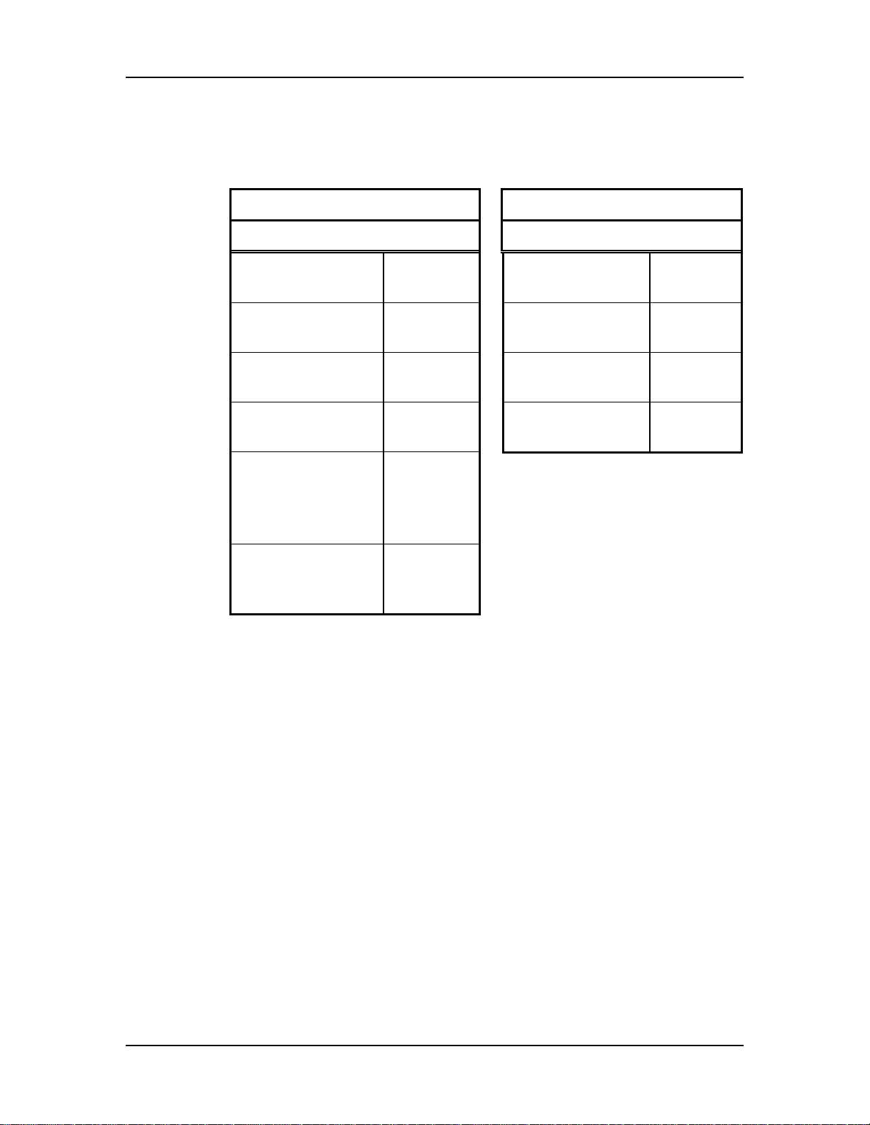
Use these drill bits and tap sizes for installing this gauging system:
U.S. Standard Hardware Metric Hardware
Inches Millimeters
Installation
3/4 - 10 tap
(S7 Gauge)
5/8 - 11 tap
(S6 Gauge)
1/4 - 20 tap 13/64 bit
10-24 tap #24 bit
1/4 - 20 × ½
self-tapping screw
(AB6 small Power
Cabinet)
5/16-18 tap
(AB6 large Power
Cabinet)
21/32 bit
17/32 bit
7/32 bit
Size F bit
M20 × 2.5 P tap
M16 × 2.0 P tap
M8 × 1.25 P tap
M6 × 1.0 P tap
17.50 bit
14.0 bit
6.80 bit
5.0 bit
Autobend 6 November, 1999 2-3
Page 43
Installation Manual
Affixing Safety Decals
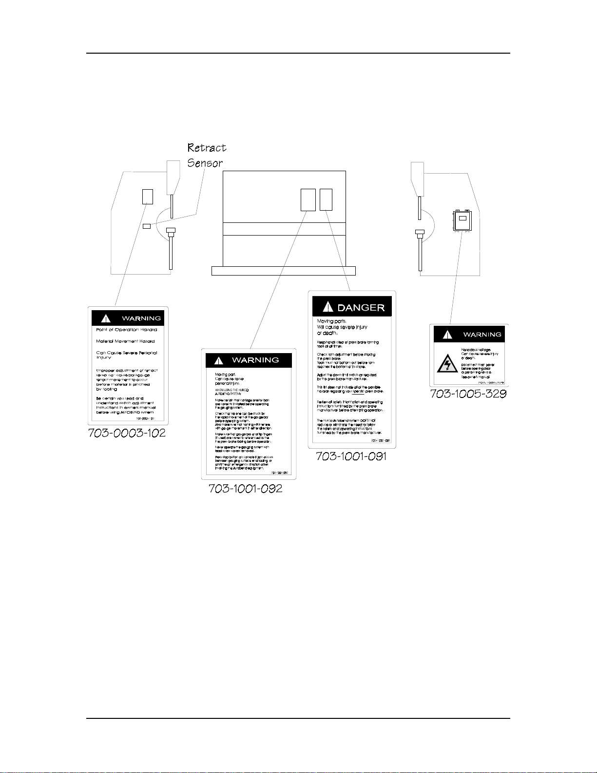
At the beginning of the installation process it is important to affix Hurco’s
safety-related decals to the press brake in the locations shown below.
Figure 2-1. Warning and Danger Decals on Press Brake and Power Cabinet
Note
Customers may order replacement decals at no charge by contacting
Hurco. Please have the AB6 serial number available when placing an
order.
2-4 Revision E Hurco
Page 44

Power Cabinet
The AB6 power cabinet houses the electrical circuits that transfer energy
from the outside power source to the control console. Attach the AB6
power cabinet on the same side that the press brake’s control box is
attached if possible.
There is a warning decal on the AB6 power cabinet’s door that cautions
the operator to disconnect main power before opening it. The decal also
warns about the possibility of personal injury. When it is necessary to
access the electrical circuits inside the AB6 power cabinet, remove the
cabinet’s door.
Caution
Consider cable runs when selecting the area to mount the AB6
power cabinet. Never install cables so they interfere with the press
brake’s throat. It is important to allow clearance for incoming power
and second axis components (for example, linear scale assemblies
and Y-axis motor drive units).
Installation
Follow these instructions to mount the AB6 power cabinet onto the press
brake:
1. If possible, position the power cabinet on the same side as
the press brake’s control box.
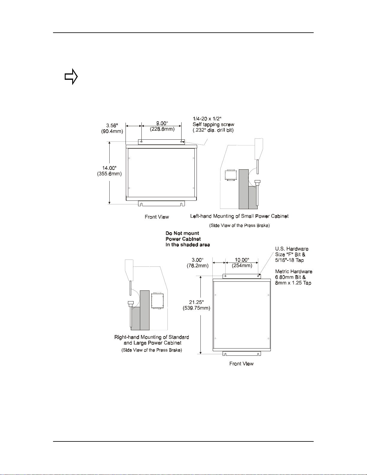
2. Mount the power cabinet in a clear area on the press brake.
Do not mount it in the shaded areas as shown in the figures
on the following pages.
3. Use the power cabinet as a templat e to locate and mark the
centerline of its four (4) mounting holes. Allow at least 6"
(150 mm) of clearance between the bottom of the power
cabinet and the floor for plugging in the cables.
4. Drill the four (4) mounting holes, using the drill bit and tap
sizes indicated in the drawing on the following page.
5. Clean the surface of the press brake and bolt the power
cabinet in position.
Autobend 6 November, 1999 2-5
Page 45
Installation Manual
The figure below illustrates correct AB6 power cabinet mounting to a clear
area on the side of press brakes.
Important
The power cabinet can be mounted to either side of the press brake
provided the cable length requirements are met.
Figure 2-2. AB6 Power Cabinets Mounted to Clear Area on Sides of Press Brakes
2-6 Revision E Hurco
Page 46
Control Console
The front of the AB6 LED control console contains displays, data entry
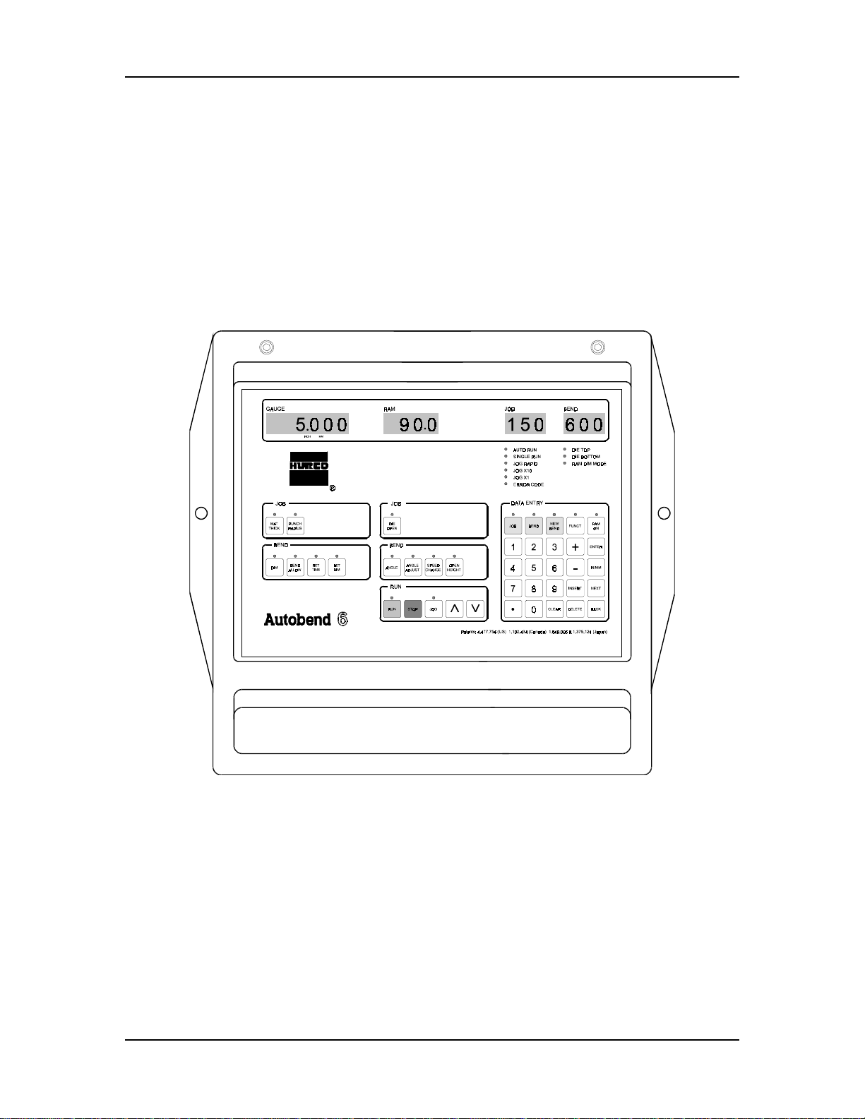
keys, and operation keys. Use the Stop key during an emergency situation
involving the AB6 equipment. For information about the key functions
and running jobs, see the Programming and Operations manual.
There are two methods of mounting the AB6 control console to a press
brake: directly, or with the optional pendant arm. The sections that follow
describe these methods. This is the AB6 control console:
Installation
Figure 2-3. AB6 Control Console
Autobend 6 November, 1999 2-7
Page 47
Installation Manual
Mounting AB6 Control Console Directly to Press Brake
To install the AB6 control console directly to the press brake, follow these
instructions:
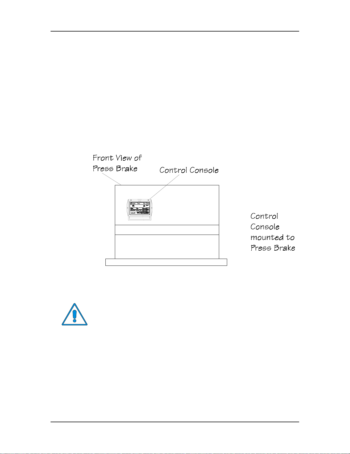
1. Mount the control console in a clear area on the front of the
press brake.
2. Use the control console as a template to locate and mark the
centerline of its two (2) mounting holes.
3. Drill the two (2) mounting holes, using the 5/16" (M8) bolt
drill bit and tap sizes.
4. Clean the surface and bolt the control console in position.
Figure 2-4. AB6 Control Console Mounted Directly to an Upacting Press Brake
Caution
Do not mount the control console on a moving part of the press
brake or where it could cause interference. The placement of the
control console depends on the type of press brake.
2-8 Revision E Hurco
Page 48
Mounting Control Console with Optional Pendant Arm
To install the optional pendant arm to the press brake, follow these
instructions:
Caution
Make sure to position the pendant arm and the control console so
they do not interfere with the press brake’s operation.
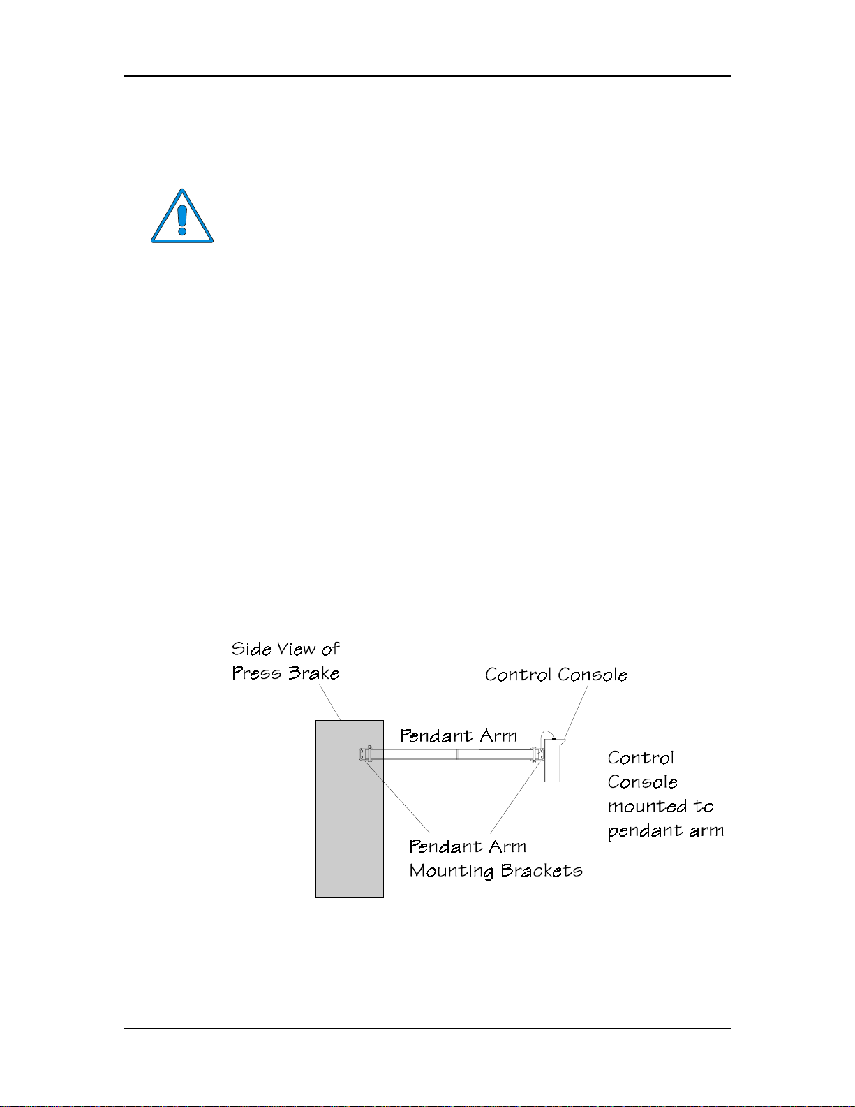
1. Determine the position of the pendant arm so the control
console is at the operator’s eye level. The pendant arm
projects approximately 40" (1016 mm) outward from the
press brake.
2. Determine the correct position of the pendant arm bracket.
Locate and mark the centerline of its four (4) mounting holes
on the press brake’s surface. Be sure that the top of the
bracket is level and square against this surface.
Installation
3. Drill and tap the holes for the bracket in the press brake.
4. Use the four (4) 5/16-18 x 3/4 LG (M8 x 20 LG) SHCS to
attach the pendant arm bracket to the press brake.
5. Attach the control console’s pendant arm bracket with the
four (4) M8 x 1.25 P x 16 LG SHCS to rear of the control
console.
Figure 2-5. AB6 Control Console Mounted to Press Brake with Pendant Arm
Autobend 6 November, 1999 2-9
Page 49
Installation Manual
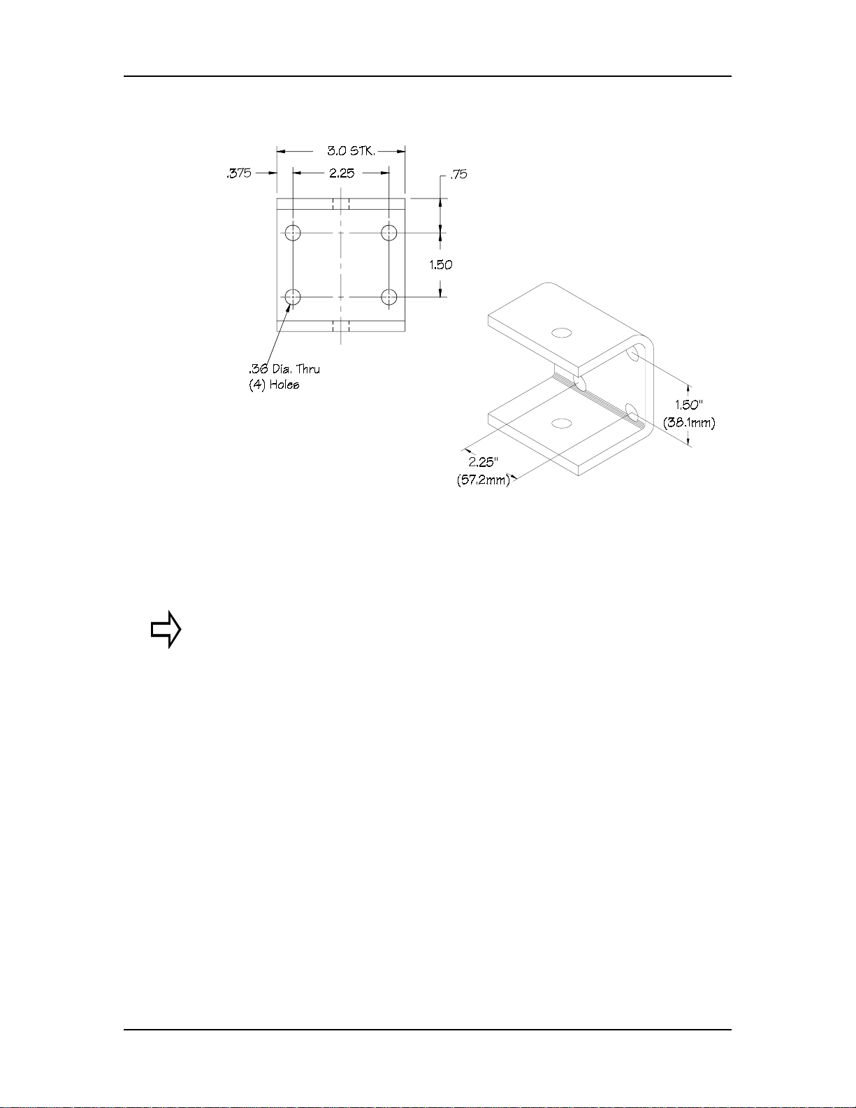
The figure below shows the pendant arm’s mounting plate dimensions:
Figure 2-6. Optional AB6 Pendant Arm Bracket and Dimensions
Important
If using the optional pendant arm, install it onto the press brake then
mount the console to the arm.
2-10 Revision E Hurco
Page 50
Gauge Installation
Because of the different types of Autobend gauges and types of press
brakes, this section is organized according to the installation steps.
Detailed instructions for mounting single and dual gauge systems follow.
Be sure to pay close attention to the subheadings that identify choices for
the process. The “Where can we go from here?” messages identify the
ending of a particular section and lead to the appropriate section.
Types of Gauges
The AB6 control console operates all models of Autobend gauges. These
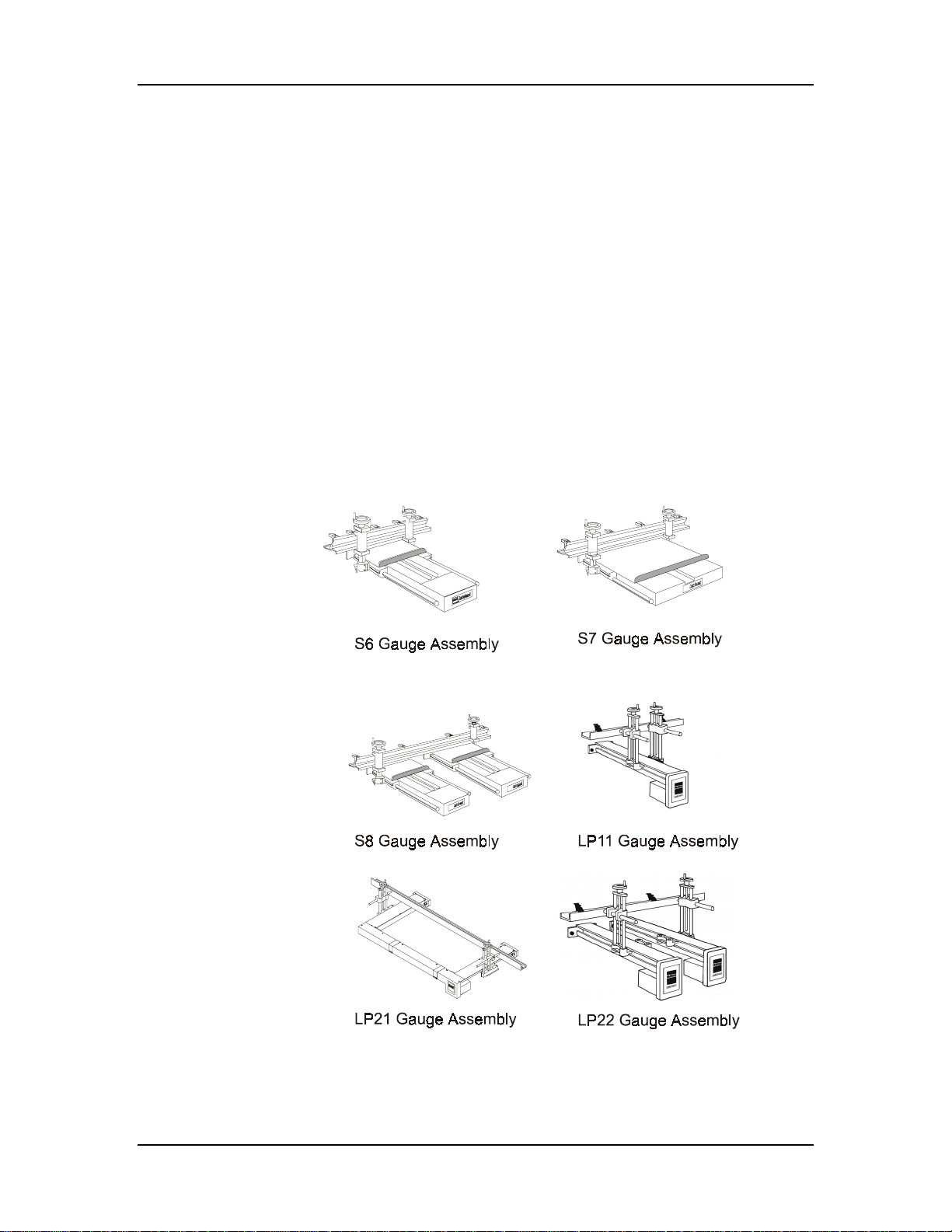
gauges are mounted to the rear of different types of press brakes. The
figure below illustrates the S6, S7, S8, LP11, LP21, and LP22 gauges.
This section also contains installation procedures for the LP22-54 and
vertical S8 gauges.
Installation
Figure 2-7. Types of Autobend Gauges
Autobend 6 November, 1999 2-11
Page 51

Installation Manual
Gauge Installation Overview
Here are the basic steps to the gauge installation process:
1. Locate and mark the rear centerline of the press brake.
2. Determine the gauge height.
3. If drilling and tapping are necessary to mount the gauge(s),
determine the bolt hole locations and mark their centerlines.
a. Use a plumb and level to ensure the holes are
b. Drill and tap the holes.
c. If the mounting surface is irregular or not
d. Thoroughly clean the mounting surface before
parallel to the top of the press brake.
machined, use shims between the press and the
gauge(s).
attaching the gauge.
4. Attach the gauge to the press brake and install the mounting
bolts and washers. Make sure the gauge is level front to back.
Tighten the bolts securely against the washers.
5. Wipe down the lead screw and carriage ways with a soft, lint-
free cloth. Apply a light film of S.A.E. #10 machine oil to the
lead screw and both rod ways.
6. Mount the gauge bar as described in the “Gauge Bar and
Mounting Devices” section of this manual.
7. Consult the “Maintenance” chapter for maintenance
procedures.
Where can we go from here?
Begin with the “Centerline of Press Brake” section of this chapter.
2-12 Revision E Hurco
Page 52
Centerline of Press Brake
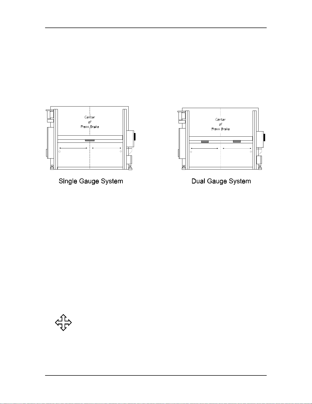
Locate and mark the rear centerline of the press brake between the inside
of the housings at the rear of the press.
• The gauge attaches to the bed on a downacting press brake.
• The gauge attaches to the ram on an upacting press brake.
Installation
Figure 2-8. Centerline of Press Brakes with Single and Dual Gauge Systems
Where can we go from here?
Depending on the press brake’s configuration, refer to either the
“Dovetail Slots,” “Die Retainer Plates,” or “Gauge Mounting”
section in this chapter before mounting the gauge to the press brake.
Autobend 6 November, 1999 2-13
Page 53
Installation Manual
Dovetail Slots
For press brakes with dovetail slots in the rear of the bed, mounting can be
accomplished easily without drilling. Use the dovetail bolts, flat washers,
and nuts in the installation kit.
Die Retainer Plates
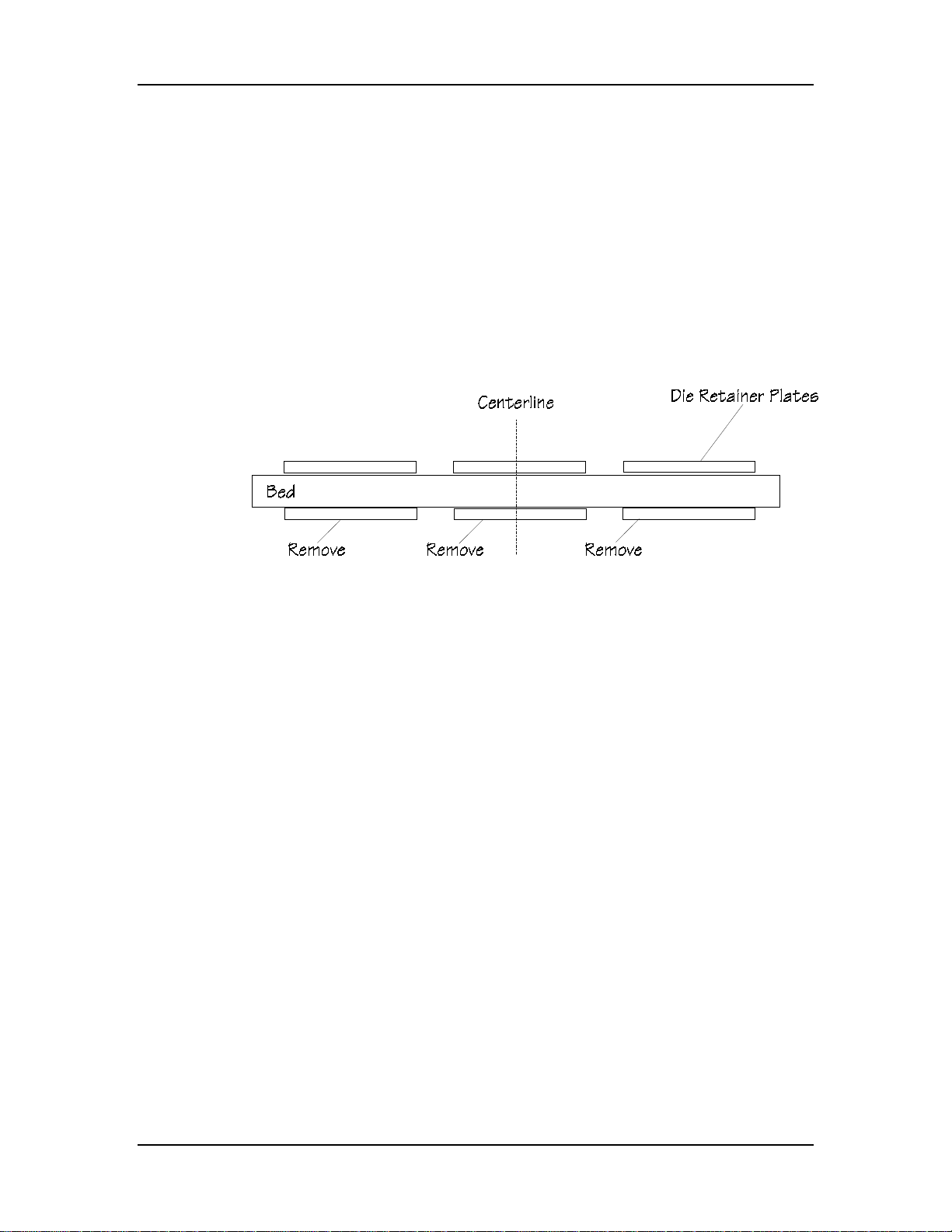
Follow these steps for press brakes that use die retainer plates:
1. Remove the die retainer plates where the gauge will mount.
(See the figure below.)
Figure 2-9. Top View of Bed - Upacting Press Brake
2. Install the support pins into the front surface of the gauge’s
mounting plate as shown in the figures on the following page.
3. If the mounting surface is irregular or not machined, use
shims between the press and the gauge’s mounting plate.
4. Place the die retainer plates over the bolts and support pins.
2-14 Revision E Hurco
Page 54
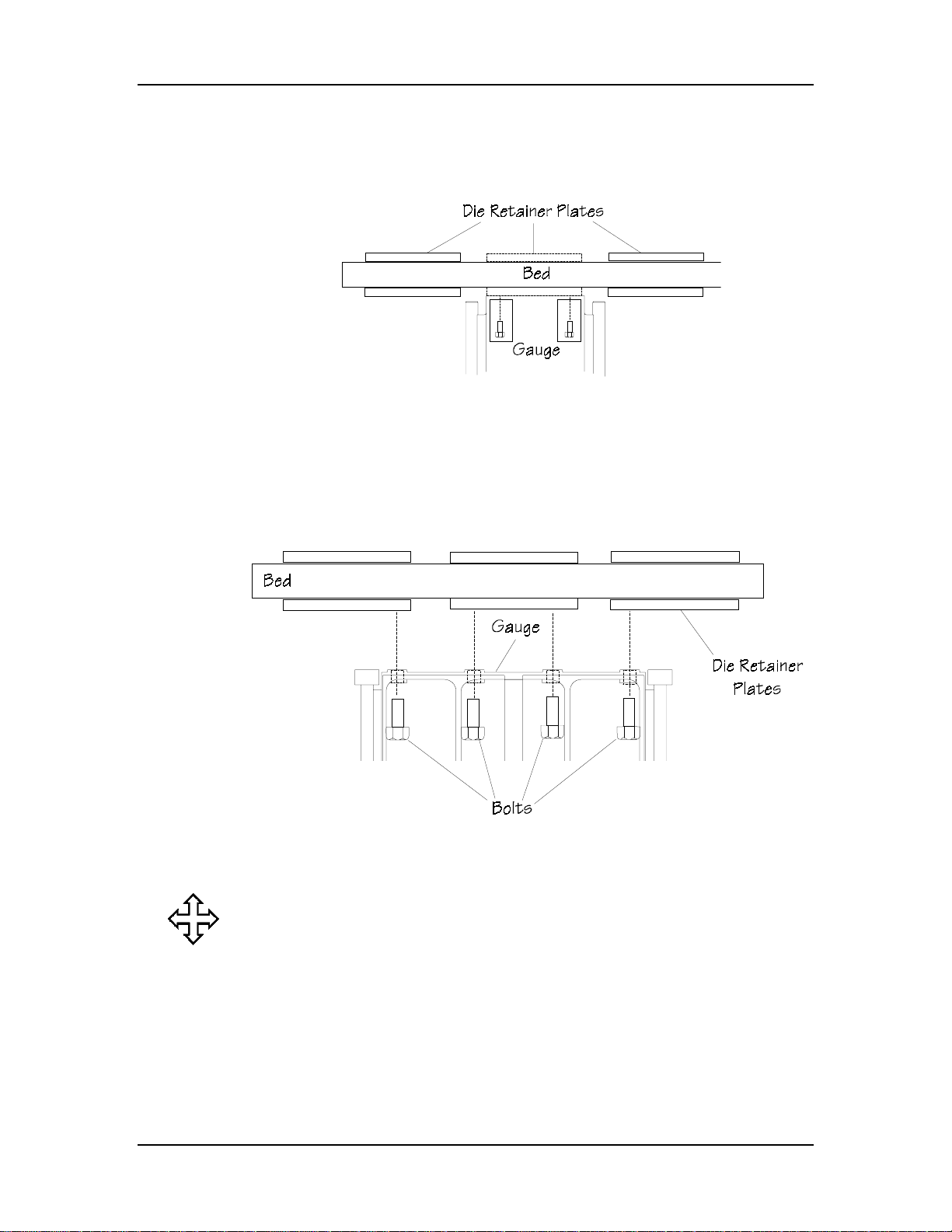
Die Retainer Plates with S6 or S8 Gauges
This figure represents an S6 or one S8 gauge:
Figure 2-10. Top View of S6 or one S8 Mounting on Upacting Press Brake
Die Retainer Plates with S7 Gauges
This figure represents an S7 gauge:
Installation
Figure 2-11. Top View of S7 Mounting on Upacting Press Brake
Where can we go from here?
Proceed to the “Gauge Mounting” section of this chapter.
Autobend 6 November, 1999 2-15
Page 55

Installation Manual
Gauge Mounting
If gauge mounting holes need to be drilled and tapped, it is important to
remember that different types of gauges have different mounting hole
requirements. This section describes procedures for locating, drilling, and
tapping mounting holes for different types of gauges and press brakes.
Number of Gauge Mounting Holes
The number of mounting holes varies among the types of gauges:
Gauge Mounting Holes
S6 2
S7 4
S8 4 (2 for each gauge)
LP11 2
LP21 4 (2 for each gauge)
LP22 4 (2 for each gauge)
LP22/54 4 (2 for each gauge)
2-16 Revision E Hurco
Page 56
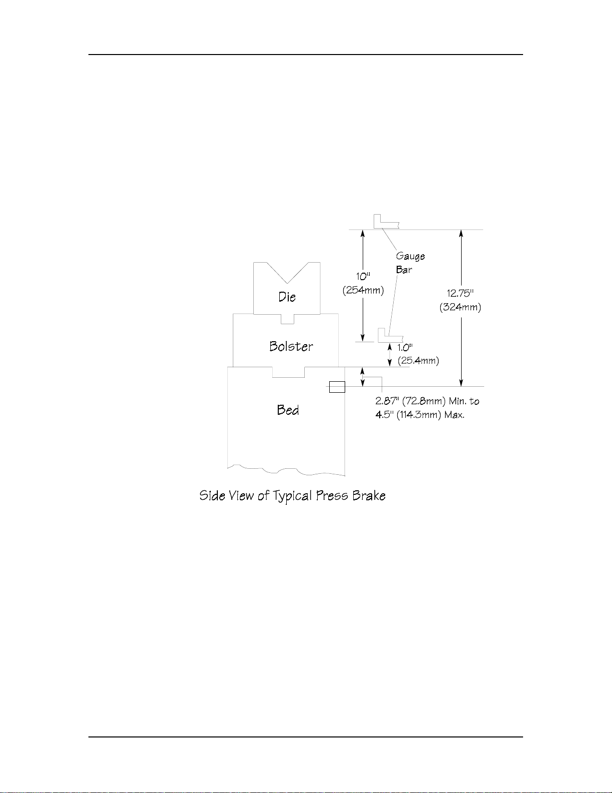
Installation
Gauge Height
Position the gauge so the gauge bar can be vertically adjusted to fit
different die heights.
1. Locate the gauge’s mounting holes approximately 10" below
the top of the lowest die. (See the figure below.)
2. Use a plumb and level to ensure the mounting holes are
parallel to the top of the press brake’s bed.
Figure 2-12. Configuration to Determine Gauge Mounting Height
Autobend 6 November, 1999 2-17
Page 57
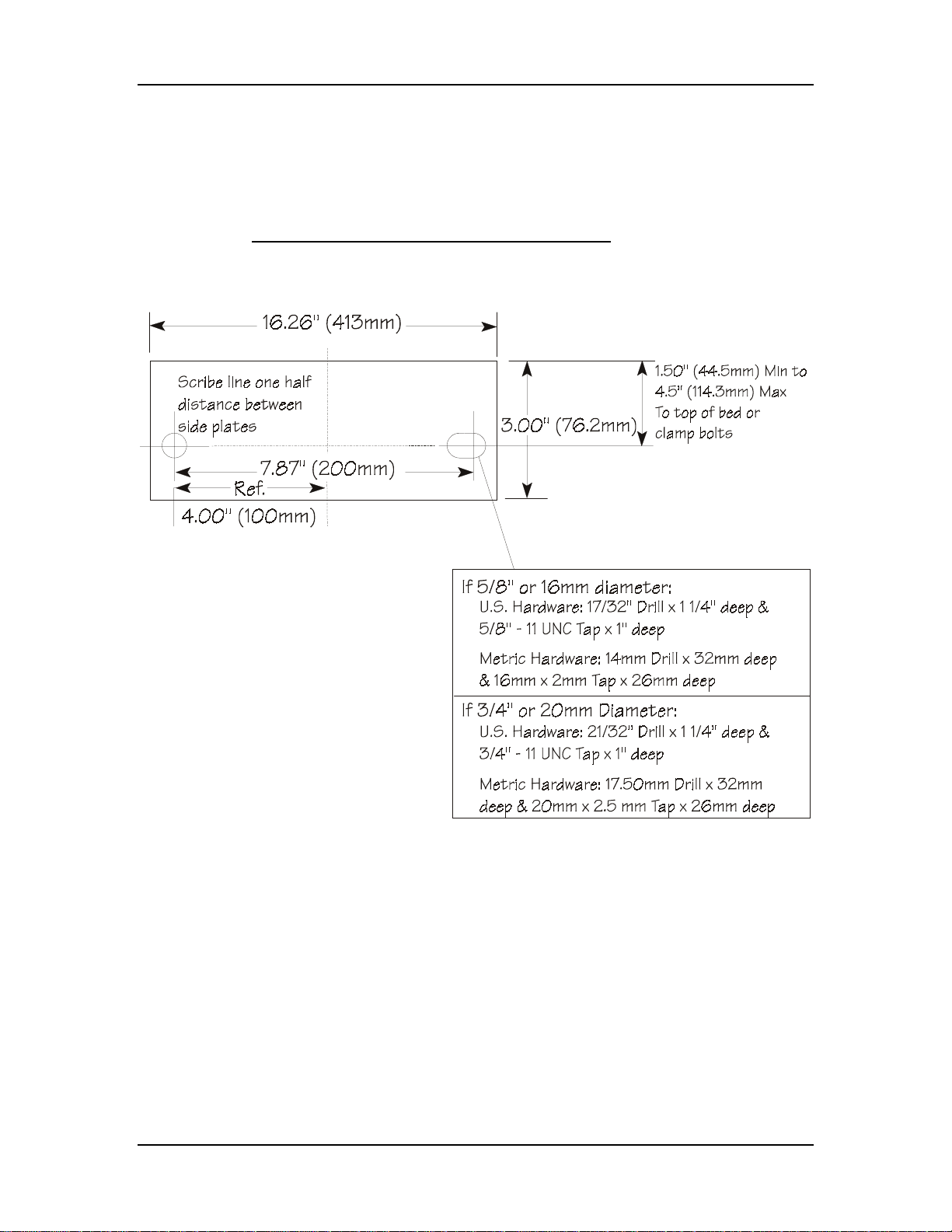
Installation Manual
S6 Gauge Mounting Hole Dimensions
This section contains measurements for correct placement of mounting
holes for the S6 gauge and different types of press brakes.
Hydraulic/Mechanical or Upacting Press Brakes
For hydraulic/mechanical or upacting press brakes, refer to these figures:
Figure 2-13. S6 Gauge Mounting Pattern
2-18 Revision E Hurco
Page 58
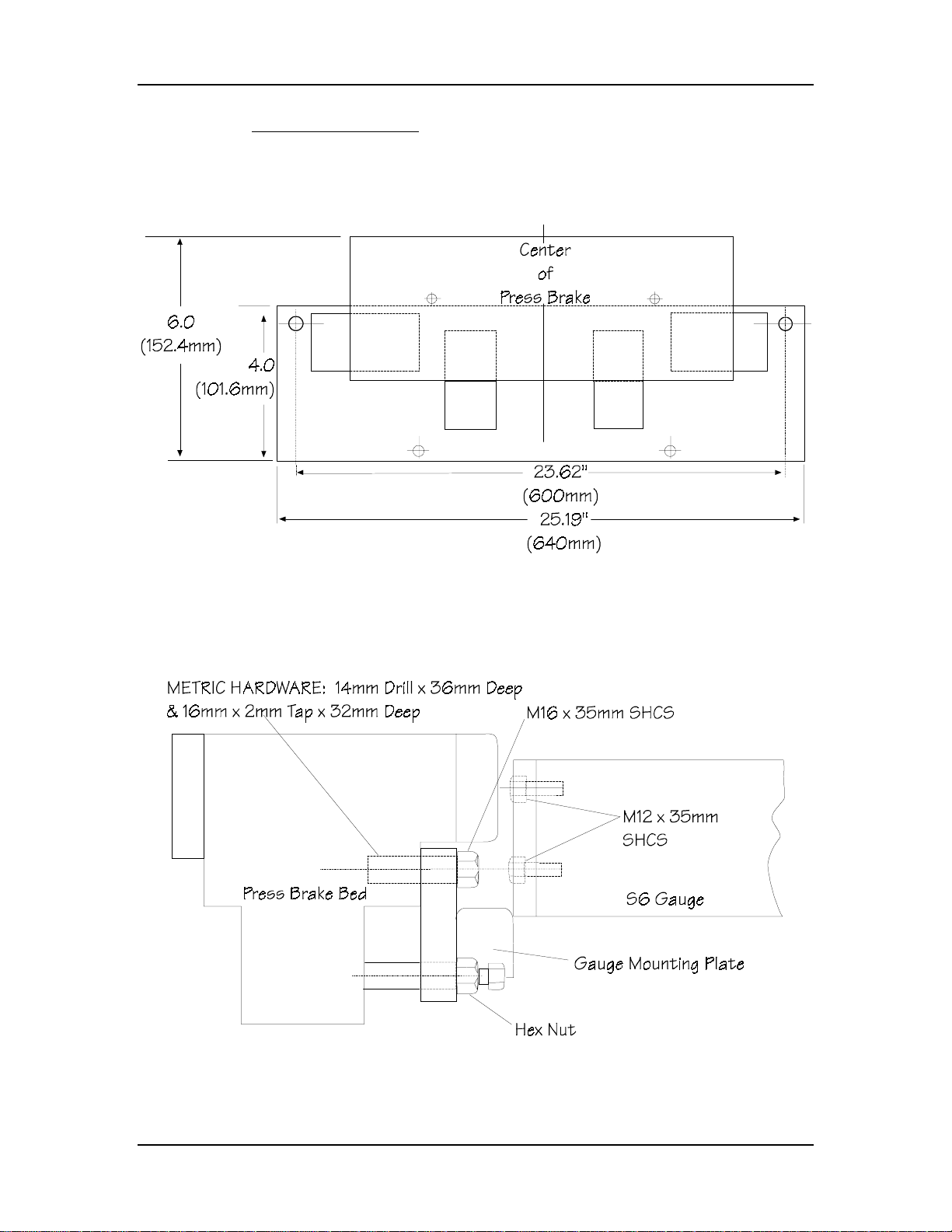
Installation
Komatsu Press Brakes
Autobend gauges are attached to Komatsu press brakes with mounting
plates. For Komatsu press brakes, refer to these figures:
Figure 2-14. Komatsu S6 Mounting Plate
Drill and tap to the size and depth recommended in the figure below.
Figure 2-15. Komatsu S6 Mounting Configuration
Autobend 6 November, 1999 2-19
Page 59

Installation Manual
Attach the mounting plate for the S6 gauge to the Komatsu press brake by
following these instructions:
1. Position the mounting plate to the press brake.
2. Attach with the mounting bolts and washers.
3. Tighten the bolts securely.
Note
Adjust the leveling screws as required to prevent cocking and to
level the gauge assembly.
Where can we go from here?
Proceed to the “Attaching Gauge to Press Brake” section in this
chapter.
2-20 Revision E Hurco
Page 60
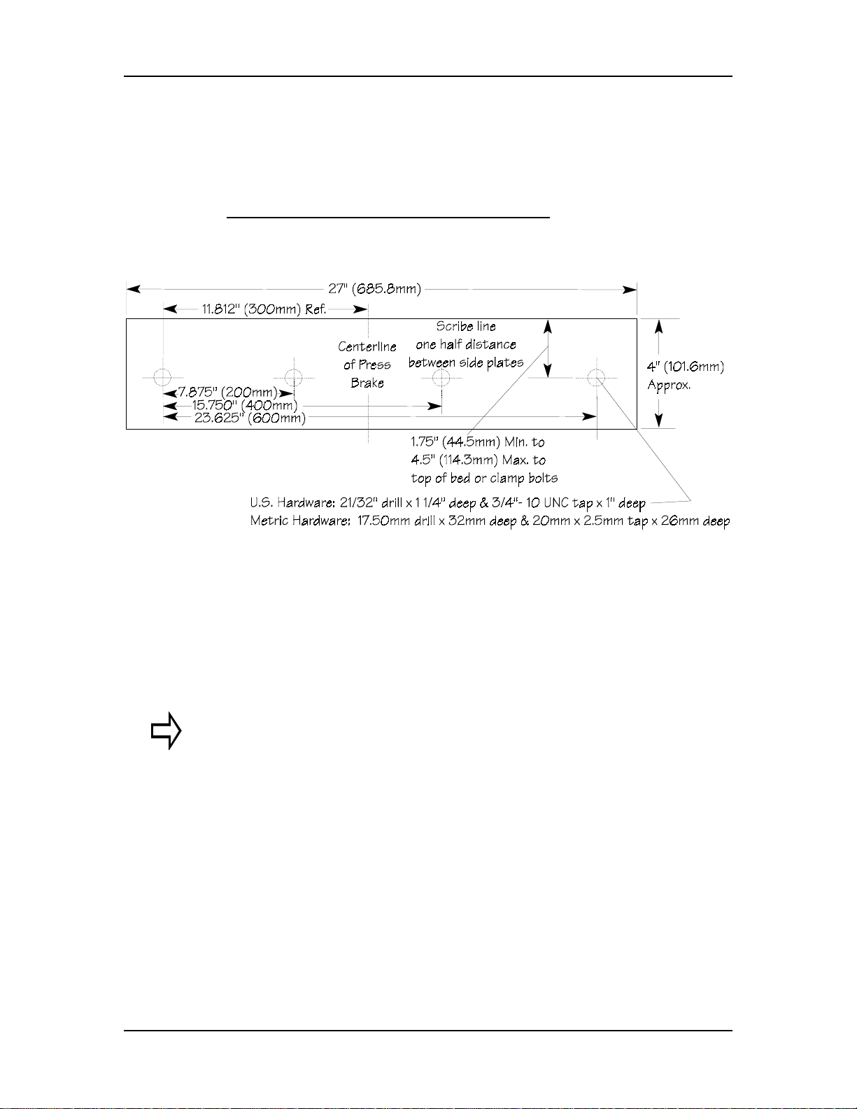
Installation
S7 Gauge Mounting Hole Dimensions
This section contains measurements for correct placement of mounting
holes for the S7 gauge and different types of press brakes.
Hydraulic/Mechanical or Upacting Press Brakes
For hydraulic/mechanical or upacting press brakes, refer to this figure:
Figure 2-16. S7 Mounting Pattern
Important
Remove the left and right covers from the S7 gauge. Do not re-install
the covers until completing the cable connections as outlined in the
“Electrical Connections” section of this chapter.
Autobend 6 November, 1999 2-21
Page 61
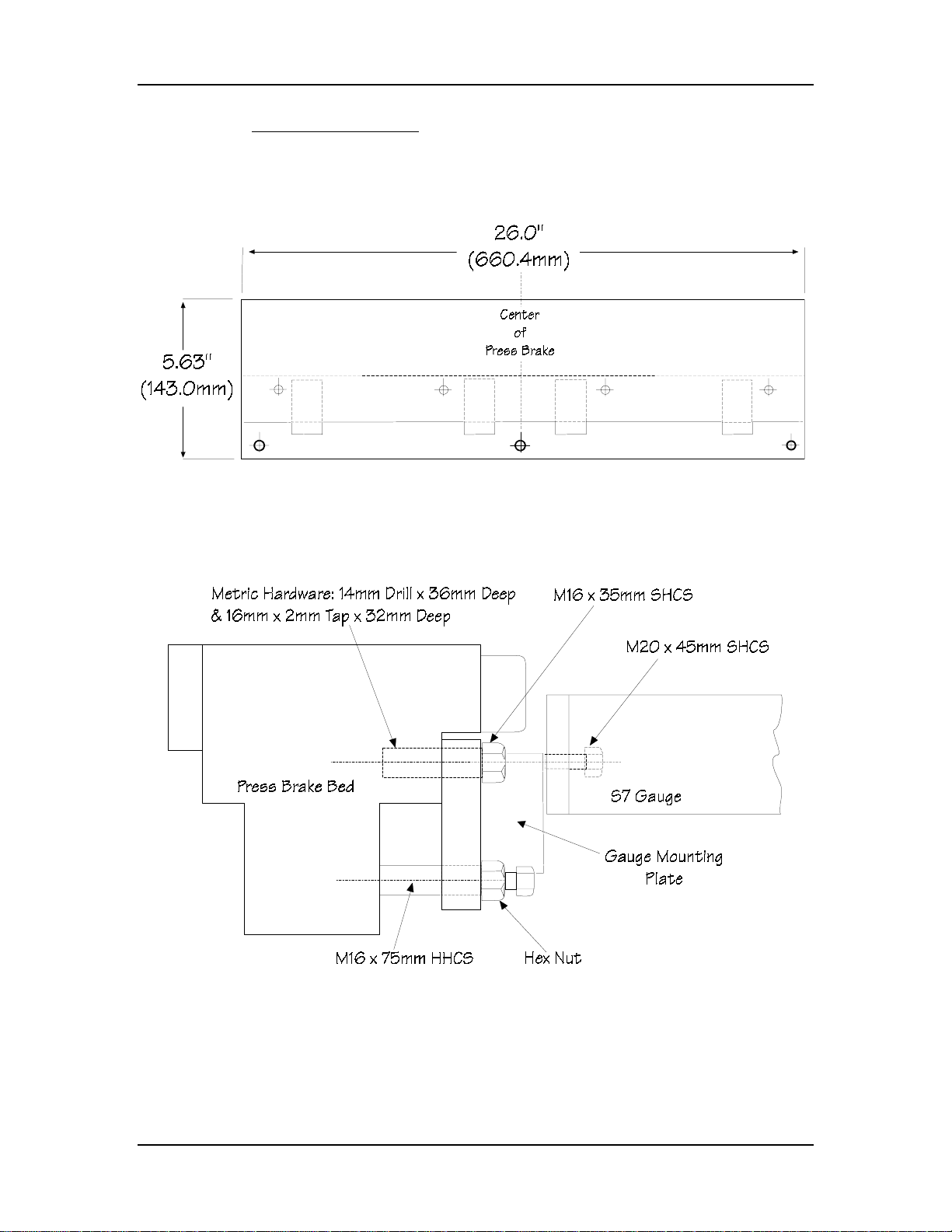
Installation Manual
Komatsu Press Brakes
Autobend gauges are attached to Komatsu press brakes with mounting
plates. For Komatsu press brakes, refer to these figures:
Figure 2-17. Komatsu S7 Gauge Mounting Plate
Drill and tap to the size and depth recommended in the figure below.
Figure 2-18. Komatsu S7 Mounting Configuration
2-22 Revision E Hurco
Page 62

Installation
Attach the mounting plate for the S7 gauge to the Komatsu press brake by
following these instructions:
1. Position the mounting plate to the press brake.
2. Attach with the mounting bolts and washers.
3. Tighten the bolts securely.
Note
Adjust the leveling screws as required to prevent cocking and to
level the gauge assembly.
Where can we go from here?
Proceed to the “Attaching Gauge to Press Brake” section in this
chapter.
Autobend 6 November, 1999 2-23
Page 63
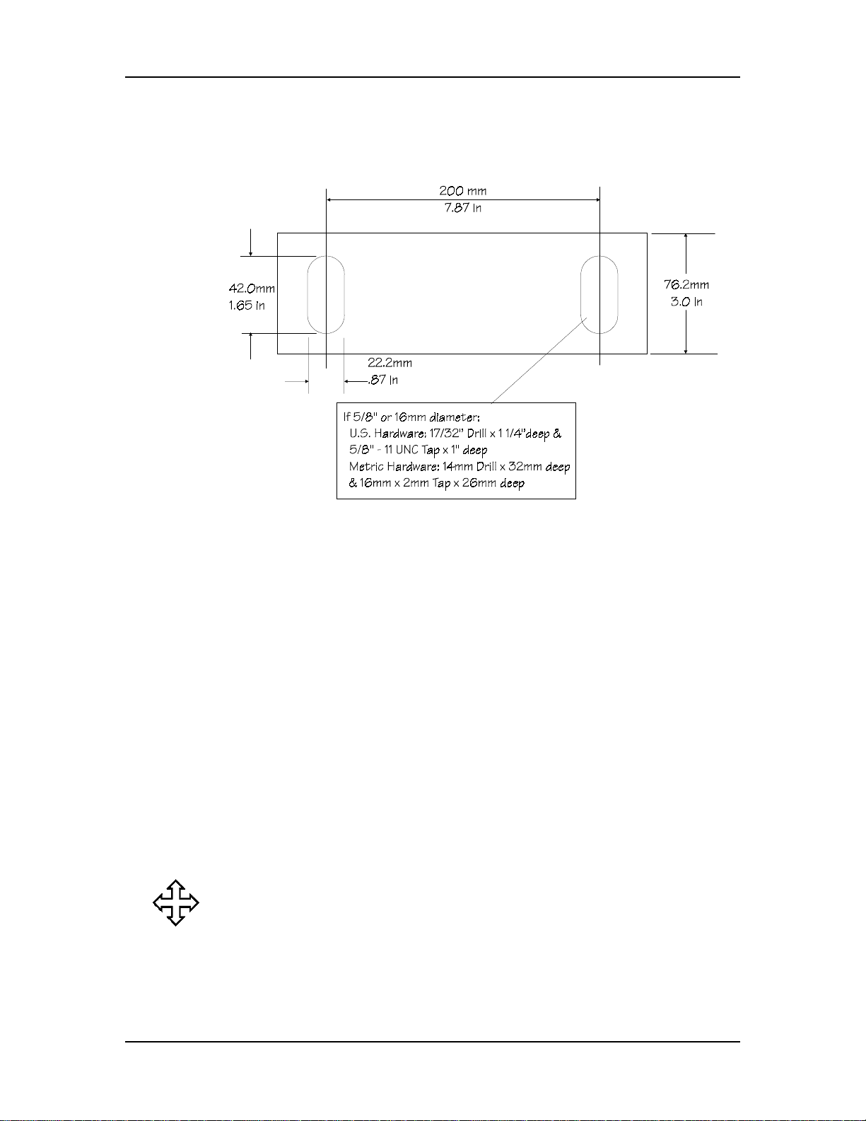
Installation Manual
LP11 Gauge Mounting Hole Dimensions
For hydraulic/mechanical or upacting press brakes, refer to this figure:
Figure 2-19. LP11 Mounting Pattern
Where can we go from here?
Proceed to the “Attaching Gauge to Press Brake” section of this
manual.
2-24 Revision E Hurco
Page 64
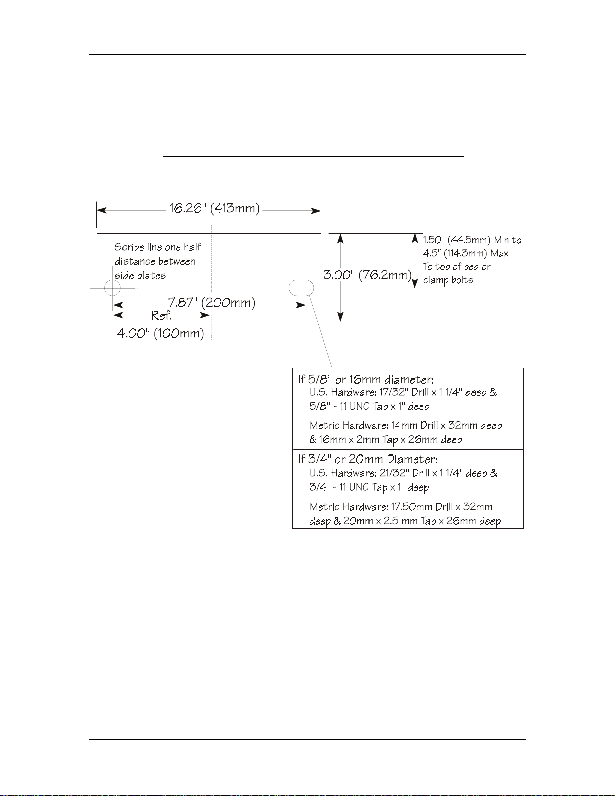
Installation
Dual Gauge Mounting Hole Dimensions
This section contains measurements for correct placement of mounting
holes for dual gauges and different types of press brakes.
S8 Gauges on Hydraulic/Mechanical or Upacting Press Brakes
For hydraulic/mechanical or upacting press brakes, refer to this figure:
Figure 2-20. S8 Mounting Pattern
Autobend 6 November, 1999 2-25
Page 65
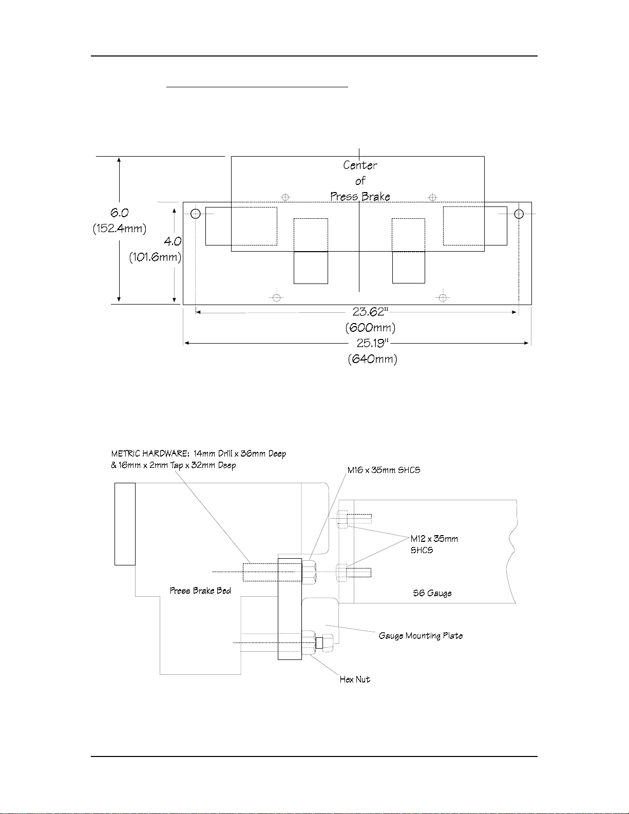
Installation Manual
S8 Gauges on Komatsu Press Brakes
Autobend gauges are attached to Komatsu press brakes with mounting
plates. For Komatsu press brakes, refer to these figures:
Figure 2-21. Komatsu S8 Mounting Plate
Drill and tap to the size and depth recommended in the figure below.
Figure 2-22. Komatsu S8 Mounting Configuration
2-26 Revision E Hurco
Page 66

Installation
Attach the mounting plate for the S8 gauge to the Komatsu press brake by
following these instructions:
1. Position the mounting plate to the press brake.
2. Attach with the mounting bolts and washers.
3. Tighten the bolts securely.
Note
Adjust the leveling screws as required to prevent cocking and to
level the gauge assembly.
Where can we go from here?
Proceed to the “Attaching Gauge to Press Brake” section in this
chapter.
Autobend 6 November, 1999 2-27
Page 67
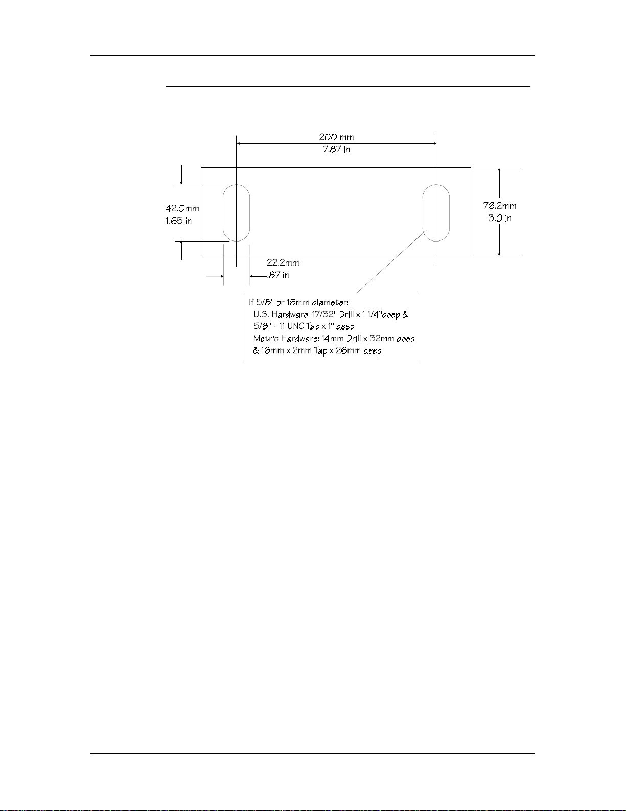
Installation Manual
LP21 and LP22 Gauges—Hydraulic/Mechanical or Upacting Press Brakes
For hydraulic/mechanical or upacting press brakes, refer to this figure:
Figure 2-23. LP21 and LP22 Mounting Pattern
2-28 Revision E Hurco
Page 68

Installation
X Dimension Tables for Dual Gauges
The location of the gauges for a dual gauge system is determined by
measuring the length of the gauge bar and calculating the X Dimension
from the centerline of the press brake. The X Dimension is the distance
from the press brake’s centerline to the inside bolt center for each gauge.
Refer to the appropriate X Dimension Table in this section and the
“Mounting Dimensions for Dual Gauges” section to determine the correct
location to mount the gauges.
S8 Gauges on Hydraulic/Mechanical and Upacting Press Brakes
X Dimension Table
Gauge Bar Length X Dimensions from Centerline
Inches Millimeters Inches Millimeters
90 2286.0 22 560.0
96 2438.4 22 560.0
102 2590.8 27 700.0
108 2743.2 31 785.0
114 2895.6 31 785.0
120 3048.0 36 900.0
126 3200.4 36 900.0
132 3352.8 43 1100.0
138 3505.2 43 1100.0
144 3657.6 43 1100.0
150 3810.0 43 1100.0
156 3962.4 51 1300.0
162 4114.8 51 1300.0
168 4267.2 51 1300.0
Table 1. S8 Gauges on Hydraulic/Mechanical and Upacting Press Brakes
X Dimension
Autobend 6 November, 1999 2-29
Page 69

Installation Manual
S8 Gauges on Komatsu Press Brakes
X Dimension Table
Gauge Bar Length X Dimensions from Centerline
Inches Millimeters Inches Millimeters
90 2286.0 27.56 700.0
96 2438.4 27.56 700.0
102 2590.8 27.56 700.0
108 2743.2 35.43 900.0
114 2895.6 35.43 900.0
120 3048.0 35.43 900.0
126 3200.4 35.43 900.0
132 3352.8 43.31 1100.0
138 3505.2 43.31 1100.0
144 3657.6 43.31 1100.0
150 3810.0 43.31 1100.0
156 3962.4 51.18 1300.0
162 4114.8 51.18 1300.0
168 4267.2 51.18 1300.0
Table 2. S8 Gauges on Komatsu Press BrakesX Dimension
2-30 Revision E Hurco
Page 70
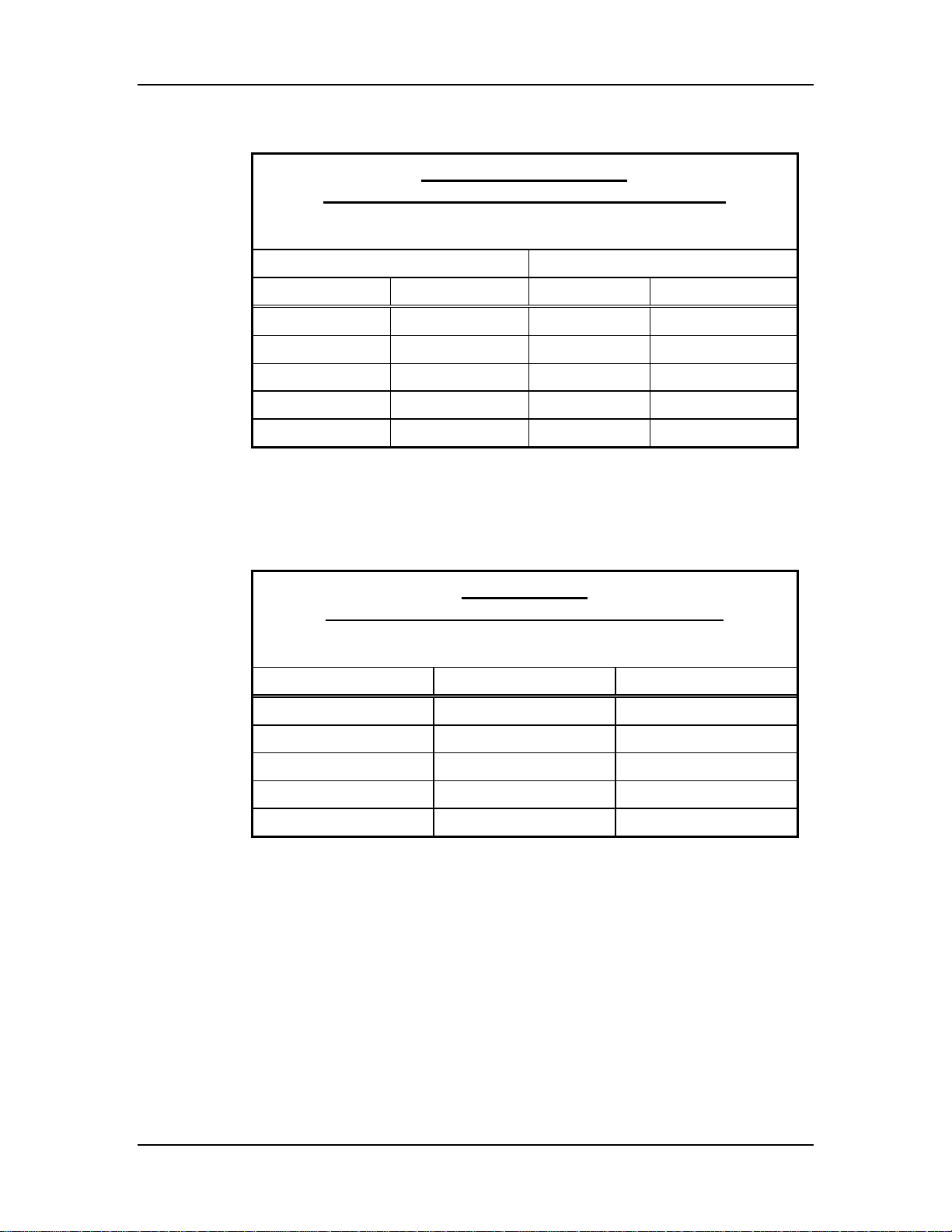
Installation
LP22, LP22/54 Gauges on
Hydraulic/Mechanical and Upacting Press Brakes
X Dimension Table
Gauge Bar Length X Dimensions from Centerline
Inches Millimeters Inches Millimeters
72 1828.8 16.94 430.0
90 2286.0 25.94 659.0
114 2895.6 34.94 888.0
120 3048.0 39.94 1015.0
138 3505.2 46.94 1192.0
Table 3. LP22 and LP22/54 Gauges on Hydraulic/Mechanical Press Brakes
X Dimension
LP21Gauges on
Hydraulic/Mechanical and Upacting Press Brakes
X Dimension Table from Centerline
Gauge Size Inches Millimeters
1.5 M 11.81 300.0
2.0 M 19.69 500.0
2.5 M 27.56 700.0
3.0 M 35.43 900.0
4.0 M 43.31 1100.0
Table 4. LP21 Gauge on Hydraulic/Mechanical Press Brakes
X Dimension
Autobend 6 November, 1999 2-31
Page 71
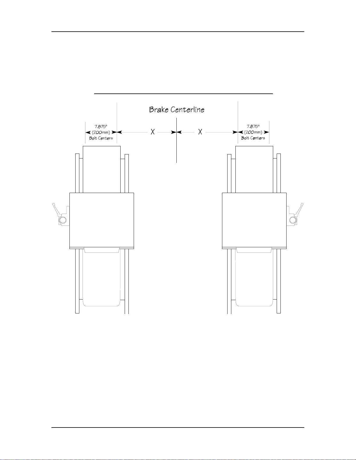
Installation Manual
Mounting Dimensions for Dual Gauges
Refer to the X Dimension tables in the previous section and the
appropriate figure below to determine the location for dual gauges.
S8 Gauges on Hydraulic/Mechanical and Upacting Press Brakes
Figure 2-24. S8 Mounting Dimensions—Hydraulic/Mechanical and Upacting Press Brake
2-32 Revision E Hurco
Page 72
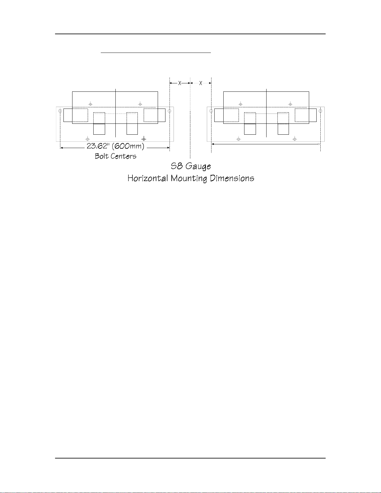
S8 Gauges on Komatsu Press Brakes
Figure 2-25. S8 Mounting Dimensions—Komatsu Press Brake
Installation
Autobend 6 November, 1999 2-33
Page 73
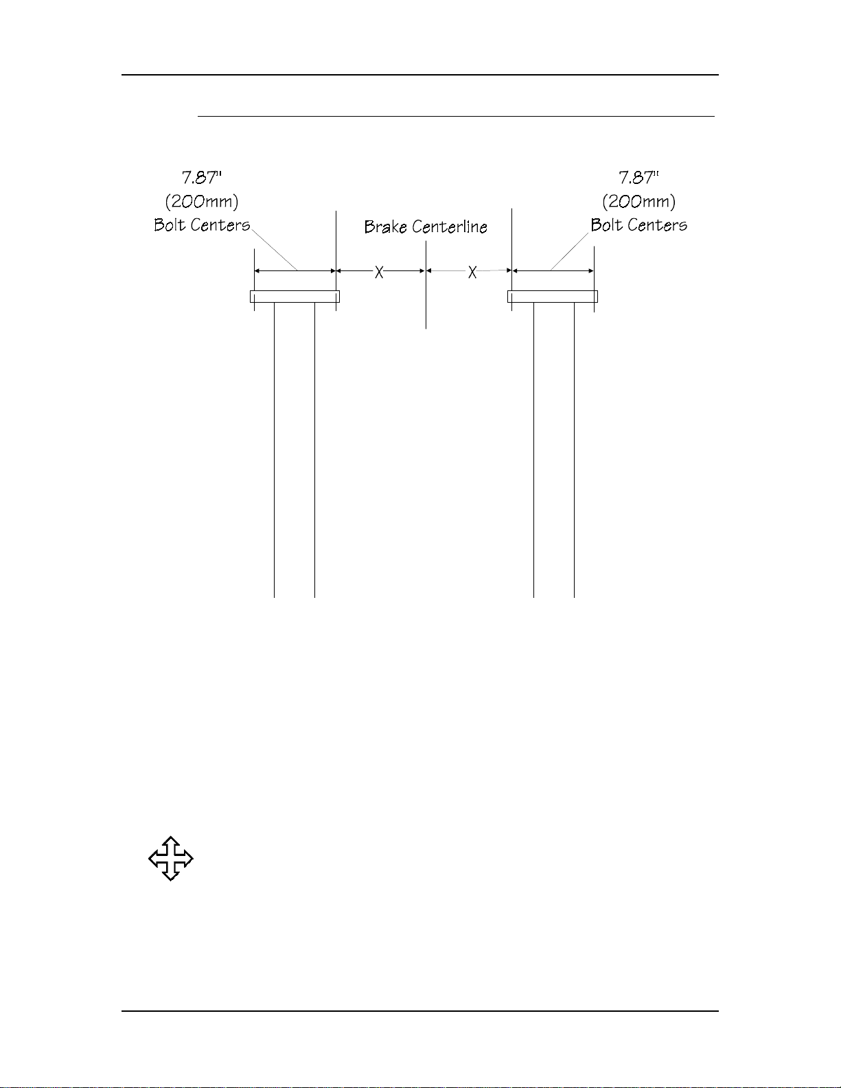
Installation Manual
LP21, LP22, LP22/54 Gauges—Hydraulic/Mechanical, Upacting Press Brakes
Figure 2-26. LP21 and LP22 Mounting Dimensions—Hydraulic/Mechanical
and Upacting Press Brake
Where can we go from here?
Proceed to the “Attaching Gauge to Press Brake” section of this
manual.
2-34 Revision E Hurco
Page 74
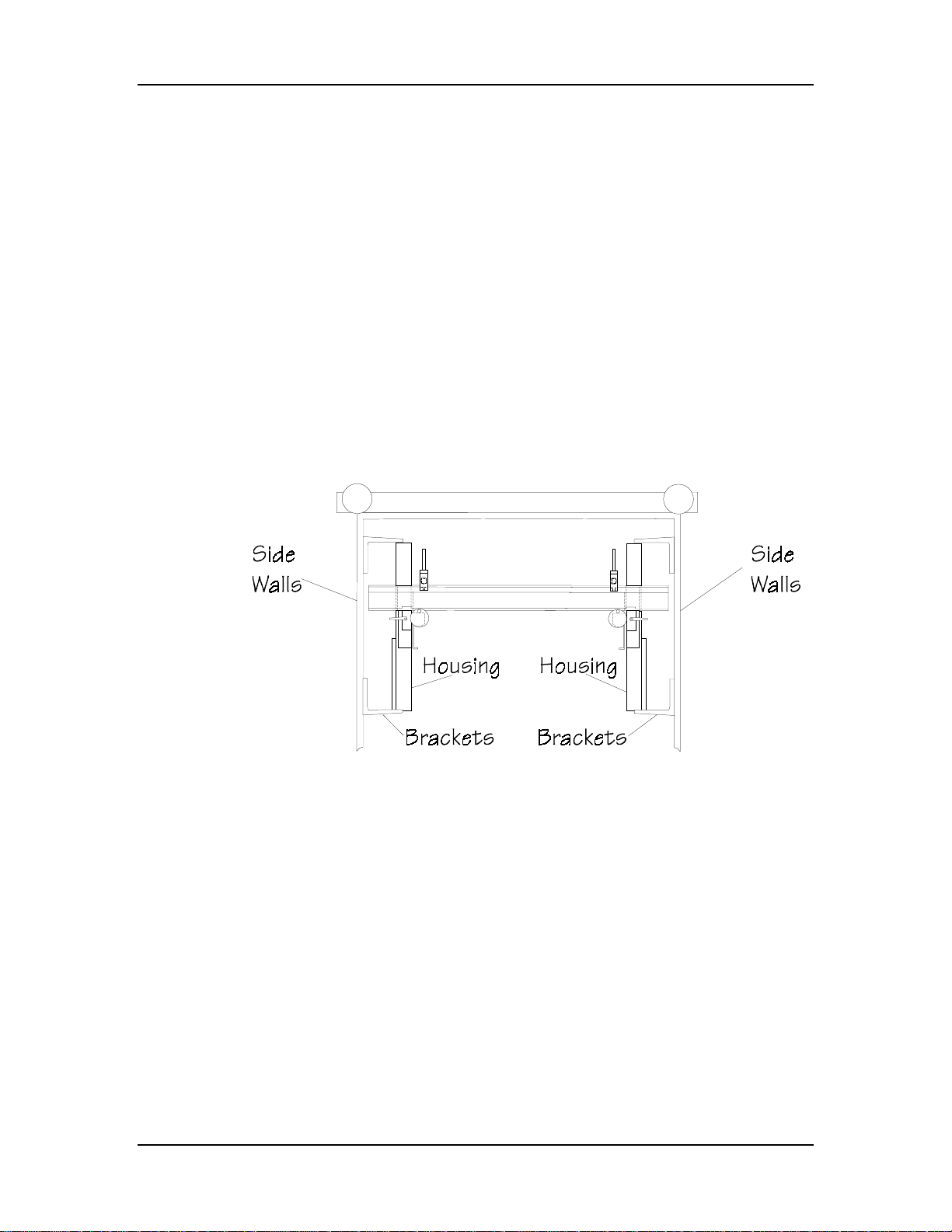
Installation
Vertical Mounting for S8 Gauges
For vertical installation of the S8 gauge, use mounting brackets to attach
the dual housing assemblies to the inner surface of the press brake’s side
walls. Each gauge uses two brackets, one attached to each end. To ensure
the best performance and reliability, align these brackets parallel to the top
of the press bed. Before drilling the mounting holes, position the gauge at
a height so the gauge bar can be vertically adjusted to fit different die
heights.
Follow these instructions to vertically mount S8 gauges:
1. Scribe a horizontal line on both side frames using the top of
the press bed as a basic reference point. Using a plumb and
level, extend this line the full length of the side frame.
Figure 2-27. Top View of Vertical S8 Gauge
Autobend 6 November, 1999 2-35
Page 75
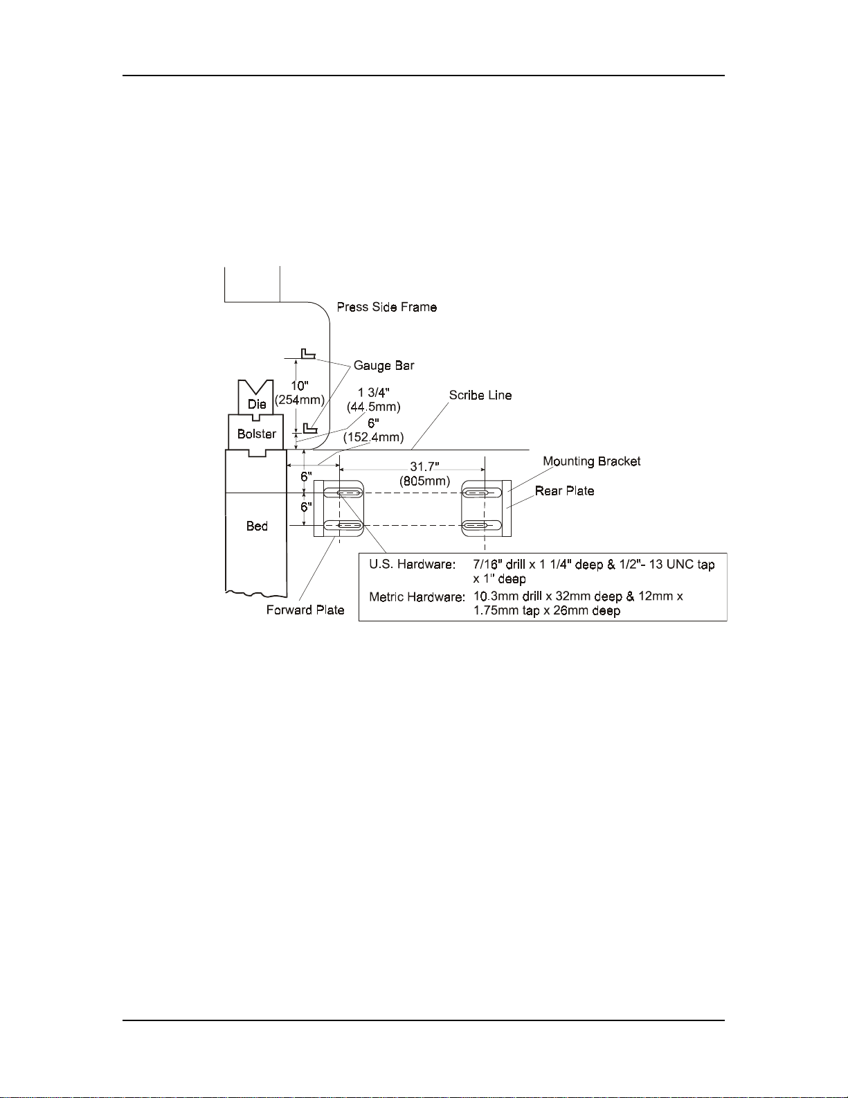
Installation Manual
2. Locate the centerline of both the forward and rear mounting
brackets’ holes (see the figure below). Mark the centers of
the mounting holes.
3. Carefully drill and tap the eight bolt holes to the
recommended sizes and dimensions (see the figure below).
Figure 2-28. Side View of Typical Press Brake
4. Loosely attach the gauges’ mounting brackets to the side
frames, using the screws and flat washers provided.
5. Remove the Autobend S8 name plates at the rear of each
gauge.
6. To prevent each gauge cable (harness) from becoming
entangled with the lead screw when the gauges are mounted
vertically, secure the cable to the gauge frame with tie wraps.
a. Use the 15/64" drill bit and drill one hole in each gauge
frame for connecting the tie wraps. Each hole should be
located 8" from the rear and 1/2" up from the bottom.
b. Insert the self tapping screws, and attach one tie wrap to
each frame.
2-36 Revision E Hurco
Page 76
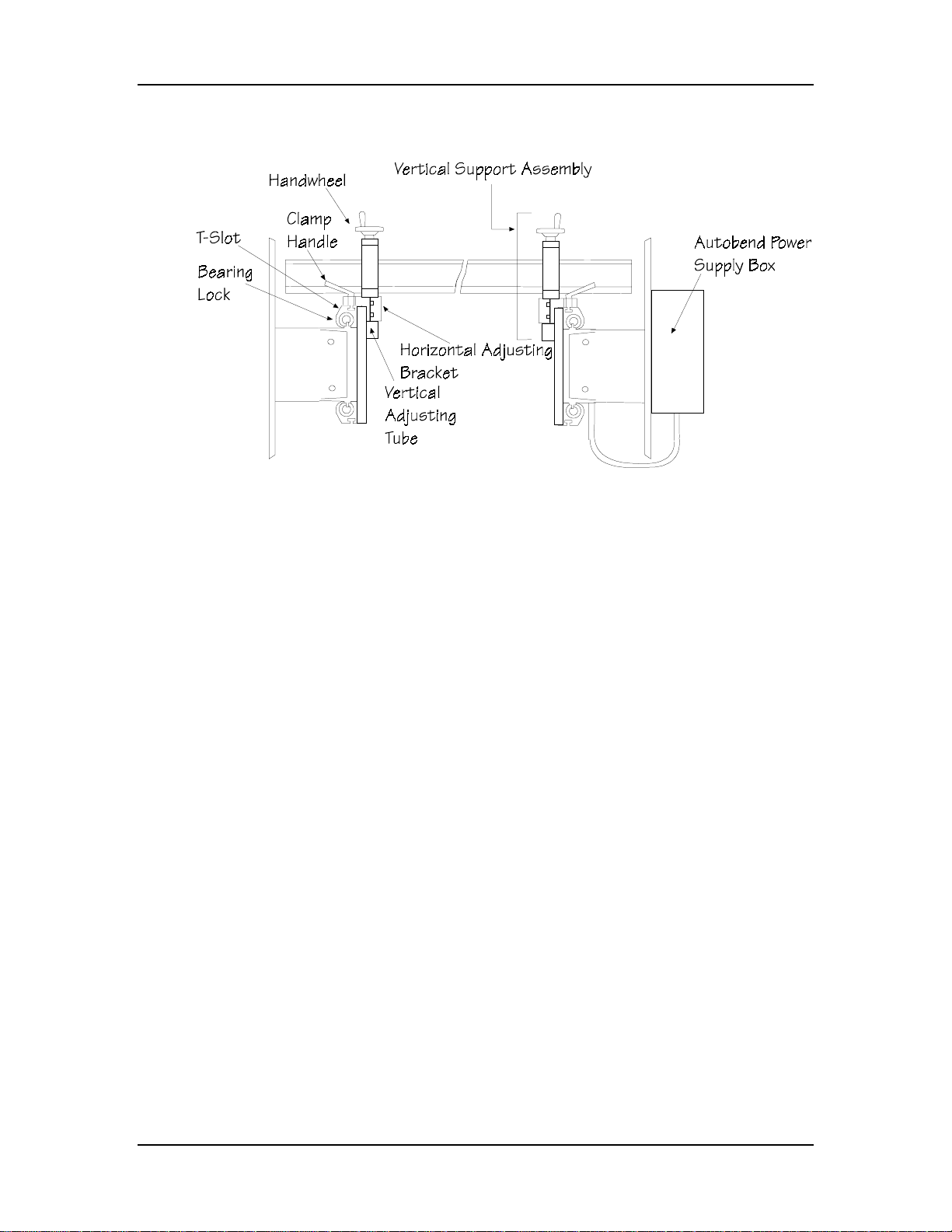
Here is a vertical S8 gauge configuration:
Figure 2-29. Rear View of Vertical S8 Model Gauge
Installation
Autobend 6 November, 1999 2-37
Page 77

Installation Manual
Attaching Gauge to Press Brake
Attach the gauge(s) to the rear of the press brake.
1. Position the gauge(s) to the press and install the mounting
bolts and washers. Tighten the bolts securely against the
washers.
2. Wipe down the lead screw and carriage ways with a soft, lint-
free cloth. Apply a light film of S.A.E. #10 machine oil to the
lead screw and both rod ways.
Note
Hurco and Mebusa press brakes require a spacer plate between the
die retainer plates and each LP21gauge. These spacer plates raise the
gauges so they clear the top of the back cover.
An additional spacer plate is required for inch/metric adjust ment for
an R axis with the LP21 gauge. Alignment between the left and right
sides is critical for proper operation.
Attaching LP21 Rear Cover Kit Assembly
LP21 gauge assemblies consist two sides, a rear connector which attaches
the two sides together, and one motor. Refer to Hurco Part Number 0012010-008/009/010. First mount the two sides, then assemble the rear
connecting shaft, support bearing assemblies, and couplings.
1. Install the rear connecting channel between the two (2)
gauges with four (4) M6 x 16 SHCS and flat washers. Use
the two (2) pre-drilled slots at each end of the channel.
2. Install the rear support bearing into the rear support bearing
housing with the two (2) M5 x 10 BHCS and flat washers in
the side of the housing block.
3. Measure the total distance between the two (2) gear box
shafts that face each other. Cut the rear connecting shaft
1.12" shorter than this measurement.
4. Install the rear support bearing assemblies from above onto
the shaft. Do not tighten the two (2) bearing set screws.
2-38 Revision E Hurco
Page 78

5. Slide one (1) coupling hub onto the end of each of the gear
boxes and connecting shafts.
Figure 2-30. Coupling Hubs
6. Push both gauge carriages as far as possible toward the front
of the press brake to ensure left and right alignment. The
gauges should bottom out on the mounting screws.
7. Center the connecting rod assembly and install inside the
channel by aligning the blocks. Use two (2) M6 x 16 SHCS
to secure blocks. Do not tighten screws .
Important
Installation
Make sure the carriages are evenly aligned.
8. Insert the plastic disks inside the two coupling hubs of the
gear box.
9. Rotate the coupling hub so you can tighten it. The inside
holes should be on top, and the outside holes should be on the
bottom. Make sure the end of the gearbox shaft is flush with
the inboard face of the coupling.
10. Tighten the outside coupling (the top hole).
11. Slide the inside coupling hub to engage the plastic disk on the
outside coupling hub.
12. Tighten the bottom hole on the inside coupling hub.
13. Tighten the bearing support housing block’s screws.
14. Test before installing the covers. Operate with the control to
ensure the left and right gauges are the same distance from
the die.
Autobend 6 November, 1999 2-39
Page 79

Installation Manual
15. Install the covers:
a. Right rear connecting cover — use two (2) M6 x 16
BHCS and flat washers.
b. Left rear connecting cover — use two (2) M6 x 16
BHCS and flat washers.
c. Center rear connecting cover — use two (2) M6 x
16 BHCS and flat washers.
d. Rear Cover strap — use four (4) M6 x 16 BHCS
and flat washers (2 with washers in back and 2 with
washers and nuts).
2-40 Revision E Hurco
Page 80

Attaching Adjustable Leg Assembly for LP22/54 Gauges
The length of the LP22/54 gauges requires leg assemblies for support.
Follow these steps to attach the legs:
1. Make sure the gauge is level front to back.
2. Attach the LP22/54 gauges to the adjustable leg assemblies
with the bolts provided.
3. Secure the adjustable leg assemblies to the floor in a safe
manner.
Note
Hurco cannot provide hardware for securing the leg assembly to the
floor since floor types vary.
Installation
Where can we go from here?
• Consult the “Maintenance” chapter for maintenance
procedures.
• Proceed to the “Gauge Bar and Mounting Devices” section of
this chapter.
Autobend 6 November, 1999 2-41
Page 81
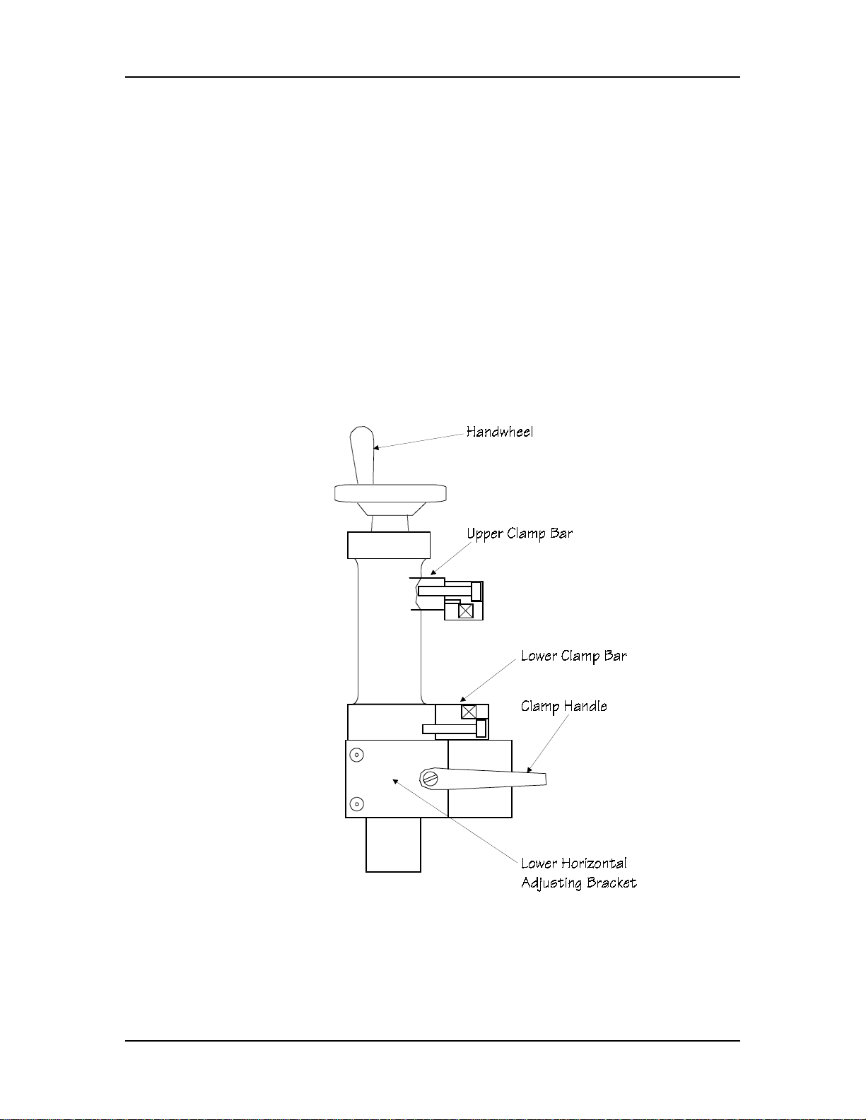
Installation Manual
Gauge Bars and Mounting Devices
Following are instructions for installing different types of gauge bars to the
gauge with vertical supports.
Vertical Supports
Vertical supports are manually adjusted so the gauge bar can produce
different bends. The handwheel allows approximately three inches of fine
vertical adjustment. Use the lower horizontal adjusting bracket to make
coarse vertical movements. A T-slot in the gauge bearing block provides
horizontal movement relative to the tooling.
Here is a vertical support for S6, S7, or S8 gauges:
Figure 2-33. S6, S7, and S8 Vertical Support Assembly
2-42 Revision E Hurco
Page 82

Installation
S6, S7, S8, and Vertical S8 Gauges
Follow these steps to install vertical supports to S6, S7, and S8 gauge bars:
1. Adjust both vertical supports to the same length.
2. Placing the clamp handle and T-nut to the rear, slide the
vertical supports an equal distance into the T slot in the
bearing blocks.
3. Tighten the clamp handle slightly when in position.
Where can we go from here?
Proceed to either the “Y-Shaped Rigid Gauge Bar” or “Tilting Gauge
Bar” section of this chapter.
Autobend 6 November, 1999 2-43
Page 83
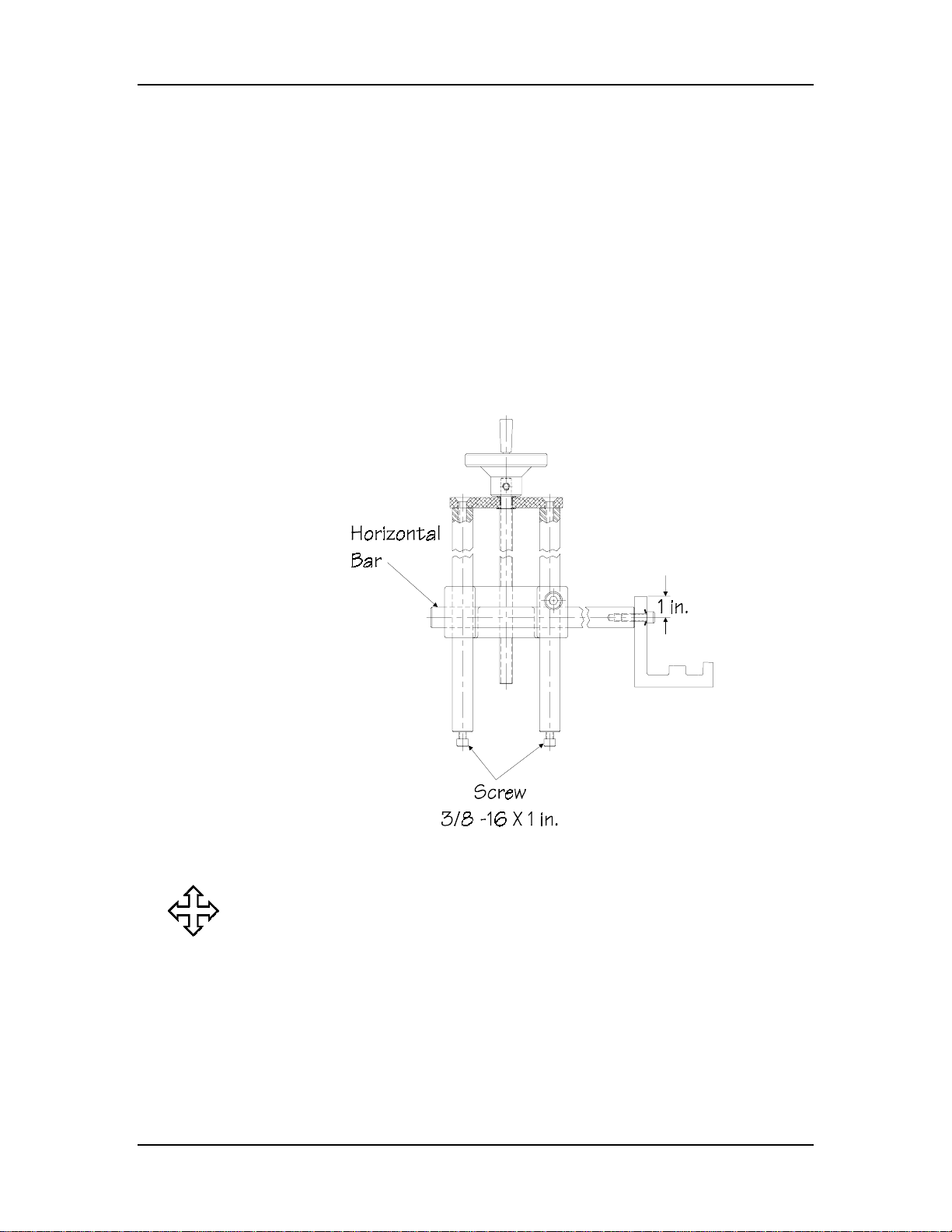
Installation Manual
LP11, LP21, and LP22 Gauges
Install vertical supports to LP11 and LP22 gauge bars as follows:
Here is a vertical support for LP11, LP21, or LP22 gauges:
1. Remove the two (2) 3/8"–16 × 1 SHCS from the bottom of
the support assembly.
2. Insert the vertical supports into the corresponding sockets on
the outside of the gauge carriage. Also, keep the horizontal
bar on the outside of the supports.
3. Re-install the two screws and tighten.
Figure 2-34. LP11, LP21, and LP22 Gauge Bar and Vertical Supports
Where can we go from here?
Proceed to the “LP11 and LP22 Gauge Bar” section of this chapter.
2-44 Revision E Hurco
Page 84
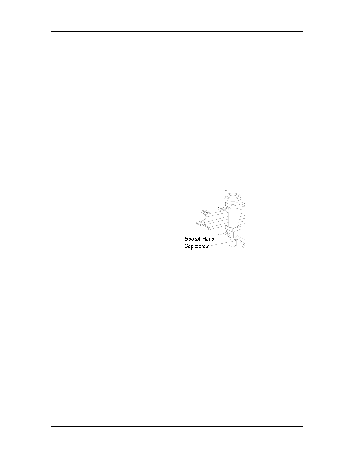
Gauge Bars
Installation
The Autobend utilizes three types of gauge bars: the Y-Shaped Rigid
Gauge Bar, the Tilting Gauge Bar, and the LP11, LP21, and LP22 Gauge
Bar. Following are instructions for installing each type.
Y-Shaped Rigid Gauge Bar
The Y-Shaped Rigid Gauge Bar is installed on Autobend’s S6, S7, and S8
gauges. Vertical supports hold it to the gauge. This type of gauge bar
provides an accurate positive stop for the material being bent. Flip fingers
installed on the gauge bar provide clearance for the material as it is bent.
To install the Y-Shaped Rigid Gauge Bar, follow these instructions:
1. Loosen the socket head cap screws of the upper and lower
clamp bars located on the vertical supports (see the figure
below).
Figure 2-35. Position of Gauge Bar and Vertical Supports
2. Insert compression springs into the cavities of both the lower
and upper clamp bars. See the figure on the following page.
3. Install the lower clamp bars with just a few turns of the
screws.
4. Position the Y-shaped gauge bar into the lower clamp bars
and tighten slightly.
5. Install the upper clamp bars and compression springs,
tightening slightly.
6. Using a level, check the gauge surface and make any
necessary adjustments to position the gauge bar both
vertically and horizontally.
7. Tighten the upper and lower clamp bars securely.
Autobend 6 November, 1999 2-45
Page 85
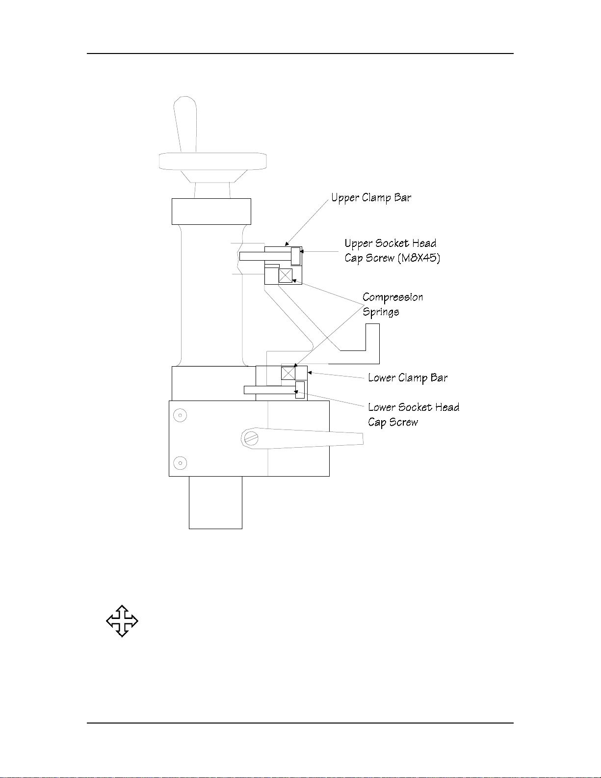
Installation Manual
Refer to the figure below when installing a Y-Shaped Rigid Gauge Bar:
Figure 2-36. Vertical Support and Y-Shaped Rigid Gauge Bar
Where can we go from here?
Proceed to the “Carriage Arrestor Bar” section of this chapter.
2-46 Revision E Hurco
Page 86
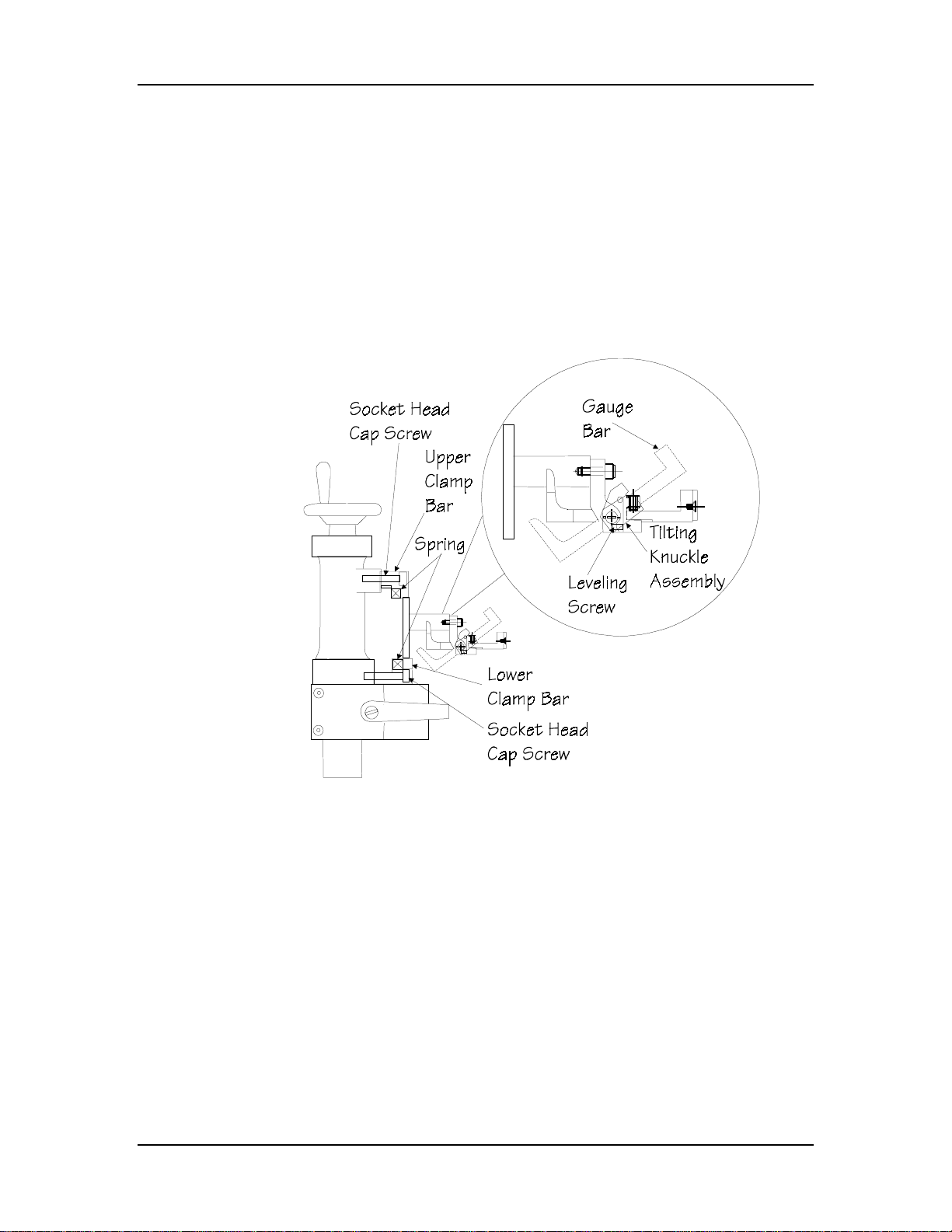
Installation
Tilting Gauge Bar
The Tilting Gauge Bar is installed on Autobend’s S6, S7, and S8 gauges.
Steel wear plates on the front of the aluminum gauge bar protect it from
the metal being formed as they make contact. Vertical supports hold the
bar to the gauge. This type of gauge bar pivots; the tilting action provides
clearance for the material as it is bent.
1. Loosen the socket head cap screws of the upper and lower
clamp bars located on the vertical supports (see the figure
below).
Figure 2-37. Vertical Support and Tilting Gauge Bar
2. Insert compression springs into the cavities of both the lower
and upper clamp bars.
3. Install the lower clamp bars with a few turns of the screws.
4. Position the tilting knuckle assemblies into the lower clamp
bars and tighten slightly.
5. Install the upper clamp bars and compression springs,
tightening slightly.
Autobend 6 November, 1999 2-47
Page 87

Installation Manual
6. Position the gauge bar into the tilting clamps, tightening the
set screws to hold the bar into position. Verify that after the
bar tilts it returns to a level position. Adjust the leveling
screw as necessary to maintain this movement.
7. Tighten all cap screws.
Where can we go from here?
Proceed to the “Carriage Arrestor Bar” section of this chapter.
2-48 Revision E Hurco
Page 88
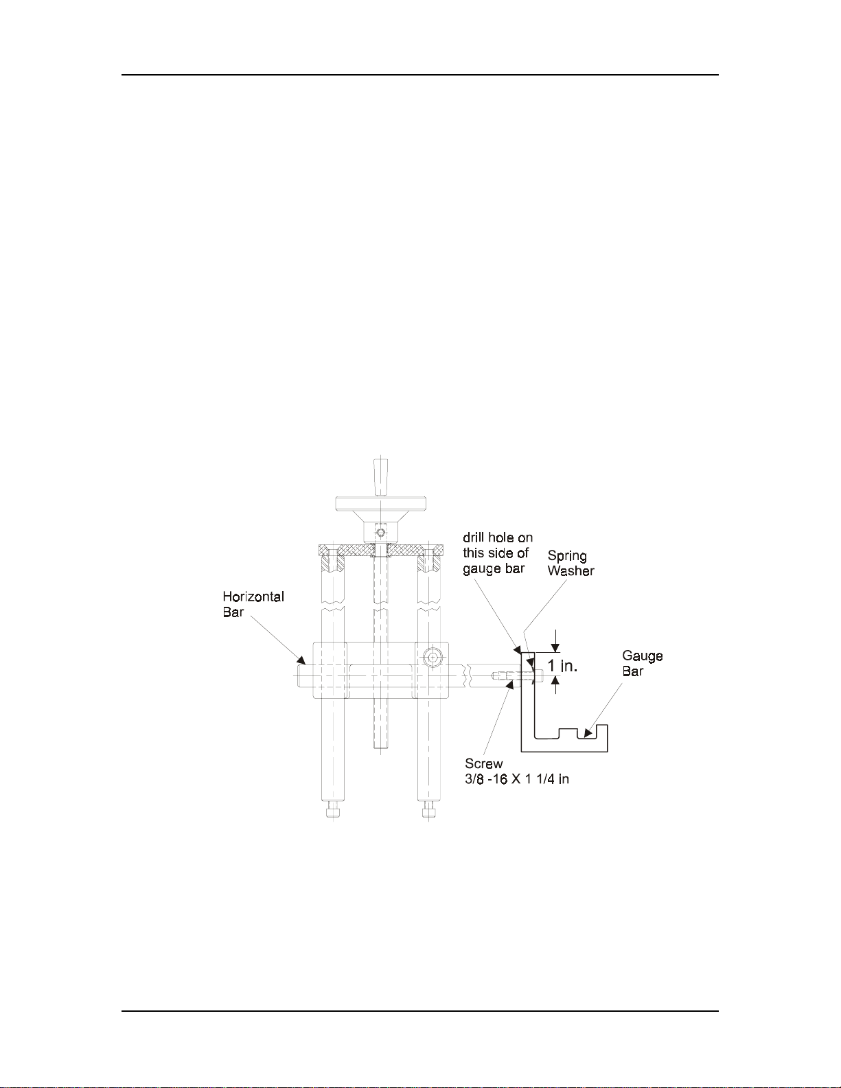
Installation
LP11, LP21, and LP22 Gauge Bar
The LP11, LP21, and LP22 gauge bar is installed on Autobend’s LP
gauges. Vertical supports hold the bar to the gauge. Follow the procedures
below to install these gauge bars:
1. Measure the distance between the horizontal shafts on the
two LP series vertical supports.
2. Record the distance.
3. Transfer the measurement to the back of the gauge bar. Keep
the beginning and end points of the measurement centered on
the bar.
4. Drill one (1) 7/16" hole at each end 1" from the top rear of
the gauge bar. See the figure below.
5. Mount the bar.
6. Tighten the cap screws and spring washers.
Figure 2-38. LP11, LP21, and LP22 Gauge Bar and Vertical Supports
Autobend 6 November, 1999 2-49
Page 89
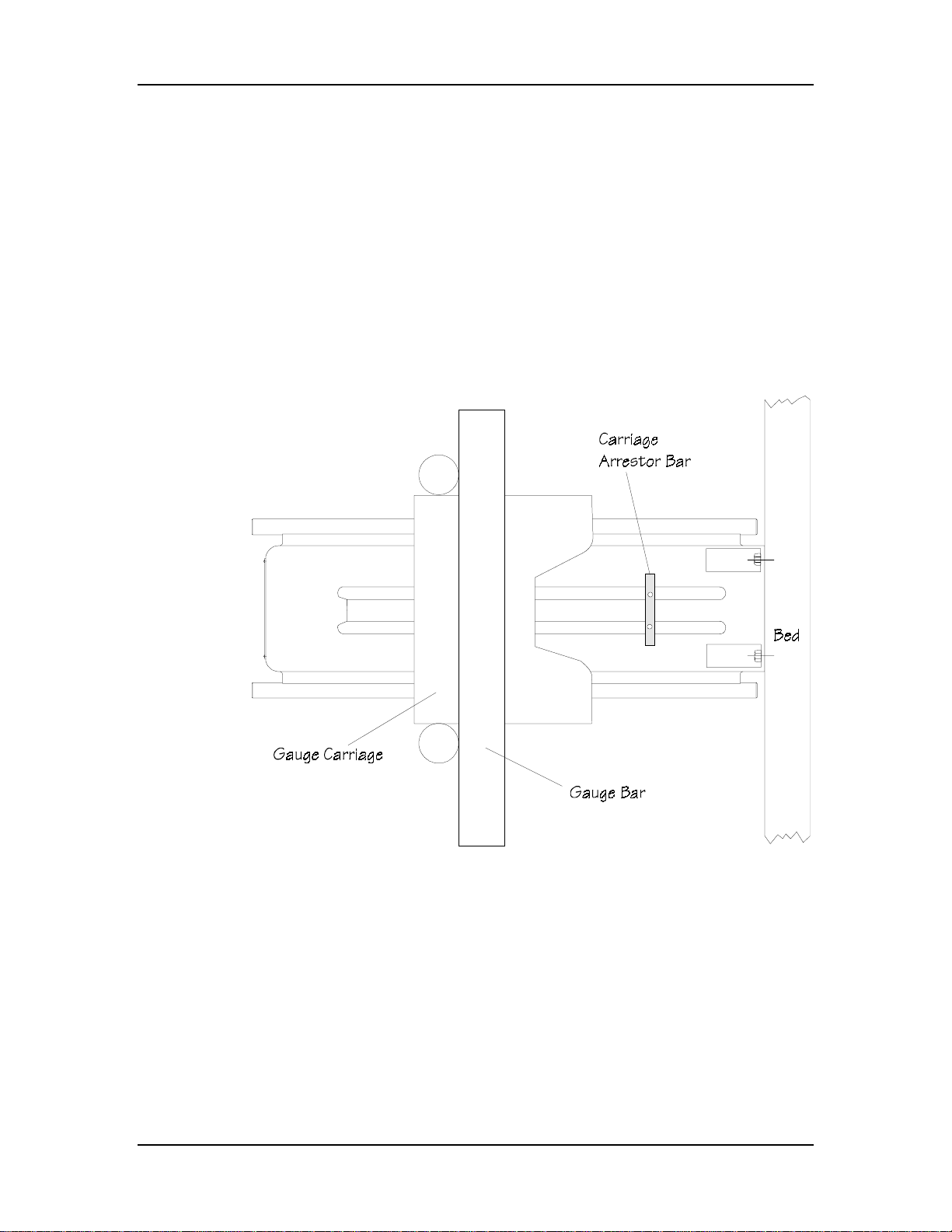
Installation Manual
Carriage Arrestor Bars
Use carriage arrestor bars for safety devices. They consist of two plates
that clamp to each gauge frame and provide a forward positive hard stop
for the carriage. Place each arrestor bar at a point that prevents t he gauging
surface from interfering with the forming tools. Set them in the correct
position each time after a tooling change and/or re-referencing the gauge
bar.
Refer to the figure below for the S6 or S8 gauge.
Figure 2-39. Carriage Arrestor Bar on S6 or one S8 Gauge
2-50 Revision E Hurco
Page 90
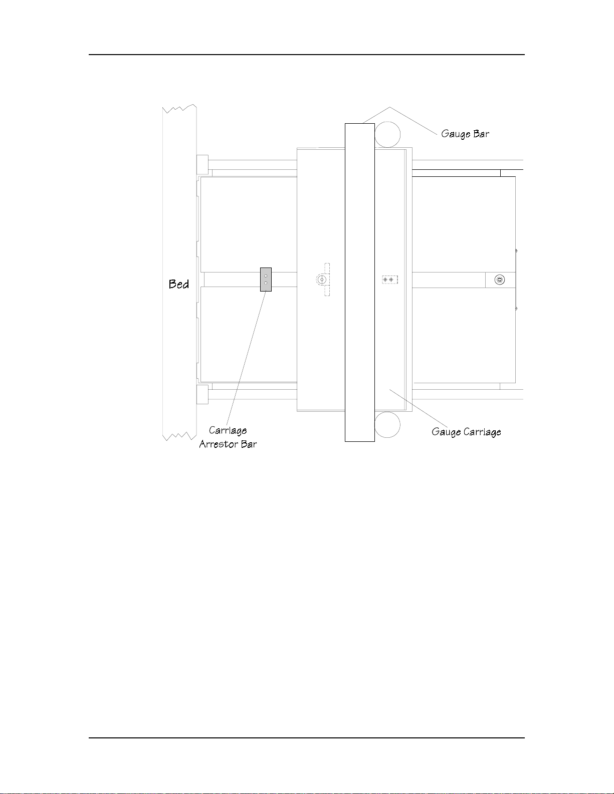
Refer to the figure below for the S7 gauge.
Installation
Figure 2-40. Carriage Arrestor Bar on S7 Gauge
Autobend 6 November, 1999 2-51
Page 91
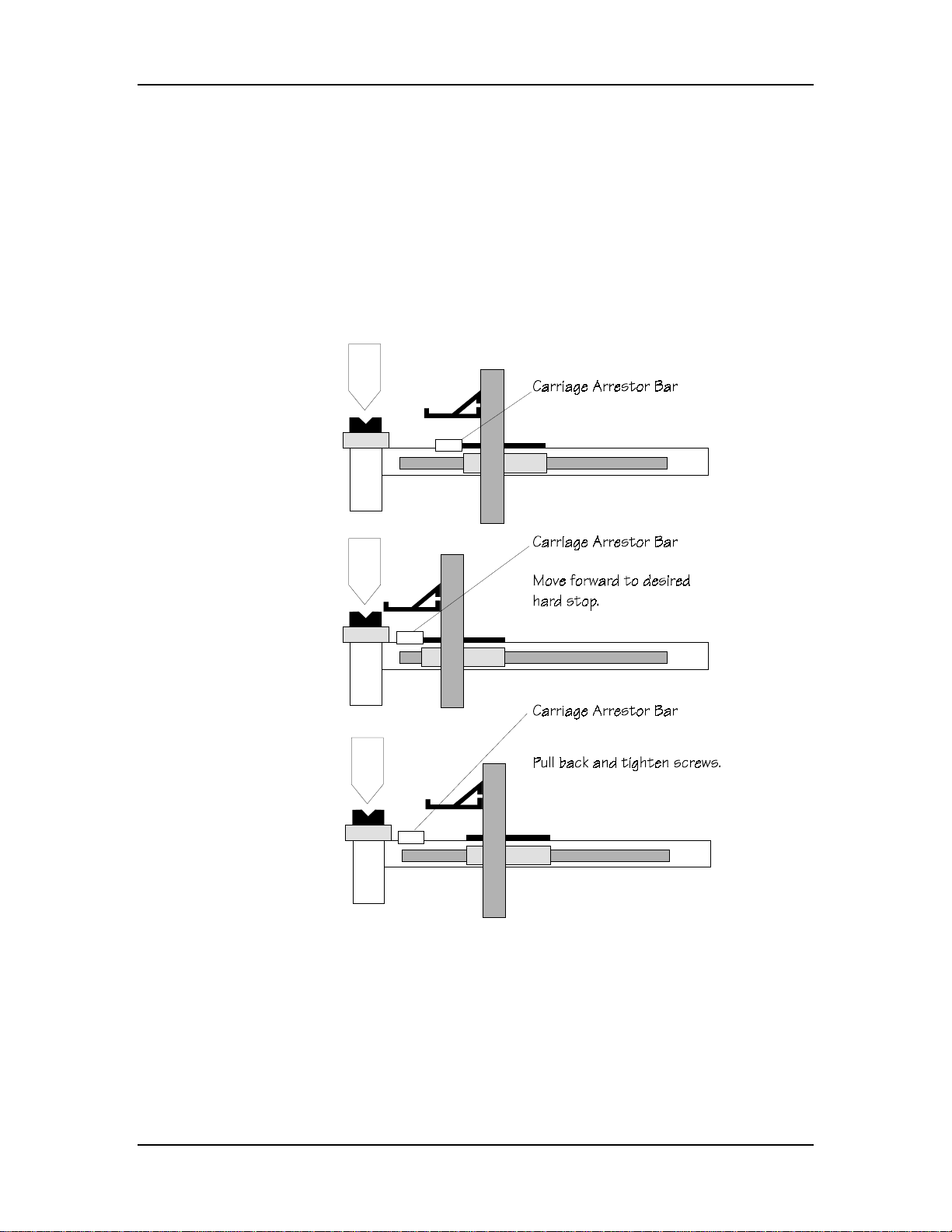
Installation Manual
Follow these instructions to install the carriage arrestor bars:
1. Remove the screws from the carriage arrestor bars and
separate the clamp into two pieces.
2. Sandwich the clamp plates around the gauge, replace the
screws, and tighten them until the clamp just slides.
3. Set the final position by sliding the gauge carriage forward to
the desired hard stop position.
Figure 2-41. Side View of Press Brake and Gauge Bar with Carriage Arrestor Bar
4. Pull the gauge carriage back to expose the carriage arrestor
bars.
5. Tighten the screws to lock the carriage arrestor bars.
2-52 Revision E Hurco
Page 92
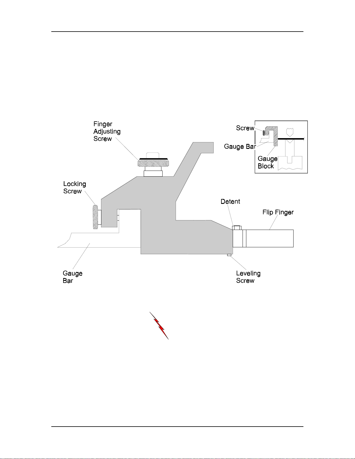
Selecting the Gauging Surface
The Autobend gauge bar provides various methods of referencing the
material to be formed. For best results do not place material directly
against the front edge or face of the gauge bar. This surface should be used
to hold the flip fingers and gauge blocks suited to this task. Ideally using
two stops per bend is recommended since tooling centerlines and material
edges are typically not straight.
Installation
Figure 2-42. Flip Fingers and Gauge Block
Warning
Ensure that the carriage arrestor bars are correctly set
on the gauge(s) to prevent any part of the gauge bar,
finger(s) or block(s) from contacting the tooling in an
unsafe manner. All adjustments should be made from
the rear of the press brake. Do not reach across the
tooling or in through the bed and ram.
Autobend 6 November, 1999 2-53
Page 93

Installation Manual
Flip Fingers
Flip fingers permit closer gauge positioning to the tooling. The fingers’
tilting action allows reverse bending, with the length of the reverse bend
dependent on the type of part to be formed.
Fingers can be manufactured by customers to suit their individual forming
needs. For the most accurate results, always reference the fli p fingers prior
to using them after changing the tooling setup. Refer to the “Referencing
the Gauging Surface” section that follows.
Install the flip fingers at any location along the gauge bar to best suit the
requirements of the part. These fingers allow approximately 0.090" of
horizontal micro-adjustment for close-tolerance forming. Fingers rotate in
90° increments for narrow or wide target area selection. Each finger tilts
on a leveling adjustment screw at the front bottom of the body. The
locking screw at the end of the flip finger assembly is used to lock it in
place along the gauge bar.
When two flip fingers are used, both must be set to the same length, as
measured from the back of the body to the tip of the finger. Otherwise, the
parts will not have equal flange lengths on both ends.
Gauge Blocks
Gauge blocks provide a large target area suited for work involving largescale parts and long flanges.
Install gauge blocks at any location along the gauge bar to best suit the
requirements of the part. The locking screw at the end of the gauge block
is used to lock the block in place on the gauge bar. For the most accurat e
results, always reference the gauge blocks prior to using them after
changing the tooling setup. Refer to the “Referencing the Gauging
Surface” section that follows.
2-54 Revision E Hurco
Page 94
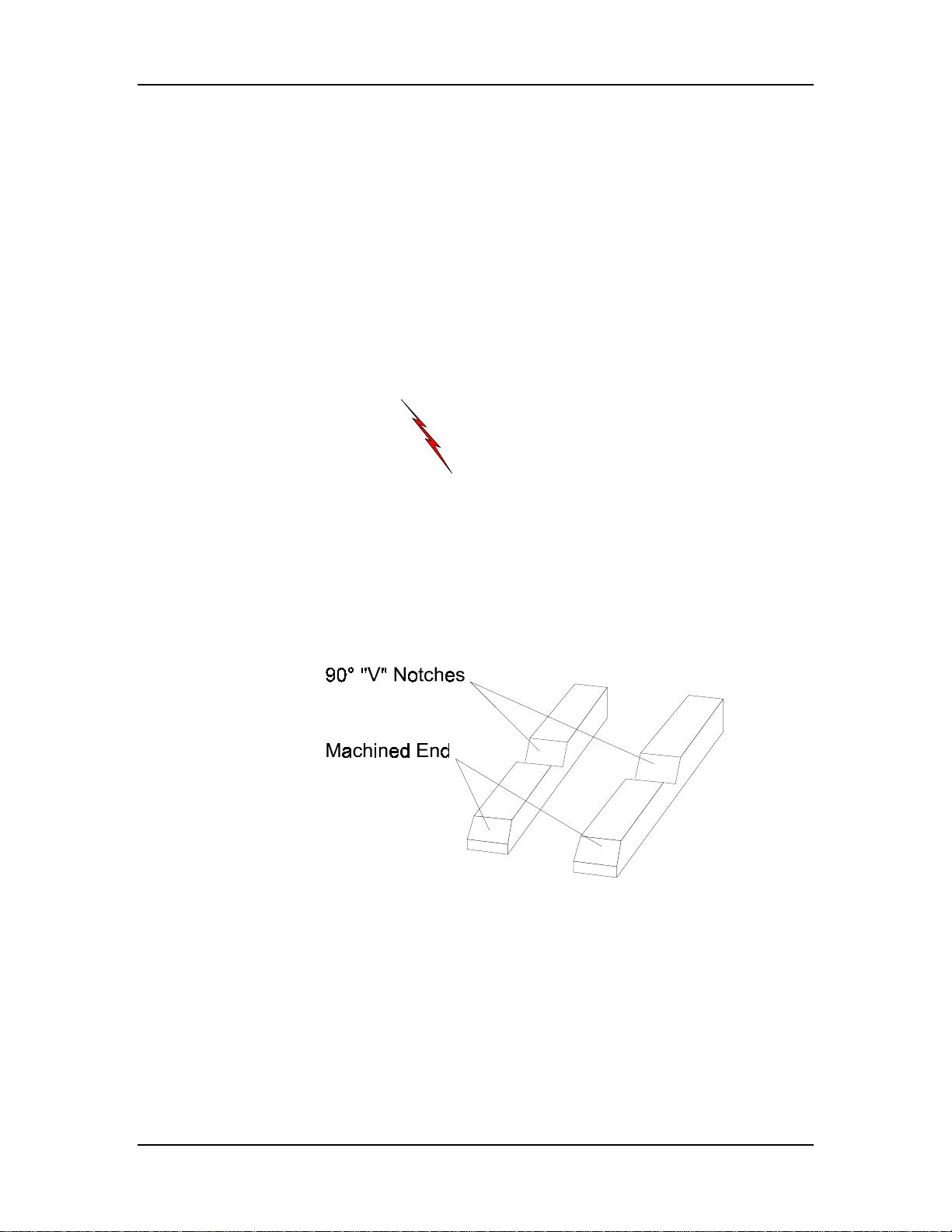
Referencing the Gauging Surface
Prior to forming parts, the gauging surface must be referenced to the
forming tools. The programmed dimension is the distance from the
gauging surface to the punch centerline. This centerline changes for each
set of tooling.
Two zero reference bars are provided with each Autobend to provide a
quick and controlled method of squaring the gauge bar. Each zero
reference bar has a 90° “V” notch in the center and a machi ned edge on
one end. The distance from the center of the “V” notch to the machined
edge is 5" (127 mm).
Warning
Do not use the reference bars if the rubber pad is
damaged or missing. This pad is a safety feature to
reduce the possibility of breakage from slight overpressure. The pads will not prevent the bars from
breaking in the event of severe over-pressure from the
press brake.
Installation
Figure 2-43. Zero Reference bars
Autobend 6 November, 1999 2-55
Page 95

Installation Manual
Follow these instructions to reference the gauge bar:
Important
For AB6 systems equipped with Ram control, the Ram On key’s
LED should be off indicating the control is in Standby mode.
1. Place the flip fingers or gauge blocks on the gauge bars at the
extreme ends of the tooling to ensure that the gauge bar is
parallel to the tooling.
2. Loosen the clamp bolts on the lower part of the vertical
supports. Slightly pull back the support.
3. Loosen the carriage arrestor bars.
4. Program a single bend job with a 5" (127 mm) dimension and
0 bend allowance.
Note
Refer to the “Job Programming” and “Bend Programming” sections
of the AB6 Programming and Operations manual for more
information.
5. Press the Run button.
6. Insert the zero reference bars so the machined edges face the
gauging surface with the “V” notches aligning with the punch
centerline.
7. Carefully jog the ram until the tooling firmly clamps the zero
reference bars. Lock the ram in this position.
8. Adjust the gauge bar’s height so the gauging surface is
aligned with the reference bars.
9. Push the vertical supports forward so the gauging surface is
flush against the zero reference bars. For the most accurate
results, use a 0.002" feeler gauge to verify that the gauge
surface is flush with the machined edge of the zero reference
bars.
10. Lock the clamping bolts at the bottom of the vertical
supports.
11. Return the ram to its open position. Remove the zero
reference bars and store them in a safe place.
12. Press the console’s Stop button.
2-56 Revision E Hurco
Page 96
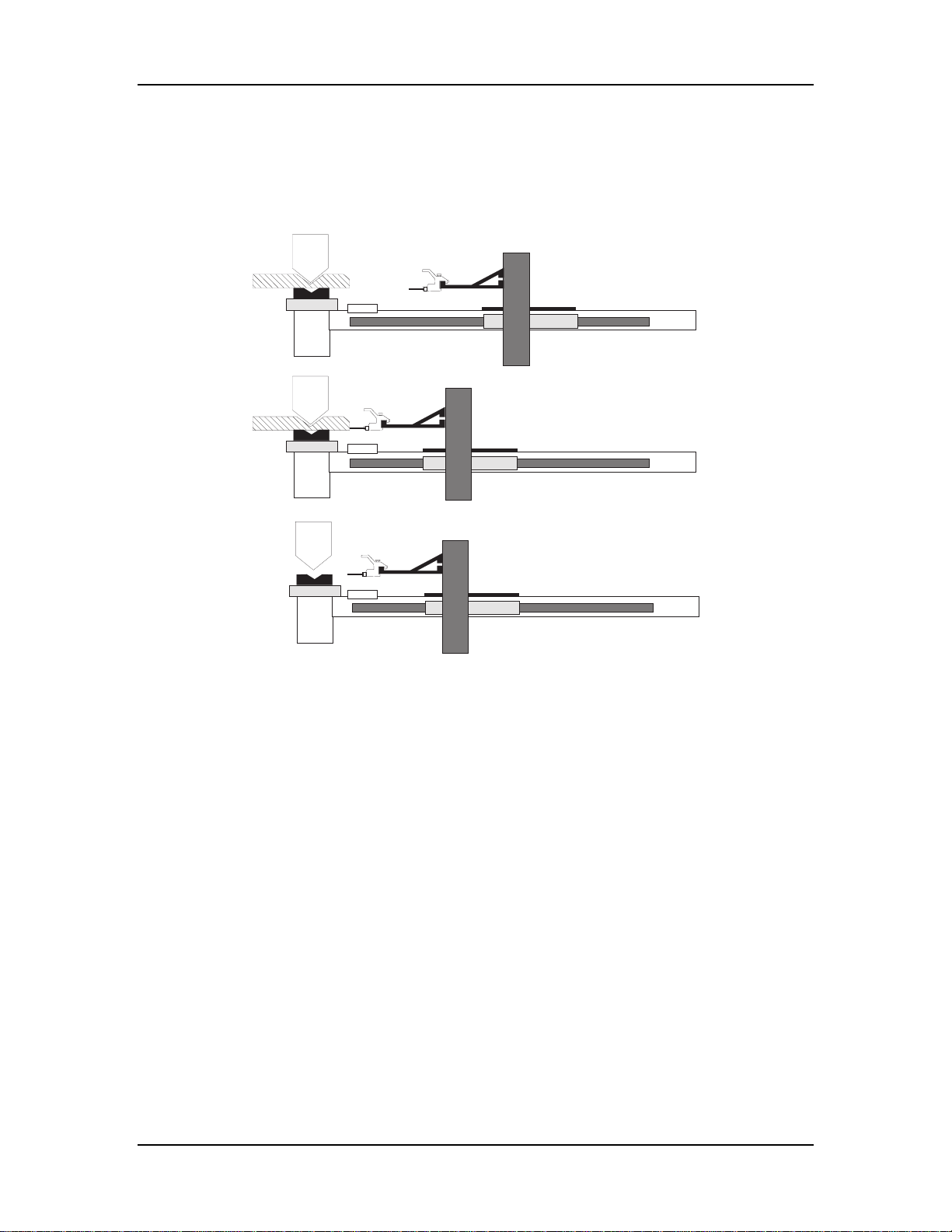
13. Return the Y-Axis mode to Active.
14. Press the Ram On key.
The figure below illustrates the gauge referencing process:
Installation
Figure 2-44. Gauge referencing
Autobend 6 November, 1999 2-57
Page 97
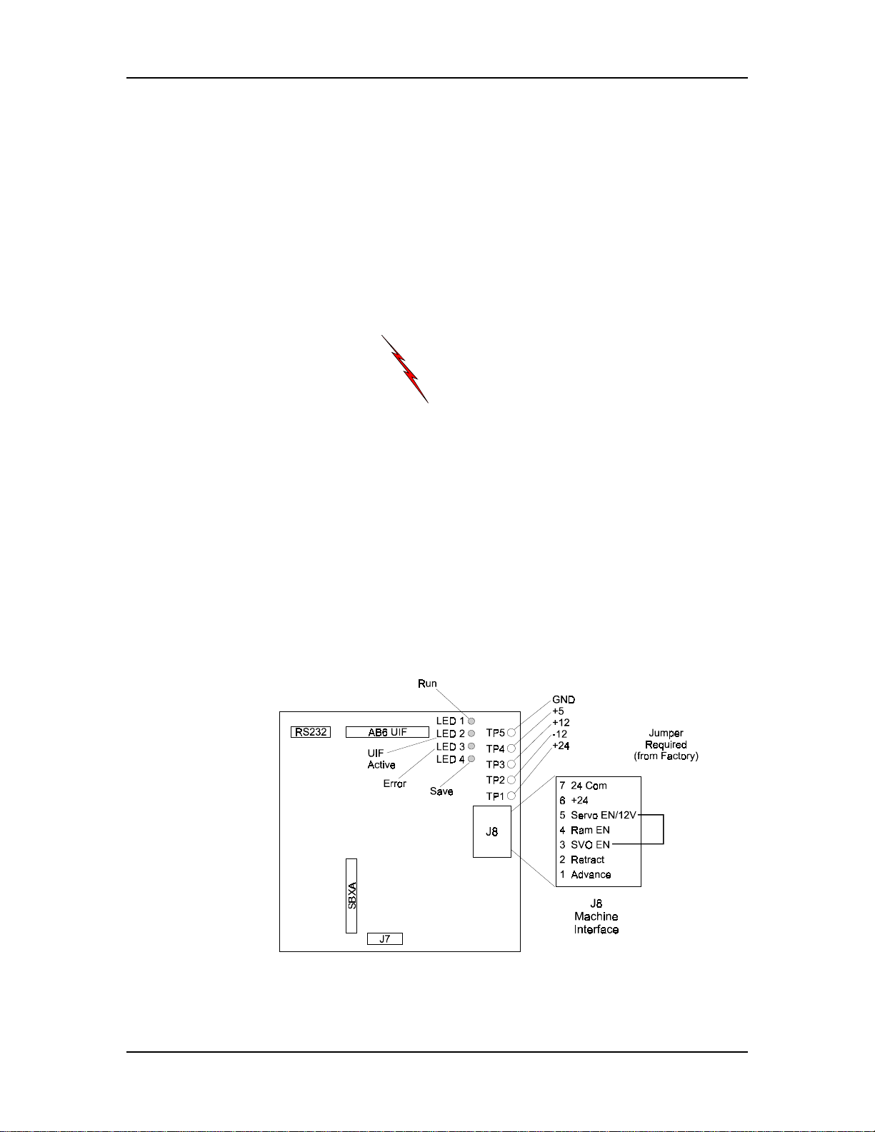
Installation Manual
Electrical Connections
Electrical connections for the AB6 are covered in this section. These
connections include the advance and retract sensor. There are also cable
connections between the power cabinet, control console, and gauge(s).
Two types of power cabinets are available for the AB6: the Small or
Standard power cabinets which have a Main board for advance retract
connections, and the Large power cabinet which contains a Relay board
for advance retract connections.
Before performing any electrical connections, become
familiar with the “Electrical Safety Guidelines” in the
“Introduction” chapter of this manual.
Warning
Small or Standard Power Cabinets with Main Board
The electrical connections require stripped wires to be inserted into the J 8
connector in the Main Board. The following sections refer to the Main
Board J8 Connector. This removable 7-pin connector is located on the
Main board in the AB6 Small or Standard power cabinet (see the figure
below). This figure shows the Main board’s components.
Figure 2-45. Main Board with J8 Connector
2-58 Revision E Hurco
Page 98

J8 Connector
Make connections to the J8 connector as follows:
1. Remove the J8 connector from the Main board.
2. Open a terminal by inserting the blade of a small flat
screwdriver into the rectangular slot above the wire
connection point as shown in the figure below.
3. As the directions in the following text require, insert the
stripped wire into the circular hole directly below the
appropriate rectangular slot. Be sure that the jaws do not
pinch the wire insulation.
4. Remove the screwdriver. Gently pull on the wires to ensure
they are securely set in the connector.
5. Repeat these steps for each wire connection.
Installation
Figure 2-46. Inserting Wires into a J8 Connector
Advance Connections
There are different types of connections to advance the gauge. These
connections are made with a shielded cable that runs between the advance
and the AB6 power cabinet.
The advance switch signals the gauge to advance to its next programmed
station on mechanical and upacting press brakes. However, for Guifil and
Adira upacting press brakes the advance cable is connected without using
the advance switch. An external advance relay provides a direct
connection to its upper limit switch for hydraulic press brakes.
For more specific connection information, read the press brake’s
instructions.
Autobend 6 November, 1999 2-59
Page 99
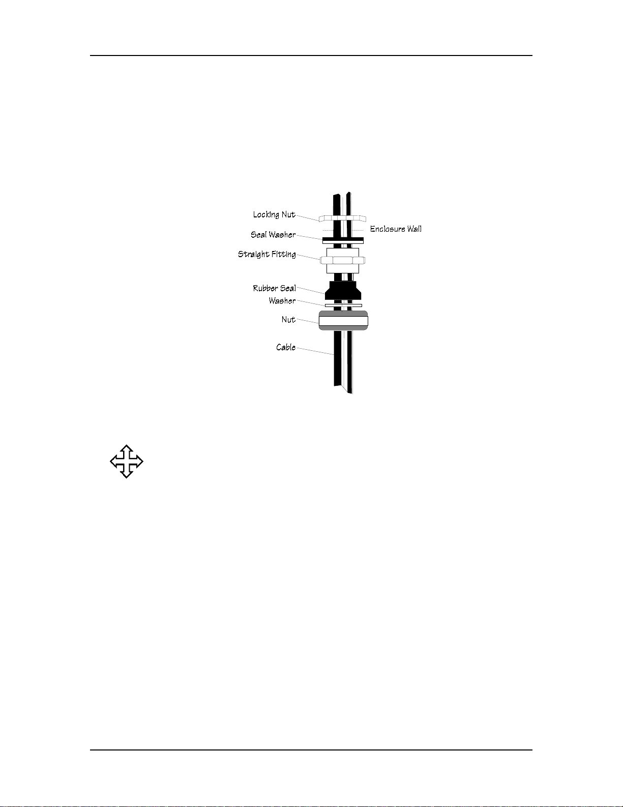
Installation Manual
Two-Conductor Shielded Cable
The following sections refer to a two-conductor shielded cable that
connects the advance switch or relay to the AB6 power cabinet. This cable
enters the bottom of the cabinet through a cord grip conduit fitting. Refer
to the figure below for assembly of the fitting.
Figure 2-47. Cord Grip
Where can we go from here?
The “Advance Switch” section contains directions for installing the
advance switch on mechanical or upacting press brakes (except
Adira and Guifil).
Or...
The “Advance Cable” section contains directions for connecting the
advance cable on Guifil and Adira upacting press brakes.
Or...
The “Advance Relay” section contains directions for installing the
advance switch on hydraulic press brakes.
2-60 Revision E Hurco
Page 100
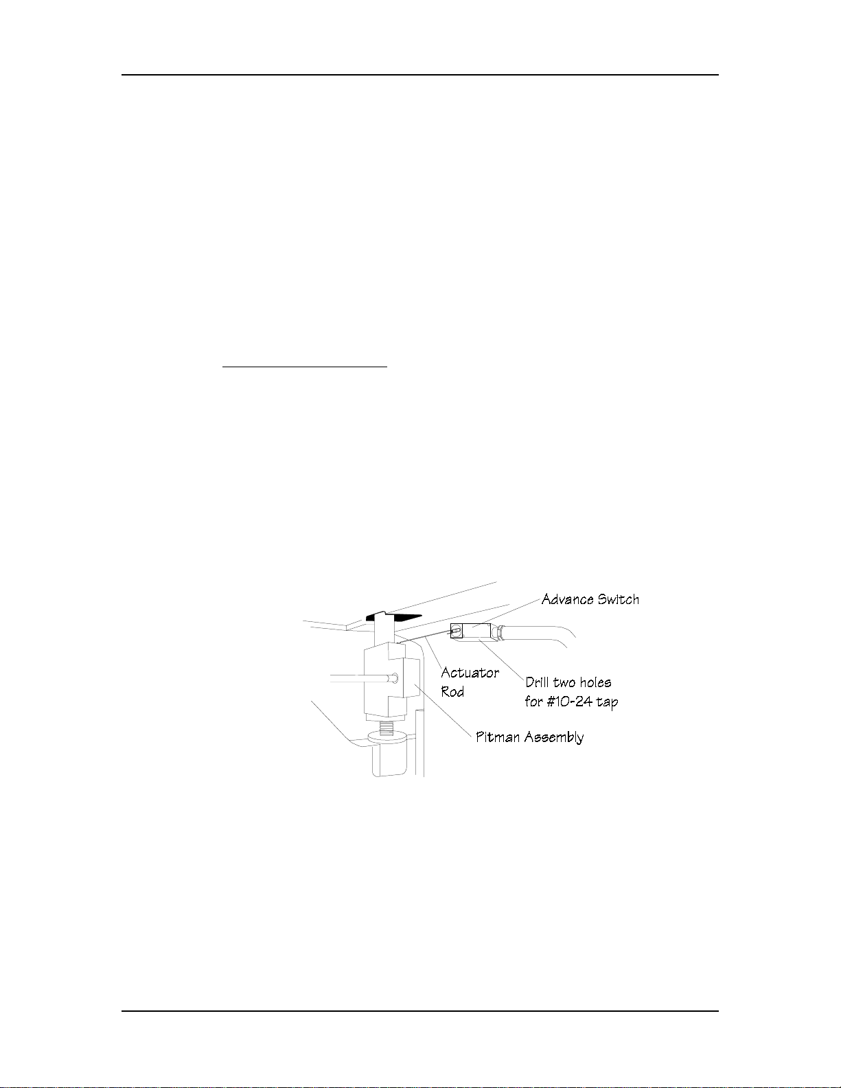
Installation
Advance Switch
Determine a suitable location for mounting the advance switch on the
stationary part of the press brake’s frame for either mechanical or upacting
press brakes.
Locate these materials in the AB6 installation kit:
• two-conductor shielded cable
• two (2) cord-grip conduit fittings sized for the cable
• advance switch and actuator rod
• mounting screws
Mechanical Press Brakes
Mechanical press brakes use an advance switch actuated at the top of the
ram stroke by the Pitman assembly and the rotating shaft to signal the
gauge to advance to its next programmed position.
Do not mount the switch so that any adjustable portion of the ram actuates
it. Mounting the switch in this manner prevents having to adjust the switch
every time the shut-height changes. The switch should close just before the
ram reaches the top of its upward motion and open before the ram
completes its downward stroke.
Figure 2-48. Advance Switch Mounting for Mechanical Press Brakes
Autobend 6 November, 1999 2-61
 Loading...