

Page 1

INSTRUCTIONS FOR USE
DMX / SRX
Digital Handheld Doppler
S/W – V3
772484EN-21 11/2020
Page 2

Contents
1. Safety ........................................................................................ 5
1.1 Warnings ................................................................................................. 5
1.2 Patient Applied Parts ............................................................................. 6
2. Introduction ............................................................................... 7
2.1 Intended Use & Indications ................................................................... 9
2.2 Contraindications .................................................................................. 9
2.3 Battery Requirements............................................................................9
2.4 Unpacking / Preliminary Checks .......................................................... 10
2.5 Service Life ............................................................................................. 10
3. ProductIdentication ............................................................... 11
3.1 Product Controls ....................................................................................11
3.2 SymbolIdentication .............................................................................12
3.3 Display .................................................................................................... 13
3.3.1 Setup Screen..........................................................................................................13
3.3.2 Status Bar...............................................................................................................14
4. Setup........................................................................................... 15
4.1 Battery Insertion / Replacement & Micro SD Card Insertion ............. 15
4.2 Probe Connection .................................................................................. 16
4.3 Setup Screen .......................................................................................... 16
4.3.1 Battery Selection ....................................................................................................17
4.3.2 Date and Time ......................................................................................................17
4.3.3 Brightness ............................................................................................................. 18
4.3.4 Vascular, PPG and Obstetric Setup .......................................................................19
4.4 System Connection ...............................................................................19
5. Operation .................................................................................. 20
5.1 Switching On .......................................................................................... 20
5.2. Vascular Mode ........................................................................................ 20
5.2.1 Vascular Setup .......................................................................................................21
5.2.2 Vascular Monitoring ...............................................................................................22
5.2.3 Measuring Doppler Pressures ................................................................................24
5.3 PPG Mode .............................................................................................. 26
5.4 Obstetric Mode ...................................................................................... 32
5.4.1 Obstetric Setup.......................................................................................................33
5.4.2 Obstetric Monitoring ...............................................................................................35
5.5 StoredleAccess .................................................................................. 38
5.6 Battery Charging .................................................................................... 40
5.7 Battery Status .........................................................................................40
5.8 Battery Care............................................................................................40
5.9 Data transfer to an external device ...................................................... 41
5.10 After Use ................................................................................................. 41
Page 3

6. Care and Cleaning .................................................................... 42
6.1 General Care...........................................................................................42
6.2 General Cleaning and Disinfecting .....................................................43
6.3 Cleaning and Disinfecting Patient Applied Parts ................................ 43
6.4 Maintenance and Repair ........................................................................45
7. Troubleshooting ........................................................................ 46
8. Specications .......................................................................... 47
8.1 EquipmentClassication ..................................................................... 47
8.2 DMX / SRX Ultrasound Transducers’ Global Maximum .....................
Values......................................................................................................47
47
8.3 SRX FHR Performance* ......................................................................... 48
8.4 DMX Vascular Doppler Performance.................................................... 48
8.5 ABI and TBI Calculations ...................................................................... 48
8.6 APPG Systolic Pressure Performance.................................................49
8.7 General ...................................................................................................49
8.8 Environmental ........................................................................................ 50
8.9 Standards Compliance .......................................................................... 50
8.10 Accessories ........................................................................................... 51
9. Electromagnetic Compatibility ................................................ 52
9.1 ManufacturersPerformanceCriteriaSpecication ............................ 55
EN
10.End of Life Disposal ................................................................. 56
11.Warranty & Service ................................................................... 57
12.Additional Obstetric Features ................................................. 58
Sonicaid®, Dopplex® and Huntleigh are registered trademarks of Huntleigh
Technology Ltd. 2015.
Instructions For Use
3
Page 4

EN
Measurement Sites and Recommended Probes
1 Jugular Vein
VP4XS, VP5XS
2 Subclavian Vein
VP4XS, VP5XS
3 Fetus
OP2XS, OP3XS
4 Femoral Vein
VP4XS, VP5XS
9 Vertebral Artery
VP4XS, VP5XS
9
1
VP5XS, VP8XS, EZ8XS
10
2
11
10 Carotid Artery
11 Subclavian Artery
VP4XS, VP5XS
12 Brachial Artery
VP8XS, EZ8XS
5 Great Saphenous Vein
VP5XS, VP8XS,
EZ8XS
21
6 Small Saphenous Vein
VP8XS, EZ8XS
7 Posterior Tibial Vein
VP8XS, VP10XS, EZ8XS
8 Posterior Tibial Artery
VP8XS, EZ8XS
PPG Probe (PPGA1)
21 Digits
22 Toes
6
22
12
13
13 Ulnar Artery
VP8XS, EZ8XS
14 Radial Artery
14
VP8XS, EZ8XS
3
4
17
15
16
15 Digital Artery VP8XS,
5
18
8
VP8XS, VP10XS, EZ8XS
7
20
19
20 Dorsalis Pedis Artery
VP8XS, VP10XS, EZ8XS
VP10XS, EZ8XS
16 Femoral Artery
VP4XS, VP5XS
17 Penis
VP10XS, EZ8XS
18 Popliteal Artery
VP5XS
19 Metatarsal Artery
4
Instructions For Use
Page 5
1. Safety
Before using this equipment, please study this manual carefully and
familiarise yourself with the controls, display features and operation.
Ensure that each user fully understands the safety and operation of the
unit, as mis-use may cause harm to the user or patient, or damage to the
product.
We recommend that exposure to ultrasound should be kept As Low As
Reasonably Achievable - (ALARA guidelines). This is considered to be
good practice and should be observed at all times.
Thisequipmentisforuseonlybysuitablyqualiedhealthcare
practitioners.
This product may be used in the home healthcare environment by a
qualiedhealthcarepractitioneronly,andisforindooruseonly.
Experience with use of ultrasonic Dopplers is preferable, but for novice
users training material is provided with the accompanying documents.
This product is not intended for use by the patient.
Please keep these Instructions for Use to hand for future reference.
EN
Symbols
General Warning
Rx
Caution: Federal law restricts this device to sale by, or on the order of a
Only
licensed healthcare practitioner.
1.1 Warnings
Do not use in the presence of
ammablegasesoroxygen
rich environments.
Do not immerse in any liquid.
(Except waterproof probes -
ttedonmodelsSR2andSR3)
Instructions For Use
Attention, consult accompanying
documents / Instructions for Use
Donotuseinthesterileeld
unless additional barrier
precautions are taken.
Do not sterilise the product or
its accessories.* The product
will be damaged, and there
is a risk of patient and user
harm.
5
Page 6

EN
The main unit enclosure does
not provide protection from
water ingress. For homecare
use, the protective pouch
(ACC-OBS-080) must be used.
However, this will not protect
the unit from immersion in
liquids.
This product contains
sensitive electronics,
therefore, strong radio
frequencyeldscouldpossibly
interfere with it, e.g. mobile
phones. This will be indicated
by unusual sounds from the
loudspeaker. We recommend
that the source of interference
isidentiedandeliminated.
(Refer to Section 9).
Do not expose the Doppler
to excess heat, including
prolonged exposure to
sunlight.
The main unit is not
waterproof and must not be
immersed. For underwater
use where contamination or
cross-infection may occur,
additional barrier precautions
must be taken.
Dopplers are screening
tools to aid the healthcare
professional and should not
be used in place of normal
vascular or fetal monitoring.
If there is doubt as to
vascularity or fetal well-being
after using the unit, further
investigations should be
undertaken immediately using
alternative techniques.
If this product is connected
to another item of electrical
equipment, it is important that
the system is fully compliant
with IEC 60601-1 :2005.
Connect headphones only to
the headphone socket.
Do not dispose of batteries in
reasthiscancausethemto
explode.
* Note
Does not apply to IOP8 Intraoperative Probe. Refer to Intraoperative Probe IFU
for details on cleaning/sterilisation processes.
This equipment must not be
modied.
1.2 Patient Applied Parts
As dened in IEC 60601-1:2005, the patient applied parts of the Digital Handheld
Doppler are the ultrasound probes, PPG sensors and cuffs.
6
Instructions For Use
Page 7

2. Introduction
This manual is your introduction to the Dopplex® and Sonicaid® Doppler products.
The Doppler is a multi-function, battery powered, hand-held Doppler intended for
both vascular and obstetrics use. It is compatible with Huntleigh’s full range of ‘XS’
interchangeable probes (depending on model).
The DMX Vascular Doppler is indicated for the examination of blood ow in a range of
vessel depths, from peripheral / supercial blood vessels down to deep vessels and
vessels in oedematous limbs. It provides an indication of blood ow and direction by
audible and visual means.
By the addition of a Photo Plethysmography Probe, the Doppler can be used in
determining the Ankle Brachial Pressure Index, (ABPI) or Toe Brachial Pressure Index,
(TBI), for the detection of Peripheral Artery Disease, (PAD) in patients with intermittent
claudication (walking pain) which is the rst line assessment for suspected PAD.
The SRX, SR2, SR3 Fetal Doppler are indicated for the detection of fetal life, at early
gestation, from as early as 8 to 10 weeks and for fetal screening from early gestation
through to delivery. It provides an audible fetal heart sound and a numeric/graphical
display of fetal heart rate.
You must read, fully understand and comply with the instructions given in this manual
before using the Doppler.
EN
Use this manual to initially set up the Doppler, and keep it as a reference for day-to-day
routines and as a guide to cleaning and maintenance.
If you have any difculties in setting-up or using the Doppler, contact your local
Huntleigh sales representative.
The model (REF) number of your Doppler is shown on the front and rear panel labels.
Note
Screen shots and product images are shown for illustration purposes only.
These may vary from the actual product
Instructions For Use
7
Page 8
EN
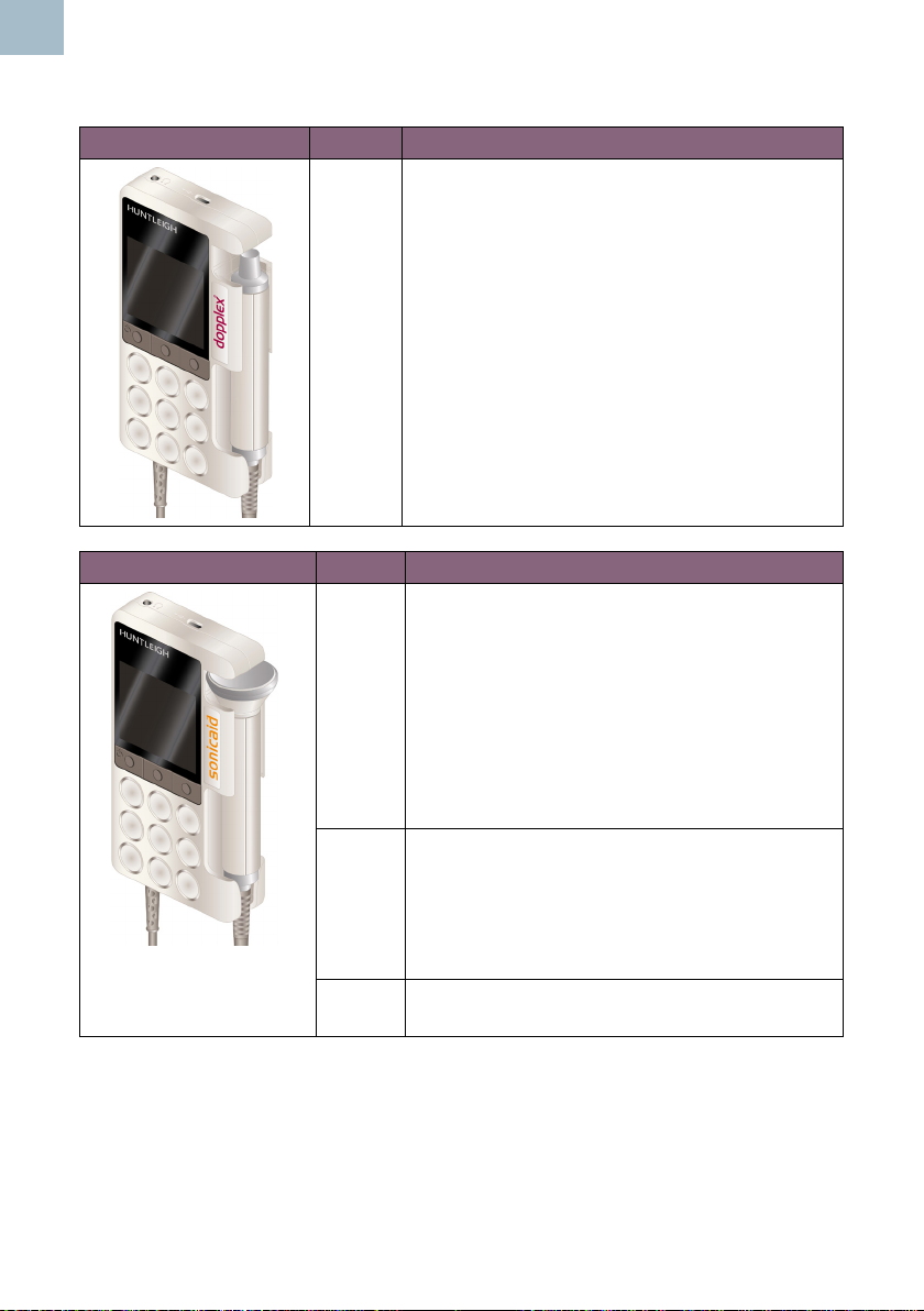
This manual applies to the following products:
VASCULAR DOPPLER MODEL FUNCTIONALITY
DMX Vascular - Full Visual and audio functionality if
a suitable vascular probe* is attached.
Obstetric - Full Visual and audio functionality
if a suitable obstetric probe* is attached. (Not
suitable for underwater monitoring).
PPG - PPG functionality if a PPG probe* is
attached.
OBSTETRIC DOPPLER MODEL FUNCTIONALITY
SRX Obstetric - Full Visual and audio functionality
if a suitable obstetric probe* is attached. (Not
suitable for under water monitoring).
Vascular - Audio functionality only if a suitable
vascular probe* is attached. Screen will display
date/time, probe frequency and battery status
only.
PPG - No functionality.
SR2 Obstetric - Full Visual and audio functionality.
2MHz hard wired waterproof probe suitable for
underwater monitoring.
No Vascular or PPG functionality as probe is
hard wired and cannot be changed.
SR3 Same as for SR2 model but with 3MHz hard
wired probe.
* Please see relevant sections for full details of functionality and probe /sensor options
and accessories.
8
Instructions For Use
Page 9
2.1 Intended Use & Indications
The DMX & SRX range of handheld Dopplers are intended for use by qualied
healthcare practitioners in primary, acute and community healthcare environments, for
the assessment of vascular blood ow and/or fetal heart rate, to assist in diagnosis.
2.2 Contraindications
The Doppler is not intended to be used on broken or fragile skin.
Do not use on the eye or scrotum.
The (Fetal) Doppler provides just one indicator of fetal condition. This
should be assessed as part of an holistic approach to obstetric care
together with other factors. A complete assessment must be made before
taking appropriate action. If there is any doubt concerning the accuracy
of any measurement, an alternative method should be used.
The (Vascular) Doppler is a screening tool to aid the healthcare
professional and should be used with clinical judgement before
interventional procedures are undertaken. If there is doubt as to
vascularity after using the unit, further investigations should be
undertaken immediately using alternative techniques.
EN
2.3 Battery Requirements
All models in the DMX and SRX range are compatible with the following battery types:
• Alkaline LR6 (non-rechargeable)
• NiMH HR6 (rechargeable)
Refer to Section 4.3.1 to set the battery type on the Doppler.
NiMH batteries can be charged by connecting the Doppler to the charger provided via
the USB port (refer to Section 3.1).
Do not attempt to recharge normal dry-cell batteries. They may leak,
causeareorevenexplode.
Do not mix non-rechargeable and rechargeable batteries.
Instructions For Use
9
Page 10

EN
2.4 Unpacking / Preliminary Checks
Contents
Item Item Item
1 x Digital Handheld Doppler Instructions for Use Batteries
Charger * USB lead * Ultrasound Gel
Quick Reference Guide Carry bag
* Depending on model
Delivery Inspection
Huntleigh Healthcare Ltd takes every precaution to ensure that goods reach you in
perfect condition. However, accidental damage can occur in transit and storage. For
this reason we recommend that a thorough visual inspection is made immediately the
unit is received. Should any damage be evident or any parts missing, ensure that
Huntleigh Healthcare Ltd is informed at once.
Storage
Refer to Section 5.8 and 8.8.
Note
Remove the batteries if the unit is not likely to be used for some time.
2.5 Service Life
This has been dened as the minimum time period during which the device is expected
to remain safe and suitable to meet its intended use, and all risk control measures
remain effective.
Huntleigh Healthcare Ltd’s commitment is that the expected service life for this Device
has been dened as 7 years.
10
Instructions For Use
Page 11
3. ProductIdentication
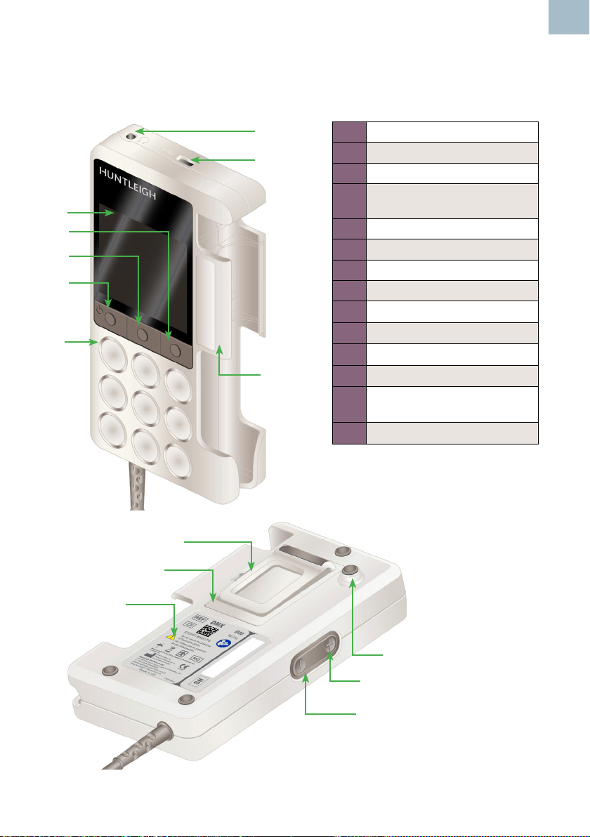
3.1 Product Controls
EN
1
2
3
6
5
4
7
8
1 Headphone Socket
2 USB Port
3 LCD Panel
Function Button 1 /
4
On/Off Button
5 Function Button 2
6 Function Button 3 / Setup
7 Loudspeaker
8 Probe Holder
9 Trolley Mount
10 Volume Up
11 Volume Down
12 Pocket Clip
Battery Compartment +
13
Micro SD Card Slot
14 Rear Panel Label
12
13
14
Instructions For Use
9
10
11
11
Page 12
EN
YYYY-MM
SN
REF
MD
DI
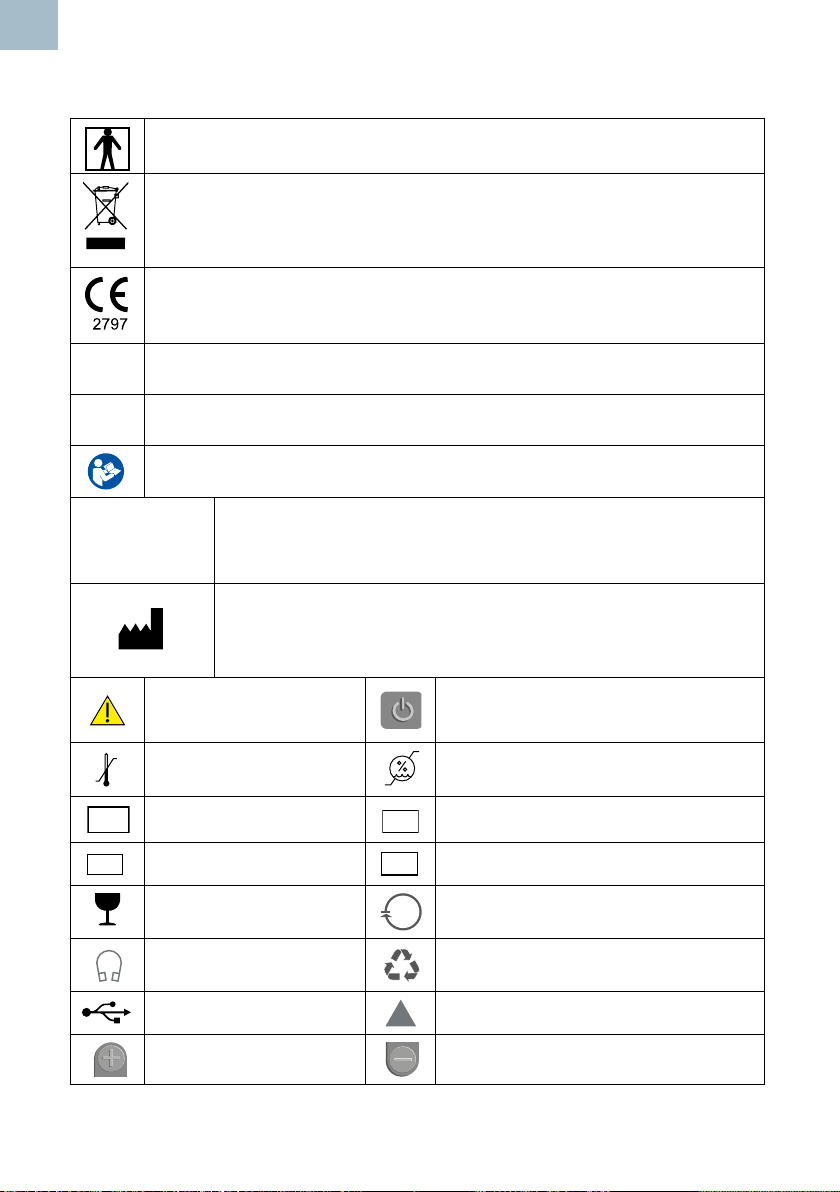
3.2 SymbolIdentication
Patient applied parts (ultrasound probes) are type BF according to the
denitions in IEC 60601-1:2005.
This symbol signies that this product, including its accessories and
consumables is subject to the WEEE (Waste Electrical and Electronic
Equipment) regulations and should be disposed of responsibly in
accordance with local procedures.
This symbol signies that this product complies with the essential
requirements of the Medical Device Directive (93/42/EEC) - Medical Device
Regulation (EU/2017/745)
Rx
Only
IP20
Federal law restricts this device to sale by, or on the order of a licensed
healthcare practitioner.
Protected against ingress of solid foreign objects >12.5mm diameter. Not
protected against ingress of water.
Attention, consult accompanying documents / Instructions for Use
Manufactured
By:
General warning Power On/Standby
50°C
-25°C
Temperature Limitations Limits of Relative Humidity
Serial Number
Medical Device
Fragile Contents can be recycled
Headphone Socket Cardboard packaging can be recycled.
USB Port Alignment mark
Volume Up Volume Down
Huntleigh Healthcare Ltd.
35 Portmanmoor Road, Cardiff, CF24 5HN, United Kingdom
T: +44 (0)29 20485885 [email protected]
www.huntleigh-diagnostics.com
Legal Manufacturer in association with the CE mark in Europe
ArjoHuntleigh AB
Hans Michelsensgatan 10 211 20 Malmö, Sweden
Model Number
Device Identier
12
Instructions For Use
Page 13
EN
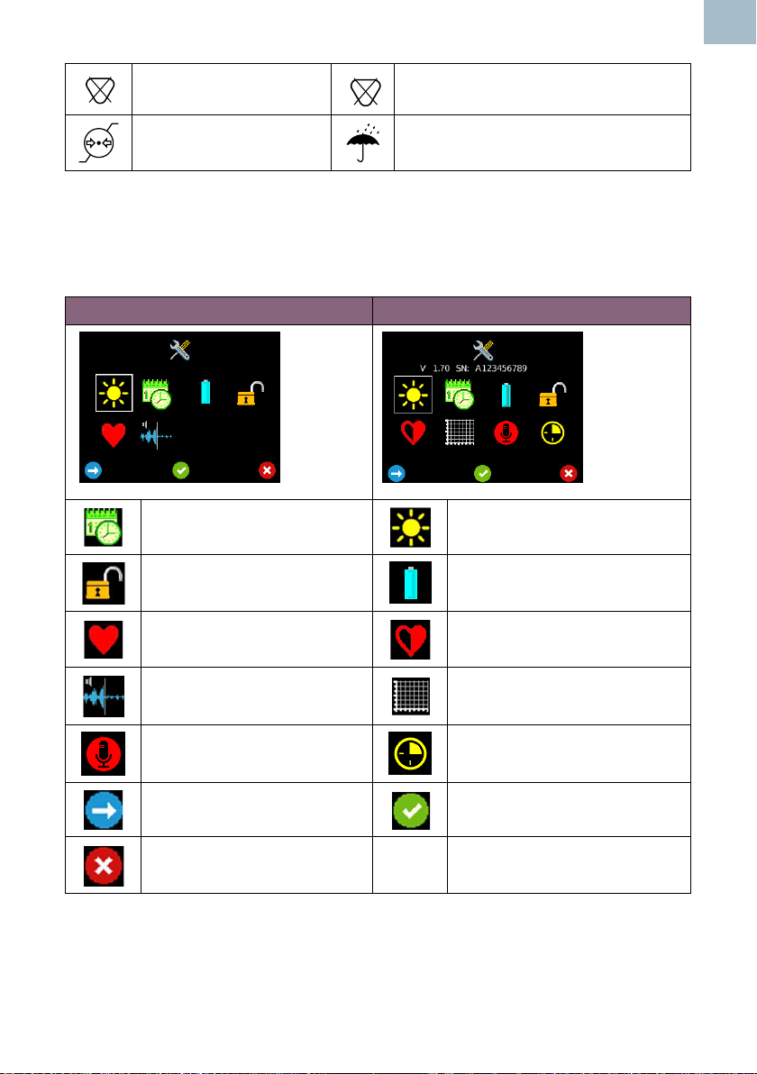
PVC FREE
PVC
Does not contain PVC
Limits of Atmospheric
Pressure
LATEX FREE
LATEX
Does not contain Latex
Keep Dry
3.3 Display
3.3.1 Setup Screen
Vascular Setup Screen Obstetric Setup Screen
Date and Time Setup Brightness
Lock screen Battery Selection
Heartrate Display Selection
(Vascular)
DDNR Hiss suppression
(Vascular)
Audio Recording (Obstetric) Timer (Obstetric)
Move Highlight Select
Exit Setup
Instructions For Use
FHR Averaging Mode
(Obstetric)
Trace Options (Obstetric)
13
Page 14
EN
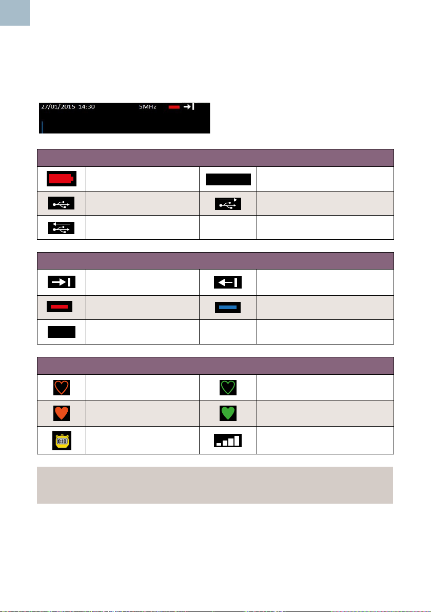
3.3.2 Status Bar
The Status Bar is visible at the top of the display on most screens, (not available in
Setup). The information displayed differs depending on the operating mode of the
Doppler.
- Status Bar (Vascular shown)
All Modes
Battery Level Low
27/01/2015 14.30
Date / Time
USB Connected USB Transmitting
USB Receiving
Vascular Mode
Forward Flow
(Flow towards probe)
Reverse Flow
(Flow away from probe)
Arterial Mode Venous Mode
5MHz
Probe Type
Obstetric Mode
Standard Mode - FHR
outside user set range
Smooth Mode - FHR
outside user set range
Standard Mode - FHR within
user set range
Smooth Mode - FHR within
user set range
Manual Mode Signal Strength
Note
Other Display icons will be explained throughout the manual in their respective
sections.
14
Instructions For Use
Page 15
4. Setup
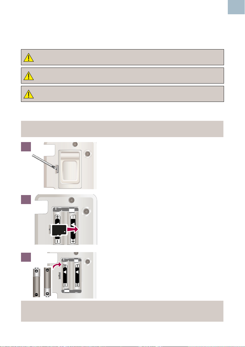
4.1 Battery Insertion / Replacement & Micro SD Card Insertion
Disconnect unit from any other equipment before removing the battery
cover.
IfyouarettingaMicroSDCardintotheDoppler,thismustbedone
BEFORE inserting the batteries.
Use Huntleigh recommended Micro SD cards only.
The Doppler is supplied with the batteries removed. Insert as shown below.
Note.
Refertosection8.4forthespecicationsofsuitablebatteries.
EN
1
Remove the battery cover :
Insert a suitable tool into recess to release the clip
and gently lever off the battery cover.
2
Insert the Micro SD Card. (If tting).
Ensure card clicks into place.
!
!
AA
AA
3
!
!
AA
AA
(To remove the Micro SD card, press
it in to release and pull gently to remove.)
Insert batteries in accordance with the diagram,
positive terminal rst, ensuring correct polarity.
Replace the battery cover.
Note
WerecommendtheDopplerischargedpriortorstuse.(ChargeONLYif
Doppleristtedwithrechargeablebatteries-SeeSection5.6).
Instructions For Use
15
Page 16
EN
4.2 Probe Connection
Note
ModelsSR2andSR3arettedwithhardwiredprobeswhichcannotbe
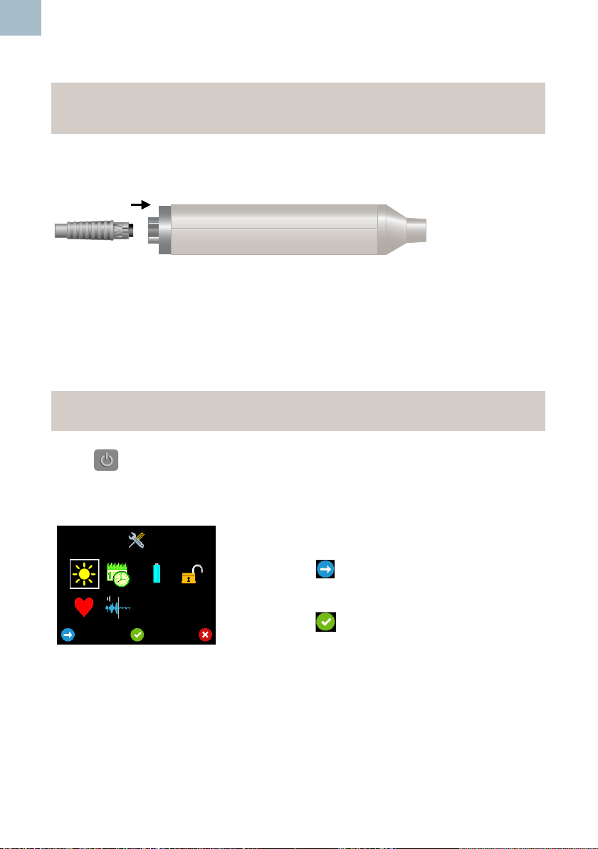
removed.
To connect the probe, align the arrow on the connector with the slot on the probe and
push rmly.
To disconnect the probe, pull the connector. DO NOT pull the cable.
4.3 Setup Screen
Note
A probe must be connected before the Setup screen can be accessed.
Press to turn the unit ON.
Press and hold Button 3 to access the Setup screen. (The screen shown is with a
vascular probe attached).
Use the 3 buttons below the screen to navigate and
select each function.
Press Button 1 to move the highlight to each option
.
Press Button 2 to accept your selection.
16
Instructions For Use
Page 17
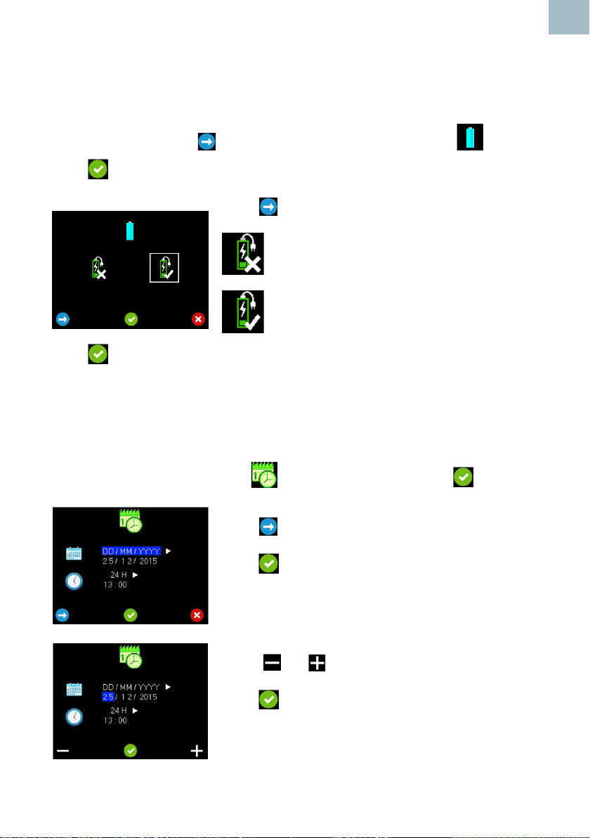
4.3.1 Battery Selection
The Doppler can operate from either alkaline or rechargeable NiMH batteries, but it is
important that the correct battery type is selected in the settings menu to correspond
with the battery type tted.
In the Setup menu, press to move the highlight to Battery Selection .
Press to accept your selection.
Press to move highlight between selections.
- Select for Alkaline batteries.
- Select for NiMH rechargeable
batteries.
Press to conrm and return to Setup screen.
4.3.2 Date and Time
EN
When the Doppler is switched on for the rst time, you will need to set the time and
date.
Highlight the Date and TIme option in the Setup menu and press .
Press to cycle through the Date format options.
Press to conrm and enter Date Edit Mode.
Press or to change the values
Press to Accept the value and move to next item .
When the nal item of the date has been accepted, Time
Format Selection mode is entered.
Instructions For Use
17
Page 18
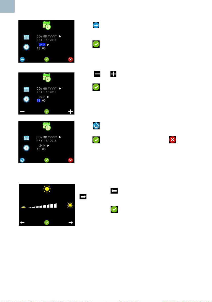
EN
Press to cycle through the Time format options. (i.e.
12H or 24H).
Press to conrm and enter Time Edit Mode.
Press or to change the values
Press to Accept the value and move to next item .
When the nal item of the Time has been entered, Date
and Time Conrmation mode is entered.
Press to return to the Date Format Selection screen.
Press accept and save the changes or to
discard the changes and return to the Setup screen.
4.3.3 Brightness
18
Press Button 1 to decrease Brightness and Button 3
to increase brightness.
Press Button 2 to conrm and return to the Setup
screen.
Instructions For Use
Page 19

4.3.4 Vascular, PPG and Obstetric Setup
Depending on whether a Vascular or Obstetric probe is attached, the Setup screen
allows you to access the Heartrate Display Selection Screen and DDNR Hiss
Suppression Screen (Vascular), and FHR Averaging Mode screen and Trace Options
screen (Obstetric). If a PPG probe is attached, this screen will allow access to PPG
monitoring functionality (Vascular). ATP and ABI kits are available to purchase as
optional extras.
These functions will be explained in the Operation section.
Note
The Setup screen can be accessed by pressing and holding Button 3 in the
main monitoring screens, i.e. Vascular Live Waveform screen, APPG Home
screen and Obstetric Numeric/Trace mode screens.
4.4 System Connection
WARNING: These requirements must be met when the Doppler is
connected to any other electrical equipment, such as a PC.
EN
1 Non-medical equipment must comply with the relevant IEC or ISO safety
standard. For Information Technology equipment, this standard is EN60950.
2 The congured system must comply with the requirements of
IEC 60601-1:2005; clause 16.
3 If non-medical equipment (e.g. the PC or printer) with enclosure leakage
currents greater than those allowed by IEC 60601-1 is to be used in the
patient environment (within 1.5m of the patient), the enclosure leakage
currents must be brought within the limits laid down by IEC 60601-1. This
may be achieved by using a medical grade isolating transformer. Suitable
types are available via Huntleigh sales agents.
4 Anyone who connects additional equipment to signal input or signal output
parts of the system is conguring a medical system, and is therefore
responsible for ensuring that the system complies with the
requirements of IEC 60601-1:2005; clause 16. If there is any doubt as to
whether your system complies, consult the technical service department or
your local Huntleigh representative.
Instructions For Use
19
Page 20
EN
5. Operation
Refer to diagram on Page 4 for Doppler Measuring sites and
Recommended Probes.
Note
All functions and screen displays are model dependent. Please see table in
‘Introduction’ section for details on the functionality available on each model.
Note
The Setup screen can be accessed by pressing and holding Button 3 in the
main monitoring screens, i.e. Vascular Live Waveform screen, APPG Home
screen and Obstetric Numeric/Trace mode screens
Coupling Gel
Use water based ultrasound gel ONLY.
5.1 Switching On
Press to turn the unit ON.
5.2. Vascular Mode
If a vascular probe is inserted into the SRX model Doppler, there will be
audio functionality only. The Doppler screen will display date/time, probe
frequency and battery status but no waveform or button details.
The Vascular Live Waveform screen is displayed automatically if a vascular probe is
detected when the device is powered on, or when a vascular probe is subsequently
inserted into the device.
Vascular Probes
Six probes are available for vascular examinations:
VP4XS 4MHz for deep lying vessels
VP5XS 5MHz for deep lying vessels and oedematous limbs
VP8XS 8MHz for peripheral vessels
VP10XS 10MHzforspecialistsupercialapplications.
EZ8XS 8MHZ “Widebeam” for peripheral vessels.
PA8XS Intraoperative Probe adaptor
20
Instructions For Use
Page 21
Patient Preparation
The patient must lie supine, be relaxed, remain still, and refrain from talking, coughing
etc.
Apply a liberal amount of gel on the site to be examined. Place the probe at 45° to
the skin surface over the vessel to be examined and point the probe tip towards the
heart. Adjust the position of the probe to obtain the loudest audio signal. High pitched
pulsatile sounds are emitted from arteries while veins emit a non-pulsatile sound similar
to a rushing wind.
For best results, keep the probe as still as possible once the optimum position has
been found. Adjust the audio volume as required.
5.2.1 Vascular Setup
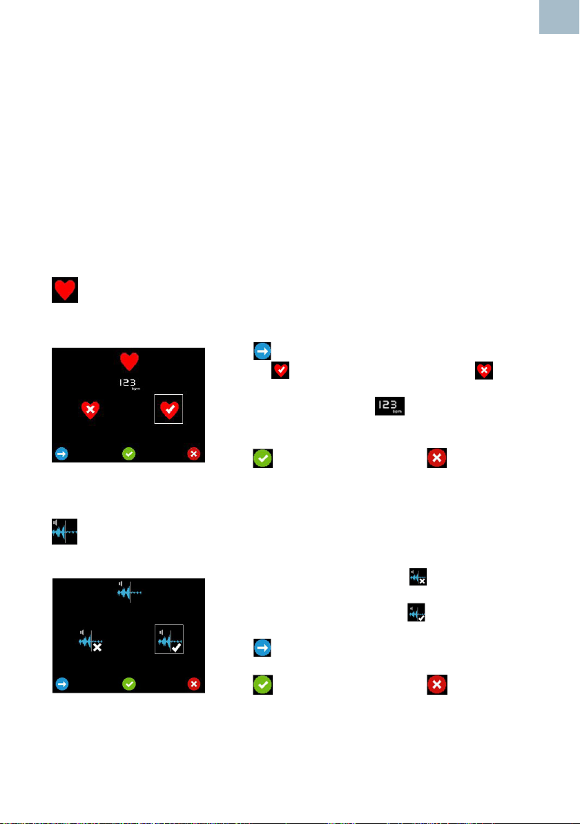
Heartrate Display Selection Screen
This selection determines if the heartrate gure is displayed when the trace is frozen.
Press to move the highlight between displaying the
heartrate and not displaying the heartrate .
The sample heartrate gure appears and
disappears accordingly.
EN
Press to accept your selection or to discard the
changes and return to Setup.
DDNR Hiss Suppression Selection Screen
This selection determines if the DDNR applies hiss suppression to the audio signal.
To disable hiss suppression select .
To enable hiss suppression select .
Press to move the highlight between selections.
Press to accept your selection or to discard the
changes and return to Setup.
Instructions For Use
21
Page 22
EN
5.2.2 Vascular Monitoring
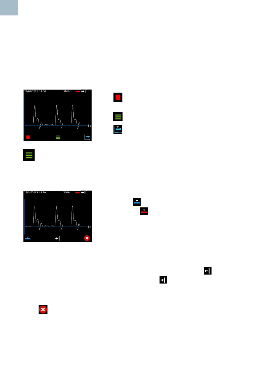
Vascular Live Waveform Screen
On the Vascular Live Waveform screen, the trace displays from left to right, then
begins overwriting again from the left hand axis. The time taken to traverse the screen
depends on the current time base and can be set to 3, 6 or 12 seconds. The currently
selected time base is displayed to the right of the chart level with the X axis (3 seconds
in the example shown).
Press to freeze the trace and display the Frozen
Options screen.
Press to display the Trace options.
Press To cycle through the Time base options (3s >
6s > 12s > 3s).
Vascular Waveform Options
The trace continues to update when the trace options are displayed. The soft key icons
will display the available options depending on the current settings. The status bar
displays the current settings.
If currently in Arterial Mode, button 1 will show Set
Venous Mode and if in Venous Mode, it will show
Set Arterial Mode .
Press button 1 to toggle between Venous and Arterial
modes and restore the live waveform soft keys.
Venous mode centres base line and defaults timebase to 12s.
Arterial mode offsets base line and defaults timebase to 3s.
If currently displaying Forward Flow, button 2 will show Set Reverse Flow and if
displaying Reverse Flow, it will show Set Forward Flow .
Press button 2 to toggle between Forward and Reverse Flow and restore the live
waveform soft keys
Press to restore the live waveform soft keys without making any changes to the
running state.
22
Instructions For Use
Page 23
Vascular Frozen Waveform Options
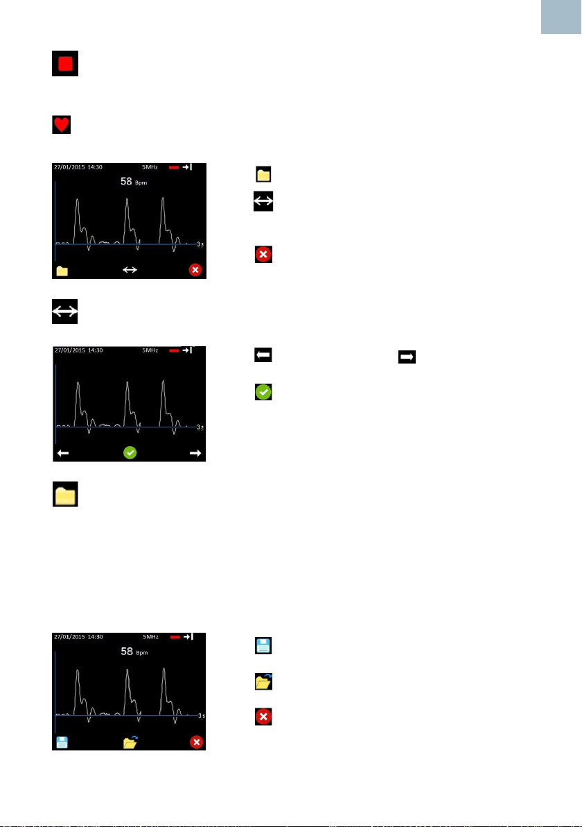
When the waveform is frozen, the heartrate is displayed. (If the option has been
selected in setup - See Heartrate Display Selection Screen in Vascular Setup section
). Once the trace is stopped the time base cannot be changed, so this must be
selected beforehand.
Press to display the File Options.
Press to show the scroll options. (This button will
only be displayed if more than a screen of data has been
captured).
Press to exit and return to Live Waveform screen.
Vascular Scroll Options
Press to scroll left / back or to scroll right /
forward through the trace.
Press to accept the displayed portion of the trace
and return to the Frozen Waveform Options screen.
EN
Heartrate is not shown while scrolling.
VascularFileOptions(IfMicroSDcardtted)
From this screen, the user can choose to save a waveform or open the folder
containing previously stored waveforms for review. If there is insufcient memory to
save a waveform, the save option is unavailable and the save icon is hidden. In this
case the user should go to the review les screen and delete one or more stored les
to free up memory.
The lename will be generated automatically and a popup temporarily displayed to
acknowledge that the le has been saved. Data is stored on the Micro SD card.
Press to save the visible portion of the waveform
to permanent storage.
Press to open the folder containing stored
waveforms for review.
Press to exit back to the Frozen Waveform Options
screen.
Instructions For Use
23
Page 24
EN
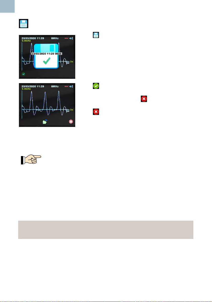
Save Trace
Press to save the recorded trace.
A popup will be displayed momentarily to conrm
successful save .
The popup will display the le identier which includes
Date, Time and a four digit index number.
Press to acknowledge lename and continue to the
following screen.
If data has been saved, press to exit to frozen
vascular waveform Screen.
Press again to return to the live vascular waveform
screen.
5.2.3 Measuring Doppler Pressures
Refer to diagram on Page 4 for Doppler Measuring sites and
Recommended Probes.
Pressure measurements rely on a bulb ination / valve deation system in combination
with a tube and cuff attachment as shown below.
Brachial Systolic Pressure
Rest the patient in supine position in a quiet warm room for at least 10 minutes.
Place the cuff on the upper arm approximately 1-2 cm above the antecubital fossa.
Connect the sphygmomanometer to the cuff.
Note
Select cuff size appropriate for the patient’s limb. Ensure that the index marker
on the cuff falls within the range marker.
24
Instructions For Use
Page 25

Apply a liberal amount of gel on the site of the
brachial artery.
Place the probe at 45° to the skin surface over the
vessel to be examined and keep the probe tip in
line with the vessel.
Adjust the position of the probe to obtain the
loudest audio.
For best results, keep the probe as still as possible
once the optimum position has been found.
Adjust the audio volume as required.
Inate the BP cuff by compressing the bulb of
the sphygmomanometer until the pulse sound
disappears and then further inate by 10 – 20
mmHg.
Gradually deate the cuff (2 mm/sec) and note the
pressure on the sphygmomanometer at which the
arterial sounds return.
Deate the cuff completely.
EN
Ankle Systolic Pressure
Place the appropriately sized cuff 1-3 cm above the lateral malleolus.
Connect the sphygmomanometer to the cuff.
Repeat the procedure described above, only this time monitoring the desired foot artery
(e.g. Posterior Tibial shown).
Instructions For Use
25
Page 26

EN
5.3 PPG Mode
This function is only available on the DMX model.
The PPG Home Screen is displayed automatically if an PPG module is detected when
the device is powered on, or when an PPG module is subsequently connected to the
device. (Available as an optional accessory).
APPG Probes
An arterial PPG probe is available for arm, ankle and toe systolic pressures and PPG
waveforms:
PPGA1 Photo Plethysmography Probe
Systolic pressure measurements rely on a a bulb ination / valve deation system in
combination with a tube and cuff attachment as shown overleaf.
The Photo plethysmography probe is attached to the arm, ankle or toe as appropriate,
and uses infra-red light to make a relative measurement to detect the return of
bloodow.
The cuff is wrapped around the patient’s extremity, and the pressure in the cuff is
recorded by a pressure sensor located inside the PPGA1 module. The pressure
transducer records the cuff pressure values as a function of time. These readings are
presented graphically on the display, allowing the user to make the determination of
which pressure reading is the actual systolic pressure.
Connect the cuff, sphyg, APPG adaptor and probe as shown:
26
Instructions For Use
Page 27
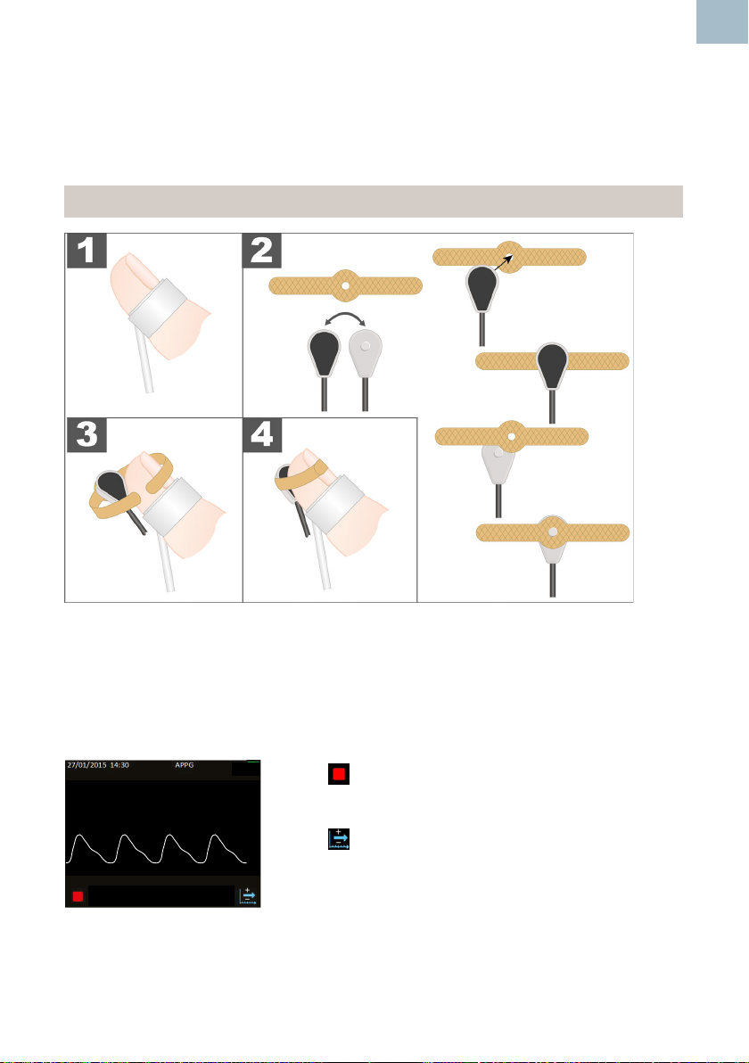
Patient Preparation
Patient must rest for 10 minutes in a warm room (> 24°C).
Patient must be supine with stockings and footware removed.
Temporarily cover feet to keep them warm until measurement is made.
Fit the sensor & toe cuff as shown.
Note: Select cuff size appropriate for the patient’s toe/digit.
EN
APPG Home Screen
The PPG trace runs in real time at the selected time base and is auto scaled to
optimise the display height. The time base can be set to 3, 6 or 12 seconds. The
currently selected time base is displayed to the right of the chart level with the X axis (3
seconds in the example shown).
Press to freeze the trace and display the APPG
0 mmHg
Trace Only screen.
Press to cycle through the time base options: 3s >
3s
6s > 12s > 3s.
Instructions For Use
27
Page 28
EN
APPG Trace Only Screen
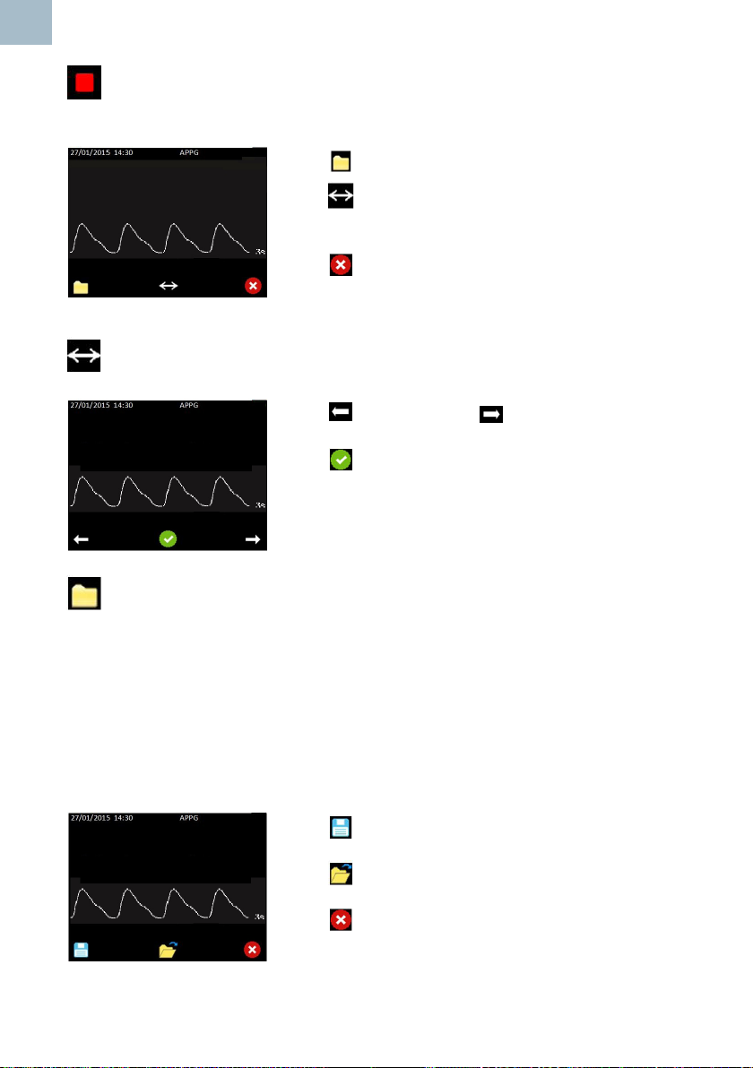
The required time base should be selected before freezing the trace.
Press to display the File Options.
Press to show the scroll options. (This button will
only be displayed if more than a screen of data has been
captured).
Press to exit the APPG Trace Only screen, return to
the APPG Home Screen and restart the trace.
APPG Scroll Options
Press to scroll back or to scroll forward through
the trace.
Press to accept the displayed portion of the trace
and return to the APPG Trace Only screen.
APPGFileOptions(IfMicroSDcardtted)
From this screen, the user can choose to save a waveform or open the folder
containing previously stored waveforms for review. If there is insufcient memory to
save a waveform, the save option is unavailable and the save icon is hidden. In this
case the user should go to the review les screen and delete one or more stored les
to free up memory.
When saving a waveform, only the portion of the waveform displayed on the screen
is actually saved. The user should scroll the desired portion of the waveform into
view before saving. The lename will be generated automatically and and a popup
temporarily displayed to acknowledge that the le has been saved.
Press to save the visible portion of the waveform to
permanent storage
Press to open the folder containing stored
waveforms for review.
Press to exit back to the APPG Trace Only screen.
Refer to APPG nal review and Save section for further
28
information.
Instructions For Use
Page 29
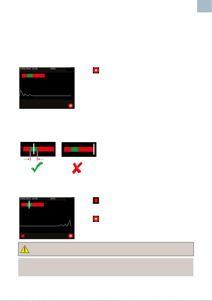
Measuring a Toe Systolic Pressure
This screen shows the PPG waveform and the instantaneous cuff pressure in real time.
Inate the cuff and stop at a target pressure approximately 30 mmHg above that at
which blood ow is totally occluded.
It is the responsibility of the user to note the pressure at which blood ow is totally
occluded and continue inating for a further 30mmHg.
EN
160 mmHg
Press to exit back to the APPG Home screen.
6s
The user will now aim to reduce the pressure by pressing the vent button on the
sphyg to achieve a constant rate of 2 – 4 mmHg per second. To assist the user,
the deation bar indicates the current calculated deation rate. If it is between 2
– 4 mmHg, the white line will be over the green band. The red bands either side
correspond to rates that are either too low or too high.
Cuff pressure is plotted in the Right Hand upper corner.
When the returning pulses are detected, the screen is frozen, and the Pressure Adjust
screen is entered.
160 mmHg
Press to Freeze trace and display Pressure Adjust
screen.
Press to exit back to the Pressure Inate screen.
6s
Alwaysdeatethecuffpressuretozeroafterthetracestops.
Note
If the cuff pressure remains above 10mmHg the displayed cuff pressure will
turnorangeandash.
Instructions For Use
29
Page 30
EN
Note
If the cuff pressure exceeds the nominal range shown in Section 8, it will be
displayed as ‘- - - ‘ mmHg.
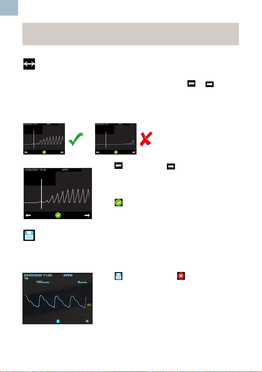
APPG Systolic Pressure Adjust Screen
The rst pulse detected will be aligned with the vertical line. If this is not the case, the
user can manually adjust the detected systolic pressure using the or buttons
.This may be useful if the user believes the rst detected pulse to be random noise.
The trace can be moved in either left or right directions, with the vertical line remaining
static. The pressure shown above the vertical line is updated accordingly.
Ensure that the rst pulse is aligned with the vertical line.
125 mmHg
0 mmHg
141 mmHg
6s
0 mmHg
6s
Press to scroll back or to scroll forward through
the trace.
125 mmHg
0 mmHg
Indicated pressure reduces or increases.
6s
Press to accept the selected systolic pressure.
APPG Final Review and Save Screen
The detected or adjusted systolic pressure is displayed at the top left hand corner
of the display. The APPG waveform saved when the Cuff was rst inated beyond
30mmHg in the APPG Home screen is displayed.
Press to save or press the icon to exit without
saving.
30
Instructions For Use
Page 31
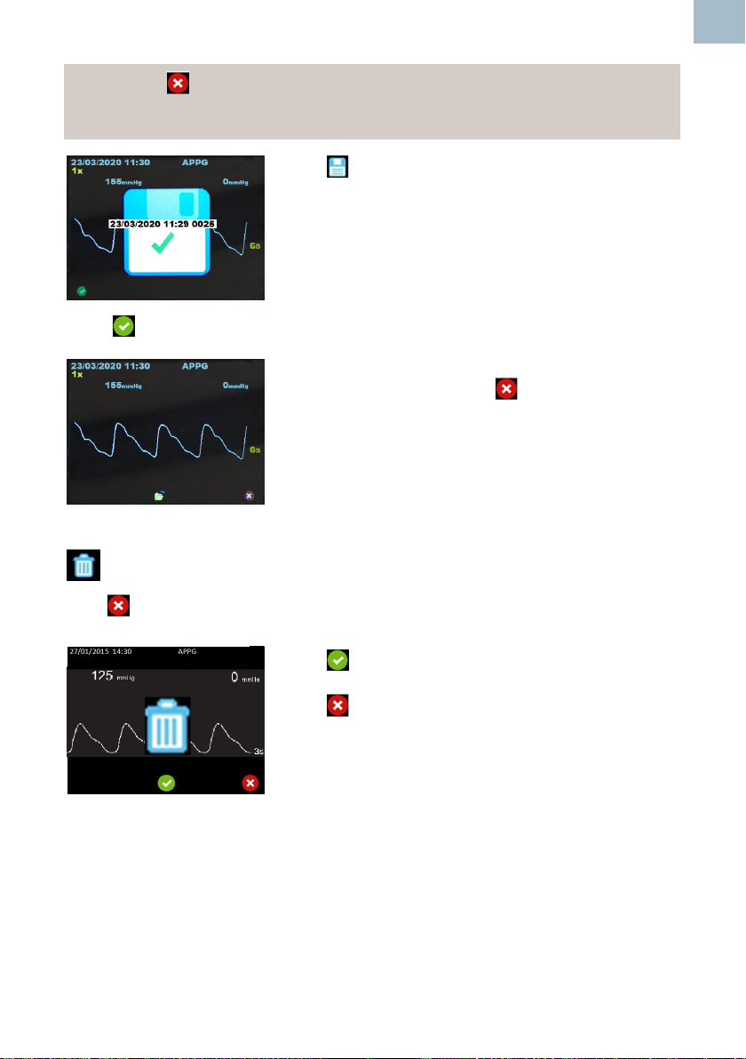
Note - If the Icon is pressed the ‘Data will be lost’ screen is displayed
prompting the user to reconsider exiting the Final Review and Save Screen
without saving the record.
Press to save the recorded trace.
A popup will be displayed momentarily to conrm
successful save .
The popup will display the le identier which includes
Date, Time and a four digit index number.
Press to acknowledge lename and continue to the following screen.
If data has been saved, press to exit to the APPG
home screen.
EN
APPG Data Will Be Lost Screen
If the icon is pressed in the Final Review and Save Screen the user will be
prompted to reconsider exiting without saving the record.
Press to exit to APPG Home screen without saving.
Press to return to Final Review and Save screen.
Instructions For Use
31
Page 32
EN
5.4 Obstetric Mode
The Obstetric FHR Numeric screen is displayed automatically if an obstetric probe is
detected when the device is powered on, or when an obstetric probe is subsequently
inserted into the device.
Obstetric Probes
Two probes are available for obstetric examinations:
OP2XS 2MHz ±1% OP3XS 3MHz ±1%
Doppler Signal Strength
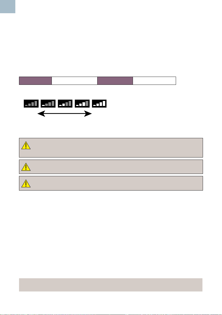
The strength of the Doppler signal is
displayed in the status bar at the top of the
No
Signal
Strong
Signal
Underwater Monitoring - SR2 and SR3 models only!
ModelsSR2andSR3arettedwithhardwiredwaterproofprobes
suitable for underwater monitoring. Other probes are not waterproof and
must not be used in water.
display.
For underwater use where contamination or cross-infection may occur,
refer to Section 6 for Cleaning Instructions.
The main unit is not waterproof and must not be immersed.
Patient Preparation
Make the patient comfortable in a semi-recumbent or sitting position.
Apply a liberal amount of gel* to the abdomen. Where practical, palpate rst to
determine fetal position - best probe position is over the fetal left scapula. Place the
faceplate of the probe at against the abdomen above the symphysis pubis. Adjust
the probe to obtain an optimum audio signal ideally by angling the probe around while
maintaining rm pressure. Avoid sliding it over the skin.
In early pregnancy a full bladder may improve sound detection. In later pregnancy the
best signals are generally located higher on the abdomen. The fetal heart sounds like a
galloping horse at approximately twice the maternal rate.
Best heart rate performance is from the fetal heart itself, characterised by ‘slapping’
valve sounds, rather that umbilical artery or placental sounds.
*Note: For SR2/SR3 Models : Gel is not required when probe is used
underwater.
32
Instructions For Use
Page 33
5.4.1 Obstetric Setup
FHR Averaging Mode Selection Screen
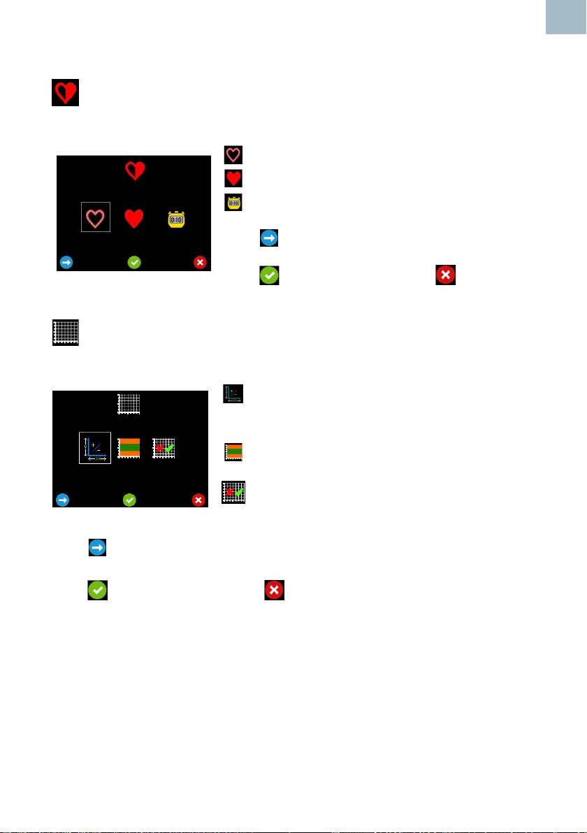
This selection determines the method used to calculate the Fetal Heartrate.
- Selects Standard Averaging Mode over 4 beats.
- Selects Smooth Averaging Mode over 8 beats.
- Selects Manual mode where the user times 10
beats
Press to move the highlight between selections.
Press to accept your selection or to discard the
changes and return to Setup.
Trace Options Screen
This screen provides a submenu of option screens to dene the properties of the trace
display.
- Go to the Chart Speed / Y Axis Scale Selection
screen.
EN
- Go To the Threshold Limit Selection screen.
- Go to the FHR Trace Mode Enable / Disable
screen.
Press to move the highlight between selections.
Press to accept your selection or to discard the changes and return to Setup.
Instructions For Use
33
Page 34
EN
Chart Speed / Y Axis Scale Selection Screen
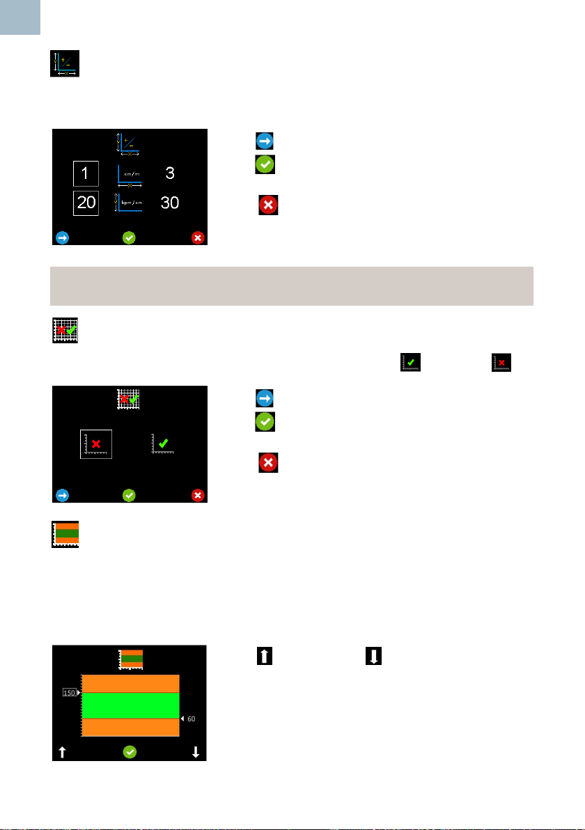
This screen allows the Obstetric trace chart speed and Obstetric trace chart Y Axis
scale to be set.*
Press to move the highlight between selections.
Press to accept your selection and return to the
Trace Options screen.
Press to return to the Trace Options screen without
saving the changes.
*Note
Each grid division on the chart represents one centimetre equivalent.
FHR Trace Mode Enable / Disable Screen
This screen allows the FHR Trace Mode Screen to be enabled or disabled .
Press to move the highlight between selections.
Press to accept your selection and return to the
Trace Options screen.
Press to return to the Trace Options screen without
saving the changes.
Threshold Indication Limits Selection Screen
On entering this screen, the current upper limit (left) and lower limit (right) are displayed
(upper limit is shown selected). The area of the chart in green represents heartrate
levels within the user set range. The areas in orange represent rates outside the user
set levels. When the heart rate is outside these user set levels, the heart symbol
changes from green to amber.
Press to increase or to decrease the selected
level by 5.
As the levels change, the new values are displayed and
the areas of the graph change accordingly.
34
Instructions For Use
Page 35
Press to move the selection from upper level to the lower level. Adjust the selected
level with and .
Press . Conrmation softkey functions will be displayed giving the options to Redo
, Accept or cancel the changes.
Accept or Cancel will return to Trace Options screen.
Fetal Heart Audio Record Screen- Refer to Section 12.
Timer Function Screen - Refer to Section 12.
5.4.2 Obstetric Monitoring
Obstetric FHR Numeric Mode Screen
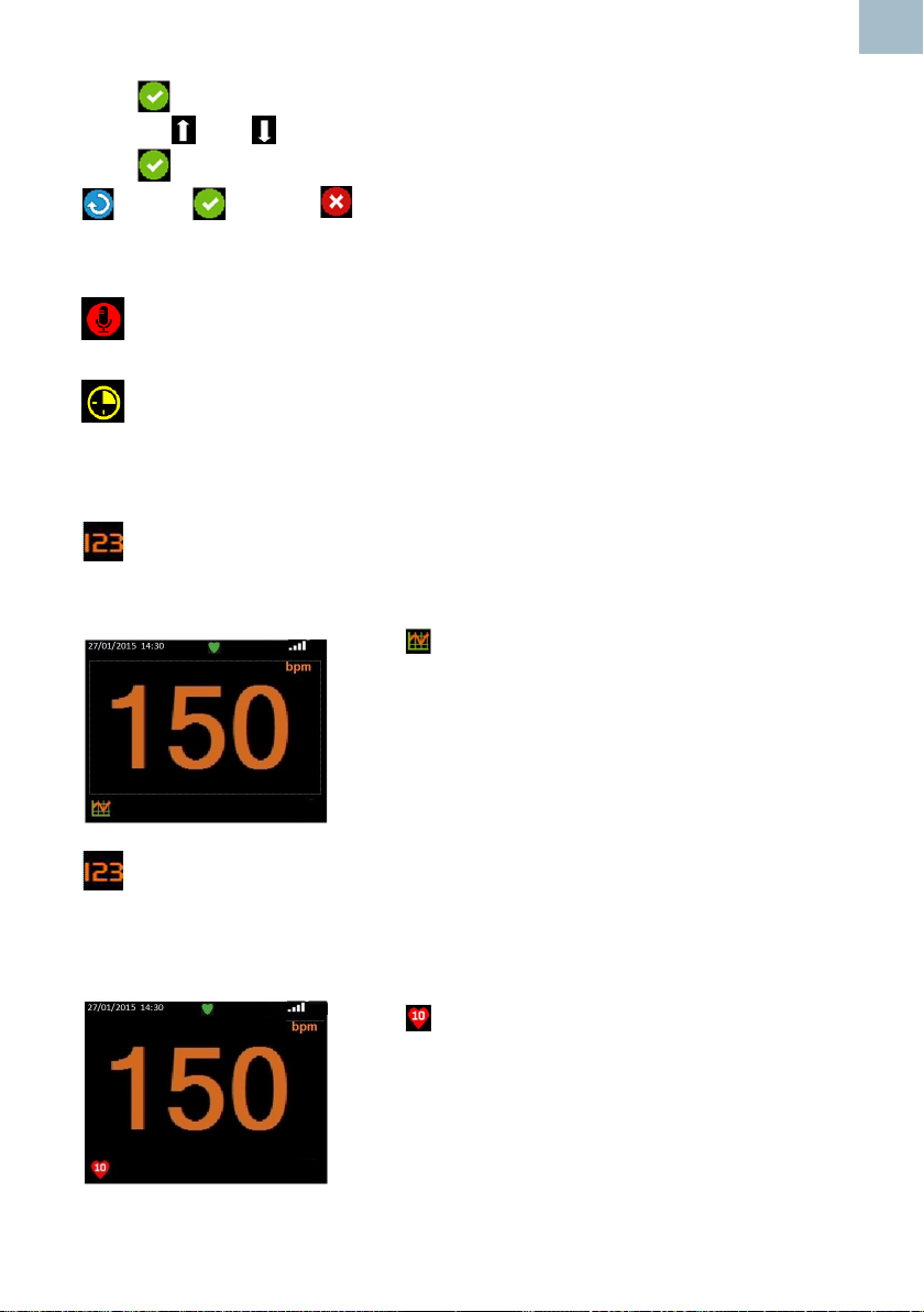
In this Mode, the FHR is displayed (in beats per minute) in large digits and is
continually updated. When the rate cannot be determined, 3 x dashes are displayed.
Press to switch to FHR Trace Display.
EN
Obstetric FHR Numeric Mode Screen (Manual)
In manual mode (selected from setup), the display initially shows three dashes in place
of the digits. This mode allows a 10 beat average heart rate to be measured, where the
user can hear a weak or noisy heart beat but the Doppler is unable to calculate FHR.
Press (Button 1), count 10 beats then press again.
The Doppler will calculate and display the FHR based on
the time taken. The FHR will remain on screen until the
operation is repeated or the mode is changed.
Instructions For Use
35
Page 36
EN
Obstetric FHR Trace Mode Screen *
Trace display mode is for indication only and is not a replacement for
conventional fetal monitoring. If any concern arises from viewing this trace,
alternative means (e.g. full CTG) must be used to determine fetal condition.
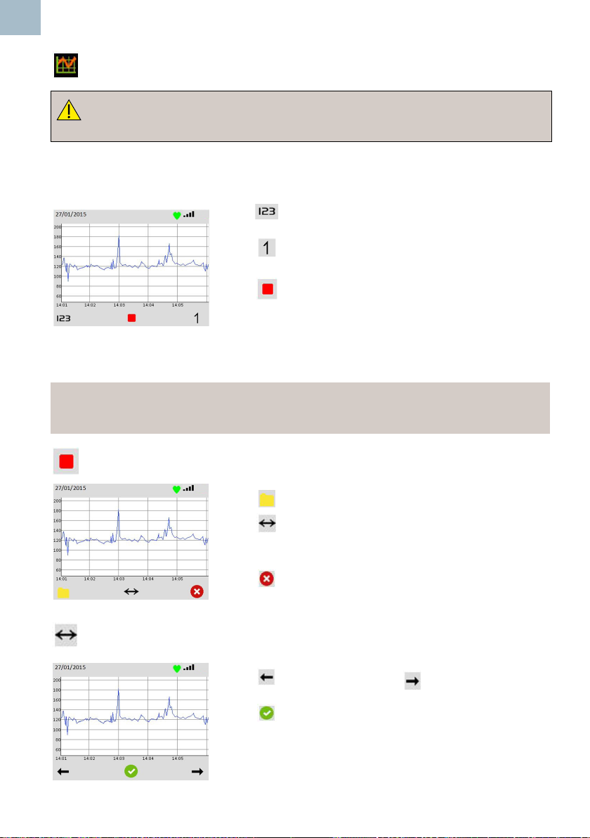
This screen displays the FHR as a trace on a graph. The horizontal and vertical scales
are determined in setup**. The trace displays from left to right until it lls the screen then
scrolls to the left as each new data point is added.
Press to switch to numeric display mode.
Press to register fetal movement and place a marker
on the graph at the corresponding position.
Press to stop the trace and display the FHR frozen
trace option.
** Trace scaling is equivalent to 1 or 3 cm/min and 20 or 30 beats per cm, scaled down
to screen size, maintaining the same aspect ratio to avoid distortion of the trace for easy
visual interpretation.
*Note
These options are only available if the FHR Trace Mode screen has been enabled
(see Section 5.4.1 - FHR Trace Mode Enable / Disable Screen).
36
Obstetric Frozen Trace Options *
Press to display the File Options.
Press to show the scroll options. (This button will only
be displayed if more than a screen of data has been
captured).
Press to display the Resume or Restart trace options.
Obstetric Scroll Options *
Press to scroll left / back or to scroll right /
forward through the trace.
Press to select the displayed portion of the trace and
return to the Frozen Trace Options screen.
Instructions For Use
Page 37
Obstetric File Options *
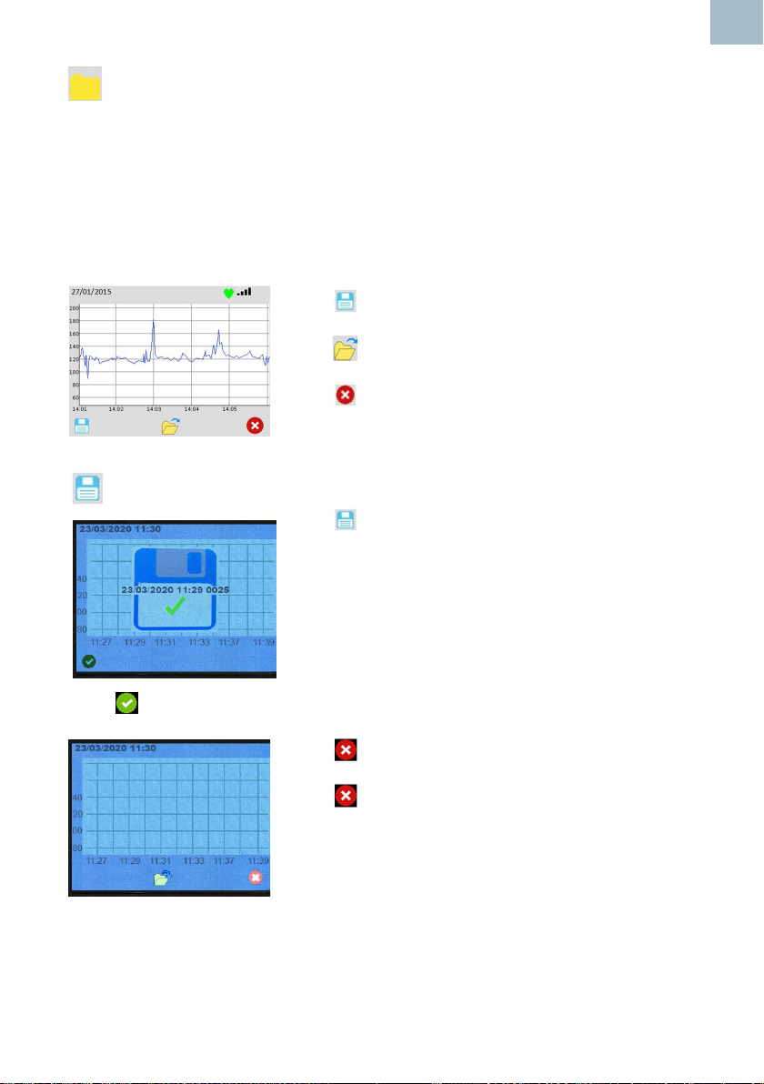
From this screen, the user can choose to save a trace or open the folder containing
previously stored traces for review. If there is insufcient memory to save a trace, the
save option is unavailable and the save icon is hidden. In this case the user should
go to the review les screen and delete one or more stored les to free up memory.
Memory capacity can be increased as required by installing an appropriate Micro SD
card.
The lename will be generated automatically and and a popup temporarily displayed to
acknowledge that the le has been saved.
Press to save the visible portion of the waveform to
permanent storage.
Press to open the folder containing stored
waveforms for review.
Press to exit back to the Frozen Trace Options
screen.
Save Trace
Press to save the recorded trace.
EN
A popup will be displayed momentarily to conrm
successful save .
The popup will display the le identier which includes
Date, Time and a four digit index number.
Press to acknowledge lename and continue to the following screen.
Press to return to the frozen FHR trace screen
Press again to return to the live FHR trace screen.
Instructions For Use
37
Page 38

EN
Obstetric FHR Trace Resume or Restart Options *
While the FHR trace is stopped / frozen, no further data is recorded. On exiting the
frozen state, the user can resume the current recorded trace or start a new trace.
Press to resume the current trace.
There will be a gap in the trace for the time period
corresponding to the frozen state.
Press to discard the current trace data and start a
new trace.
Note that discarding the current trace does not delete
any saved data les.
5.5 StoredleAccess
SavedFileConrmationPopup
Whenever a le is saved, a popup is overlaid.
File
Saving
Once the le has saved press to acknowledge the
lename and clear the popup.
File
Saved
File Save
Failed
Stored File Review Screen
A list of stored les is displayed with the most recent le at the top. A bar to the right
displays the amount of memory in use.
Press or to scroll through the le list.
Press to select the required le.
Press to view the selected waveform.
Press to delete selected waveform.
Press to conrm delete or to cancel and return
to File options.
38
Instructions For Use
Page 39

Press or to scroll through the pages of les.
Press to return to Live Trace screen.
Highlight and press to return to Live Trace screen.
Highlight and press to enter the Demo Files screen.
Demo Files
Demo les have been pre-programmed onto the SD Card.
EN
Vascular Demo Files Obstetric Demo Files
Press and to scroll through the le list and to select the required le.
Highlight and press to return to File Review screen.
Note
WhenanyDemoleisdisplayed,theautoswitchofftimeoutsaredisabled.
Instructions For Use
39
Page 40
EN
5.6 Battery Charging
Onlyrechargeablebatteriescanberecharged.Conrmbatterytype
before connecting to charger. (See Section 4.3.1).
Only use charger and lead supplied by Huntleigh. (See Section 8.4).
Do not use the Doppler on patients when connected to the charger.
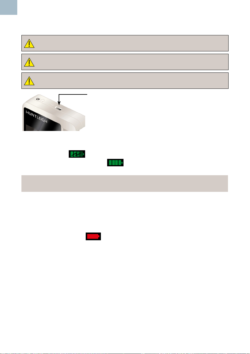
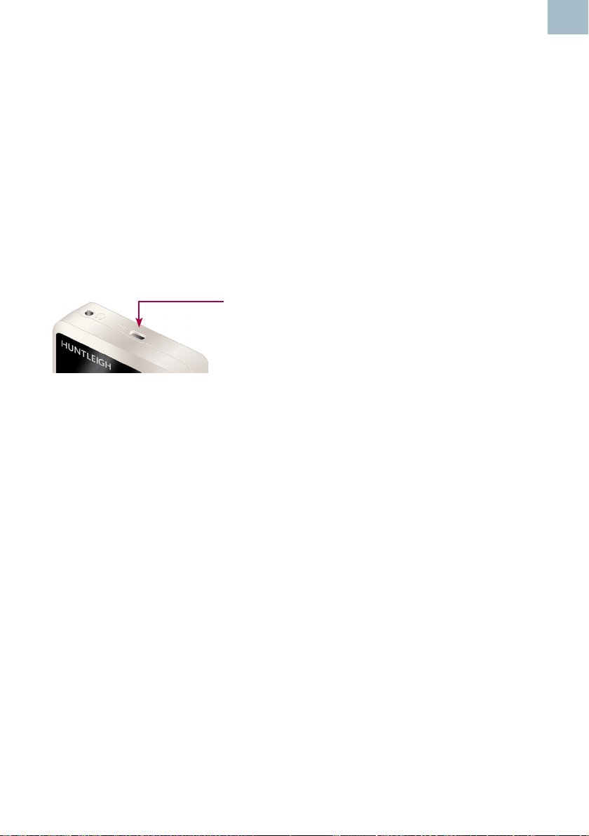
Insert the supplied charger lead into the USB socket at the
top of the Doppler.
Connect to mains supply and switch on mains power.
Charging will take approximately 5 - 6 hours, depending
on battery status.
During charging, a symbol will be displayed on the screen. Once fully
charged, the symbol will change to .
Note
The Doppler must be switched off for battery charging.
5.7 Battery Status
Approximately 500 x 1 minute examinations can be performed with fully charged
batteries, depending on use.
If the battery level is low, a symbol will appear on the Status bar.
When the battery is fully depleted, the Doppler will switch itself off.
5.8 Battery Care
If the Doppler is not to be used for some time, the following guidance should be
followed:
Non-rechargeable Batteries (Alkaline)
Remove the batteries from the unit. If the batteries are not removed, there is a risk of
battery leakage causing product damage.
40
Instructions For Use
Page 41
Rechargeable Batteries (NiMH)
Fully charge the batteries following the instructions in Section 5.6, then remove the
batteries from the unit. Store the batteries in a dry location within a temperature range
of 10°C to 30°C for up to six months.
For longer storage periods, the batteries should be re-tted to the Doppler, fully
charged and removed every six months.
If the batteries are not periodically re-charged, they can be irreversibly damaged.
5.9 Data transfer to an external device
The stored waveform/trace and data can be transferred to an external PC via a USB
connection.
Insert the supplied USB lead into the USB
socket at the top of the Doppler and connect to
the computer.
EN
5.10 After Use
1. Press and hold the On/Off button. If you forget to switch the unit off,
it will automatically switch off after 1 minute obstetric or 3 minutes
vascular.
2. Refer to the cleaning section before storing or using the unit on
another patient.
3. Store unit together with probe and accessories in the soft carry case
provided.
Instructions For Use
41
Page 42
EN
6. Care and Cleaning
6.1 General Care
All Huntleigh products have been designed to withstand normal clinical use, however
they can contain delicate components, for example the probe tip, which should be
handled and treated with care.
Periodically, and whenever the integrity of the system is in doubt, carry out a check of
all functions as described in the relevant section of the IFU. If there are any defects to
the housing contact Huntleigh or your distributor for repair or to order a replacement.
Please ensure that you check with your facility’s local infection control
policy and medical equipment cleaning procedures.
Observewarningsandguidanceoncleaninguidlabellingregardinguse
and personal protective equipment (PPE).
Do not use abrasive cloths or cleaners.
Do not use automatic washers or autoclaves.
42
Do not use Phenolic detergent based disinfectants, solutions containing
cationic surfactants, ammonia based compounds or perfumes and
antiseptic solutions.
If detergent or disinfectant wipes are used ensure that excess solution is
squeezed from the wipe prior to use.
Always switch off the Doppler and disconnect from the AC supply before
cleaning and disinfecting.
Donotallowanyuidtoentertheproductsanddonotimmerseinany
solution.
Always wipe off disinfectant using a cloth dampened with clean water.
Instructions For Use
Page 43
6.2 General Cleaning and Disinfecting
Always keep the external surfaces clean and free of dirt and uids using a clean dry
cloth.
1. Wipe any uids from the surface of the product using a clean dry cloth.
2. Wipe with a cloth dampened in 70% Isopropyl Alcohol.
3. Completely dry with a clean, dry cloth.
4. If the product has been contaminated use the methods described for
patient applied parts..
6.3 Cleaning and Disinfecting Patient Applied Parts
Probes *
Clean the probes before examining a patient using low risk cleaning method below.
Following patient examination, clean and/or disinfect the probes by the appropriate
method based upon the level of cross contamination risk, as dened below:
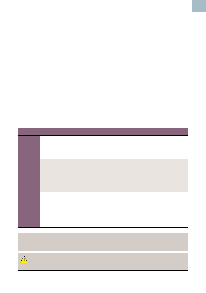
Risk Denitions Procedure
Low Normal use or low risk
situations include patients
having intact skin and no
known infection.
Medium The patient has a known
infection, skin is not intact, the
part is heavily soiled.
High This procedure should only
be used when the part has
been contaminated by blood.
1. Remove soiling, wipe with a mild
neutral detergent and then wipe
with a cloth dampened in water.
2. Completely dry with a clean cloth.
1. Follow low risk procedure then
wipe with a cloth dampened in
Sodium Hypochlorite (1,000ppm).
2. After two minutes wipe with a cloth
dampened in water and then dry
with a clean cloth.
1. Follow low risk procedure then
wipe with a cloth dampened in
Sodium Hypochlorite (10,000ppm).
2. After two minutes wipe with a cloth
dampened in water and then dry
with a clean cloth.
EN
*Note
Does not apply to IOP8 Intraoperative Probe. Refer to Intraoperative Probe IFU
for details on cleaning/sterilisation processes.
Warning: Repeated and unnecessary use of concentrated solutions
will result in damage to the product. Do not allow Sodium Hypochlorite
solutions to come into contact with metal parts.
Instructions For Use
43
Page 44
EN
The use of disinfectant materials other than those listed is the responsibility of the user
for their efcacy and compatibility with the device.
Cuffs
Clean the cuffs before examining a patient using the low risk cleaning method below.
Following patient examination, clean and/or disinfect the cuffs by the appropriate
method based upon the level of cross contamination risk, as dened below:
Before tting the cuffs to the patient, evaluate the cross-contamination risk according to
the denitions in the tables below:
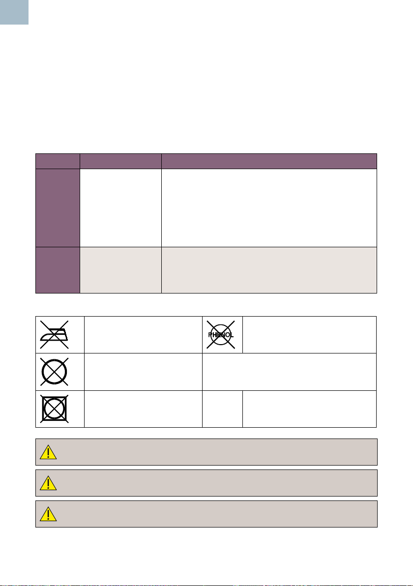
Risk Denitions Procedure
Low Normal use or
low risk situations
including patients
with intact skin
and no known
infection.
Medium/
High
The patient has a
known infection, or
skin is not intact.
1. Clean with soft cloth and a mild, neutral
detergent @ 40°C (104°F)
2. Disinfect using a 70% isopropyl alcohol
wipe or chlorine releasing agent @
1000ppm available chlorine
3. Wipe with a cloth dampened in clean water.
4. Completely dry with a clean lint-free cloth
Because of the nature of the cuff materials, effective
cleaning and disinfection in high risk situations is not
practical. Therefore, we recommend to dispose of
according to local procedures
44
Do not iron Do not use phenol or phenol-
derivative disinfectant.
Do not dry clean Do not machine wash. Do not immerse
tubeset in water.
Do not tumble dry
CAUTION
Donotallowanyuidtoenterthecufftubing.
CAUTION: Do not use alternative cleaning agents or methods as
permanent damage is likely.
CAUTION
Inspect cuffs after cleaning and prior to use.
Instructions For Use
Page 45

Cuff Inspection:
Cuffs should be regularly inspected. Examine the outer cuff surfaces for material
damage, splitting, fraying etc. Make sure that labelling is clearly legible. Check the cuff
tubing and connections for damage, splits etc. If in any doubt as to the condition, the
cuff(s) should be replaced. In any case, cuffs should be replaced every two years.
CAUTION
After using chemicals ALWAYS rinse off / remove the chemical with
absorbent material, dampened in clean water and dry with a clean cloth.
6.4 Maintenance and Repair
There are no user serviceable parts inside the Doppler unit or probes.
Inspection is recommended each time the product is used, paying particular attention
to the tip of the probes, checking for cracks etc., and to the cable and connector. Any
crackling or intermittent behaviour should be investigated.
This product does not require periodic maintenance.
Suitable test equipment and a full range of spare parts are also available. Please refer
to service manual for further information and part numbers.
EN
A full technical description is provided in the Service Manual 772490.
Instructions For Use
45
Page 46

EN
7. Troubleshooting
This section gives some of the more common problems encountered during use
together with possible causes. If the problem cannot be located after consulting the
table in this section, the Doppler should be switched off and a qualied technician
should be consulted.
Before attempting trouble-shooting, verify that the batteries are charged.
SYMPTOM POSSIBLE CAUSE / REMEDY
Doppler will not turn on. Replace / re-charge batteries.
Audio Only Doppler model does not support visual functionality
No Audio signal Incorrect volume setting
Poor Signal Probe / sensor incorrectly positioned
Insufcient Gel
No Signal Damaged probe / sensor
Incorrect probe / sensor
Screen displays:
Damaged probe / sensor
No Probe
Screen displays: Incompatible probe / sensor
Incorrect Probe / sensor
Screen displays: Incorrect battery tted
46
Instructions For Use
Page 47
8. Specications
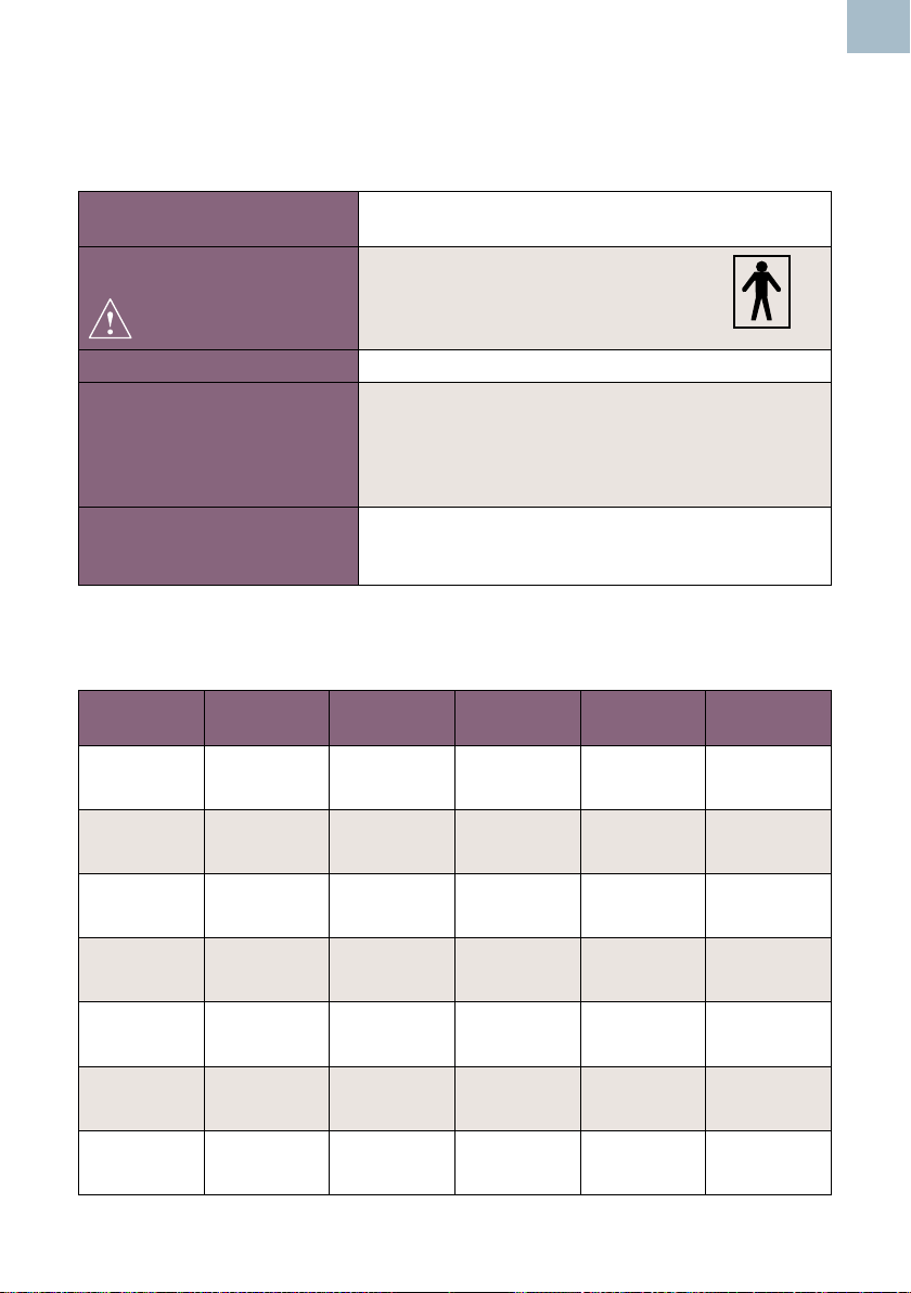
8.1 EquipmentClassication
EN
Type of protection against
electric shock.
Degree of protection
against electric shock
Mode of operation. Continuous
Degree of protection
against harmful ingress of
particles and/or water.
Degree of safety of
application in the presence
ofaammableanaesthetic
Internally powered equipment
Type BF - equipment with an applied part
Main Unit: IP20
Doppler Probes: IPX1
PPGA1 module : IPX0
SR2/SR3 probes : IPX7
Protective Pouch : IPX2
Equipment not suitable for use in the presence of a
FLAMMABLE ANAESTHETIC MIXTURE WITH AIR,
OXYGEN OR NITROUS OXIDE
8.2 DMX / SRX Ultrasound Transducers’ Global Maximum
Values
Transducer
Model
OP2XS 20 Soft Tissue
OP3XS 13 Soft Tissue
VP4XS 30 Soft Tissue
VP5XS 20 Soft Tissue
VP8XS 10 Soft Tissue
EZ8XS 60 Soft Tissue
VP10XS 20 Soft Tissue
Ispta .3
(mW/cm2)
TI Type TI Value MI Ipa .3@
MImax
Bone
Bone
Bone
Bone
Bone
Bone
Bone
0.11
0.29
0.09
0.19
0.062
0.21
0.08
0.16
0.039
0.1
0.17
0.37
0.029
0.08
0.017 N/A
0.016 N/A
0.014 N/A
0.0103 N/A
0.005 N/A
0.015 N/A
0.0069 N/A
Instructions For Use
47
Page 48

EN
8.3 SRX FHR Performance*
Standard Mode Range - 60-210bpm Resolution - 1bpm
Averaging - 4 beats Accuracy - ±3bpm
Smoothed Mode Range - 60-210bpm Resolution - 1bpm
Averaging - 8 beats Accuracy - ±3bpm
Manual Mode Range - 60-210bpm Resolution - 1bpm
Averaging - 10 beats Accuracy - ±3bpm
8.4 DMX Vascular Doppler Performance
Doppler Heart Rate
Range 40 – 200 bpm
Accuracy* ± 3 bpm
*Heart rate indications may be unreliable if the signal is weak or irregular
Doppler bandwidth (+0; -3 dB)
VP4XS, VP5XS 170 to 4,600 Hz
VP8XS, EZ8XS 270 to 6,000 Hz
VP10XS 270 to 8,000 Hz
IOP8 110 to 7,400 Hz
*(excluding user error)
Doppler Shift Maximum Frequency Display Error**
Typically < 5%; maximum 10%
8.5 ABI and TBI Calculations
Right ABI Highest Pressure in Right Foot
Highest Brachial Systolic Pressure
Left ABI Highest pressure in Left Foot
Highest Brachial Systolic Pressure
Right TBI Highest Pressure in Right Toe
Highest Brachial Systolic Pressure
Left TBI Highest pressure in Left Toe
48
Highest Brachial Systolic Pressure
**Measured using a Doppler string phantom in water
Instructions For Use
Page 49
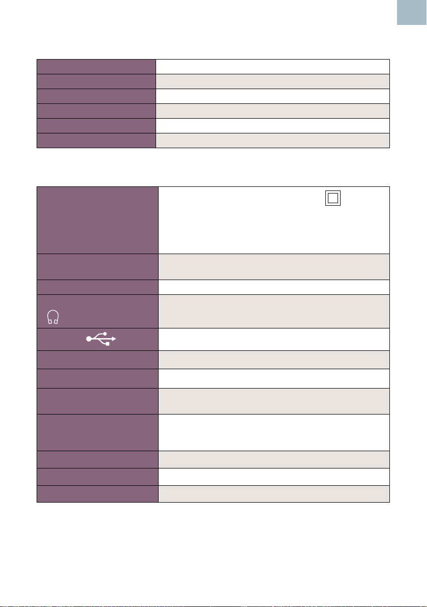
8.6 APPG Systolic Pressure Performance
Range 0 - 260 mmHg
Resolution 1 mmHg
Accuracy ± 3 mmHg
Indication Type On-Screen digital numeric display
Pressure Generation Bulb
Pressure Reduction Manual air release valve
8.7 General
EN
Charger- ‘R’ models only
(Part No.; 772559)
Max. Audio Output
(Loudspeaker)
Auto shut-off 1 minute obstetric, 3 minutes vascular
Headphone output Max. output Power: 25 mW rms (32Ω)
USB Port
SD Card Slot Micro SD
Real Time clock battery RENATA CR1025, 3V Lithium
Battery Type LR6 (Alkaline cells 1.5V)
Battery Life Typically, 500 x 1 minute examinations
Size Length: 140mm Height: 33mm Width: 75mm
Weight 280g
Service Life 7 years
Protection : Class II
Input Voltage : 100-240 V AC ±10%
Output Voltage : 5VDC ± 5%
Input Frequency : 50 - 60Hz
Standby power consumption: 230V AC ≤ 0.1W
500mW rms typical
Connector: 3.5mm stereo jack socket
Micro USB
HR6 (NIMH rechargeable 1.2V)
Note : Battery life is typically 2 years or 500 charge/
discharge cycles
Instructions For Use
49
Page 50

EN
8.8 Environmental
Operating
Temperature range +5°C to +40°C
Relative Humidity 15% to 90% (non condensing)
Pressure 700hPa to 1060hPa
Transport and Storage between uses
Without relative humidity control -25°C to +5°C
At a relative humidity of up to 90% non-condensing +5°C to +35°C
At a water vapour pressure up to 50hPa >+35°C to +70°C
8.9 Standards Compliance
IEC 60601-1: 2005 +A1:2012 (Edition 3.1) JIS T 060606-1:2012
ANSI/AAMI ES 60601-1:2005. IEC 60601-1-2:2007
CAN/CSAC22.2 No 601.1-M90 (R2005) IEC60601-1-11: 2015
IEC 60601-1:1998+A2:1995 (2nd Edition) BS EN 81060-1:2012
EN 60601-2-37:2008+A11:2011 - Thermal Indices (TI) and Mechanical Index (MI)
are below 1.0 for all device settings.
50
Instructions For Use
Page 51
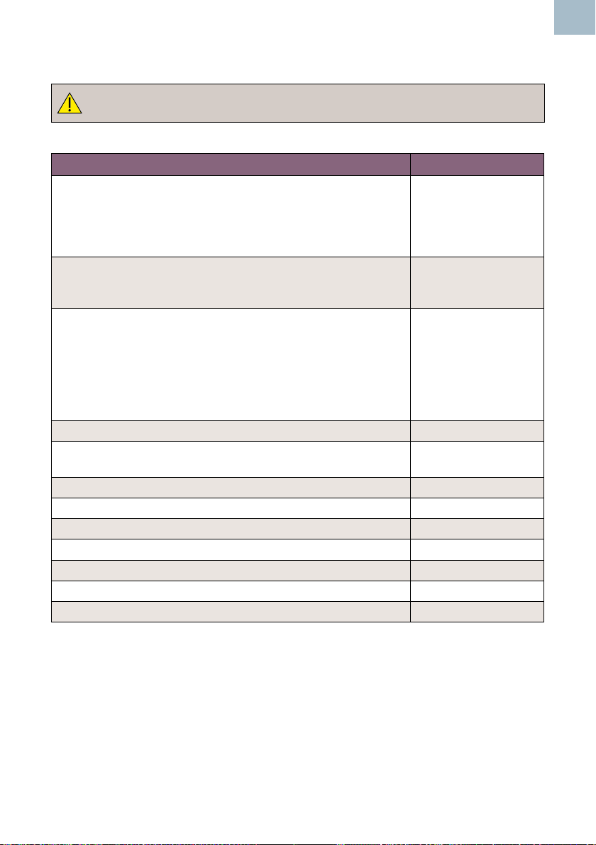
8.10 Accessories
Use only recommended accessories listed in this manual. .
Item Part No
ATP Kit (DMXR, Battery charger, EZ8XS, APPG probe and
adaptor, Pack of Adhesive strips (ACC179), 2 x Toe cuffs
(1 large + 1 small), Arm/Ankle cuff (23-33cm), Large Arm/
ankle cuff (31-40cm), DS-65 sphygmomanometer, tubes,
Gel, Neuropen, Box of Neuropen tips, Carry Case)
ABI Kit (DMXR, VP5XS, EZ8XS, Arm/Ankle cuff
(23-33cm), Large Arm/ankle cuff (31-40cm), DS-65
sphygmomanometer, Gel, Carry Case)
Vascular Probes : VP4XS
VP5XS
VP8XS
VP10XS
EZ8XS
PPG Adaptor
PA8XS Adaptor
Intraoperative Probe Starter pack ISP3XS
Obstetric Probes: OP2XS
OP3XS
Aquasonic 100 Gel ACC24
Support Stand ACC52-2
Micro SD Card ACC227
Mains Charger Kit ACC226
Carry Pouch ACC34
Headphones ACC21
Protective Pouch (IPX2) ACC-OBS-080
ATP KIT
ABI KIT
VP4XS
VP5XS
VP8XS
VP10XS
EZ8XS
PPGA1
PA8XS
OP2XS
OP3XS
EN
Instructions For Use
51
Page 52

EN
9. Electromagnetic Compatibility
Make sure the environment in which the Doppler is installed is not subject to strong sources of
electromagnetic interference (e.g. radio transmitters, mobile phones).
This equipment generates and uses radio frequency energy. If not installed and used properly, in
strict accordance with the manufacturer’s instructions, it may cause or be subject to interference.
Type-tested in a fully congured system, complies with IEC 60601-1-2, the standard intended
to provide reasonable protection against such interference. Whether the equipment causes
interference may be determined by turning the equipment off and on. If it does cause or is affected
by interference, one or more of the following measures may correct the interference:
• Reorienting the equipment
• Relocating the equipment with respect to the source of interference
• Moving the equipment away from the device with which it is interfering
• Plugging the equipment into a different outlet so that the devices are on different branch
circuits
WARNING: The use of accessories, transducers and cables other than those
specied,withtheexceptionoftransducersandcablessoldbythemanufacturer
of the Doppler as replacement parts for internal components, may result in
increased emissions or decreased immunity of the Doppler.
WARNING: The Doppler should not be used adjacent to or stacked with other
equipment and that if adjacent or stacked use is necessary, the Doppler should be
observedtoverifynormaloperationinthecongurationinwhichitwillbeused
WARNING: Portable RF communications equipment (including peripherals
such as antenna cables and external antennas) should be used no closer than
30cm(12inches)toanypartoftheDopplerincludingcablesspeciedbythe
manufacturer. Otherwise, degradation of the performance of this equipment could
result.
Guidance and Manufacturer’s declaration - electromagnetic emissions
DMX and SRX with OP2XS, OP3XS, VP4XS, VP5XS, VP8XS, EZ8, VP10XS, SR2 and SR3
The Doppler is intended for use in the electromagnetic environment specied below. The customer or the
user of the Doppler should assure that it is used in such an environment.
Emissions Test Compliance Electromagnetic Environment - guidance
RF emissions
CISPR 11
RF emissions
CISPR 11
Harmonic emissions
IEC 61000-3-2
Voltage uctuations /
icker emissions
IEC 61000-3-3
Group 1
Class B
Class A
Complies
The Doppler uses RF energy only for its internal function.
Therefore, its RF emissions are very low and are not likely to
cause any interference in nearby electronic equipment.
The Doppler is suitable for use in all establishments, including
domestic establishments and those directly connected to the
public low-voltage power supply network that supplies buildings
used for domestic purposes.
52
Instructions For Use
Page 53
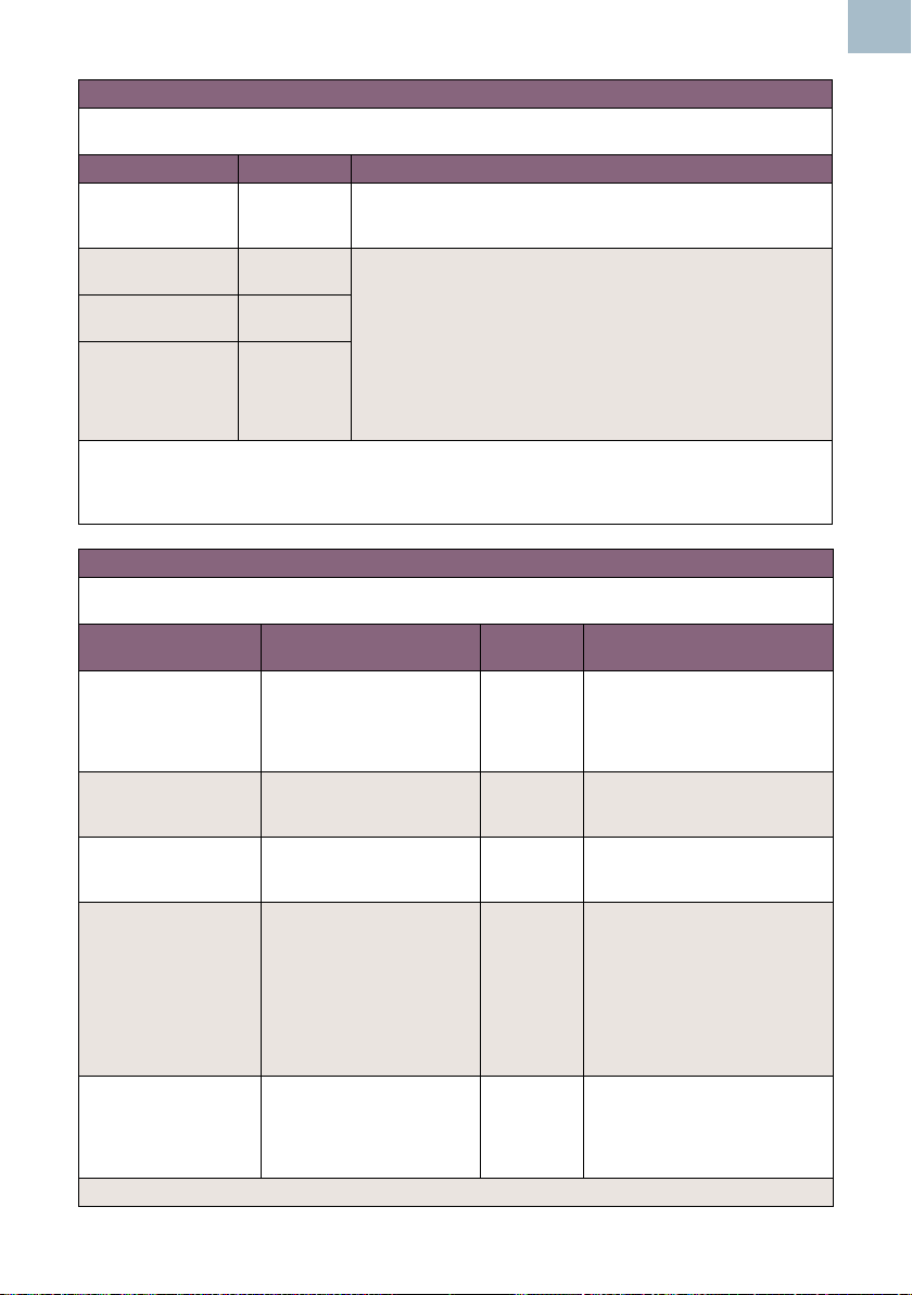
Guidance and Manufacturer’s declaration - electromagnetic emissions - DMX with IOP8
The Doppler is intended for use in the electromagnetic environment specied below. The customer or the
user of the Doppler should assure that it is used in such an environment.
Emissions Test Compliance Electromagnetic Environment - guidance
RF emissions
CISPR 11
RF emissions
CISPR 11
Harmonic emissions
IEC 61000-3-2
Voltage uctuations /
icker emissions
IEC 61000-3-3
NOTE: The EMISSIONS characteristics of this equipment make it suitable for use in industrial areas and
hospitals (CISPR 11 Class A). If it is used in a residential environment (for which CISPR 11 Class B is
normally required) this equipment might not offer adequate protection to radio-frequency communication
services. The user might need to take mitigation measures, such as relocating or re-orienting the equipment.
Group 1
Class A
Class A
Complies
The Doppler uses RF energy only for its internal function. Therefore,
its RF emissions are very low and are not likely to cause any
interference in nearby electronic equipment.
The Doppler is suitable for use in all establishments other than
domestic, and may be used in domestic establishments and those
directly connected to the public low-voltage power supply network
that supplies buildings used for domestic purposes, provided the
following warning is heeded:
Warning: This equipment/system is intended for use by healthcare
professionals only. This equipment/system may cause radio
interference or may disrupt the operation of nearby equipment. It
may be necessary to take mitigation measures, such as re-orienting
or relocating the Doppler or shielding the location
Guidance and Manufacturer’s declaration - electromagnetic immunity
The Doppler is intended for use in the electromagnetic environment specied below. The customer or the
user of the Doppler should assure that it is used in such an environment.
Immunity Test IEC 60601 test level
Electrostatic discharge
(ESD) IEC 61000-4-2
Electrical fast transient
burst
IEC 61000-4-4
Surge
IEC 61000-4-5
Voltage dips, short
interruptions and
voltage variations on
power supply input lines
IEC 61000-4-11
Power frequency
(50/60Hz) magnetic eld
IEC 61000-4-8
NOTE Ur is the a.c. mains voltage prior to the application of the test level.
± 8kV contact
± 15kV air
± 2 kV for power supply lines
± 1 kV for input/ output lines
± 1 kV line(s) to line(s)
± 2 kV line(s) to earth
0% Ur ; 0.5 cycles:
At 0°, 45°, 90°, 135°, 180°,
225°, 270° and 315°.
0% Ur ; 1 cycle: and
70% Ur ; 25/30 cycles, single
phase at 0°
0% Ur ; 250/300 cycles
30 A/m 30 A/m Power frequency magnetic elds
Compliance
level
8kV
15kV
2kV
1kV
1kV
2kV
Complies Mains power quality should be
Electromagnetic Environment guidance
Floors should be wood, concrete
or ceramic tile. If oors are
covered with synthetic material,
the relative humidity should be at
least 30%.
Mains power quality should be
that of a typical commercial or
hospital environment.
Mains power quality should be
that of a typical commercial or
hospital environment.
that of a typical commercial or
hospital environment. If the user
of the Doppler requires continued
operation during power mains
interruptions, it is recommended
that the Doppler is powered from
an uninterruptible power supply
or battery.
should be at levels characteristic
of a typical location in a
typical commercial or hospital
environment.
Instructions For Use
EN
53
Page 54
EN
Guidance and Manufacturer’s declaration - electromagnetic immunity
The Doppler is intended for use in the electromagnetic environment specied below. The customer or the
user of the Doppler should assure that it is used in such an environment.
Immunity Test
Conducted RF
IEC 61000-4-6
IEC 60601 test
level
3 Vrms
150kHz to 80MHz
outside ISM
a
bands
6 Vrms
150 kHz to 80
MHz in ISM and
amateur radio
bands
Compliance
level
3V
6V
Electromagnetic Environment - guidance
Portable and mobile RF communications equipment
should be used no closer to any part of the Doppler,
including cables, than the recommended separation
distance calculated from the equation applicable to
the frequency of the transmitter.
d = 1.2 √ P
d = 2.0 √ P
Radiated RF
IEC 61000-4-3
10 V/m
80MHz to 2.7MHz
10V/m
d = 1.2 √ P
d = 2.3 √ P
80MHz to 800MHz
800MHz to 2.7GHz
where P is the maximum output power rating of the
transmitter in watts (W) according to the transmitter
manufacturer and d is the recommended separation
distance in metres (m).
b
Field strengths from xed RF transmitters, as
determined by an electromagnetic site survey, c
should be less than the compliance level in each
frequency range d.
Interference may occur in the vicinity of the
equipment marked with the following symbol:
NOTE 1 At 80MHz and 800MHz, the higher frequency range applies.
NOTE 2 These guidelines may not apply in all situations. Electromagnetic propagation is affected by
absorption and reection from structures, objects and people.
a
The ISM (industrial, scientic and medical) bands between 150 kHz and 80 MHz are 6,765 MHz, to 6,795
MHz; 13,553 MHz to 13,567 MHz; 26,957 MHz to 27,283 MHz; and 40,66 MHz to 40,70 MHz.
b
The compliance levels in the ISM frequency bands between 150 kHz and 80 MHz and in the frequency
range 80 MHz to 2,5 GHz are intended to decrease the likelihood that mobile/portable communications
equipment could cause interference if it is inadvertently brought into patient areas. For this reason, an
additional factor of 10/3 is used in calculating the recommended separation distance for transmitters in these
frequency ranges.
c
Field strengths from xed transmitters, such as base stations for radio (cellular/cordless) telephones
and land mobile radios, amateur radio, AM and FM radio broadcast and TV broadcast cannot be predicted
theoretically with accuracy. To assess the electromagnetic environment due to xed RF transmitters, an
electromagnetic site survey should be considered. If the measured eld strength in the location in which the
Doppler is used exceeds the applicable RF compliance level above, the Doppler should be observed to verify
normal operation. If abnormal performance is observed, additional measures may be necessary, such as reorienting or relocating the Doppler.
d
Over the frequency range 150kHz to 80kHz, eld strengths should be less than 3V/m.
54
Instructions For Use
Page 55

Recommended separation distances between portable and mobile RF communications equipment
and the Doppler
The Doppler is intended for use in an electromagnetic environment in which radiated RF disturbances are
controlled. The customer or user of the Doppler can help prevent electromagnetic interference by maintaining
a minimum distance between portable and mobile RF communications equipment (transmitters) and the
Doppler as recommended below, according to the maximum output power of the communications equipment.
Rated maximum
output power of
transmitter
W
0.01 0.12 0.12 0.23
0.1 0.38 0.38 0.73
1 1.2 1.2 2.3
10 3.8 3.8 7.3
100 12 12 23
For transmitters rated at a maximum output power not listed above, the recommended separation distance d
in metres (m) can be estimated using the equation applicable to the frequency of the transmitter, where P is
the maximum output power rating of the transmitter in watts (W) according to the transmitter manufacturer.
NOTE 1 At 80MHz and 800MHz, the separation distance for the higher frequency range applies.
NOTE 2 These guidelines may not apply in all situations. Electromagnetic propagation is affected by
absorption and reection from structures, objects and people.
Separation distance according to frequency of transmitter
m
150kHz to 80MHz
d = 1.2 √ P
80MHz to 800MHz
d = 1.2 √ P
800MHz to 2.5GHz
d = 2.3 √ P
EN
9.1 ManufacturersPerformanceCriteriaSpecication
The essential performance is derived from the Particular standard IEC 60601-2-37 for
diagnostic ultrasound devices.
Requirement Sub-Clause
Free from noise on a waveform or artefacts or distortion in an image
or error of a displayed numerical value which cannot be attributed to
a physiological effect and which may alter the diagnosis.
Free from the display of incorrect numerical values associate with the
diagnosis to be performeda.
Free from the unintended or excessive ultrasound output. 201.10.101
Free from the production of unintended or excessive TRANSDUCER
ASSEMBLY surface temperature.
“incorrect” in the sense that the displayed value differs from what is calculated (having been
a
altered during data transfer), or the calculation itself is not correct.
Instructions For Use
202.6.2.1.10
202.6.2.1.10
202.6.2.1.10
202.6.2.1.10
55
Page 56

EN
10. End of Life Disposal
This symbol signies that this product, including its accessories and consumables
is subject to the WEEE (Waste Electrical and Electronic Equipment) regulations and
should be disposed of responsibly in accordance with local procedures.
56
Instructions For Use
Page 57

11. Warranty & Service
Huntleigh Healthcare Diagnostic Products Division standard terms and conditions apply
to all sales. A copy is available on request. These contain full details of warranty terms
and do not limit the statutory rights of the consumer.
Service Returns
If for any reason the Doppler has to be returned, please:
• Clean the product following the instructions in this manual.
• Pack it in suitable packing.
• Attach a decontamination certicate (or other statement declaring
that the product has been cleaned) to the outside of the package.
• Mark the package ‘Service Department ‘.
For further details, refer to NHS document HSG(93)26 (UK only).
Huntleigh Healthcare Ltd reserve the right to return product that does not contain a
decontamination certicate.
Service Department.
Huntleigh Healthcare, Diagnostic Products Division,
35, Portmanmoor Rd.,
Cardiff. CF24 5HN
United Kingdom.
EN
Tel: +44 (0)29 20485885
Fax: +44 (0)29 20492520
Email: [email protected]
[email protected]
www.huntleigh-diagnostics.com
Instructions For Use
57
Page 58
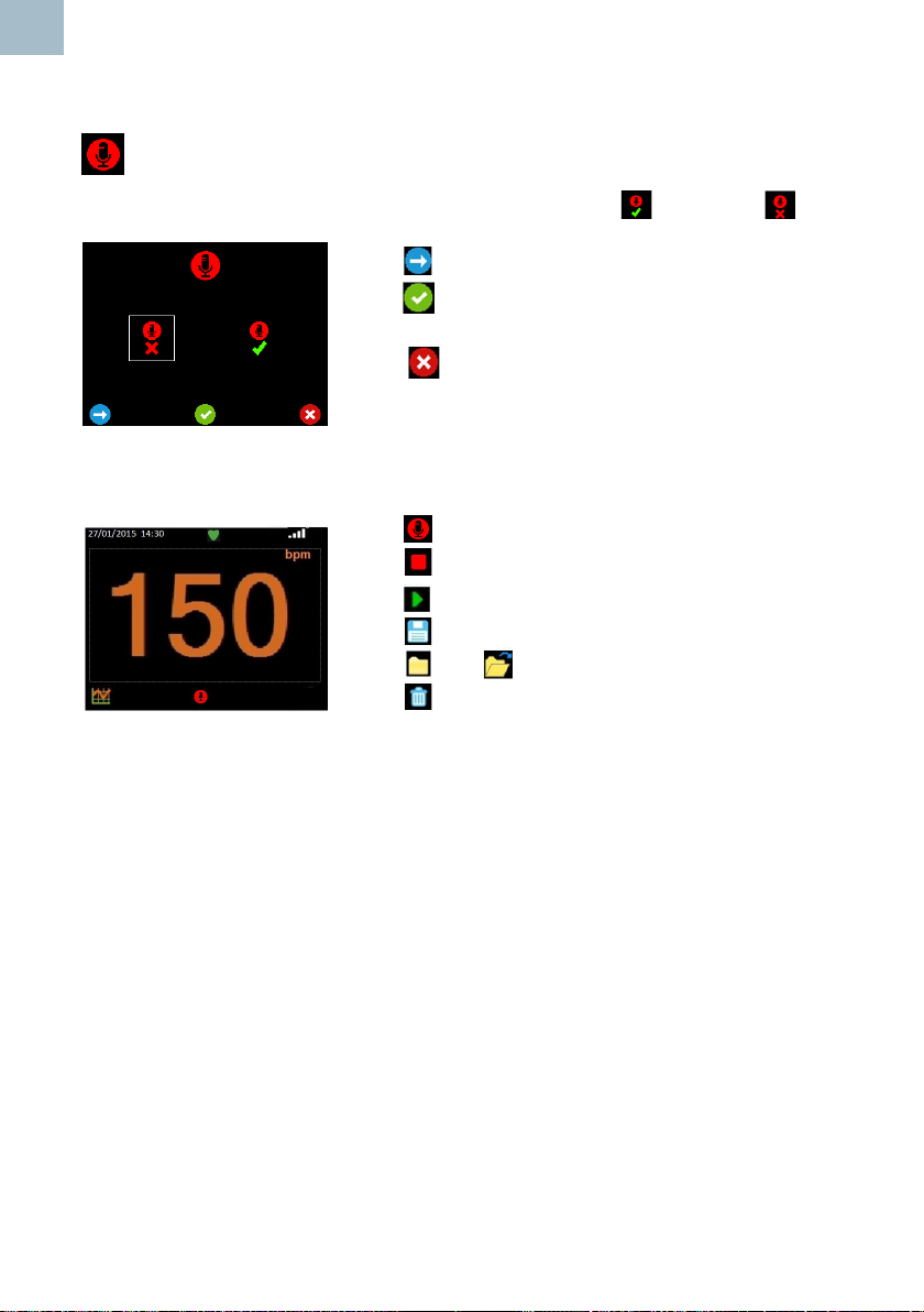
EN
12. Additional Obstetric Features
Fetal Heart Audio Record Screen
This screen allows Fetal Heart audio recording to be enabled or disabled .
Press to move the highlight between selections.
Press to accept your selection and return to the
Setup screen.
Press to return to the Setup screen without saving
the changes.
Record Function
Press to start recording sound.
Press to stop recording sound.
Press to playback sound.
Press to save the recording.
Press and to access stored recordings.
Press to delete the recording.
58
Instructions For Use
Page 59
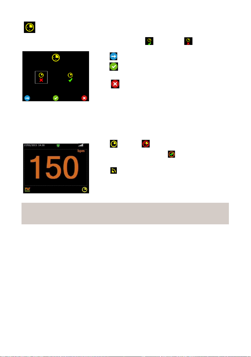
Timer Selection Screen
This screen allows a 15 minute timer to be enabled or disabled .
Press to move the highlight between selections.
Press to accept your selection and return to the
Setup screen.
Press to return to the Setup screen without saving
the changes.
Timer Function
A timer is available to remind the clinician to repeat auscultation after 15 minutes if
required.
Press to set or to cancel the timer.
When the timer expires, press to acknowledge and
silence the 15 minute timer.
Press to switch the Doppler off.
Note
The timer will repeat every 15 minutes until cancelled, even if the Doppler has
been switched off.
Page 60

If a serious incident occurs in relation to this medical device, affecting the user, or the patient then the user or
patient should report the serious incident to the medical device manufacturer or the distributor.
In the European Union, the user should also report the serious incident to the Competent Authority in the
member state where they are located.
Manufactured in the UK by Huntleigh Healthcare Ltd on behalf of;
ArjoHuntleigh AB
Hans Michelsensgatan 10
211 20 Malmö, Sweden
Huntl eigh Healthca re Ltd.
35 Portmanmoor Road, Cardiff, CF24 5HN, United Kingdom
T: +44 (0)29 20 48588 5 sales@hun tleigh-di agnostics .co.uk
www.huntleigh -diagnos tics.com
Registered No: 942245 England & Wales. Registered Office:
ArjoH untleigh House, Houghton Hall Business Park , Houghton Regis, Bedfordshir e, LU5 5XF
©Huntleigh Healthcare Limited 2015
A Member of the Arjo Family
® and ™ are trademarks of Huntleigh Technology Limited
As our policy is one of continuous improveme nt, we reserve the right to modify d esigns without prior notice.
11/2020772484EN-21
AW:: 1001048-2
(ENGLISH)
 Loading...