

Hunter Douglas Window Fashions STK Users Manual
Installation • Operation • Care
Duette® Honeycomb Shades
PowerView® Motorization

CONTENTS
Getting Started:
Product View ................................................................ 1
Tools and Fasteners Needed
.......................................... 2
Installation:
Installation Overview .................................................... 3
STEP 1 — Install the Brackets
Mount the Installation Brackets — Inside Mount
Mount the Installation Brackets — Outside Mount
Mount the Installation Brackets — EndMount
STEP 2 — Install the Shade
STEP 3 — Connect the Power Source
....................................... 3
............. 4
.......... 7
................ 9
........................................ 10
.......................... 11
Operation:
Testing the Shade ....................................................... 15
Using the PowerView
Resetting the Shade, If Necessary
Level the Rail(s), If Necessary
Troubleshooting
®
Remote ..................................... 15
................................ 18
....................................... 19
.......................................................... 20
Care:
Removing the Shade, If Necessary ............................... 22
Cleaning Procedures
................................................... 22
Declarations .............................................................. 24
Warranty .........................................................Back Cover
Questions?
Call Hunter Douglas Consumer Support at
1-888-501-8364.
© 2017 Hunter Douglas. All rights reserved. All trademarks used herein are the property of Hunter Douglas or
their respective owners.
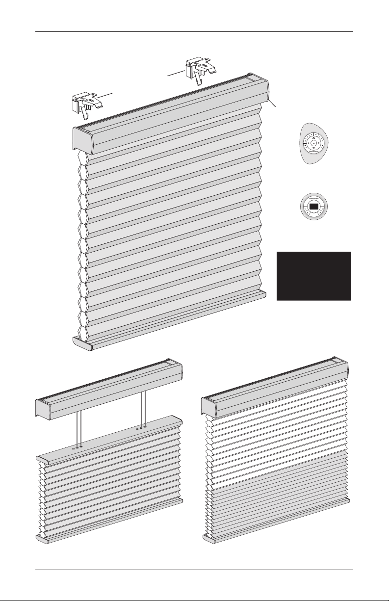
Product View
Installation Brackets
with Spacer Blocks
GETTING STARTED
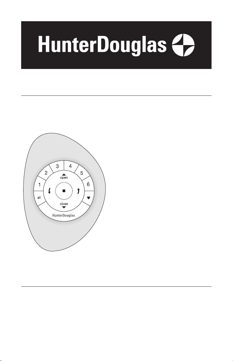
Manual
Control
Button
and
LED
PowerView
Standard
®
PowerView Remote
(with Pebble
PowerView Scene
Controller (with Surface)
®
)
select
PowerView App
Top-Down and
Top-Down/Bottom-Up
Duolite
™
1
GETTING STARTED
Thank you for purchasing Hunter Douglas Duette® honeycomb shades with PowerView®
Motorization. With proper installation, operation, and care, your new shades will provide years of
beauty and performance.
Please thoroughly review this instruction booklet and the enclosed packing list before beginning
the installation.
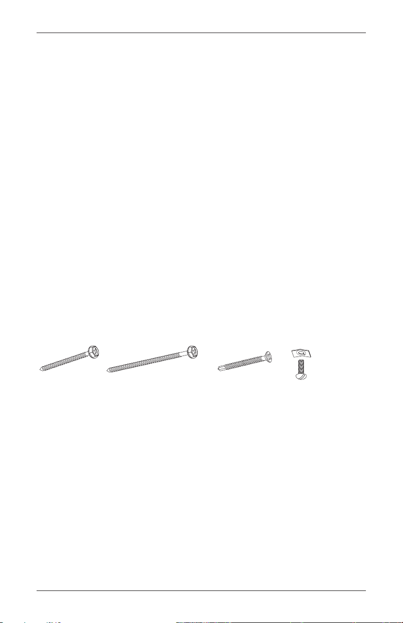
Tools and Fasteners Needed
■ Flat blade and Phillips screwdrivers
■ Level (laser level is recommended)
■ Measuring tape and pencil
■ Power drill, 3/32" drill bit, and 1/4" hex driver
In addition, you will need fasteners designed to work with your specific mounting surface(s).
■ #6 Hex Head Screws (Provided). Two 11/2" screws are provided per installation bracket.
■ Longer #6 Hex Head Screws (Not Provided). If using spacer blocks, use #6 screws long
enough for a secure attachment.
■ #6 Flat Head Screws (Provided). If end mounting the shade, use two 11/2" screws per
installation bracket.
■ Speed Nuts and Screws (Provided). Extension brackets come with speed nuts and screws.
■ Drywall Anchor (Not Provided). Use drywall anchors when mounting into drywall.
#6 x 11/2"
Hex Head Screw
(Provided)
2
Longer #6 Hex Head Screw
for Use with Spacer Blocks
(Not Provided)
#6 Flat Head Screw
for Use with End Mounts
(Provided)
Speed Nut
and Screw
(Two Provided with
Each Extension Bracket)
Installation Overview
Shade
Width
Brackets
Required
12" – 36" 2
36
1
/8" – 72" 3
72
1
/8" – 108" 4
108
1
/8" – 144" 5
144
1
/8" – 174" 6
1
/2" Spacer Block
1
/8" Shim
Installation
End Mount
To install your shade, you will need to perform the following three steps:
STEP 1: Install the Brackets
STEP 2: Install the Shade
STEP 3: Connect the Power Source
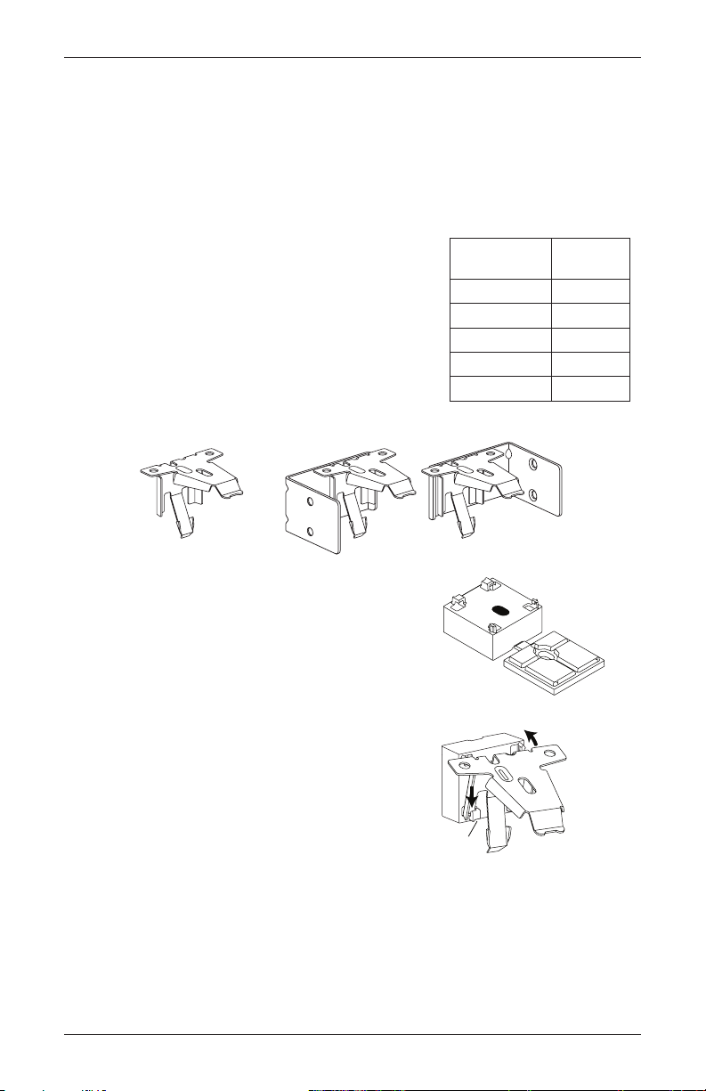
STEP 1 — Install the Brackets
■ Your order will include the correct number of installation
brackets for your shade width, as shown in the table.
➤ There are two sizes of installation brackets, one for 3/8"
3
/4" pleat sizes and a larger one for 11/4" pleat size.
and
➤ For end mounts, two brackets are used up to the
maximum width of 72".
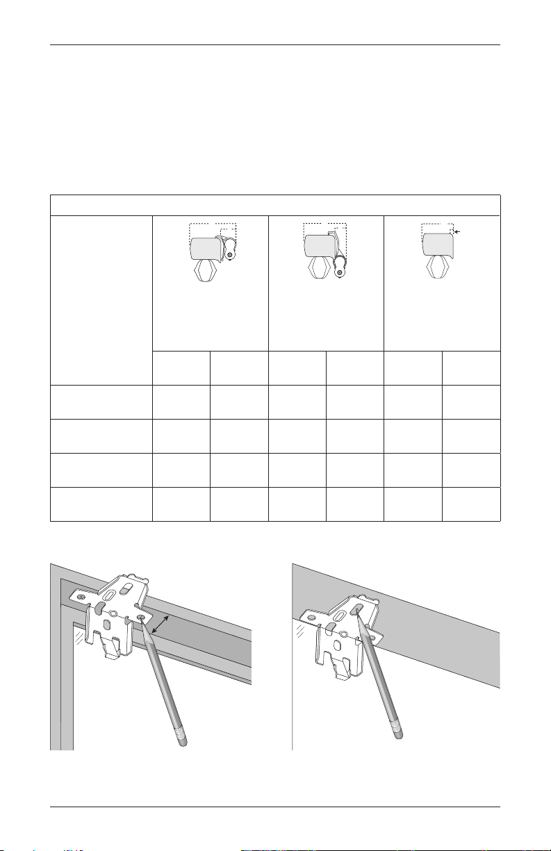
INSTALLATION
IMPORTANT: A
using an attached battery wand. The spacer block is
pre-attached to the back of the installation bracket.
Bracket
1
/2" spacer block is required for shades
■ Should the spacer block become detached, reattach it.
➤ Insert the legs of the installation bracket into the
tabs onthespacer block.
➤ Rotate the installation bracket back, asshown, to
snap it in place.
Brackets
Tab
3
INSTALLATION
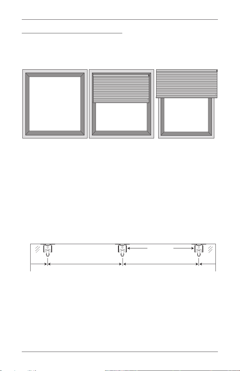
Mounting Types and Window Terminology
If the installation brackets are mounted correctly, the rest of the installation process follows
easily. To prepare for this important first step, review the mounting types and basic window
terminology illustrated below.
Molding
Head Jamb
Jamb Jamb
Collectively, the sill and
jambs are called the
“window casement.”
Sill
Inside Mount
Shade fits within
window opening.
■ Refer to the appropriate page below based on your order:
➤ Inside Mount — Below
➤ Outside Mount — Page 7
➤ End Mount — Page 9
Outside Mount
Shade mounts outside
window opening.
Mount the Installation Brackets — Inside Mount
■ Mark 2" in from each jamb for bracket location.
➤ If more than two installation brackets came with your order, space additional bracket(s)
evenly between the two end brackets. Allow a minimum of 15" between the
brackets at the motor end for the battery wand. Mount into wood whenever possible.
Minimum 15"
for Battery Wand
2" Space Evenly
Jamb Jamb
4
Space Evenly
2"
INSTALLATION
A
B
A
B
A
B
A
B
B
B
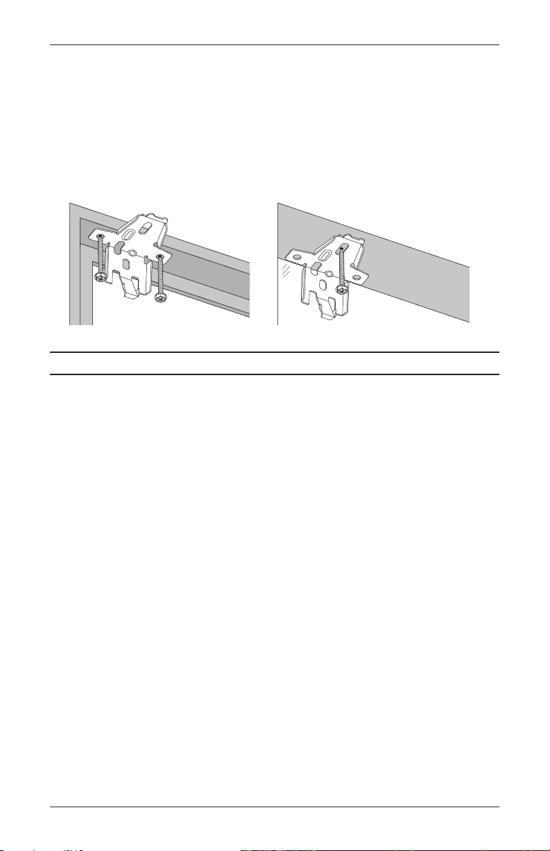
■ Center the brackets on your marks, then mark each of the screw holes.
➤ Mounting depths vary depending on the fabric pleat size. See the following chart for
minimum and fully recessed depth requirements (measured from the front of the sill to
the back of the installation bracket).
➤ Mark both winged screwholes with shallow mounting depths.
➤ Mark the center screw hole when depth permits. The center hole requires 11/2".
Mounting Depth Requirements
Minimum mounting
depth: Inside Mount (A)
Minimum mounting
depth: End Mount
Minimum mounting
depth: Flush Mount (B)
Minimum flat vertical
surface: Outside Mount
Pleat Size:
A
Battery Wand
High Mount Bracket
(Standard)
Battery Wand
Low Mount Bracket
A
(Optional)
Satellite Battery Pack,
C-Size Battery Wand,
18V DC Power Supply,
or Large DC Power
Supply
3
3
/8",
/4" 11/4"
1" 1" 1"
3
/4" 13/4" 13/4" 13/4" 11/4" 11/4"
1
3
/4" 31/2" 25/8" 33/8" 21/4" 31/8"
2
1
/4" 11/4" 11/4" 11/4" 11/4" 11/4"
1
3
3
/8",
/4" 11/4"
3
3
/8",
/4" 11/4"
1
1"
/2"
See Depth
Chart
Use Center Hole
When Depth Permits
1
/2"
5
INSTALLATION
■ Drill the screw holes using a 3/32" drill bit.
CAUTION: Use drywall anchors when mounting into drywall.
■ Use a level to check that the mounting surface is level. Shim the brackets if necessary.
■ Attach the installation brackets using the screws provided.
IMPORTANT: The front edges of the installation brackets must be level and aligned. If
mounting to a heavily textured surface, shim the brackets, if needed.
Proceed to “STEP 2 — Install the Shade” on page 10.
6
INSTALLATION
Headrail End Marks
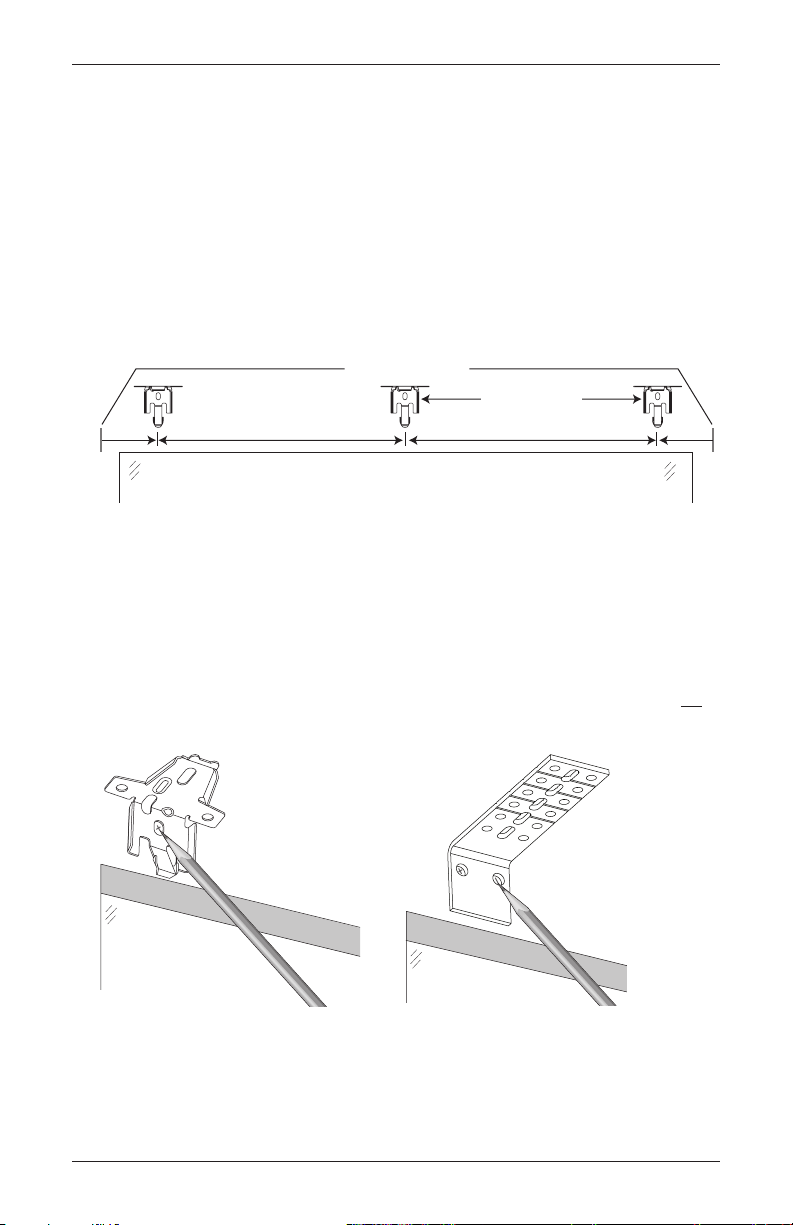
Mount the Installation Brackets — Outside Mount
■ Center the headrail over the window opening at the desired height. Use a pencil to lightly
mark the wall at each end of the headrail.
➤ Alternatively, measure the width of the headrail and use that width to mark the headrail
end points over the window opening.
■ Mark 2" from each end of the headrail.
➤ If more than two installation brackets came with your order, space them evenly between
the two end brackets and mark their location. Allow a minimum of 15" between the
brackets at the motor end for the battery wand. Mount into wood whenever possible.
Minimum 15"
for Battery Wand
2" Space Evenly Space Evenly
Window Opening
■ Center the brackets on your marks, then mark each of the screwholes.
➤ A minimum of 11/4" flat vertical surface is required to mount the brackets.
➤ The top of the installation brackets or extension brackets should be at the desired shade
height. The brackets should be level and aligned.
➤ When using extension brackets, mark two screw holes per bracket.
CAUTION: The rear of the brackets must be flush against a flat mounting surface. Do not
mount brackets oncurved molding.
2"
■ Drill the screw holes using a 3/32" drill bit.
CAUTION: Use drywall anchors when mounting into drywall.
7
 Loading...