

Page 1

OPERATION INSTRUCTIONS
Supersedes Form 4202T, 07-05
Form 4202T, 11-05
GSP9700 Series
Road Force Measurement
System
With SmartWeight™ Balancing Technology
Software Version 5.0
Copyright 1997-2005 Hunter Engineering Company
Page 2

OWNER INFORMATION
Model Number ____________________________________________________________________
Software Version Number ___________________________________________________________
Serial Number ____________________________________________________________________
Date Installed_____________________________________________________________________
Service and Parts Representative _____________________________________________________
Phone Number____________________________________________________________________
Sales Representative_______________________________________________________________
Phone Number____________________________________________________________________
Concept and Procedure Training Checklist
Trained
Safety Precautions
Quick-Thread
Autostart
Servo-Stop
Maintenance & Calibration
Cleaning, Lubrication, and Maintenance of Adaptors, Hub, and Shaft
Calibrating the Balancer
Calibrating the Load Roller and Dataset Arms
Calibrating the Inflation Station
Mounting the Wheel/Tire Assembly
Verifying Mounting Repeatability with Centering Check® Feature
Cone Mounting
Pressure Ring and Spacers
Flange Plate and Cone Mounting
Wheel Balancing
SmartWeight™
Standard
Mixed Weights
Adhesive Weights with Auto Dataset Arms
Split-Spoke
Patch Balancing with Auto Dataset Arms (optional)
Declined
Do’s and Don’ts of Wheel Balancing
Road Force Measurement and ForceMatching™
Adjusting P/SUV/LT Limits
Assembly Measurements
Applying Previous Wheel Measurements
Applying Previous Tire Measurements
Wheel Measurement with Dataset Arms
Tire Installed
Bare Rim
Road Force Measurement First Harmonic Diagnosis Screen
“Current Runout and Force Variation”
“Diagnosis Explanation” and “Details” Screens
Match Codes
MatchMaker Procedure Explained
Do’s and Don’ts of Road Force Measurement
Page 3

Individuals and Date Trained
__________________________________ __________________________________
__________________________________ __________________________________
__________________________________ __________________________________
__________________________________ __________________________________
__________________________________ __________________________________
__________________________________ __________________________________
Page 4

Page 5

CONTENTS
1. GETTING STARTED........................................................................................1
1.1 Introduction.................................................................................................................1
1.2 For Your Safety ........................................................................................................... 1
Hazard Definitions.................................................................................................. 1
IMPORTANT SAFETY INSTRUCTIONS
Electrical.................................................................................................................3
Decal Information and Placement.......................................................................... 4
Right Side View...............................................................................................4
Left Side View..................................................................................................5
Back View........................................................................................................6
Specific Precautions/Power Source....................................................................... 7
Turning Power ON/OFF......................................................................................... 7
Equipment Installation and Service .......................................................................8
Equipment Specifications....................................................................................... 8
Electrical.......................................................................................................... 8
Air .................................................................................................................... 8
Atmospherics...................................................................................................8
Sound Pressure Level..................................................................................... 8
Safety Summary ....................................................................................................8
Explanation of Symbols...................................................................................8
1.3 Equipment Components ............................................................................................ 9
Standard Balancer Accessories........................................................................... 10
1.4 Operating the Console ............................................................................................. 11
Using Softkeys.....................................................................................................11
Primary Balancing Display................................................................................... 12
Using the Control Knob (GSP9712).....................................................................12
Using Control Knobs (GSP9702).........................................................................13
Resetting the Program......................................................................................... 13
Using the Screen Saver/Merchandising Display..................................................13
........................2
2. BALANCING OVERVIEW..............................................................................15
2.1 Balancing Modes ......................................................................................................15
SmartWeight™ Balancing Technology................................................................ 15
Balancing Theory................................................................................................. 15
Static Imbalance............................................................................................ 15
Couple Imbalance..........................................................................................16
Static and Dynamic Imbalance Sensitivity........................................................... 17
2.2 Identifying the Static Balance Weight Plane.......................................................... 18
2.3 Identifying the Dynamic Balance Weight Planes................................................... 19
2.4 SmartWeight™ Dynamic Weight Planes ................................................................ 20
3. MOUNTING WHEELS ON THE BALANCER ................................................21
3.1 Mounting the Wheel Using Wheel Lift (Optional) .................................................. 21
Raising the Tire/Wheel Assembly........................................................................21
Lowering the Tire/Wheel Assembly.....................................................................23
3.2 Mounting the Wheel (Without Wheel Lift)...............................................................23
Mounting Error Detection Features...................................................................... 24
Front/Back Cone Mounting..................................................................................24
Using Plastic Wheel Mounting Washer................................................................26
Cone/Flange Plate Mounting ............................................................................... 27
Expandable Collet Mounting................................................................................28
Using the Pressure Ring and Spacers................................................................. 28
Pressure Ring................................................................................................28
Spacers .........................................................................................................29
CenteringCheck®..................................................................................................30
3.3 On-Vehicle Wheel Mounting Methods ....................................................................33
Hub Centric..........................................................................................................33
Lug Centric........................................................................................................... 33
GSP9700 Series Road Force Measurement System Operation Contents i
Page 6

4. BALANCING A WHEEL................................................................................. 35
4.1 Balancing Procedures.............................................................................................. 35
SmartWeight™ Balancing Technology................................................................ 35
Using SmartWeight™....................................................................................35
Switching from SmartWeight™ to Traditional Dynamic Balancing Modes....37
Dynamic Balancing Selection ..............................................................................37
Static Balancing Selection ...................................................................................37
Static Balance Mode Reminder for “Dynamic Balance Importance” (Except
Patch Balance)..............................................................................................38
Selecting Weight Types and Placement Modes..................................................39
STANDARD Balancing Procedure (Using Clip-On Weights)........................39
MIXED WEIGHTS Balancing Procedure (Combination of Clip-On &
Adhesive Weights).........................................................................................41
ADHESIVE WEIGHTS Balancing Procedure (Adhesive Weights Only).......43
PATCH BALANCE® Procedure.....................................................................45
4.2 Using the Auto Dataset® Arms ................................................................................48
Automatic Weight Position Measurement............................................................48
Manual Weight Position Measurement................................................................ 48
Measuring Dimensions for Standard Clip-on Weight Balancing.......................... 49
Measuring Dimensions for Mixed Weights (Clip-on/Tape-on) Balance...............49
Measuring Dimensions for Adhesive Weights Balancing (Tape-on/Tape-on).... 50
Measuring 20 Inch or Larger Rims.......................................................................51
Adjustable Length Inner Dataset Arm ........................................................ 51
Servo-Aided Adhesive Weight Placement.....................................................51
Manual Adhesive Weight Placement.............................................................53
Rim Runout Measurements.................................................................................54
Single Arm Rim Runout External Measurement (Tire and Wheel Assembly)54
Dual Arm Rim Runout External Measurement (Tire and Wheel Assembly).54
Rim Runout Measurement (Bare Rim)..........................................................56
4.3 Primary and Popup Screens....................................................................................57
Primary Screen Selection ....................................................................................57
Balance Primary Screen......................................................................................58
4.4 Load Roller ................................................................................................................ 60
Load Roller Operation..........................................................................................60
4.5 ForceMatching™.......................................................................................................61
ForceMatching™ Procedures..............................................................................62
ForceMatching™ Using Previous Bare Rim Measurement.................................63
ForceMatching™ Using Previous Road Force™ Measurement.......................... 63
Using ForceMatch Codes Feature.......................................................................64
Dial Indicator Gauges Feature.............................................................................64
Lateral/Radial Rim High Spot Indicators Feature ................................................65
Details/Diagnosis Explanation Key......................................................................65
Encountering ForceMatching™ Prediction Errors ...............................................65
Do’s and Don’ts of Road Force Measurement.................................................. 66
4.6 QuickMatch™ Tire and Wheel Mounting................................................................ 66
QuickMatch™ Procedures...................................................................................67
QuickMatch™ Using Previous Bare Rim Measurement......................................68
QuickMatch™ Using Previous Loaded Runout Measurement............................68
Dial Indicator Gauges Feature.............................................................................68
Lateral/Radial Rim High Spot Indicators Feature ................................................69
Encountering ForceMatching™ or QuickMatching™ Prediction Errors...............69
Do’s and Don’ts of Loaded Runout Measurement............................................... 70
4.7 StraightTrak® LFM (Lateral Force Measurement) ..................................................70
Disabling StraightTrak®........................................................................................73
Vehicle Plan View ................................................................................................ 74
Net Tire Pull Arrow...............................................................................................74
Road Force Arrows...........................................................................................74
Changing Tag Numbers.......................................................................................75
Show Least Pull ................................................................................................... 76
Show Least Vibration........................................................................................... 76
Show Alternate Placements.................................................................................76
ii Contents GSP9700 Series Road Force Measurement System Operation
Page 7

Show Details........................................................................................................77
Determining Tire Conicity Outliers.................................................................77
Printout................................................................................................................. 77
Inflation Pressure................................................................................................. 78
4.8 Quick-Thread™ Feature...........................................................................................78
4.9 Motor Drive/Servo-Stop............................................................................................79
4.10 Spindle-Lok® Feature.............................................................................................. 79
4.11 Hood Autostart Feature..........................................................................................79
4.12 Loose Hub Detect Feature ..................................................................................... 79
4.13 Blinding and Rounding ..........................................................................................80
4.14 Inflation Station.......................................................................................................81
5. BALANCING FEATURES AND OPTIONS ....................................................83
5.1 SmartWeight™ Balancing Technology................................................................... 83
5.2 WeightSaver™ Wheel Balancing Feature............................................................... 84
5.3 Quick-Thread™ Feature...........................................................................................84
5.4 Motor Drive/Servo-Stop............................................................................................85
5.5 Spindle-Lok® Feature................................................................................................ 85
5.6 Hood Autostart Feature............................................................................................86
5.7 Loose Hub Detect Feature ....................................................................................... 86
5.8 Inflation Station.........................................................................................................86
5.9 Split Weight® Feature ...............................................................................................87
Split Weight® Operation.......................................................................................87
Correcting Large Imbalances...............................................................................88
5.10 Split Spoke® Feature............................................................................................... 88
Hiding Adhesive Weight behind Spoke................................................................ 88
Re-entering Similar Wheel after Split Spoke® is Enabled.................................... 90
Placing Hidden Weight Inside of Hollow Spokes................................................. 91
5.11 MatchMaker™ Tire and Wheel Mounting Procedure........................................... 93
Tires Mounted on Rims........................................................................................93
Tires Not Mounted to Rims..................................................................................94
5.12 Diagnosis Explanation Screen (Limits Disabled)................................................95
5.13 Diagnosis Explanation Screen (Limits Enabled).................................................95
5.14 Details Screen.........................................................................................................96
5.15 Print Summary ........................................................................................................97
5.16 Harmonics & T.I.R. Data/Plots ............................................................................... 98
Assembly Data Plots Screen ............................................................................... 98
Tire Data Plots Screen.........................................................................................99
5.17 Statistics................................................................................................................100
Show Statistics................................................................................................... 100
Weight Savings..................................................................................................101
Rim Data Plots Screen....................................................................................... 102
6. EQUIPMENT INFORMATION ......................................................................103
6.1 Software Identification ........................................................................................... 103
6.2 Program Cartridge Removal and Installation.......................................................103
6.3 Balancer Set Up ......................................................................................................104
GSP9700 Series Road Force Measurement System Operation Contents iii
Setting Up the Display Language......................................................................105
Setting Up the Printout Language......................................................................105
Setting Up the QuickMatch® Feature.................................................................105
Setting Up the Use Limits Feature.....................................................................106
Setting Up the Screen Saver Time-out..............................................................106
Setting Up the Hood Autostart Feature.............................................................. 107
Setting Up the Servo-Stop/Servo-Push.............................................................107
Setting Up the Quick-Thread™ Feature............................................................108
Setting Up the Balance Check Spin...................................................................108
Setting Up the Weight Units...............................................................................108
Setting Up the Inflation Station Units................................................................. 109
Setting Up the Runout Units .............................................................................. 109
Setting Up the Road Force Units.......................................................................109
Setting Up the Prompted Inflation Station..........................................................110
Setting Up the Prompted Centering Checks......................................................110
Page 8

6.4 Service Mode Setup and Features ........................................................................ 111
Setting Up the Runout & Road Force Limits...................................................111
Setting the “P” Limits...................................................................................111
Setting the “P/SUV” Limits...........................................................................111
Setting the “LT” Limits .................................................................................112
Setting the Limits to “Factory Default”......................................................... 112
Programmed Road Force Limits...............................................................112
Setting Up the Balance Limits............................................................................113
Main Selections...........................................................................................113
Setting Up the Weight Units ........................................................................113
Setting Up the Ounce Round Amount.........................................................113
Setting Up the Gram Round Amount...........................................................113
Setting the Limits Displayed........................................................................113
Non-SmartWeight Options ..........................................................................113
Setting Up the Ounce Blind Amount............................................................113
Setting Up the Gram Blind Amount.............................................................113
SmartWeight™ Options - Setting Up the Force Limits................................114
WeightSaver™ Residual Goal.....................................................................114
Setting Up the Inner Dataset Arm Type.............................................................114
Setting Up the Console Type.............................................................................115
Setting Up the Load Roller Type........................................................................ 115
7. CALIBRATION AND MAINTENANCE......................................................... 116
7.1 Calibration Procedures .......................................................................................... 116
Balancer (3 Spin Procedure)..............................................................................117
Inner Dataset® Arm (Calibration Tool, 221-672-1, Required)............................118
Outer Dataset® Arm (Calibration Tool, 221-672-1, Required) ...........................121
Load Roller (Calibration Tool, 221-672-1, Required).........................................123
Servo-Stop.........................................................................................................125
Quick Calibration Check Procedure...................................................................126
7.2 Diagnostic Procedures...........................................................................................126
Force Sensors....................................................................................................127
Rotary Encoders ................................................................................................127
Keys and Switches.............................................................................................127
Data Acquisition Circuits....................................................................................127
Dataset® Arm Sensors.......................................................................................127
Loaded Runout Sensor......................................................................................127
7.3 Printing.....................................................................................................................127
Changing Ribbon Cartridge (P/N 162-42-2): ..................................................... 128
Bottom Feed Paper Loading..............................................................................128
7.4 Cleaning the Console .............................................................................................128
7.5 Spindle Hub Face and Shaft Maintenance ........................................................... 129
7.6 Mounting Cone Maintenance.................................................................................129
8. THEORY OF OPERATION ..........................................................................131
8.1 Harmonic Vibrations...............................................................................................131
8.2 Road Force™ Measurement .................................................................................. 133
Force Variation................................................................................................... 133
Tire Radial Force Variation (Uniformity)......................................................134
8.3 Radial Force Variation (RFV) ................................................................................. 134
8.4 Radial Force Variation vs. Unloaded Run Out .....................................................135
8.5 Road Force Vibration Placed into Perspective.................................................135
8.6 StraightTrak® Lateral Force Measurement System.............................................136
StraightTrak® Lateral Force Measurement ........................................................136
Tire Pull Measurement and Correction........................................................136
Theory................................................................................................................137
Conicity........................................................................................................138
Plysteer........................................................................................................138
Net Tire Pull.................................................................................................138
9. GLOSSARY .................................................................................................139
9.1 Balancing Terms..................................................................................................... 139
iv Contents GSP9700 Series Road Force Measurement System Operation
Page 9

1.1 Introduction
The GSP9700 Series Road Force Measurement System is a wheel balancer with the
added capabilities of measuring tire/wheel Road Force, Lateral Force, Assembly, and
Wheel runout.
The GSP9700 simulates a “road test”, with a unique “load roller” which applies up to
1400 pounds of force against the rotating assembly. The roller measures the loaded
runout of the assembly (deflection while under load) and automatically recommends
corrections when needed. The GSP9700 technology eliminates many of the time
consuming, subjective, and often non-productive manual measurements previously
used to diagnose and repair ride disturbance concerns. The operation of this
diagnostic tool is discussed later in this manual.
1. Getting Started
This manual provides operation instructions and information required to operate the
GSP9700. Read and become familiar with the contents of this manual prior to
operating the GSP9700.
The owner of the GSP9700 is solely responsible for arranging technical training. The
GSP9700 is to be operated only by a qualified trained technician. Maintaining records
of personnel trained is solely the responsibility of the owner and management.
“References”
This manual assumes that you are already familiar with the basics of tire balancing.
The first section provides the basic information needed to operate the GSP9700. The
following sections contain detailed information about equipment operation and
procedures. “Italics” are used to refer to specific parts of this manual that provide
additional information or explanation. For example, Refer to “Equipment
Components,” page 9. These references should be read for additional information to
the instructions being presented.
1.2 For Your Safety
Hazard Definitions
Watch for these symbols:
CAUTION: Hazards or unsafe practices, which could result in minor
personal injury or product or property damage.
WARNING: Hazards or unsafe practices, which could result in
DANGER: Immediate hazards, which will result in severe personal
These symbols identify situations that could be detrimental to your safety and/or
cause equipment damage.
GSP9700 Series Road Force Measurement System Operation 1. Getting Started 1
severe personal injury or death.
injury or death.
Page 10

IMPORTANT SAFETY INSTRUCTIONS
When using your garage equipment, basic safety precautions should always be
followed, including the following:
Read all instructions before operating the GSP9700.
Read and follow the instructions and warnings provided in the service, operation and
specification documents of the products with which this GSP9700 is used (i.e.,
automobile manufacturers, tire manufacturers etc.).
Do not operate equipment with a damaged cord or equipment that has been dropped
or damaged until a Hunter Service Representative has examined it.
Always unplug equipment from electrical outlet when not in use. Never use the cord
to pull the plug from the outlet. Grasp plug and pull to disconnect.
If an extension cord is necessary, a cord with a current rating equal to or more than
that of the equipment should be used. Cords rated for less current than the
equipment may overheat. Care should be taken to arrange the cord so that it will not
be tripped over or pulled.
Verify that the electrical supply circuit and the receptacle are properly grounded.
To reduce the risk of electrical shock, do not use on wet surfaces or expose to rain.
Verify the appropriate electrical supply circuit is the same voltage and amperage
ratings as marked on the balancer before operating.
WARNING: DO NOT ALTER THE ELECTRICAL PLUG. Plugging the
electrical plug into an unsuitable supply circuit will
damage the equipment and may result in personal
injury.
To reduce the risk of fire, do not operate equipment near open containers of
flammable liquids (gasoline).
Read and follow all caution and warning labels affixed to your equipment and tools.
Misuse of this equipment can cause personal injury and shorten the life of the
balancer.
Keep all instructions permanently with the unit.
Keep all decals, labels, and notices clean and visible.
To prevent accidents and/or damage to the balancer, use only Hunter GSP9700
Series Road Force MeasurementSystem recommended accessories.
Use equipment only as described in this manual.
Never stand on the balancer.
Wear non-slip safety footwear when operating the balancer.
Keep hair, loose clothing, neckties, jewelry, fingers, and all parts of body away from
all moving parts.
Do not place any tools, weights, or other objects on the safety hood while operating
the balancer.
2 1. Getting Started GSP9700 Series Road Force Measurement System Operation
Page 11

ALWAYS WEAR OSHA APPROVED SAFETY GLASSES. Eyeglasses that have only
impact resistant lenses are NOT safety glasses.
Keep the safety hood and its safety interlock system in good working order.
Verify that the wheel is mounted properly and that the wing nut is firmly tightened
before spinning the wheel.
The safety hood must be closed before pressing the green “START” key, located on
the right front corner of the CRT assembly, to spin the wheel.
Hood Autostart will cause the balancer shaft to spin automatically upon hood closure.
For the next Autostart, the safety hood has to be lifted to the full up position and then
closed.
Raise safety hood only after wheel has come to a complete stop. If safety hood is
raised before the spin is completed, the weight values will not be displayed.
Do not let cord hang over any edge or contact fan blades or hot manifolds.
The red “STOP” key, located on the right front corner of the CRT assembly, can be
used for emergency stops.
Electrical
The GSP9700 is manufactured to operate at a specific voltage and amperage rating.
Make sure that the appropriate electrical supply circuit is of the same voltage and
amperage ratings as marked on the balancer.
Make sure that the electrical supply circuit and the appropriate receptacle is installed
with proper grounding.
To prevent the possibility of electrical shock injury or damage to the equipment when
servicing the balancer, power must be disconnected by removing the power cord
from the electrical power outlet.
After servicing, be sure the balancer ON/OFF switch is in the “O” (off) position before
plugging the power cord into the electrical power outlet.
This device is rated as Class A for radiated emissions.
DANGER: Never reach under the hood while the balancer is
performing a Road Force Measurement or balance
spin.
SAVE THESE INSTRUCTIONS.
WARNING: DO NOT ALTER THE ELECTRICAL PLUG. Plugging the
electrical plug into an unsuitable supply circuit will
damage the equipment.
In the event of radio interference, the display read out may flicker - this is normal.
GSP9700 Series Road Force Measurement System Operation 1. Getting Started 3
Page 12

Decal Information and Placement
Right Side View
Decal 128-963-2 gives the maximum wheel diameter, maximum wheel weight, and
maximum rotational frequency for the GSP9700.
Decal 128-605-2-00 cautions the user that spindle rotation may occur with foot pedal
depression and to keep clear of clamping components during Quick-Thread™ shaft
rotation.
4 1. Getting Started GSP9700 Series Road Force Measurement System Operation
Page 13

Left Side View
Decal 128-391-2-00 cautions that the unit may automatically start upon closing of the
hood when hood Autostart is enabled.
Decal 128-229-2 and decal 128-905-2 work in conjun ction to caution the user to not
remove the screw because of the risk of electrical shock.
GSP9700 Series Road Force Measurement System Operation 1. Getting Started 5
Page 14

Back View
Decal 128-907-2 warns the user to place the GSP9700 at garage floor level, and not
in a recessed area, to avoid the possibility of flammable fume ignition.
Decal 128-229-2 and decal 128-905-2 work in conjun ction to caution the user to not
remove the screw because of the risk of electrical shock.
6 1. Getting Started GSP9700 Series Road Force Measurement System Operation
Page 15
Specific Precautions/Power Source
The GSP9700 is intended to operate from a power source that will apply 230 volts
(208 - 240), 1 phase, 50/60 Hz between the supply conductors of the power cord.
The power cord supplied utilizes a twist lock connector, NEMA L6-20P. This machine
must be connected to a 20 amp branch circuit. Please refer all power source issues
to a certified electrician. Refer to “Installation Instructions for GSP9700 Series Road
Force Measurement System,” Form 4203T (for GSP9702) or “Installation
Instructions for GSP9712 Series Road Force Measurement System,” Form 4972T
(for GSP9712).
CAUTION: A protective ground connection, through the grounding
conductor in the power cord, is essential for safe operation.
Use only a power cord that is in good condition.
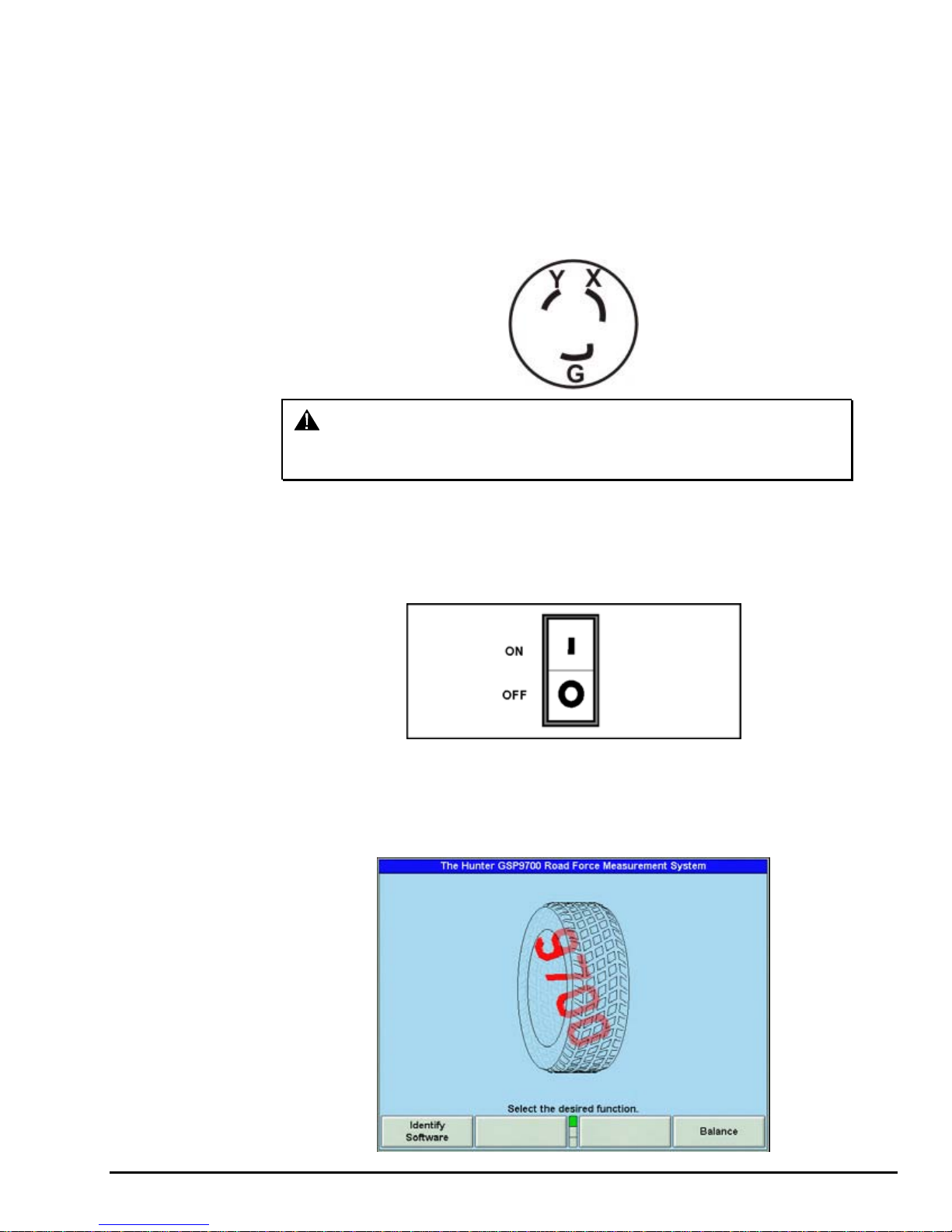
Turning Power ON/OFF
The ON/OFF switch is located on the back of the balancer cabinet. To turn the
balancer “ON,” press the “I” side of the ON/OFF switch. To turn the balancer “OFF,”
press the “O” side of the ON/OFF switch.
The system requires only a few seconds to “boot up.” During “boot up,” the system
will generate a high-pitched tone until the software is loaded and running.
After the GSP9700 performs a self-check, the “Logo” screen will appear indicating
the unit is ready for use.
GSP9700 Series Road Force Measurement System Operation 1. Getting Started 7
Page 16

Equipment Installation and Service
A factory-authorized representative should perform installation.
This equipment contains no user serviceable parts. All repairs must be referred to a
qualified Hunter Service Representative.
NOTE: To replace program cartridge, refer to “Program Cartridge
Removal and Installation,” page 103.
Equipment Specifications
Electrical
Voltage: 230 volts (208 - 240), 1 phase, 50/60 Hz
Amperage: 15 amperes
Wattage: 3450 watts (peak)
Air
Air Pressure Requirements: 100-175 PSI (6.9-12.0 bar)
Approximate Air Consumption: 4 CFM (110 Liters/Minute)
Atmospherics
Temperature:
+32F to +122F (0C to +50C)
Relative Humidity: Up to 95% Non-condensing
Altitude: Up to 6000 ft. (1829 m)
Sound Pressure Level
Equivalent continuous A-weighted sound pressure at operator’s
position does not exceed 70 dB (A).
Safety Summary
Explanation of Symbols
These symbols may appear on the equipment.
Alternating current.
Earth ground terminal.
Protective conductor terminal.
l ON (supply) condition.
OFF (supply) condition.
Risk of electrical shock.
Stand-by switch.
8 1. Getting Started GSP9700 Series Road Force Measurement System Operation
Not intended for connection to public telecommunications network.
Page 17
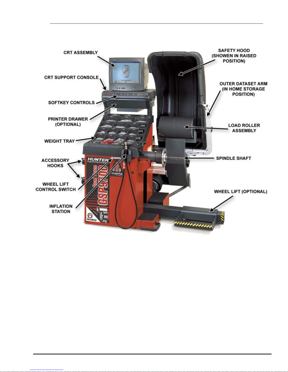
1.3 Equipment Components
GSP9700 Series Road Force Measurement System Operation 1. Getting Started 9
GSP9712
Page 18

Standard Balancer Accessories
A. 106-82-2 Sleeve, Scratch Guard for Small Cup
B. 175-353-1 Polymer Cup (4.5” O.D.)
C. 76-371-3 Quick Take-Up Wing Nut with Handles
D. 221-658-2 Hammer Heads (4)
E. 46-320-2 Spacer
F. 221-589-2 Weight Hammer/Pliers
G. 20-1650-1 Rim Tags
H. 221-659-2 Adhesive Weight Scraper
I. 223-68-1 Pressure Ring
J. 65-72-2 Calibration Weight
NOTE: Hunter wheel balancers do not include a standardized set of
mounting adaptors.
For optional accessories, refer to Wheel Balancer Brochure, Form 3203T.
10 1. Getting Started GSP9700 Series Road Force Measurement System Operation
Page 19

1.4 Operating the Console
Using Softkeys
The “softkeys,” located on the CRT support console directly beneath the CRT,
provide operator control of the balancer. The keys are identified as:
K1 key
K2 key
K3 key
K4 key
Menu shift key
Start key
Stop key
Reset key
The four menu labels that appear at the bottom of each video screen are referred to
as the “softkey labels.” Each label indicates the action that the program takes when
the corresponding K1, K2, K3, or K4 key is pressed.
The display between the “K2” and “K3” labels indicates how many rows of labels are
available. Most screens have only one or two rows, however more rows are possible.
The green box indicates the row that is currently displayed.
The menu row is changed by pressing the menu shift key,
. When this key is
pressed, the menu labels change to the next row down. If the last row is currently
displayed, the menu labels change to the first row.
Throughout this manual, the statement press “nnnnnnn” means press the softkey
with the label “nnnnnnn.” If the required label is not on the current menu, press
to
change rows until the desired label is displayed.
GSP9700 Series Road Force Measurement System Operation 1. Getting Started 11
Page 20

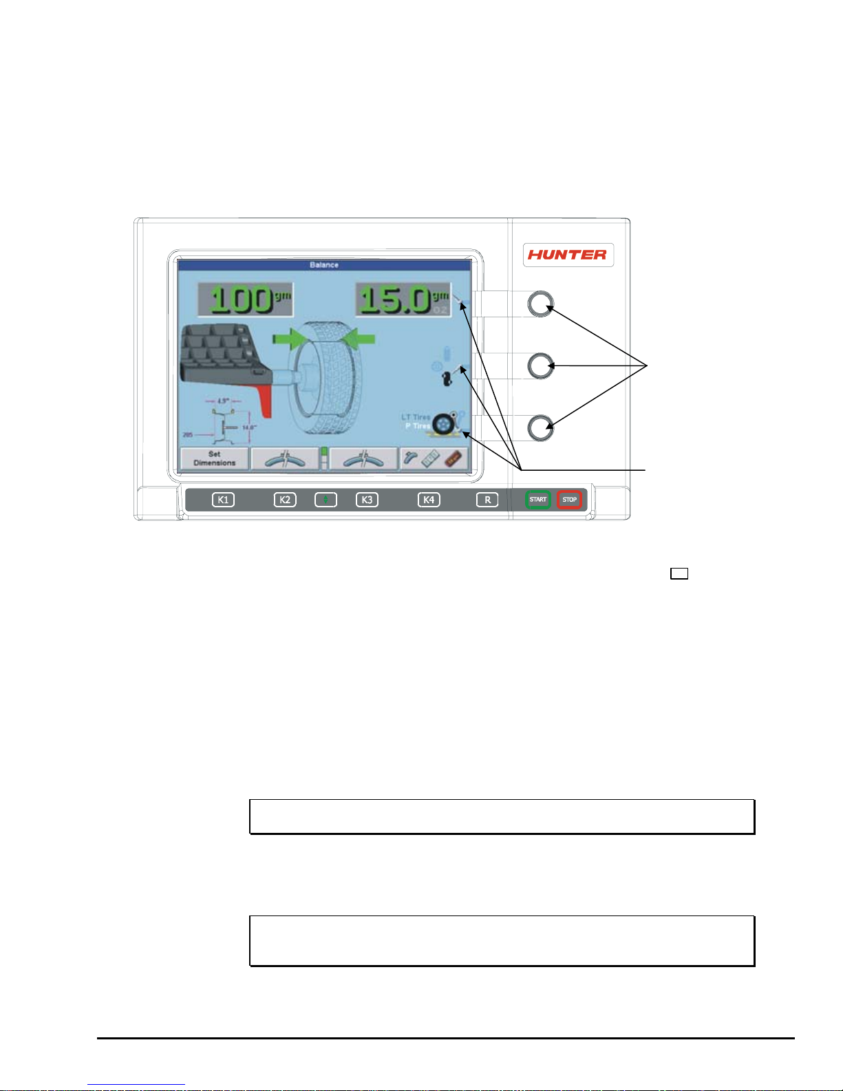
Primary Balancing Display
Using the Control Knob (GSP9712)
The control knob is located to the right of the softkeys. The control knob is used to
control the on-screen switches and manually input data. The on-screen switches that
are available are dependent upon the setup configuration of the balancer.
MENU
SHIFT
KEY
START
KEY
STOP
KEY
RESET
KEY
K1 KEY
K2 KEY
CONTROL KNOB ACCESSED ON-SCREEN SWITCHES
K3 KEY
K4 KEY
CONTROL
KNOB
Pushing in on the control knob cycles through the on-screen switches that are available
on the current primary screen. Rotating the control knob clockwise or counter-clo ckwise
changes the setting for the selected on-screen switch.
For example, in the “Balance” primary screen, pushing in on the control knob will cycle
through the grams to ounces, the static and dynamic, and the load roller on-screen
switches. After selecting an on-screen switch, the setting may be selected by rotating
the control knob. The “selected” switch is the one showing the hand.
12 1. Getting Started GSP9700 Series Road Force Measurement System Operation
Page 21
Using Control Knobs (GSP9702)
The control knobs are located to the right of the CRT screen. The control knobs are
used to control the on-screen switches and to manually input data. The control knobs
are identified as the upper, middle, and lower control knobs. The on-screen switches
that are available are dependent upon the current mode of the balancer.
For example, in the “Balance” primary screen, the upper knob (1) controls the grams
to ounces on-screen switch. The middle knob (2) controls the static, dynamic and
non-rounding on-screen switch, and the lower knob (3) controls the load roller and
P/LT tires on-screen switch.
1
2
3
Resetting the Program
The wheel balancing program may be reset at anytime by using the “ R ” key,
located on the CRT support console directly beneath the CRT. To reset the balancer,
press the reset key twice within a four-second period without pressing any other keys
in-between. This prevents a single accidental keystroke from resetting the system.
When the balancer is reset, the information collected for the wheel balance in
progress is erased and the display returns to the “Logo” screen.
Using the Screen Saver/Merchandising Display
If the CRT displays the same image for a long time, the image may become “burned
in” and will be visible even when the display is turned “OFF.” This is a characteristic
of all computer CRT displays. Therefore, after the designated time has passed, the
screen saver will appear on the CRT if “Screen Saver” is not disabled.
CONTROL KNOBS
ON-SCREEN
SWITCHES
NOTE: The system is still running when the screen saver is enabled.
When any “softkey” is pressed or the spindle turned, the program will reappear on the
CRT. This keystroke or spindle movement is recognized only by the screen saver
program and will not affect the balancer program. After the screen is on, additional
key presses will operate the program normally.
NOTE: The screen saver is not affected by rotating the control
GSP9700 Series Road Force Measurement System Operation 1. Getting Started 13
knob(s).
Page 22

14 1. Getting Started GSP9700 Series Road Force Measurement System Operation
Page 23

2. Balancing Overview
2.1 Balancing Modes
SmartWeight™ Balancing Technology
SmartWeight™ balancing technology is a method of reducing forces on a wheel
during balancing. This results in less weight used, and less time balancing tires.
SmartWeight is not a procedure. Instead, it measures the forces of side-to-side
shimmy and up-and-down shake and computes weight to reduce these forces. This
reduces the amount of weight, reduces time, reduces chec k spins and chasing
weights, and saves the shop time and money.
SmartWeight can reduce the number of steps in the balancing process.
Balancing Theory
Static Imbalance
As the word static implies, the tire will be balanced when at rest. For example, if an
unmoving assembly was centered on a cone and was balanced, it would be statically
balanced. A “bubble balancer” is designed to statically balance a tire/wheel
assembly.
IMBALANCE
FORCE
STATIC IMBALANCE
Static imbalance is where there is one amount of weight located in the center of the
tire/wheel assembly causing an imbalance. As the weight rotates, centrifugal forces
are created causing the wheel to lift as the weight reaches top dead center. This
lifting motion causes the tire/wheel assembly to move “up and down” creating a
bounce to be felt. This static imbalance condition is evident by a “jiggle” or up-down
movement of the steering wheel. These vibrations may also be apparent in the body,
with or without steering wheel shake.
FRONT VIEW
CUPPING
A statically imbalanced tire driven for an extended period may cause “cupping” in the
tire’s tread, create vibration, and adversely effect handling.
GSP9700 Series Road Force Measurement System Operation 2. Balancing Overview 15
Page 24

Static balancing alone is a seldom-recommended procedure. For example, a single
weight is commonly placed on the inner clip weight position for cosmetic purposes.
This is not a recommended practice and usually insures the assembly is not properly
dynamically balanced. The assembly may then experience side-to-side imbalance
while in motion, causing a shimmy condition and objectionable vibration.
Couple Imbalance
In general terms, dynamic imbalance is defined as where one or more locations of
the tire/wheel assembly are heavier causing an imbalance force and/or an imbalance
wobble. Shown below is a tire/wheel assembly with two heavy spots of equal weight
which are located 180 degrees radially from each other on opposite sides. As this
assembly rotates, centrifugal forces cause a large imbalance wobble to be created,
but the imbalance force (as well as the static imbalance) will be zero. A wheel with
this condition will cause a wobble or shimmy to be felt in the steering wheel.
Excessive dynamic imbalance of this type creates a shimmy that transfers through
the suspension components to the occupants of the vehicle, especially at higher
speeds.
IMBALANCE WOBBLE
(LATERAL TWIST OR TORQUE)
ZERO STATIC IMBALANCE WITH LARGE
COUPLE IMBALANCE
FRONT VIEW
16 2. Balancing Overview GSP9700 Series Road Force Measurement System Operation
Page 25

Modern “dynamic” balancers spin the wheel in order to measure both the up and
down imbalance force and the wobble or shimmy related imbalance (side-to-side).
Dynamic balancers direct the operator to place correction weights on the inside and
outside correction locations of the rim so that both imbalance shake (static) and
imbalance wobble (couple) will be eliminated.
SmartWeight may also utilize a single weight placement to balance out shake and
shimmy forces.
Static and Dynamic Imbalance Sensitivity
As a general rule of thumb, to achieve the best balance on an average sized tire and
wheel (15x6) assembly.
Residual static imbalance should be less than 1/4 ounce.
Residual couple imbalance should be less than 3/4 ounce.
Residual couple imbalance is preferred over remaining static imbalance.
It takes much more residual couple imbalance to cause a vibration than the same
amount of static imbalance.
The larger the diameter used for weight placement, the smaller the amount of
correction weight is required.
The wider the distance between the two weight placement locations, the smaller the
amount of correction weight is required.
If static balance is the only option, always verify that the remaining couple residual
imbalance is within acceptable tolerance.
For detailed information on adjustment and setup of modes of wheel balancing
sensitivity see section 5.1 and section 6.4.
GSP9700 Series Road Force Measurement System Operation 2. Balancing Overview 17
Page 26

2.2 Identifying the Static Balance Weight Plane
In “STANDARD BALANCE” mode, using only a clip-on weight, the plane is input as
follows:
For static balancing, it is recommended that you place half of the correctional weight
value on each side of the tire to reduce residual dynamic imbalance.
In “MIXED WEIGHTS BALANCE” mode and “ADHESIVE WEIGHTS BALANCE”
mode, using an adhesive weight, the plane is input as follows:
DIAMETER
For static balancing, it is recommended that the adhesive weight be placed as close
to the center of the wheel as possible to reduce residual dynamic imbalance.
In “PATCH BALANCE” mode, using a patch weight, the plane is input as follows:
DIAMETER
For static balancing, it is recommended that the patch weight be placed as close to
the center of the tread as possible to reduce residual dynamic imbalance.
18 2. Balancing Overview GSP9700 Series Road Force Measurement System Operation
Page 27

2.3 Identifying the Dynamic Balance Weight Planes
The balancer must know the location of the two weight circle planes for placement of
correction weights on the wheel assembly.
Each plane is described by a distance from the balancer and a diameter.
MIXED WEIGHTSST ANDARD PATCHADHESIVE WEIGHTS
RIM LIP / RIM LIP RIM LIP / INNER RIM SURFACE
INNER RIM SURFAC E /
INNER RIM SURFAC E
INNER TIRE SURFACE /
INNER TIRE SURF ACE
In “STANDARD BALANCE” mode, using only clip-on weights, left and right planes
are input as follows:
In “MIXED WEIGHTS BALANCE” mode, using clip-on and adhesive weights, the left
and right planes are input as follows:
In “ADHESIVE WEIGHTS BALANCE” mode, left and right planes are input as
follows:
GSP9700 Series Road Force Measurement System Operation 2. Balancing Overview 19
Page 28

In “PATCH BALANCE” mode, using patch weights, left and right planes are input as
follows:
LEFT DISTANCE
DIAMETER
RIGHT DISTANCE
2.4 SmartWeight™ Dynamic Weight Planes
SmartWeight requires the operator to enter two weight planes. This balancing
method will automatically determine if one or both weight planes require a weight to
be added. This eliminates “blinded” static single plane balancing, which alone may
not be sufficient to solve vibration issues.
20 2. Balancing Overview GSP9700 Series Road Force Measurement System Operation
Page 29

3. Mounting Wheels on the Balancer
3.1 Mounting the Wheel Using Wheel Lift (Optional)
The Wheel Lift is an optional feature on the GSP9700 series balancer. For
instructions on mounting the tire/wheel assembly without the optional wheel lift, refer
to “Mounting the Wheel,” page 23.
Raising the Tire/Wheel Assembly
Press the lift control handle “down” until the trolley carriage is at its lowest level.
Slide the appropriate mounting cone onto the spindle.
UP
LIFT CONTROL
DOWN
HANDLE
With the trolley carriage extended all the way out to the right, roll the tire/wheel
assembly onto the trolley carriage.
TROLLEY
CARRIAGE
Raise the lift control handle “up” to move the lifting beam and trolley into a position
where the tire/wheel assembly can be installed onto the spindle.
GSP9700 Series Road Force Measurement System Operation 3. Mounting Wheels on the Balancer 21
Page 30

Slide the tire/wheel assembly onto the spindle and center on the mounting cone.
A
Verify that the tire/wheel assembly is centered vertically on the spindle. Refer to
“Mounting the Wheel,” page 23.
TIRE/WHEEL
SSEMBLY CENTERED
VERTICALLY ON
SPINDLE
SPINDLE
Install the clamping cup and wing nut on the spindle shaft against the wheel and
secure the entire assembly by firmly tightening the wing nut, while depressing the
foot pedal to hold the spindle in place.
With the tire/wheel assembly secured to the GSP9700, press the lift control handle
“down” until the trolley carriage is at its lowest level.
NOTE: The trolley carriage will also retract to its lowest level
Service the tire/wheel assembly as necessary. Refer to “Balancing a Wheel,” page 35
for specific operation instructions.
22 3. Mounting Wheels on the Balancer GSP9700 Series Road Force Measurement System Operation
automatically when the hood is closed.
Page 31

Lowering the Tire/Wheel Assembly
Raise the hood.
Lift the lift control handle “up” to move the lifting beam and trolley into position to
support the tire/wheel assembly.
Step on the Spindle-Lok
®
/foot pedal of the GSP9700, and then loosen the wing nut
that secures the clamping cup.
With the wheel lift supporting the tire/wheel assembly, steady the tire/wheel assembly
with your left hand, and remove the wing nut and clamping cup with your right hand.
Slide the tire/wheel assembly to the right, so that it clears the spindle shaft.
Press the lift control handle “down” until the trolley carriage is at its lowest level.
Roll the tire/wheel assembly off the carriage trolley.
3.2 Mounting the Wheel (Without Wheel Lift)
CAUTION: Use only cones and accessories that are specifically
designed for the GSP9700 Series Road Force Measurement
System.
Since today’s vehicle designs are more sensitive to road feel, it is critical to achieve
the best balance. Proper balance requires that the tire/wheel assembly be centered
on the balancer. Tire/wheel assemblies can be balanced to zero, even with the
tire/wheel assembly mounted off-center. The main objective of the balancer operator
is to center the wheel on the hub and shaft, using the best available method.
Mounting the wheel off-center creates incorrect measurements of imbalance and
runout conditions.
Remove any existing wheel weights, rocks, and debris from the tire tread, and clean
the center hole of the wheel. Inspect inside of wheel for excessive accumulation of
dirt and debris. Remove if necessary before balancing.
Accurate balancing depends on accurately centering the wheel. Choose the prop er
wheel mounting cone by placing it in the center hole of the wheel to be balanced.
Refer to “CenteringCheck
®
,” page 30.
NOTE: If the basic cone and adaptors do not fit the wheel, additional
centering adaptors will be necessary. A wheel that cannot
be properly centered, cannot be properly balanced. All
balancers require additional centering adaptors to properly
center certain types of wheels. For additonal information,
refer to Form 3203T for optional accessories.
With the safety hood open, place the wheel mounting cone on the spindle shaft
against the captivated spring. Position the wheel with the inside surface facing the
balancer, centered on the cone.
Install the plastic clamping cup and wing nut on the spindle shaft against the wheel
and secure the entire assembly by firmly tightening the wing nut.
If equipped with optional Spindle-Lok
tightening the wing nut. Holding the shaft locked while tightening the wing nut
improves centering accuracy.
Slowly roll the wheel towards you while tightening the wing nut. This improves
accurate wheel centering, since the wheel is allowed to roll up the taper of the cone
as opposed to forcing it to slide up the cone.
GSP9700 Series Road Force Measurement System Operation 3. Mounting Wheels on the Balancer 23
®
foot pedal, depress and hold down while
Page 32

Mounting Error Detection Features
To verify that the tire/wheel assembly is centering, remount the tire/wheel assembly
and observe the results. Do any of the following conditions occur?
Weight amount varies excessively
Weight location changes
Runout and road force measurements vary excessively
If any of these conditions occur, the centering accuracy of the tire/wheel assembly
needs to be verified.
There are two methods using wheel runout that the GSP9700 will utilize to detect
mounting error:
Anytime the wheel runout is measured, the displayed diagnostic
message may caution the operator to check wheel mounting if
runout on inner and outer bead seats move up and down or side
to side together.
From the balance screen, the operator can choose to perform a
CenteringCheck
®
. The CenteringCheck® feature will automatically
confirm if the wheel is centered for the operator on the balancer
(preventing improper measurement from occurring).
See page 30, CenteringCheck
Front/Back Cone Mounting
®
, for a detailed description of the feature.
Cone mounting is one of the most common and reliable ways to mount wheels on
balancers. Select the proper wheel mounting cone by placing it in the center bore of
the wheel to be balanced. Select the cone that contacts the wheel nearest the center
of the cone.
Place the wheel mounting cone on the spindle against the spring plate. Mount the
wheel with the inner rim facing the balancer and centered on the cone.
Install the clamping cup and wing nut on the spindle shaft against the wheel and
secure the entire assembly by firmly tightening the wing nut, while depressing the
foot pedal to hold the spindle in place.
24 3. Mounting Wheels on the Balancer GSP9700 Series Road Force Measurement System Operation
Page 33

NOTE: If equipped with optional Spindle-Lok® foot pedal, depress
and hold down while tightening the wing nut. Holding the
shaft locked while tightening the wing nut improves centering
accuracy.
Slowly roll the wheel toward you during the initial tightening
of the wing nut. This aids in accurate wheel centering and
increased repeatability, since the wheel is allowed to roll up
the taper of the cone as opposed to forcing it to slide up the
cone.
WHEEL
MOUNTING
CONE
CAPTIVATED
SPRING
SURFACE
INSIDE
STANDARD
WHEEL
SPINDLE
SHAFT
WING NUT
PLASTIC
CLAMPING
CUP
Wheels with center holes over 3 9/16 inch diameter require the light truck cone. The
light truck cone can be installed from the outside of the wheel. (When using the light
truck cone, the plastic clamping cup is not used.)
LIGHT TRUCK
WHEEL
LIGHT
TRUCK CONE
GSP9700 Series Road Force Measurement System Operation 3. Mounting Wheels on the Balancer 25
CAPTIVATED
SPRING
PLASTIC
CLAMPING
CUP
NOT USED
Page 34

Using Plastic Wheel Mounting Washer
The plastic wheel mounting washer, 46-320-2, is used to prevent scratches on
wheels where the standard plastic cup and scratch guard cannot be used. The plastic
wheel mounting washer can also be used when mounting a wheel with a large offset
that is between cone sizes. Use of the washer as shown below can improve
centering ability by increasing cone pressure against the wheel.
For example: One cone size is too small because the captivated spring is not
pressing the cone against the inner wheel opening, but the next larger cone size is
too big and will not fit the opening. Use the smaller cone size with the plastic wheel
mounting washer to “extend” the captivated spring to hold the mounting cone against
the wheel opening with greater pressure.
PLASTIC
WASHER
LARGE OFFSET
MOUNTING
CONE
WHEEL
SPINDLE
SHAFT
CAPTIVATED
SPRING
WING NUT
PLASTIC
CUP
The scratch guard may be installed on the clamping cup to protect aluminum rims
from being marred, but should not be used on steel wheels.
NOTE: Use only the wing nut supplied with the GSP9700.
In some cases, the mounting pad of the wheel may be extremely wide, and the
standard clamp cup will not properly contact the wheel hub area. In these cases, the
optional nine-inch alloy wheel pressure cup may be used in place of the clamping cup.
26 3. Mounting Wheels on the Balancer GSP9700 Series Road Force Measurement System Operation
Page 35

Wheels with center bores over 3 9/16 inch diameter require one of the light truck
cones. The light truck cones must be mounted from the outside of the wheel.
NOTE: When using the light truck cones, the pressure ring is used
in place of the clamping cup.
This procedure utilizes a tapered cone inserted from the front side of the wheel
instead of the backside as previously described.
Select the proper wheel mounting cone by placing it in the center bore of the wheel to
be balanced. Choose the cone that contacts the wheel nearest the center of the
cone.
Mount the wheel with the inner rim facing the balancer. Place the wheel mounting
cone on the spindle with the small end of the cone facing the front of the wheel.
Install the wing nut and pressure ring assembly onto the spindle shaft against the
wheel and secure the entire assembly by firmly tightening the wing nut.
Heavy wheel centering may benefit by (1) pulling the tire away from the hub face at
top dead center while tightening the wing nut or (2) use of optional wheel lift to
position heavy wheel onto shaft and cone. This helps the wheel to overcome gravity
against the hub or spacer.
Cone/Flange Plate Mounting
Wheels may be centered using the lugholes and center bore with a flange plate and
centering cone. It is important that a back mounted cone be used to support and
center the wheel when using flange plates.
GSP9700 Series Road Force Measurement System Operation 3. Mounting Wheels on the Balancer 27
Page 36

The correct flange adaptor setup is determined by:
Measure and set the bolt circle diameter and number of studs to use
against the lug holes.
Set the number of lugholes as follows:
A three-lug wheel uses three studs.
A four-lug wheel uses four studs.
A five-lug wheel uses five studs.
A six-lug wheel uses three studs.
A seven-lug wheel uses seven studs.
An eight-lug wheel uses four studs.
Choose the correct taper design of flange studs to fit the wheel lug seats.
The mounting area of the flange stud must match the design of the
wheel’s lughole seat or depression.
The flange plate must be able to apply pressure to the center of the wheel while
maintaining perpendicularity to the shaft.
NOTE: If the lug seats are unevenly machined or worn, an optional
universal flange adaptor with compressible studs or bolt on
lugs may be used to more accurately mount the wheel with
the cone.
Flange plates are useful when the wheel cannot be properly centered off the hub
bore with a tapered cone alone because of improper fit, interference, or lack of a
center hole.
A flange plate in many cases adds value because it aids in more effective centering
than a tapered cone alone. This statement is true for many wheels including hub
centric wheels. That is why a flange plate and back cone may be more accurate and
repeatable, regardless of whether the wheel is lug centric or hub centric.
Expandable Collet Mounting
An expandable collet should NOT be used with the GSP9700 due to the amount of
force applied by the load roller.
Using the Pressure Ring and Spacers
Pressure Ring
The pressure ring clips on to the wing nut. It is used in lieu of the clamping cup.
It may also be used in place of a clamping cup if space is limited between the wheel
and the end of the spindle.
28 3. Mounting Wheels on the Balancer GSP9700 Series Road Force Measurement System Operation
Page 37

The pressure ring should be used to prevent the wing nut from directly contacting an
adaptor or a cone. It will act as a bearing to enable higher clamping forces.
Spacers
Hub Ring Spacers
These light truck spacers are designed to build a larger pocket when using extra
large truck cones. It also provides a location for the centering pins found on some
dual wheel configurations.
Shaft Spacers
The shaft spacer can be used to make the cone contact the hub bore more firmly.
For example, one cone size is too small because the captivated spring is not
pressing the cone against the inner wheel opening, but the next larger cone size is
too large and will not fit the opening. Use the smaller cone size, with the spacer, to
extend the captivated spring and hold the smaller mounting cone against the wheel
opening with greater pressure.
GSP9700 Series Road Force Measurement System Operation 3. Mounting Wheels on the Balancer 29
Page 38

CenteringCheck®
The CenteringCheck® feature can be used to inspect each mounting to identify
possible centering errors, thus preventing improper measurements from occurring.
The inner Dataset
mounting repeatability.
CenteringCheck
On-screen prompts lead you through the procedure as follows:
Select “Perform Centering Check” from the menu.
®
arm, is used to measure wheel runout which is an indication of
®
may be used with either a “bare rim” or a “rim with tire assembly.”
Place the inner Dataset® arm against the rim at a location that will maintain
unobstructed contact for a complete revolution. Refer to “Using the Auto Dataset
Arms,” page 48.
Press the outer Dataset® arm button or “Start” when ready to take readings.
30 3. Mounting Wheels on the Balancer GSP9700 Series Road Force Measurement System Operation
Page 39

Position the valve stem at 12 o’clock, and then press “Enter Valve Stem.”
After measuring rim runout, you will be prompted to loosen the wheel and re-clamp at
one half turn (approximately 180 degrees) from the current position.
Place the inner arm against the rim as shown.
Press the outer arm button or “Start” when ready to take readings.
Once more, position the valve stem at 12 o’clock, and then press “Enter Valve Stem.”
If the rim is centered properly, the following screen will appear briefly.
GSP9700 Series Road Force Measurement System Operation 3. Mounting Wheels on the Balancer 31
Page 40

The GSP9700 will then proceed to the “Balance” screen.
If a centering problem is detected, the following screen will appear.
The procedure will repeat the re-centering check up to four times and always
compare the previous measurement to the next check. If centering is not achieved
after four attempts, the following screen will appear.
Check for:
Correct mounting cone/adaptor for this wheel design.
Wheel defect such as a metal burr interfering with the
Dirt or debris interfering with the cone/adaptor.
Follow the on-screen prompts, and then press “Restart Procedure.”
32 3. Mounting Wheels on the Balancer GSP9700 Series Road Force Measurement System Operation
cone/adaptor.
Page 41

3.3 On-Vehicle Wheel Mounting Methods
Hub Centric
A hub centric wheel is aligned to the hub by the center bore of the wheel. The vehicle
weight rests on the hub bore. The clearance between the hub bore and the hub on a
hub centric wheel is between 0.003 and 0.004 of an inch. A hub centric wheel is
identified by removing the lug nuts (or bolts) and moving the wheel up, down, and
side-to-side. If there is little or no movement, the wheel is centered by the hub.
To verify if the wheel is hub centric:
Lug Centric
A lug centric wheel is identified by removing the lug nuts (or bolts) and moving the
wheel up, down, and side-to-side. If movement around the hub is apparent, the wheel
is centered on the vehicle by the lugs or studs of the axle flange.
Remove the lug nuts (or bolts) and try to move the wheel up/down and
side/side on the hub.
If the wheel has no appreciable movement around or about the
centerline of the hub, it should be considered hub centric.
A hub centric wheel will have very little (0.003 – 0.004”) clearance or a
slip fit to the hub.
GSP9700 Series Road Force Measurement System Operation 3. Mounting Wheels on the Balancer 33
Page 42

To verify if the wheel is lug centric:
Remove the lug nuts (or bolts) and try to move the wheel up/down and
side/side on the hub.
A lug centric wheel will display noticeable movement.
TIP: When mounting a lug centric wheel to a vehicle, extreme
centering care must be taken by ensuring the lug nuts (bolts)
are tightened equally, while rotating the wheel.
“Step-torque” star pattern to proper torque specification.
34 3. Mounting Wheels on the Balancer GSP9700 Series Road Force Measurement System Operation
Page 43

4. Balancing a Wheel
4.1 Balancing Procedures
The GSP series balancer offers two primary ways to balance tires:
1. SmartWeight™ balancing technology
2. Traditional balancing technology
Both of these methods can balance tires dynamically. The main difference is
SmartWeight will reduce the amount of corrective weight and possibly limit the
number of steps in a basic wheel balancing situation.
SmartWeight™ Balancing Technology
SmartWeight™ balancing technology is a method of reducing forces on a wheel
during balancing. SmartWeight is not a procedure. Instead, it measures the forces of
side-to-side movement and up-and-down shake and computes weight to redu ce
these forces. This reduces the amount of weight, reduces time, reduces check spins
and chasing weights. SmartWeight saves the shop time and money.
Using SmartWeight™
The SmartWeight enabled balancing display varies slightly from the standard
balancing display. The primary difference between the displays is the SmartWeight
tire graphs that display the static and couple forces within a tire/wheel assembly.
The red-dotted line represents the acceptable amount of force the tire can have that
will not result in a ride problem. Any forces below that line will be shown in green.
Any forces that are above that level will be shown in red and indicate an excessive
amount of force.
The traditional “static” and “dynamic” modes are eliminated. The traditional non-round
off mode is eliminated. These modes are no longer necessary with SmartWeight
balancing.
GSP9700 Series Road Force Measurement System Operation 4. Balancing a Wheel 35
Page 44

Install the tire/wheel assembly as normal. Rim measurements are not required.
Lower the hood and spin.
If SmartWeight requires correction weights wheel dimensions will be required.
Enter the dimensions using the dataset arms. The SmartWeight tire graphs will
display red for excessive forces and green for acceptable amounts of force. Prior to
measurement the tire graphs will display no color.
The screen will display the amount and location of corrective weight necessary.
Install the weights in the appropriate manner using the correct type of weight and
lower the hood to re-spin and check the balance.
Instead of displaying zeros in the weight display, SmartWeight displays “OK,”
indicating that the force levels are reduced to within the acceptable tolerances.
36 4. Balancing a Wheel GSP9700 Series Road Force Measurement System Operation
Page 45

Switching from SmartWeight™ to Traditional Dynamic Balancing Modes
At any time, SmartWeight can be switched to standard balancing as long as both
standard and SmartWeight modes are enabled in setup.
On units with a control knob, press the knob until SmartWeight is highlighted. Once
highlighted, press and hold the knob till the standard balance icons appear. Cycle
back the same way.
On units without the control knob select the “Disable SmartWeight” button on the
balance screen.
Dynamic Balancing Selection
Dynamic balancing is selected by pointing the indicator to while rotating the
control knob. Dynamic will always display two weight planes.
Dynamic balancing provides a more complete balance than static balancing.
Dynamic balancing should be selected whenever possible to minimize vehicle
vibration. Refer to “Dynamic Imbalance,” page 16.
Static Balancing Selection
Static balancing is selected by pointing the indicator to while using the control
knob. Static balancing provides a less desirable balance than dynamic bala ncing.
Dynamic balancing should be selected whenever possible to minimize vehicle
vibration. Refer to “Static Balance,” page 15.
GSP9700 Series Road Force Measurement System Operation 4. Balancing a Wheel 37
Page 46

Static Balance Mode Reminder for “Dynamic Balance Importance”
(Except Patch Balance)
Two reminder pop-up text messages appear on the balance screen dialog box when
you first select static mode.
The first screen gives the warning: Avoid STATIC single-plane balancing.
The second screen suggests: DYNAMIC dual-plane balancing recommended (even
for hidden weights).
If STATIC is selected, the reminders show up again at the end of the spin, and if in
clip-on weight mode, the dynamic weights are shown momentarily, and then the
static weight is displayed.
38 4. Balancing a Wheel GSP9700 Series Road Force Measurement System Operation
Page 47

A
Selecting Weight Types and Placement Modes
Press “ ” to change the weight types and placement. The GSP970 0 offers
Standard Balance, Mixed Weights Balance, Adhesive Weights Balance, and Patch
Balance
for dynamic and static modes.
With these four selections, a correction weight can be placed at an infinite number of
locations, based upon the choice of the operator.
DYNAMIC
STATIC
STANDARD
BALANCE
MIXED
WEIGHTS
BALANCE
PATCH
BALANCE
DHESIVE
WEIGHTS
BALANCE
STANDARD BALANCE should be selected when clip-on weights can be used for
both rim flanges.
MIXED WEIGHTS BALANCE should be selected when a clip-on weight can be used
on the inner rim flange, but not on the outer rim flange. Mixed Weights Balance uses
an adhesive weight for the right weight plane instead of a clip-on weight to avoid
marring aluminum rims or to hide weights from view.
ADHESIVE WEIGHTS BALANCE should be selected when clip-on weights cannot be
used on either rim flange.
PATCH BALANCE should be selected when the tire has a very large imbalance in
the tire assembly. The large imbalance can be corrected with Patch Balancing and
then the assembly can be fine-tuned with one of the other balancing procedures.
STANDARD Balancing Procedure (Using Clip-On Weights)
Verify that the wheel is clean and free of debris.
Remove all previous weights.
Mount tire/wheel assembly. Refer to “Mounting the Wheel,” page 23.
Press “
Use the softkey arrows to select “STANDARD BALANCE” and press “OK.”
GSP9700 Series Road Force Measurement System Operation 4. Balancing a Wheel 39
.”
Page 48

Select either grams or ounces by rotating the control knob and highlighting either “g”
or “oz.”
Select “DYNAMIC” by rotating the control knob to highlight “
.” Refer to “Dynamic
Balancing Selection,” page 37.
Use both Dataset
measure the distance, diameter, and rim width dimensions. Refer to “Using the Auto
Dataset
®
Arms,” page 48.
NOTE: The Dataset
®
arms in the UPWARD position at the clip-on weight location to
®
Arms should be positioned in the location for
weight placement. Refer to “Measuring Dimensions for
Standard Clip-on Weight Balancing,” page 49.
Enter the data by depressing the foot pedal. Release the Dataset® arms.
Close safety hood.
Press the green “START” button if “Hood Autostart” is disabled.
After wheel comes to a complete stop, raise the safety hood.
The GSP9700 will find the TDC for the left weight plane if “Servo-Stop” is enabled.
“Servo-Stop” will hold the wheel in the TDC position while the weight is applied. The
weight amount will be displayed in green.
Attach the weight amount shown on the CRT for the left weight plane to the inner rim
of the wheel.
If necessary, use the left “ ” to split the weight. Refer to “Split Weight®
Feature,” page 87.
Press the green “START” button with the safety hood in the raised position and the
GSP9700 will find the TDC for the right weight plane.
40 4. Balancing a Wheel GSP9700 Series Road Force Measurement System Operation
Page 49

Attach the weight amount shown on the CRT for the right weight plane to the outer
rim of the wheel.
If necessary, use the right “ ” to split the weight. Refer to “Split Weight®
Feature,” page 87.
Verify balance condition by spinning again with the load roller disabled. Refer to
“Load Roller Operation,” page 60.
Left and right weight plane displays should show “zero.”
STANDARD balancing procedure is complete.
MIXED WEIGHTS Balancing Procedure
(Combination of Clip-On & Adhesive Weights)
Verify that the wheel is clean and free of debris.
Remove all previous weights.
Mount tire/wheel assembly. Refer to “Mounting the Wheel,” page 23.
Press “
Use the arrows to select “MIXED WEIGHTS BALANCE” and press “OK.”
Select either grams or ounces by rotating the control knob and highlighting either “g”
or “oz.”
.”
Select “DYNAMIC” by rotating the control knob to highlight “
Balancing Selection,” page 37.
GSP9700 Series Road Force Measurement System Operation 4. Balancing a Wheel 41
.” Refer to “Dynamic
Page 50

Use both Dataset® arms in the UPWARD position at the clip-on weight location to
measure the distance, diameter, and rim width dimensions. Refer to “Using the Auto
Dataset
®
Arms,” page 48.
Do NOT return the arm to the “home” position.
Using the DOWNWARD position, move the inner Dataset
®
arm disk edge to the
location for placement of the right edge of the adhesive weight on the right weight
plane and enter data by depressing the foot pedal. Refer to “Using the Auto Dataset
Arms,” page 48.
Close safety hood.
Press the green “START” button if “Hood Autostart” is disabled.
After wheel comes to a complete stop, raise safety hood.
The GSP9700 will find the TDC for the left weight plane if “Servo-Stop” is enabled.
“Servo-Stop” will hold the wheel in the TDC position while the weight is applied.
Attach the clip-on weight amount shown on the CRT for the left weight plane to the
inner rim of the wheel.
®
If necessary, use the left “ ” to split the weight. Refer to “Split Weight®
Feature,” page 87.
42 4. Balancing a Wheel GSP9700 Series Road Force Measurement System Operation
Page 51

With the servo enabled, attach the adhesive weight using the weight amount shown
for the right weight plane on the CRT. Refer to “Servo-Aided Adhesive Weight
Placement,” page 51. If servo is not enabled, BDC placement should be used. Refer
to “Manual Weight Position Measurement,” page 48.
BDC
SERVO - AIDED
ARM CONTACT POINT
If necessary, use the right “ ” to split the weight. Refer to “Split Weight®
Feature,” page 87.
Verify balance condition by spinning again with the load roller disabled. Refer to
“Load Roller Operation,” page 60.
Left and right weight plane displays should show “zero.”
MIXED WEIGHTS balancing procedure is complete.
ADHESIVE WEIGHTS Balancing Procedure (Adhesive Weights Only)
Verify that the wheel is clean and free of debris.
Remove all previous weights.
Mount tire/wheel assembly. Refer to “Mount the Wheel on the Spindle Shaft,” page
23.
Press “
Use the arrows to select “ADHESIVE WEIGHTS BALANCE” and press “OK.”
Select either grams or ounces by rotating the control knob and highlighting either “g”
or “oz.”
Select “DYNAMIC” by rotating the control knob to highlight “
Balancing Selection,” page 37.
GSP9700 Series Road Force Measurement System Operation 4. Balancing a Wheel 43
.”
.” Refer to “Dynamic
Page 52

Using the DOWNWARD position, place the inner Dataset® arm disk edge to the
outermost location for placement of the right edge of the left adhesive weight and
enter the data by depressing the foot pedal. Refer to “Using the Auto Dataset
®
Arms,”
page 48.
Do NOT return the inner Dataset® arm to the “home” position.
Using the DOWNWARD position, move the inner Dataset
innermost location for placement of the right edge of the right adhesive weight and
enter the data by depressing the foot pedal. Refer to “Using the Auto Dataset
®
arm disk edge to the
®
Arms,”
page 48.
Close safety hood.
Press the green “START” button if “Hood Autostart” is disabled.
After wheel comes to a complete stop, raise the safety hood.
With the servo enabled, attach the adhesive weight for the left weight plane using the
weight amount shown on the CRT. Refer to “Servo-Aided Adhesive Weight
Placement,” page 51. If servo is not enabled, BDC placement should be u sed. Refer
to “Manual Weight Position Measurement,” page 48.
If necessary, use the left “ ” to split the weight. Refer to “Split Weight®
Feature,” page 87.
Return the inner Dataset
44 4. Balancing a Wheel GSP9700 Series Road Force Measurement System Operation
BDC
®
arm to the home position.
SERVO-AIDED
ARM CONTACT POINT
Page 53

T
With the servo enabled, attach the adhesive weight for the right weight plane using
the weight amount shown on the CRT. Refer to “Servo-Aided Adhesive Weight
Placement,” page 51. If servo is not enabled, BDC placement should be used. Refer
to “Manual Weight Position Measurement,” page 48.
BDC
SERVO-AIDED
ARM CONTACT POIN
If necessary, use the right “ ” to split the weight. Refer to “Split Weight®
Feature,” page 87.
Verify balance condition by spinning again with the load roller disabled. Refer to
“Load Roller Operation,” page 60.
Left and right weight plane displays should show “zero.”
ADHESIVE WEIGHTS balancing procedure is complete.
PATCH BALANCE® Procedure
Weighted balance patches will be placed on the inside of the tire at the edge of the
tread area beside the sidewall as shown below:
LEFT PLANE
INTERNAL DIAMETER
NOTE: Weighted balance patches should be installed only in tread
GSP9700 Series Road Force Measurement System Operation 4. Balancing a Wheel 45
RIGHT PLANE
area. Do not install weighted balance patches near sidewall
or shoulder of tire.
Page 54

Verify that the wheel is clean and free of debris.
Remove all previous weights.
Mount tire/wheel assembly. Refer to “Mounting the Wheel,” page 23.
Press “
.”
Use the arrows to select “PATCH BALANCE” and press “OK.”
Select either grams or ounces by rotating the control knob and highlighting either “g”
or “oz.”
Select “DYNAMIC” by rotating the control knob to highlight “
.” Refer to “Dynamic
Balancing Selection,” page 37.
NOTE: When measuring large tires that will use balance patches, it
may require removal of the outer arm “home position”
bumper for ample clearance of the outer Dataset® arm. The
bumper can be removed by loosening three Phillips head
screws and gently pulling the bumper away from the arm.
PHILLIPS HEAD
BUMPER
PHILLIPS HEAD
SCREW
SCREW
PHILLIPS HEAD
SCREW
Measure and enter the weight plane distances as follows:
Set two of the widest weighted balance patches available side-by-side on
the tread directly above where the left and right weighted patches will be
installed inside of the tire. The patches should be positioned as far apart
from each other as possible, but should not be placed in the sidewall or
shoulder area of the tire.
Mark the tire tread at the center of the patches for future placement
reference and remove the patches from the wheel.
Place outer Dataset
®
arm roller directly over the left mark and enter data
by depressing the foot pedal.
46 4. Balancing a Wheel GSP9700 Series Road Force Measurement System Operation
Page 55

Place outer Dataset® arm roller directly over the right mark and enter
data by depressing the foot pedal.
Close safety hood.
Press the green “START” button if “Hood Autostart” is disabled.
After wheel stops spinning, raise the safety hood.
Press the green “START” button with the safety hood in the RAISED position and the
GSP9700 will find TDC for the left weight plane. Mark the tire’s inner sidewall for
patch placement.
Press the green “START” button with the safety hood in the RAISED position and the
GSP9700 will find TDC for the right weight plane. Mark the tire’s outer sidewall for
patch placement.
Place an aligning mark on the tire and rim to align them back together after applying
the patch weights.
Remove wheel from balancer and dismount tire from rim.
Install left weight plane weighted balance patch(s) at mark(s) as instructed by
manufacturer's instructions.
Install right weight plane weighted balance patch(s) at mark(s) as instructed by
manufacturer's instructions.
Mount tire onto rim, aligning rim and tire marks.
Verify balance condition by spinning again with the load roller disabled. Refer to
“Load Roller Operation,” page 60.
Finish the patch balancing procedure by returning to the appropriate balance
procedure for the type of wheel being balanced. Verify balance condition by spinning
again, and attach weights as necessary to correct for residual imbalance.
PATCH balancing procedure is complete.
GSP9700 Series Road Force Measurement System Operation 4. Balancing a Wheel 47
Page 56

4.2 Using the Auto Dataset® Arms
Auto Dataset® arms perform two functions:
1. Input weight position measurements for balancing.
2. Input wheel runout measurements for Road Force Measurements.
Refer to “Road Force Measurement,” page 133.
Auto Dataset
traditional methods. Auto Dataset
weight plane location automatically. The Dataset
positioned on the weight plane and data is entered by depressing the foot pedal.
Automatic Weight Position Measurement
The Dataset® arms can be used to enter weight position dimensions instantly and
accurately. The arms are “triggered” when they are moved away from their home
position. When the arms are triggered, a blinking graphic depicting the Dataset
on the “Dimension Entry” screen identifies the plane currently being inputted.
®
is a faster and more accurate method to take rim measurements than
®
INNER DATASET
ARM TRIGGERED
(BLINKING)
is used to input rim distance, rim width, and
®
Arms of the GSP9700 are
®
arm
In most cases, the Dataset® Arms are used to input the exact weight position.
The exact weight position is entered by holding the arm(s) stable in the desired
location and depressing the foot pedal to enter the dimensional data.
Manual Weight Position Measurement
While on the “Set Dimensions” view of the “Balance” primary screen, the control knob
can be used to enter rim dimensions manually.
48 4. Balancing a Wheel GSP9700 Series Road Force Measurement System Operation
Page 57

Measuring Dimensions for Standard Clip-on Weight Balancing
To measure rim dimensions for clip-on weights, activate the Standard balancing
mode. Pull the inner Dataset
touching the top of the wheel inner rim lip. Simultaneously pull the outer Dataset
arm out and upward until it is touching the top of the wheel outer rim lip. While the
Dataset
®
arms are in place, depress the foot pedal to enter the dimensional data. The
GSP9700 will beep to confirm data entry.
NOTE: Dataset
®
arm away from the weight tray and UPWARD until it is
®
arms can input dimensions separately if desired.
®
Measuring Dimensions for Mixed Weights (Clip-on/Tape-on) Balance
To measure rim dimensions for the clip-on weight, pull the inner Dataset® arm away
from the weight tray and UPWARD until it is touching the wheel inner rim lip. Depress
the foot pedal to enter the dimensional data. The GSP9700 will beep to confirm data
entry.
Do NOT return the Dataset® arm to the home position.
Move the Dataset
at the right edge of the desired adhesive weight location. Depress the foot pedal to
enter the dimensional data. The GSP9700 will beep to confirm data entry.
®
arm DOWNWARD until the roller disk edge is touching the wheel
GSP9700 Series Road Force Measurement System Operation 4. Balancing a Wheel 49
Page 58

Measuring Dimensions for Adhesive Weights Balancing
(Tape-on/Tape-on)
To enter adhesive weight dimensions for the inner plane, pull the inner Dataset® arm
away from the weight tray and DOWNWARD, until the roller disk edge is touching the
wheel at the right edge of the desired left weight plane location. Depress the foot
pedal to enter the dimensional data. The GSP9700 will beep to confirm data entry.
Do NOT return Dataset® arm to the home position.
Move the Dataset
position and depress foot pedal to enter dimensional data. The GSP9700 will beep to
confirm data entry.
®
arm at the right weight plane location in the DOWNWARD
50 4. Balancing a Wheel GSP9700 Series Road Force Measurement System Operation
Page 59

Measuring 20 Inch or Larger Rims
Adjustable Length Inner Dataset Arm
The inner dataset arm is an extendable two-position arm that can measure data entry
and runout for wheels up 30-inch diameter. Retracted arm position measures 10” to
21” wheels. Extended arm position measures 20” to 30” wheels.
Retracted or extended position of inner arm is chosen by the operator from the “Enter
Dimensions” screen. This will appear when the inner Auto Dataset arm is activated.
The extendable inner dataset arm also has the built in stick-on weight holder used to
grip adhesive weights for accurate placement on the wheel.
Enabling the dataset arm type to extendable requires that the Service Mode must be
accessed and enable in Set Up.
To extend and lock the arm, loosen the locking screw, and slide the arm to the
desired length.
If the GSP balancer is not equipped with the extendable two-position arm, an
upgrade kit is available through the local Hunter Engineering Company service
representative.
Servo-Aided Adhesive Weight Placement
When Servo-Stop is enabled in setup, the inner Dataset® arm can be used to assist
in proper placement of adhesive weights. Servo-aided weight placement is a more
precise method of weight placement than manual weight placement. The motor will
automatically rotate the wheel to the contact point of the arm. This eliminates the
need for you to “eyeball” BDC, which often results in weight placement error.
Spin the wheel using Mixed Weights or Adhesive Weights selection.
Shape the weight to a contour similar to the curve of the rim.
GSP9700 Series Road Force Measurement System Operation 4. Balancing a Wheel 51
Page 60

Place the required amount of adhesive weight in the weight clip on the inner Dataset®
arm and remove the peel-off backing from the adhesive weight.
NOTE: The adhesive weight strip should be centered in the weight
clip and the peel-off backing should face away from the inner
Dataset® arm.
Using dimensional information previously obtained, the on-screen graphic displays
and identifies the exact location of the weight plane and the current position of the
inner Dataset
®
arm. Pull the inner Dataset® arm out from the base until the arm and
the weight location are overlapping.
Maintaining that distance, rotate the Dataset
®
arm toward the inner rim surface, and
then apply the adhesive weights to the rim by pressing the adhesive weight release tab.
NOTE: If the servo is off (but is enabled in setup), pressing the
“START” button with the hood in the RAISED position will
restart the servo for adhesive weight application.
52 4. Balancing a Wheel GSP9700 Series Road Force Measurement System Operation
Page 61

Manual Adhesive Weight Placement
NOTE: Manual weight placement is not as accurate as servo-aided
weight placement. Servo-aided weight placement should be
used whenever possible.
NOTE: If the servo-aided weight placement is enabled, press the
“STOP” button with the hood in the RAISED position to
disable.
To manually place adhesive weights on the rim after spinning, the inner Dataset® arm
should be used to verify the previously inputted distance.
Rotate the wheel until the location arrow of the desired weight plane is green.
Lift the inner Dataset
between the two numbers that represent previously inputted data displays the current
reading of the inner Dataset
®
arm from home position. The “real-time” number displayed
®
arm. The arm should be placed in the downward
position on the rim until the real-time number matches the previously inputted data.
NOTE: Lifting the inner Dataset
®
arm will trigger the balancer for
dimension input. Do NOT step on the foot pedal or new
dimensions will be entered.
The weight should be placed at BDC at that distance.
“REAL-TIME”
NUMBER
GSP9700 Series Road Force Measurement System Operation 4. Balancing a Wheel 53
Page 62

Rim Runout Measurements
Rim runout can be measured externally with the tire mounted to the rim bead seats,
or the bare rim can be measured separately for more precise measurements. If the
assembly does not have a flat faced rim, take the runout measurement. Refer to “Rim
Runout External Measurement (Tire and Wheel Assembly),” below. If the assembly is
flat faced, and you are prompted by the GSP9700 to take runout data, or to verify the
runout data already taken with the tire in place, take the runout measurement as
described in “Rim Runout Measurement (Bare Rim),” page 56.
Bare rim measurement is a more accurate method of measuring rim runout. Bare rim
measurements can also be used to audit bare rims prior to the installation of a tire.
Runout can be viewed by selecting “Show Runout & Road Force” from the “Balance”
primary screen.
Single Arm Rim Runout External Measurement (Tire and Wheel Assembly)
The inner Dataset Arm can be used alone externally to measure rim runout of the
inboard bead seat. This method is not as accurate as two position measurement, but
it is faster for QuickMatch™ predictions.
Dual Arm Rim Runout External Measurement (Tire and Wheel Assembly)
If the GSP9700 determines that there is a problem with the wheel assembly, it will
prompt you to measure rim runout. The “Measure Rim Runout” popup screen can be
selected from the “Balance” primary screen, or by pressing the outer arm button
once. To measure rim runout with the tire on the rim, remove all clip-on weights from
the rim and place the inner and outer Dataset
®
arm on the rim as shown below:
NOTE: Note the location of the Dataset
location for rim runout measurement is NOT the same as the
location for inputting rim dimensions for weight location.
®
arms on the rim. The
54 4. Balancing a Wheel GSP9700 Series Road Force Measurement System Operation
Page 63

When Dataset® arms are in place, press the outer arm button. The motor will slowly
rotate the wheel to measure runout. While the wheel is in motion, gently apply
upward and inward fingertip pressure on both Dataset
®
arms as shown below:
CAUTION: Take care when placing hands to measure rim runout that
no part of your hands or body interfere with parts in motion.
NOTE: Do not grasp the Dataset® arms. Use fingertip pressure only.
OUTER ARM
BUTTON
The runout data will automatically be displayed when the operation is complete. The
inner and outer rim runout first harmonics will be shown as amounts in the upper lefthand corner of the screen. Radial high spots of runout will be shown as blue
indicators on the rim. Lateral high spots will be shown as orange indicators on the rim
when “Show Lateral High Spots” is selected. The average of the inner and outer
radial first harmonic high spots are taken to locate the average radial first harmonic
rim low spot (matching mark). Refer to “Harmonics & T.I.R. Data/Plots,” page 98.
GSP9700 Series Road Force Measurement System Operation 4. Balancing a Wheel 55
Page 64

Rim Runout Measurement (Bare Rim)
To measure bare rim runout, remove the tire from the rim. Mount the bare rim on the
GSP9700. Select “Measure Rim Runout” from the “Balance” primary screen. Select
“Measure Bare Rim.” Loosen the outer Dataset
counter-clockwise. Pull out and rotate the rim runout ball on the outer Dataset
to the downward position. Secure the locking screw. Place the outer Dataset
ball against the left bead seat lip as shown below:
®
arm locking screw by turning it
OUTER ARM
BUTTON
®
arm
®
arm
OUTER DATASET
ARM BALL
LOCKING
SCREW
When outer Dataset® arm ball is in place, press the outer arm button. The motor will
slowly rotate the rim to measure runout. While the wheel is in motion, gently apply a
downward and outward pressure on the outer Dataset
When the screen prompts, place the outer Dataset
®
arm ball.
®
arm ball against the right bead
seat lip as shown below:
When the Dataset® arm ball is in place, press the outer arm button. The motor will
slowly rotate the rim to measure runout. While the wheel is in motion, gently apply a
downward and outward pressure on the Dataset
If the data will be used in ForceMatching™, scribe a mark with chalk or a marker to
realign the rim to the hub/shaft assembly after the tire is mounted. After mounting the
tire and re-spinning, the runout data of the bare rim may be recalled by pressing
“Recall Last Rim Data” from the “Runout & Road Force” popup screen. Refer to
“ForceMatching™ Using Previous Bare Rim Measurement,” page 63.
56 4. Balancing a Wheel GSP9700 Series Road Force Measurement System Operation
®
arm ball.
Page 65

4.3 Primary and Popup Screens
Primary Screen Selection
Primary screens are selected from either of the two softkey rows of the “Logo” screen
of the GSP9700 by pressing the menu shift key.
When a primary screen is showing, there is only a single “title bar” across the top of
the display. For example, see the following “Balancer Set Up” primary screen.
Within each primary screen, there are popup screens that can be selected. A popup
screen pops up over the current screen to perform that operation, and the softkeys
change to those needed to support the operation.
GSP9700 Series Road Force Measurement System Operation 4. Balancing a Wheel 57
Page 66

For example, the “CenteringCheck®” popup screen pops up over the “Balance”
primary screen. The softkeys change from the primary screen to support the
“CenteringCheck®” operation.
When the operation is complete or has been cancelled/exited, the popup screen
reveals the primary screen from which it appeared.
Notice two very important aspects of this scheme:
The popup screen does not completely “hide” the screen over which it
pops up. It leaves the title bar of the primary screen exposed while the
title bar of the current selection is highlighted.
The popup screen has a softkey menu that supports only the operations
required by that screen. This greatly simplifies the menus of the primary
screens and makes it easier to control the operation of the popup
screens.
Balance Primary Screen
The “Balance” primary screen has a choice of two related views. They are:
Set Dimensions
Apply Weights
By pressing “Set Dimensions” or “Apply Weights,” the primary screen toggles views
of the current operation. The first row menu keys will change to those needed for the
current view, while the second and third row menu keys remain the same.
The “Apply Weights” view is the spinning operation view of the balancer. The Split
Weight
switches change the gram/ounce selection, the dynamic/static (blind/round) selection,
and the load roller enable/disable selection.
®
softkeys are available in this view on the first row menu. The on-screen
58 4. Balancing a Wheel GSP9700 Series Road Force Measurement System Operation
Page 67

The “Set Dimensions” view is displayed in reduced size in the lower left-hand corner.
It can be enlarged by pressing “Set Dimensions” or will automatically enlarge if a
Dataset
®
Arm is moved from home position and triggered to take rim data.
“BALANCE VIEW”
The “Set Dimensions” view enlarges the dimensional diagram of the wheel assembly.
The inch/millimeter selection softkeys are available in this view on the first row menu.
The control knob(s) can be used to manually enter the rim dimensions. The “Apply
Weights” view is displayed in reduced size in the lower left-hand corner. It can be
enlarged by pressing “Apply Weights,” or will automatically enlarge if the wheel is
spun or if both Dataset
®
arms are in the home position after one or both arms have
been triggered to take rim data.
“SET DIMENSIONS VIEW”
GSP9700 Series Road Force Measurement System Operation 4. Balancing a Wheel 59
Page 68

4.4 Load Roller
Load Roller Operation
The load roller runs parallel to the tire and applies a perpendicular load on the
assembly to take Road Force Measurements. It is capable of applying up to 1400
pounds of force. The amount of force placed on the tire is dependent upon the tire’s
diameter and stiffness. The load roller will not overload the tire.
NOTE: It is important that the air pressure of the tire is set to
The load roller can be enabled and disabled by turning the control knob. When the
load roller is enabled, the CRT will display the load roller on the screen as shown
below.
specifications prior to the Road Force Measurement.
Incorrect tire pressure will affect the results.
If the GSP9700 is equipped with the Inflation Station feature,
the tire can be easily set to the specified air pressure. Refer
to “Inflation Station,” page 81.
QUICKMATCH WITH LIMITS ENABLED
Road Force with Limits Enabled: when the load roller selection is made, “LT Tires,”
“P-SUV Tires,” or “P Tires” road force specifications can be highlighted by slowly
turning the knob to the appropriate selection. Changing the “LT Tires,” “P-SUV Tires,”
or “P Tires” selection will change the limit specifications for road force and rim runout.
Refer to “Setting Up the Runout & Road Force Units,” page 109.
NOTE: The load roller cannot be enabled in “Bare Rim Spin” mode.
When the load roller is disabled, only a balance spin will be performed. This can be
useful for a balance check spin after weights have been applied.
Load roller data can be viewed by selecting “Show Runout & Road Force” from the
“Balance” primary screen.
60 4. Balancing a Wheel GSP9700 Series Road Force Measurement System Operation
Page 69

4.5 ForceMatching™
ForceMatching™ is a method of aligning the stiffest spot of the radial tire road force
first harmonic (once-per-revolution component) with the average low point of the
radial rim runout first harmonic to decrease vibration in the wheel assembly. Refer to
“Theory of Operation,” page 131. This type of match mounting has been done with
expensive equipment by the tire/wheel manufacturers and OEMs for years to provide
the smooth ride associated with a new vehicle. This is the first time equipment is
available to provide “ForceMatching™” at a service level. When the GSP9700
performs a spin with the load roller enabled, it measures the road force of the wheel
assembly. Refer to “Road Force
NOTE: It is important that the air pressure of the tire is set to
If the GSP9700 is equipped with the Inflation Station feature,
After measuring the assembly, if it detects a Road Force Measurement beyond
user specified limits, it prompts the operator to measure rim runout. Refer to “Rim
Runout Measurements,” page 54.
Measurement,” page 133.
specifications prior to the Road Force Measurement.
Incorrect tire pressure will affect the results.
the tire can be easily set to the specified air pressure before
and after ForceMatching. Refer to “Inflation Station,” page
81.
After measuring rim runout, the results will be shown on the “Current Runout & Road
Force” popup screen.
NOTE: ForceMatching™ results and benefits are not computed until
rim runout is measured.
If limits are enabled in the setup mode then the “Current Runout & Road Force”
screen “Diagnosis” box will display a message informing you whether ForceMatching
will be beneficial. The diagnosis and basis for calculating conclusions is always
based on the limits chosen by the operator from the Balance Screen and Setup
Mode.
If the wheel assembly can be corrected by ForceMatching™, the diagnosis box will
display “ForceMatching procedure will bring assembly within limits” and the
components will be listed as “Pass,” “Marginal,” or “Limit Exceeded.” If non-first
harmonic component limits are exceeded, the “Diagnosis Explanation” popup screen
will automatically appear. Refer to “Diagnosis Explanation Screen,” page 95.
TIRE ROAD FORCE
MEASUREMENT
ASSEMBLY ROAD
FORCE MEASUREMENT
LATERAL RIM RUNOUT
MEASUREMENT
RADIAL RIM RUNOUT
MEASUREMENT
The “Show After ForceMatching” key may be selected to view the estimated road
force that will remain after the ForceMatching procedure has been completed.
GSP9700 Series Road Force Measurement System Operation 4. Balancing a Wheel 61
ASSEMBLY DIAGNOSIS
COMPONENT
EVALUATIONS
Page 70

ForceMatching™ Procedures
To correct road force by ForceMatching™:
Rotate the tire road force high spot on the wheel to TDC, or with the hood in
the raised position and the servo enabled, press “START.” Mark the tire with
a piece of chalk or a marker at TDC. If desired, mark the tire with the
ForceMatch Code. Refer to “Using ForceMatch Codes Feature,” page 64.
NOTE: When the wheel is rotated to TDC, the chalk will appear
green on the console display and the tire ForceMatch Code
will appear in the tire tread.
FORCE VARIATION
HIGH SPOT MARK
Rotate the rim low spot on the wheel to TDC, or with the hood in the raised
position and the servo enabled, press “START.” Mark the rim with a piece of
chalk or a marker at TDC. If desired, mark the rim with the ForceMatch Code.
Refer to “Using ForceMatch Codes Feature,” page 64.
TIRE
TIRE/WHEEL
ASSEMBLY
FORCE VARIATION
HIGH SPOT
TIRE
FORCEMATCH CODE
RIM HIGH SPOTS
INDIVIDUAL
NOTE: When the wheel is rotated to TDC, the chalk will appear
green on the console display and the rim ForceMatch Code
will appear between the rim lips.
RIM AVERAGE
LOW SPOT
62 4. Balancing a Wheel GSP9700 Series Road Force Measurement System Operation
FORCEMATCH CODE
RIM
Page 71

Use a tire changer and align the tire and rim marks to one another. Refer to
the operation instructions for the tire changer in your shop.
NOTE: If the wheel assembly can be corrected by ForceMatching,
the results can be viewed prior to removing the assembly
from the balancer by selecting “Show After ForceMatching”
from the “Balance” primary screen.
If the wheel assembly cannot be corrected by ForceMatching, the diagnosis
box will display “ForceMatching will not bring assembly within limits” and may
suggest component replacement. Refer to “Diagnosis Explanation Screen,”
page 95.
ForceMatching™ is complete.
ForceMatching™ Using Previous Bare Rim Measurement
If bare rim measurements (refer to “Rim Runout Measurement (Bare Rim),” page 56)
have been taken and will be used for ForceMatching™ procedures, it will be
necessary to scribe two aligning marks with a marker or chalk on the hub/shaft
assembly and the rim. This will allow you to align the rim and hub/shaft assembly
back together after mounting the tire on the rim. After spinning with the tire mounted
and the load roller enabled, press “Apply Last Rim Data” from “Balance” primary
screen. This will recall the bare rim runout data from the previous rim measurement.
ForceMatching™ Using Previous Road Force™ Measurement
This procedure should be used if a bare rim measurement will be taken for rim runout
data after the Road Force™ Measurement has been obtained, such as when the rim
runout data cannot be measured from the outside surface of the rim and the Road
Force™ Measurement has exceeded the limit.
With chalk or a marker, draw two aligning marks on the hub/shaft assembly and the
rim.
Mark the tire at the location of the valve stem and label the line “VS.”
Remove the assembly from the balancer.
Remove the tire from the rim and remount the bare rim onto the balancer, being
careful to realign the rim and hub/shaft assembly marks.
Take the bare rim measurement. Refer to “Rim Runout Measurement (Bare Rim),”
page 56.
Press “Apply Last Tire Data” to recall the previous Road Force Measurement.
Mark the rim at the high spot of tire road force and label the mark “FV.”
Mark the rim at the low spot of rim runout and label the mark “RR.”
GSP9700 Series Road Force Measurement System Operation 4. Balancing a Wheel 63
Page 72

Lay the tire down on the floor.
A
Remove the rim from the balancer and set it on top of the tire with the valve stem
(“VS”) mark on the tire aligned to the valve stem.
With the valve stem and valve stem (“VS”) mark aligned, transfer the road force
(“FV”) mark from the rim to the tire and label it “FV.”
Mount the tire on the rim with the road force (“FV”) mark on the tire and rim runout
(“RR”) mark on the rim aligned.
Using ForceMatch Codes Feature
When a tire or rim matching mark is placed at TDC, the corresponding ForceMatch
Code is displayed. The code numbers can be recorded on the tire/wheel for optimal
matching procedures. Matching a tire and rim with similar match code numbers may
decrease the first harmonic vibration substantially.
Matching Tire/Wheel Sets:
A set of tires and rims may be matched to each other for optimum vibration reduction.
The tire and rim with the highest match code should be paired, then tire and rim with
the second highest match code should be paired, continuing the pattern for the entire
set.
Matching Inventory:
Shops with inventory can label existing stock with ForceMatch Codes and optimally
match assemblies prior to sale to reduce ForceMatching™ mounting time, reduce tire
vibration, and increase customer satisfaction. The tire and rim match code can be
labeled and the high/low spot marked and inventoried for later use. Tires and rims
can then be matched to each other for optimal ride performance. A marginal rim or
tire can be put into stock and later be matched to a rim/tire with a similar ForceMatch
Code for a minimal first harmonic vibration.
Dial Indicator Gauges Feature
The “Show Dial Indicators” key may be selected from the “Current Runout & Road
Force” screen to display on-screen dial indicator gauges. Each gauge displays the
runout (actual arm movement) encountered at that location. This data is also
displayed as the total indicated reading (T.I.R.) data on the runout plot screens. Refer
to “Harmonics & T.I.R. Data/Plots,” page 98. If there is green only showing in the
span of the gauge, T.I.R. runout is acceptable. If green and yellow appear on the
span of the gauge, T.I.R. runout is marginal. If red appears on the span of the gauge,
T.I.R. runout has been exceeded and may prompt an informative statement to appear
in the Diagnosis Box concerning the exceeded limit. The dial indicator located directly
above the tire tread is the loaded runout of the assembly as taken by the load roller.
As the wheel assembly is rotated on the spindle, the dial indicator gauges will change
to display current information for each dial indicator gauge position.
SSEMBLY
LOADED RUNOUT
DIAL INDICATOR
LATERAL RIM RUNOUT
DIAL INDICATORS
RADIAL RIM RUNOUT
DIAL INDICATORS
“Hide Dial Indicators” can be selected to remove the dial indicator gauges from the
screen. Rim runout and road force will still be graphically depicted on the screen.
64 4. Balancing a Wheel GSP9700 Series Road Force Measurement System Operation
Page 73

Lateral/Radial Rim High Spot Indicators Feature
The “Show Lateral High Spot(s)” and “Show Radial High Spot(s)” softkeys are a vailable
to select a graphic depiction of the exact radial (blue indicators) or lateral (orange
indicators) first harmonic runout high spot locations. The high spots indicated are the
high spots of the first harmonic, NOT the T.I.R. runout high spots. The lateral/radial high
spots correspond to the lateral and radial first harmonic rim runout amounts on the left
side of “Current Runout & Road Force” screen. Located 180 degrees from the rim
matching mark is a green indicator that will appear between the rim lips to identify the
rim average 1st harmonic high spot.
Details/Diagnosis Explanation Key
“Show Details” can be selected to view detailed data about measurements taken and
the limits for each measurement.
When limits that are not first harmonic are exceeded, the “Show Details” key will be
replaced with an “Explain Diagnosis” key which can be selected to view information on
exceeded limits for the rim or tire. Refer to “Diagnosis Explanation Screen,” page 95.
Encountering ForceMatching™ Prediction Errors
Below are some reasons why the GSP9700 may not match or quantify the value of
the tire or the assembly.
Incorrect Mechanical Wheel Mounting on the Shaft:
This can be caused from worn or damaged adaptors, rust, or debris on the
wheel, shaft, hub, adaptors, or a cone contacting a wheel on an irregular surface.
Verify proper mounting by performing a centering check.
External Rim Measurement vs. Actual Bead Seat Measurement:
There is a high correlation between external and internal measurement, however
the operator must consider each wheel design individually. Some cast or closedfaced wheels cannot be accurately measured externally. The tire must be
removed for accurate bead seat runout measurements.
Air Pressure Readings Before and After Matching Differ:
The air pressure should remain constant between each measurement. Always
inflate tires to the recommended pressure specified by the vehicle manufacturer.
Incorrect Tire Bead Seating Procedures:
Tire technology is always changing. Today’s vehicles require the tire to be
designed to tightly adhere to the wheel, preventing slippage between the two
components. As a result, incorrect tire bead seating procedures are becoming
more of an issue in solving vibration complaints. In many cases, a wheel will
display high non-uniformity values because of increased tire bead interference,
wheel design, or improper bead seating procedures. If the tire is re-loosened
from the wheel and properly lubricated and remounted, the level of nonuniformity may decrease dramatically. On sensitive vehicles, sometimes there is
benefit to slightly over-inflating the tire, deflating the air, and then re-inflating to
optimize bead seating.
Insufficient Use of Tire Mounting Lube During Mounting:
“Lube is Good!” Proper lubrication on the tire bead and rim areas including bead
seat, hump, balcony, and drop center are vital in achieving proper seating of the
tire bead to the wheel assembly. Aggressive acceleration or braking should be
avoided for the first 500 miles to prevent tire to wheel slippage.
Rim Safety Hump Design ‘Hangs Up’ Tire Bead During Bead Seating:
Some types of wheels use a square safety hump that may further inhibit uniform
tire bead seating. This further underscores the importance of proper lubrication
and bead seating procedures.
Temporary Flat Spotting:
Flat spotting may occur when the tire is in one position for an extended period of
time, such as a parked vehicle, improper storage of the tire, and temperature
extremes. Measurements for force and balance will stabilize as soon as the tire
is driven for a few miles. This important issue can also affect traditional wheel
balancing procedures.
Excessive Lateral Runout of Tire and/or Rim:
A tire or wheel with high lateral readings may affect the predicted results of radial
force after ForceMatching.
GSP9700 Series Road Force Measurement System Operation 4. Balancing a Wheel 65
Page 74

Do’s and Don’ts of Road Force Measurement
Tires may need to be warmed up to remove temporary flat spots prior to
testing.
Verify the wheel is centered.
Use the approved adaptors for GSP9700.
Use wing nut provided and it must be tight (do not use quick take up wing
nuts).
Tire inflation pressure must meet vehicle manufacturers specifications.
The tire/wheel assembly must be free of debris.
Bare rim runout measurements are required if the wheel design does not
permit external measurement of the outer bead seat area.
Use realistic Road Force measurement limits for the vehicle being tested.
If chosen limits have been exceeded, never use Road Force measurement
alone to replace a tire unless specified by the manufacturer.
4.6 QuickMatch™ Tire and Wheel Mounting
QuickMatch™ tire and wheel mounting procedure is a method of aligning the high
spot of the radial loaded runout first harmonic (once-per-revolution component) with
the average low spot of the radial rim runout first harmonic to decrease vibration in
the wheel assembly. Refer to “Theory of Operation,” page 131.
QuickMatch™ is available as a softkey selection if enabled from the setup menu.
This method of match-mounting does not calculate Road Force, however, displays
runout measurements of the tire and wheel with faster cycle time compared to road
force measurement. QuickMatch™ with runout is faster than Road Force, however, is
not recommended as the best choice for diagnostic use and vibration problem
solving.
After measuring the assemblies loaded runout, it prompts the operator “QuickMatch?
Yes or No”. Refer to “Rim Runout Measurements,” page 54. If the operator chooses
“Yes”, the GSP9700 will then prompt the operator to measure rim runout.
After measuring rim runout, the results will be shown on the “Current Runout” popup
screen.
NOTE: QuickMatch™ tire and wheel mounting procedure results
and benefits are not computed until rim runout is measured.
The “Current Runout” screen will display a message informing you if
QuickMatching™ will be beneficial.
LATERAL RIM RUNOUT
MEASUREMENT
RADIAL RIM RUNOUT
MEASUREMENT
ASSEMBLY DIAGNOSIS
66 4. Balancing a Wheel GSP9700 Series Road Force Measurement System Operation
Page 75

QuickMatch™ Procedures
To correct loaded runout by QuickMatch™:
Rotate the tire loaded runout high spot on the wheel to TDC, or with the hood
in the raised position and the servo enabled, press “START.” Mark the tire
with a piece of chalk or a marker at TDC.
Rotate the rim low spot on the wheel to TDC, or with the hood in the raised
position and the servo enabled, press “START.” Mark the rim with a piece of
chalk or a marker at TDC.
NOTE: If the wheel assembly can be corrected by QuickMatch, the
QuickMatch™ is complete.
GSP9700 Series Road Force Measurement System Operation 4. Balancing a Wheel 67
Use a tire changer and align the tire and rim marks to one another. Refer to
the operation instructions for the tire changer in your shop.
results can be viewed prior to removing the assembly from
the balancer by viewing the “Current QuickMatch
Measurements” primary screen.
Page 76

QuickMatch™ Using Previous Bare Rim Measurement
If bare rim measurements (refer to “Rim Runout Measurement (Bare Rim),” page 56)
have been taken and will be used for QuickMatch™ procedures, it will be necessary
to scribe two aligning marks with a marker or chalk on the hub/shaft assembly and
the rim. This will allow you to align the rim and hub/shaft assembly back together
after mounting the tire on the rim. After spinning with the tire mounted and the load
roller enabled, press “Apply Last Rim Data” from “Current QuickMatch
Measurements” primary screen. This will recall the bare rim runout data from the
previous rim measurement.
QuickMatch™ Using Previous Loaded Runout Measurement
This procedure should be used if a bare rim measurement will be taken for rim
runout data after the Loaded Runout Measurement has been obtained, such
as when the rim runout data cannot be measured from the outside surface of
the rim.
With chalk or a marker, draw two aligning marks on the hub/shaft assembly
and the rim.
Mark the tire at the location of the valve stem and label the line “VS.”
Remove the assembly from the balancer.
Remove the tire from the rim and remount the bare rim onto the balancer,
being careful to realign the rim and hub/shaft assembly marks.
Take the bare rim measurement. Refer to “Rim Runout Measurement (Bare
Rim),” page 56.
Press “Apply Last Tire Data” to recall the previous Loaded runout
Measurement.
Mark the rim at the high spot of tire loaded runout and label the mark “TR.”
Mark the rim at the low spot of rim runout and label the mark “RR.”
Lay the tire down on the floor.
Remove the rim from the balancer and set it on top of the tire with the valve
stem (“VS”) mark on the tire aligned to the valve stem.
With the valve stem and valve stem (“VS”) mark aligned, transfer the loaded
runout (“TR”) mark from the rim to the tire and label it “TR.”
Mount the tire on the rim with the loaded runout (“TR”) mark on the tire and rim
runout (“RR”) mark on the rim aligned.
Dial Indicator Gauges Feature
The “Show Dial Indicators” key may be selected from the “Current QuickMatch
Measurements” screen to display on-screen dial indicator gauges. Each gauge
displays the runout (actual arm movement) encountered at that location. This data is
also displayed as the total indicated reading (T.I.R.) data on the runout plot screens.
Refer to “Harmonics & T.I.R. Data/Plots,” page 98. If there is green only showing in
the span of the gauge, T.I.R. runout is acceptable. If green and yellow appear on the
span of the gauge, T.I.R. runout is marginal. If red appears on the span of the gauge,
T.I.R. runout has been exceeded. The dial indicator located directly above the tire
tread is the loaded runout of the assembly as taken by the load roller.
68 4. Balancing a Wheel GSP9700 Series Road Force Measurement System Operation
Page 77

As the wheel assembly is rotated on the spindle, the dial indicator gauges will change
to display current information for each dial indicator gauge position.
“Hide Dial Indicators” can be selected to remove the dial indicator gauges from the
screen. Rim runout and loaded runout will still be graphically depicted on the screen.
Lateral/Radial Rim High Spot Indicators Feature
The “Show Lateral High Spot(s)” and “Show Radial High Spot(s)” softkeys are
available to select a graphic depiction of the exact radial (blue indicators) or lateral
(orange indicators) first harmonic runout high spot locations. The high spots indicated
are the high spots of the first harmonic, NOT the T.I.R. runout high spots. The
lateral/radial high spots correspond to the lateral and radial first harmonic rim runout
amounts on the left side of “Current QuickMatch Measurements” screen. Located 180
degrees from the rim matching mark is a green indicator that will appear between the
rim lips to identify the rim average 1st harmonic high spot.
ASSEMBLY
LOADED RUNOUT
DIAL INDICATOR
LATERAL RIM RUNOUT
DIAL INDICATORS
RADIAL RIM RUNOUT
DIAL INDICATORS
Encountering ForceMatching™ or QuickMatching™ Prediction Errors
Below are some reasons why the GSP9700 may not match or quantify the value of
the tire or the assembly.
Incorrect Mechanical Wheel Mounting on the Shaft:
This can be caused from worn or damaged adaptors, rust, or debris on the
wheel, shaft, hub, adaptors, or a cone contacting a wheel on an irregular surface.
Verify proper mounting by performing a centering check.
External Rim Measurement vs. Actual Bead Seat Measurement:
There is a high correlation between external and internal measurement, however
the operator must consider each wheel design individually. Some cast or closedfaced wheels cannot be accurately measured externally. The tire must be
removed for accurate bead seat runout measurements.
Incorrect Tire Bead Seating Procedures:
Tire technology is always changing. Today’s vehicles require the tire to be
designed to tightly adhere to the wheel, preventing slippage between the two
components. As a result, incorrect tire bead seating procedures are becoming
more of an issue in solving vibration complaints. In many cases, a wheel will
display high non-uniformity values because of increased tire bead interference,
wheel design, or improper bead seating procedures. If the tire is re-loosened
from the wheel and properly lubricated and remounted, the level of nonuniformity may decrease dramatically. On sensitive vehicles, sometimes there is
benefit to slightly over-inflating the tire, deflating the air, and then re-inflating to
optimize bead seating.
Insufficient Use of Tire Mounting Lube During Mounting:
GSP9700 Series Road Force Measurement System Operation 4. Balancing a Wheel 69
“Lube is Good!” Proper lubrication on the tire bead and rim areas including bead
seat, hump, balcony, and drop center are vital in achieving proper seating of the
tire bead to the wheel assembly. Aggressive acceleration or braking should be
avoided for the first 500 miles to prevent tire to wheel slippage.
Page 78

Rim Safety Hump Design ‘Hangs Up’ Tire Bead During Bead Seating:
Some types of wheels use a square safety hump that may further inhibit uniform
tire bead seating. This further underscores the importance of proper lubrication
and bead seating procedures.
Temporary Flat Spotting:
Flat spotting may occur when the tire is in one position for an extended period of
time, such as a parked vehicle, improper storage of the tire, and temperature
extremes. Measurements for force and balance will stabilize as soon as the tire
is driven for a few miles. This important issue can also affect traditional wheel
balancing procedures.
Excessive Lateral Runout of Tire and/or Rim:
A tire or wheel with high lateral readings may affect the predicted results.
Do’s and Don’ts of Loaded Runout Measurement
Some tires may need to be warmed up to remove temporary flat spots prior to
testing.
Verify the wheel is centered before measurements are taken.
Use wing nut provided and it must be tight.
Tire inflation pressure must meet vehicle manufacturers specifications.
The tire/wheel assembly must be free of debris.
Bare rim runout measurements are required if the wheel design does not
permit external measurement of the outer bead seat area.
Use realistic Runout measurement values for the vehicle being tested.
If chosen values have been exceeded, never use Runout measurement alone
to warranty a tire unless specified by the manufacturer.
4.7 StraightTrak® LFM (Lateral Force Measurement)
StraightTrak® is an optional feature that corrects vehicle pull problems by suggesting
that the tires be placed at specific locations on the vehicle. If the vehicle being tested
has unidirectional tires, or different size tires front and rear, not all of the displayed
options will be valid.
Tire-related pulls are caused by lateral forces in the tires. Lateral force is the amount
of left or right pull force created as the tire rolls along the road. This condition may
cause a vehicle to steer away from straight ahead. These forces are primarily
created by conicity and cannot be detected during standard balancing or alignment
service.
The StraightTrak
“Road Force Measurement” test. The GSP9700 then applies this lateral force
information to a set of tires, providing the operator with multiple placement choices
about the vehicle. Tires are tagged and positioned on the vehicle to provide the least
amount of vehicle pull and obtain the best straight ahead steering stability. Pull or
drift caused by the lateral forces can be systematically minimized, offset or
eliminated.
®
LFM feature measures lateral tire force during the GSP9700's
70 4. Balancing a Wheel GSP9700 Series Road Force Measurement System Operation
Page 79

Performing a StraightTrak® LFM Procedure:
Mount the tire/wheel assembly centered on the shaft of the GSP9700. Use care to
make sure the wing nut is well tightened.
Choose the appropriate balancing procedure for the particular type of rim
construction.
Check the tire pressure. Inflation Station will automatically inflate or deflate the tire to
the preset air pressure. When the tire pressure is correct, the tire graphic on the
screen will turn green.
If tire pressure is not checked before load roller application, an auto prompt for the
Inflation Station will appear.
NOTE: Lateral force varies significantly with tire inflation pressure.
For accurate results, it is important that the inflation pressure
for each tire is set to the correct value.
Enter rim dimensions by using the inner and outer Dataset arms.
If using a balancing procedure other than the standard clip-on/clip-on weight,
StraightTrak
inner and outer rim locations to establish wheel offset to the roller. This is a baseline
measurement necessary for the StraightTrak
®
Lateral Force Measurement will prompt the operator to measure the
®
Lateral Force Measurement. Use the
inner and outer Dataset arms to measure the rim locations.
Close safety hood.
Press the green “START” button if “Hood Autostart” is disabled.
GSP9700 Series Road Force Measurement System Operation 4. Balancing a Wheel 71
Page 80

After the radial measurements are taken, a lateral force sensor measures forces
exerted in the lateral (axial) direction. The drive system then reverses direction and
again measures the forces exerted in the lateral (axial) direction. The display
provides the operator with RoadForce and imbalance measurements.
NOTE: Lateral force is not shown for individual tires, but is stored in
memory for use on the Vehicle Plan View screen.
After wheel comes to a complete stop, raise the safety hood.
Perform any tire/wheel Force Matching required to reduce radial RoadForce
disturbances.
Apply the appropriate balance weight.
Press the
“Tire Tags” softkey to number the tire/wheel assembly. The
screen will default to tag 1. Press “OK” to accept tag 1 and continue.
Attach the corresponding identifying tag to the valve stem of the tire/wheel assembly
or number the assembly with a tire crayon.
Mount the second tire/wheel assembly on the GSP9700 and perform ForceMatching
(if needed) and balancing.
Press
“Tire Tags” softkey to number the second tire/wheel assembly. The
screen will default to tag 2. Press “OK” to accept tag 2. Refer to “Changing Tag
Numbers,” page 75.
After tagging the second tire/wheel assembly, the vehicle plan view will appear. Refer
to “Vehicle Plan View,” page 74.
NOTE: The “Vehicle Plan View,” showing tire/wheel assembly
The vehicle plan view will show the net tire pull for the two measured tire/wheel
assemblies.
Press “Continue” to return to the balance screen.
Mount the third tire/wheel assembly on the GSP9700 and perform ForceMatching (if
needed) and balancing.
72 4. Balancing a Wheel GSP9700 Series Road Force Measurement System Operation
placement will appear only after two or more tire/wheel
assemblies have been measured.
Page 81

Press “Tire Tags” to number the third tire/wheel assembly. The screen will
default to tag 3.
Press “OK” to accept tag 3. Refer to “Changing Tag Numbers,” page 75.
After tagging the third tire/wheel assembly, the vehicle plan view will reappear. Refer
to “Vehicle Plan View,” page 74.
The vehicle plan view will show suggested placement of the tire/wheel assemblies so
that the net lateral force, produced by tire conicity, exerted on the steer axle of the
vehicle is minimized.
Press “Exit” to return to the balance screen.
Mount the fourth tire/wheel assembly on the GSP9700 and perform ForceMatching (if
needed) and balancing.
Press
“Tire Tags” to identify the tire/wheel assembly. The screen will default
to tag 4. Press “OK” to accept tag 4. Refer to “Changing Tag Numbers,” page 75.
After tagging the fourth tire/wheel assembly, the vehicle plan view will reappear.
Refer to “Vehicle Plan View,” page 74.
On the Vehicle Plan View screen, various choices of tire placement may be chosen
to optimize the vehicle for least pull and/or least vibration.
Disabling StraightTrak®
Any instance when lateral force is not an issue (such as when measuring single
assemblies), StraightTrak
can be disabled by turning the load roller activation knob clockwise until the
appears over the StraightTrak
®
can be turned “OFF” to reduce cycle time. StraightTrak®
®
logo.
GSP9700 Series Road Force Measurement System Operation 4. Balancing a Wheel 73
Page 82

Vehicle Plan View
The vehicle plan view provides a graphic depiction of the information that is gathered
by the GSP9700 during a loaded spin.
Net Tire Pull Arrow
Net pull indicates the direction and the magnitude of pull, due to the tires, that the
vehicle will be subject to, if the tire/wheel assemblies are mounted on the vehicle as
currently shown on the screen. Direction will be to the right (plus), or to the left
(minus), and further indicated by an arrow. Magnitude is measured in pounds (lbs) or
Newtons (N) and is further indicated by the length of the directional arrow.
While on the Vehicle Plan View, pressing
keep the same amount of lateral pull, but reverse the direction. This is accomplished
by swapping the positions of the two front tire/wheel assemblies. By default, lateral
pull is set to the left to offset road crown. Each press of
the opposite direction, however it will remain in that direction until
again.
Road Force Arrows
Road force indicates the amount of vertical (radial) Road Force variation remaining
in the tire/wheel assembly after ForceMatching™. Refer to “ForceMatching™,” page
61. Magnitude is measured in pounds (lbs), Newtons (N), or kilograms (kg). To
minimize vibration, the tire/wheel assembly with the largest amount of road force is
typically positioned farthest away from the driver (right rear). Even though the front
(steer) axle tires may be switched to change the direction of net pull, the rear
tire/wheel assembly with the largest amount of road force will still be positioned
farthest away from the driver.
from the lower row of softkeys will
will toggle the pull to
is pressed
74 4. Balancing a Wheel GSP9700 Series Road Force Measurement System Operation
Page 83

Changing Tag Numbers
The Changing Tag Numbers is the means of identifying each tire/wheel assem bly
during the StraightTrak® Lateral Force Measurement procedure. When the first
tire/wheel assembly is ready to be tagged, the only option will be to tag it as tag 1.
The second tire/wheel assembly will default to tag 2, however you may change it to
tag 1 by rotating the control knob and then pressing “OK.” The third and fourth
tire/wheel assemblies may be tagged by accepting the default (the next sequential
tag) and pressing “OK,” or by rotating the control knob to a previous Changing Tag
Numbers before pressing “OK.”
A measured and tagged tire/wheel assembly can be replaced by mounting a different
tire, doing the lateral force measurement procedure, and then tagging the new
tire/wheel assembly with the same number as the assembly that is being replaced.
The new tire data will replace that of the original tire that is being replaced.
NOTE: If a tire/wheel assembly is tagged as a number other than its
default tag, information for the previously tagged (same
Changing Tag Numbers) tire/wheel assembly will be deleted.
Example: Four tire/wheel assemblies have been measured
and tagged with their default tags. Tire/wheel assembly 2
showed a significantly different amount of lateral pull (refer to
“Show Details,” page 77), while the other assemblies were
all very similar. If a different tire was mounted on rim 2 and it
measured similar lateral pull to the other three assemblies, it
would be desirable to include it with this set instead of the
one tire that has a significantly different amount of pull. This
fifth wheel/tire assembly could now be tagged as 2,
eliminating the original measurement for tag 2.
GSP9700 Series Road Force Measurement System Operation 4. Balancing a Wheel 75
Page 84

Show Least Pull
By pressing “Show Least Pull,” the placement of tire/wheel assemblies on the vehicle
that will yield the least net tire pull will be shown. This positioning tries to place the
two tire/wheel assemblies on the front axle that have the same amount of pull, but in
opposite directions when on the vehicle.
Lateral Force Results
Lateral force of a tire will cause the tire to pull inward or outward. As long as the
lateral force of one tire is pulling in an equal and opposite direction of the other tire on
the same axle, the vehicle will travel in a straight ahead direction, whether the
amount of lateral force is small or large.
Show Least Vibration
By pressing “Show Least Vibration,” the placement of tire/wheel assemblies on the
vehicle that will yield the least vibration will be shown. This positioning will place the
tire/wheel assembly with the greatest amount of road force on the passenger side of
the rear axle (farthest from the driver). The tire/wheel assembly with the second
highest road force will be placed on the driver’s side of the rear axle, and the
tire/wheel assembly with the lowest road force will be placed on the driver’s side of
the front axle.
Show Alternate Placements
By pressing “Show Alternate Placements,” the result of each of six different
combinations of placements of tire/wheel assemblies on the vehicle may be
previewed. The first screen shown will be the configuration that will yield the least
amount of net pull. Each press of the “Show Alternate Placements” softkey will show
the configuration that will provide the next least amount of net pull.
76 4. Balancing a Wheel GSP9700 Series Road Force Measurement System Operation
Page 85

Show Details
The net tire pull results of all alternate placements appear in a table on the summary
printout and can be viewed on-screen by pressing the “Show Details” softkey on the
second row of softkeys.
The following example shows a case where the “Show Details” softkey can help.
With the tire/wheel assemblies positioned as recommended to provide least pull, a
vibration could be induced, due to the large amount of radial force in tire/wheel
assembly 4. By pressing “Show Details,” the net tire pull results of all alternate
placements appear in a table. Using this “Details” table, look for the lowest value of
net pull that does not use tire/wheel assembly 4 on the front axle. According to the
table, placing tire/wheel assemblies 2 on the left and 3 on the right, a net pull of 10
pounds to the right would result. This placement would yield only a slightly higher net
pull, however would minimize vibration by positioning tire/wheel assembly 4 opposite
the driver on the rear axle.
NOTE: The table shows the same combinations that can be viewed
by repeatedly pressing the “Show Alternate Placements”
softkey.
Determining Tire Conicity Outliers
Locating one or more tires with a large difference in conicity may be achieved by
using the “Show Details” graph. Locate one or more outliers by looking for high net
pull examples when mixing tires.
Printout
The printout serves both the technician and the customer. If the GSP9700 is not
equipped with a printer, it is recommended that the technician copy the information
provided on the screen for reference. Keeping a record during service of the vehicle
will allow the technician to be able to change tire/wheel positions after the “Vehicle
Plan View” is reset.
If the GSP9700 is equipped with a printer, press “Print Summary” to print the
summary.
By printing the summary, the technician has a printed reminder of where to position
each tire/wheel assembly on the vehicle to minimize the effects of lateral force. If the
desired results are not evident during a test drive, the technician may refer to the
alternate placements shown on the printout, without the need to repeat the entire
procedure.
The printout can be used to explain the effects of lateral force and the steps taken to
reduce their adverse effect to the customer.
GSP9700 Series Road Force Measurement System Operation 4. Balancing a Wheel 77
Page 86

Inflation Pressure
Inflation pressure of each tire, as recorded by the Inflation Station, is displayed on the
summary printout. A blank reading indicates that the tire was not measured (inflated
or deflated) with the Inflation Station feature.
Summary printout will print the tire pressure rounded to the nearest tenth of a pound.
The range allowable to fill each tire may vary on the printout by one or two pounds
per assembly. This is considered normal due to the “green bar” tolerance allowable
during automatic inflation.
4.8 Quick-Thread™ Feature
Quick-Thread™ is an “intelligent” DC drive motor control feature that allows motor
assisted threading for fast installation and removal of the GSP9700 wing nut.
Quick-Thread can be enabled or disabled from the “Setup” screen.
WARNING: Keep clear of clamping components during
Quick-Thread shaft rotation.
Lift the wheel assembly onto the shaft as normal without threading on the wing nut.
With your left hand, hold the rim over the cone to remove the weight of the rim from
the spindle and to allow maximum quick-thread wing nut travel.
Place the wing nut on the spindle and rotate one full turn onto the spindle threads.
With your right hand, hold one handle of the wing nut while you are still lifting the rim.
NOTE: Heavier wheel assemblies may require extra lifting to
prevent the software limited motor torque control from
stopping the rotation of the spindle.
Tap the foot pedal twice and the spindle will rotate to install the wing nut to save
threading time.
The direction of spindle rotation toggles each time it is used. For normal operation,
spindle rotation will begin in the correct direction for wing nut installation. A single tap
within the first three seconds of rotation will reverse the direction of rotation. A single
tap after the first three seconds of rotation will stop rotation.
Quick-Thread spindle rotation will stop when the clamping components contact the
wheel, or when the foot brake (refer to “Spindle-Lok
®
Feature,” page 79) is applied for
more than half of a second.
CAUTION: Quick-Thread does not tighten the wing nut! In Quick-Thread
rotation, torque allowed is minimal. Therefore, you must still
perform the final tightening of the wing nut.
NOTE: Also because of the software limited torque control, you
must loosen the wing nut before Quick-Thread will remove
it.
Quick-Thread will not operate if:
You are in “Diagnostics,” “Setup,” or all calibration procedures except
“Servo-Stop.”
Either Dataset
“Balance,” “Current Runout & Road Force” or “Measure Rim Runout”
screens.
Inflation Station hose is out of its “home position.”
78 4. Balancing a Wheel GSP9700 Series Road Force Measurement System Operation
®
arm is out of its “home position” while you are in the
Page 87

4.9 Motor Drive/Servo-Stop
The programmable DC motor drive on the GSP9700 is able to position and hold the
tire assembly in position for weight application, apply different amounts of torque, and
control the speed and direction of the spindle.
If Servo-Stop is enabled, when the “Start” button is pushed with the hood in the
raised position, while weights are showing, the motor will automatically rotate the
wheel to the next weight plane and hold the assembly in position for weight or
ForceMatching Mark application.
Servo-Stop can be enabled or disabled from the “Set Up” primary screen. Refer to
“Setting Up the Servo-Stop/Servo-Push,” page 107.
4.10 Spindle-Lok® Feature
Depressing the foot pedal will lock the spindle. Locking the spindle will stabilize the
wheel for attaching weights at precise locations if automatic weight positioning is
disabled, and will allow for tightening and loosening of the wing nut. Do not use the
Spindle-Lok
®
as a brake to stop a spinning wheel.
NOTE: Depressing the foot pedal will cancel Servo-Stop.
CAUTION: Using the Spindle-Lok® to stop a spinning wheel may result
in personal injury or damage to the balancer.
4.11 Hood Autostart Feature
The balancer can be set to automatically spin the wheel upon hood closure. After a
spin, the hood must be lifted completely before the balancer will Autostart again.
For safety, the balancer will not Autostart in “Calibration,” “Setup,” “Diagnostics,” if no
balancing procedure is selected, or if the Inflation Station hose is out of its “home
position.”
The hood close Autostart feature can be enabled or disabled in the “Setup”
procedure. Refer to “Setting Up the Hood Autostart Feature,” page 107.
4.12 Loose Hub Detect Feature
When the GSP9700 senses that the wheel is loose, it will automatically stop the spin.
You should tighten the wing nut before proceeding.
NOTE: If the wing nut appears to be tight, remove the wing nut and
GSP9700 Series Road Force Measurement System Operation 4. Balancing a Wheel 79
then clean and lubricate the spindle threads. Refer to
“Spindle Hub Face and Shaft Maintenance,” page 129.
Page 88

4.13 Blinding and Rounding
If traditional balancing method is selected, the balancer can display either an “actual”
or “blinded and rounded” amount of imbalance.
“Blind” is a tolerance or amount of imbalance required before an imbalance amount is
displayed. “Round” allows the balancer to display weight imbalance to a desired
increment. The blind and round values can be changed in the “Setup” procedure.
Refer to “Service Mode Setup and Features,” page 111.
While in the “Balance” primary screen, blind and rounding may be disabled by
rotating the control knob to highlight “
selected mode will be displayed when “Blind and Rounding” are disabled as shown
below.
”. The actual amounts of imbalance for the
“BLIND AND
ROUNDING”
DISABLED
NOTE: SmartWeight™ balance method does not utilize a disabling
feature for weight blinding. A disabled weight blinding feature
is not necessary with SmartWeight and eliminates the need
for this feature.
80 4. Balancing a Wheel GSP9700 Series Road Force Measurement System Operation
Page 89

4.14 Inflation Station
Inflation Station provides preset tire pressure setting to ensure accurate Road
Force Measurement (before and after matching) and safe assemblies for final
mounting on the vehicle. The GSP9700 can reduce as well as increase the tire
pressure.
NOTE: The Inflation Station is a factory installed feature that is not
Lift the hose from the storage position (while in the “Balance” or “Runout & Road
Force” screens) and the Inflation Station screen will automatically pop up.
on earlier models of the GSP9700.
Upon sensing that the air hose is attached to the valve stem, the tire pressure will
automatically be set to the target air pressure. The target air pressure is set by the
user, by using the control knob.
In cases of a tire with pressure below 15 psi, “Auto-Set Pressure” can be selected to
begin filling.
Press “Hold pressure” or “STOP” at any time to halt auto pressure setting.
Depending on “how far off,” the pressure is and how large the tire, the dialed-in
pressure will usually be reached in three or less air “bursts” or “exhausts.” When the
tire reaches the dialed-in pressure, the on-screen tire graphic will turn green.
The Inflation Station screen exits automatically when you remove the hose from the
valve stem, or if you manually exit via the softkeys.
For safety, spinning is prevented for any of the following conditions: When the
Inflation Station screen is showing, the hose is not at the storage position, or the
hose is pressurized (not disconnected from the valve stem).
GSP9700 Series Road Force Measurement System Operation 4. Balancing a Wheel 81
Page 90

82 4. Balancing a Wheel GSP9700 Series Road Force Measurement System Operation
Page 91

5. Balancing Features and Options
5.1 SmartWeight™ Balancing Technology
SmartWeight™ balancing technology revolutionizes the wheel balancing/vibration
correction process. SmartWeight computes balancing correction weights in an effort
to eliminate the static forces (up and down shake) and reduce couple forces (side to
side shimmy) that are present in the tire and wheel assembly.
Standard balancing procedures attempt to eliminate these forces, often using
excessive amounts of corrective weight. SmartWeight reduces these forces which
result in less corrective weight used and improving the vibration identification and
correction process. Instead of results reading “0” the display reads “OK.”
Not only does SmartWeight give the customer a better riding vehicle, it also helps the
environment by using less corrective weight, and speeds up the wheel balance
process which saves the shop time and money.
SmartWeight does not require any specific procedures to be performed. As long as
SmartWeight has been selected it becomes an automatic process. Follow the normal
balancing procedure and SmartWeight will compute the forces and the corrective
weight.
Static and non-rounding modes are eliminated to simplify and eliminate operation.
Always enter two weight positions during wheel measurement. All other functions are
identical to the traditional balancing method.
SmartWeight will also compute the amount of weight saved over time. A histogram of
weight savings statistics can be viewed from the “wake-up” screen.
GSP9700 Series Road Force Measurement System Operation 5. Balancing Features and Options 83
Page 92

5.2 WeightSaver™ Wheel Balancing Feature
Essentially, SmartWeight sets limits on the forces. WeightSaver adjusts the
percentage of these forces to either save weight, or have a more fine-tuned balance.
With SmartWeight, and bar graph in the green is within acceptable limits.
WeightSaver allows that bar graph window to be changed.
The WeightSaver™ wheel balancing feature is a percentage of the force limit
intentionally left in the assembly to save weights.
The lower the value favors a lower residual force and a higher value favors weight
savings. The following example is set at the default of 75%.
The example below shows a 75% residual goal, which means that WeightSaver
allows 75% of the maximum allowed force to remain. This saves more weight, saves
time, and saves money.
5.3 Quick-Thread™ Feature
Quick-Thread™ is an “intelligent” DC drive motor control feature that allows motor
assisted threading for fast installation and removal of the GSP9700 wing nut. QuickThread can be enabled or disabled from the “Setup” screen.
WARNING: Keep clear of clamping components during
Quick-Thread shaft rotation.
Lift the wheel assembly onto the shaft as normal without threading on the wing nut.
With your left hand, hold the rim over the cone to remove the weight of the rim from
the spindle and to allow maximum quick-thread wing nut travel.
Place the wing nut on the spindle and rotate one full turn onto the spindle threads.
With your right hand, hold one handle of the wing nut while you are still lifting the rim.
84 5. Balancing Features and Options GSP9700 Series Road Force Measurement System Operation
Page 93

NOTE: Heavier wheel assemblies may require extra lifting to
prevent the software limited motor torque control from
stopping the rotation of the spindle.
Tap the foot pedal twice and the spindle will rotate to install the wing nut to save
threading time.
The direction of spindle rotation toggles each time it is used. For normal operation,
spindle rotation will begin in the correct direction for wing nut installation. A single tap
within the first three seconds of rotation will reverse the direction of rotation. A single
tap after the first three seconds of rotation will stop rotation.
5.4 Motor Drive/Servo-Stop
Quick-Thread spindle rotation will stop when the clamping components contact the
wheel, or when the foot brake (refer to “Spindle-Lok
®
Feature,” page 79) is applied for
more than half of a second.
CAUTION: Quick-Thread does not tighten the wing nut! In Quick-Thread
rotation, torque allowed is minimal. Therefore, you must still
perform the final tightening of the wing nut.
NOTE: Also because of the software limited torque control, you
must loosen the wing nut before Quick-Thread will remove
it.
Quick-Thread will not operate if:
You are in “Diagnostics,” “Setup,” or all calibration procedures except
“Servo-Stop.”
Either Dataset
®
arm is out of its “home position” while you are in the
“Balance,” “Current Runout & Road Force” or “Measure Rim Runout”
screens.
Inflation Station hose is out of its “home position.”
The intelligent DC motor drive on the GSP9700 is able to position and hold the tire
assembly in position for weight application, apply different amounts of torque, and
control the speed and direction of the spindle.
If Servo-Stop is enabled, when the “Start” button is pushed with the hood in the
raised position, while weights are showing, the motor will automatically rotate the
wheel to the next weight plane and hold the assembly in position for weight or
ForceMatching Mark application.
Servo-Stop can be enabled or disabled from the “Set Up” primary screen. Refer to
“Setting Up the Servo-Stop/Servo-Push,” page 107.
5.5 Spindle-Lok® Feature
Depressing the foot pedal will lock the spindle. Locking the spindle will stabilize the
wheel for attaching weights at precise locations if automatic weight positioning is
disabled, and will allow for tightening and loosening of the wing nut. Do not use the
Spindle-Lok
NOTE: Depressing the foot pedal will cancel Servo-Stop.
CAUTION: Using the Spindle-Lok® to stop a spinning wheel may result
GSP9700 Series Road Force Measurement System Operation 5. Balancing Features and Options 85
®
as a brake to stop a spinning wheel.
in personal injury or damage to the balancer.
Page 94

5.6 Hood Autostart Feature
The balancer can be set to automatically spin the wheel upon hood closure. After a
spin, the hood must be lifted completely before the balancer will Autostart again.
For safety, the balancer will not Autostart in “Calibration,” “Setup,” “Diagnostics,” if no
balancing procedure is selected, or if the Inflation Station hose is out of its “home
position.”
The hood close Autostart feature can be enabled or disabled in the “Setup”
procedure. Refer to “Setting Up the Hood Autostart Feature,” page 107.
5.7 Loose Hub Detect Feature
When the GSP9700 senses that the wheel is loose, it will automatically stop the spin.
You should tighten the wing nut before proceeding.
NOTE: If the wing nut appears to be tight, remove the wing nut and
then clean and lubricate the spindle threads. Refer to
“Spindle Hub Face and Shaft Maintenance,” page 129.
5.8 Inflation Station
Inflation Station provides preset tire pressure setting to ensure accurate Road
Force Measurement (before and after matching) and safe assemblies for final
mounting on the vehicle. The GSP9700 can reduce as well as increase the tire
pressure.
NOTE: The Inflation Station is a factory installed feature that is not
on earlier models of the GSP9700.
Lift the hose from the storage position (while in the “Balance” or “Runout & Road
Force” screens) and the Inflation Station screen will automatically pop up.
Use the control knob to adjust the desired air pressure limit.
Upon sensing that the air hose is attached to the valve stem, the tire pressure will
automatically be set to the target air pressure.
In cases of a tire with pressure below 15 psi, “Auto-Set Pressure” can be selected to
begin filling.
Press “Hold pressure” or “STOP” at any time to halt auto pressure setting.
Depending on “how far off,” the pressure is and how large the tire, the dialed-in
pressure will usually be reached in three or less air “bursts” or “exhausts.” When the
tire reaches the dialed-in pressure, the on-screen tire graphic will turn green.
86 5. Balancing Features and Options GSP9700 Series Road Force Measurement System Operation
Page 95

The Inflation Station screen exits automatically when you remove the hose from the
valve stem, or if you manually exit via the softkeys.
For safety, spinning is prevented for any of the following conditions: When the
Inflation Station screen is showing, the hose is not at the storage position, or the
hose is pressurized (not disconnected from the valve stem).
5.9 Split Weight® Feature
Press “ ” to change the required imbalance correction weight amount into two
smaller size weights. The angle is adjusted by the balancer to produce the nonrounded correction called for by the single weight before split. This provides exact
imbalance correction without weight trimming. The non-rounded imbalance is split
regardless of whether blind and rounding are enabled. For this rea so n, Split Weight
is more accurate than applying a single weight with the blind and rounding enabled.
Split Weight
such as 6.0 ounces. Split Weight
ounce weights side-by-side, which would leave a substantial residual imbalance:
®
is especially useful when the imbalance amount is large or unavailable,
®
eliminates the error caused by placing two 3.0
®
Use “ ” when the weight location interfere s with a hu bcap or trim ring, when
one weight is too large, to avoid weight trimming, or to substitute for a weight size
that is out of stock.
Split Weight® Operation
Each time “
weight size and are placed (fanned out) further down the rim, as shown below.
NOTE: To return to the original single weight, you can either toggle
” is pressed, the two weights are increased to the next largest
the control knob between static and dynamic, or continue to
split the weight until all choices are exhausted.
Press the green “START” button with the safety hood in the RAISED position and the
GSP9700 will find the first split weight plane.
Attach the appropriate weight as displayed on the console.
Continue pressing “START” with the safety hood in the RAISED position and
attaching the weights until all weights shown on the console have been applied.
GSP9700 Series Road Force Measurement System Operation 5. Balancing Features and Options 87
Page 96

Correcting Large Imbalances
Split Weight® can also be used to apply three weights when needed. For example, a
large wheel may require 6.75 ounces. Not only is this size unlikely to be in the weight
tray, but splitting 6.75 ounces would likewise result in large weights. In this case,
apply one-third of the called for weight (in this case 2.25 ounces) at the 6.75 ounce
weight location and spin the assembly again. The display will now call for a 4.5 ounce
weight to be placed on top of the 2.25 ounce weight.
REQUIRED
SINGLE WEIGHT
(3) WEIGHTS
EQUIVALENT TO 6.75 OZ
Press “ ” to fan out the two weights until they clear the previously ap plied 2.25
ounce weight. Then place the two indicated ounce weights on either side of the 2.25
ounce weight using the TDC indicators.
Another method to correct large imbalances may be achieved with Patch Balancing.
Refer to “Patch Balance Procedure,” page 45.
5.10 Split Spoke® Feature
When in either mixed weight or adhesive weight modes, (dynamic or static),
correction weights can be hidden behind the spokes of a wheel. The example below
is in the mixed weight mode.
Hiding Adhesive Weight behind Spoke
Move the inner Dataset® arm to left weight plane position. Enter the data by pressing
the foot pedal.
6.75 oz
2.25 oz
2.75 oz 2.75 oz
88 5. Balancing Features and Options GSP9700 Series Road Force Measurement System Operation
Page 97

Move the inner Dataset® arm to the far right weight position, using the DOWNWARD
arm position. Enter the data by pressing the foot pedal.
After inputting weight plane(s), the Split Spoke® feature may be initiated by the
following steps before returning the arm to the “home” position:
Move the inner Dataset
arm to a position centered behind a spoke,
using the DOWNWARD arm position. Enter the data by pressing the foot
pedal.
®
Rotate the wheel to position the Dataset
arm behind an adjacent spoke
(nearest spoke in either direction). Enter the data by pressing the foot
pedal.
Return the inner Dataset® arm to the home position.
Close safety hood.
Press the green “START” button if “Hood Autostart” is disabled.
GSP9700 Series Road Force Measurement System Operation 5. Balancing Features and Options 89
Page 98

After wheel comes to a complete stop, raise safety hood.
SERVO-AIDED ADHESIVE
WEIGHT PLACEMENT
SPOKE LOCATION SHOWN
POSITIONED AT DATASET
ARM HOLDER CONTACT
POINT WITH RIM
SPOKES OF WHEEL
Place left plane weight (if in DYNAMIC mode) per the balance procedure
being performed. Refer to “Balancing Procedures,” page 35.
Press the green “START” button with the safety hood in the RAISED
position and the GSP9700 will servo to the location for the right adhesive
weight plane (dynamic) or the static adhesive weight plane (static),
aligned with the first spoke.
With the servo enabled, attach the adhesive weight behind the first
spoke using the weight amount shown on the CRT. Refer to “Servo-
Aided Adhesive Weight Placement,” page 51.
Press the green “START” button with the safety hood in the RAISED
position and the GSP9700 will servo to the location for the second
spoke.
Attach the appropriate weight as displayed on the console.
Verify balance condition by spinning again with the load roller disabled.
Refer to “Load Roller Operation,” page 60.
All weight plane displays should show “zero.”
SPLIT SPOKE
®
balancing procedure is complete.
Re-entering Similar Wheel after Split Spoke® is Enabled
Once Split Spoke® mode is enabled, use the “Set New Spoke Location” key to input
the spoke orientation of the other three rims from a set to avoid re-measuring the
weight plane dimensions each time.
90 5. Balancing Features and Options GSP9700 Series Road Force Measurement System Operation
Page 99

Move the inner Dataset® arm to a position centered behind a spoke, using the
DOWNWARD arm position to align the spoke location. Enter the data by pressing the
foot pedal.
Placing Hidden Weight Inside of Hollow Spokes
On some wheels, it may be possible to hide all of the right weight plane adhesive
weights inside of the hollow spoke. However, wheel construction may make it
impossible to enter the right weight plane with the inner Dataset arm.
The following example is in the mixed weight mode.
Move the inner Dataset
®
arm to left plane position. Enter the data by pressing the
foot pedal.
Measure the distance from the left weight plane to the desired right weight plane,
using a tape measure. This distance must be in millimeters (convert inches to
millimeters by multiplying by 25.4).
GSP9700 Series Road Force Measurement System Operation 5. Balancing Features and Options 91
Page 100

Measure the weight plane diameter manually, using caliper.
NOTE: This may need to be done before the wheel is mounted on
the GSP9700.
Add the measurement from the left weight plane to the desired right weight plane to
the distance to the inner rim lip and enter this new dimension manually.
Enter the weight plane distance (mm) and diameter (in) manually.
Close safety hood.
Press the green “START” button if “Hood Autostart” is disabled.
After wheel comes to a complete stop, raise safety hood.
Place left plane weight (if in DYNAMIC mode) per the balance procedure being
performed. Refer to “Balancing Procedures,” page 35.
Press the green “START” button with the safety hood in the RAISED position and the
GSP9700 will servo to the location for the right adhesive weight plane (dynamic) or
the static adhesive weight plane (static), aligned with the first spoke.
With the servo enabled, attach the adhesive weight behind the first spoke using the
weight amount shown on the CRT.
Press the green “START” button with the safety hood in the RAISED position and the
GSP9700 will servo to the location for the second spoke.
Attach the appropriate weight as displayed on the console.
Verify balance condition by spinning again with the load roller disabled. Refer to
“Load Roller Operation,” page 60.
All weight plane displays should show “zero.”
SPLIT SPOKE
®
balancing procedure is complete.
92 5. Balancing Features and Options GSP9700 Series Road Force Measurement System Operation
 Loading...