

Page 1

1
®
41557-01 3/12/2002
Installation and Operation Manual
For Hunter Ceiling Fans
®
SINCE 1886
41557-01 3/12/2002
Page 2

2
41557-01 3/12/2002
®
Page 3
3
®
41557-01 3/12/2002
CONGRATULATIONS!
Your new Hunter ceiling fan is an
addition to your home or office that
will provide comfort and performance for many years. This manual
gives you complete instructions for
installing and operating your fan.
We are proud of our work. We appreciate the opportunity to supply
you with the best ceiling fan available anywhere in the world.
Before installing your fan, record the
following information for your
records and warranty assistance.
Please refer to the carton and the
Hunter nameplate (located on top
outside fan motor housing) for the
proper information.
© 2002 Hunter Fan Co.
3/12/2002
Model Name __________________
Catalog No. ___________________
Serial No. _____________________
Date Purchased ________________
Where Purchased ______________
_____________________________
Please attach your Part Guide to this
manual for future reference.
Attach Your Receipt
or a Copy of
Your Receipt Here
Page 4

4
41557-01 3/12/2002
®
CONTENTS
CONGRATULATIONS!.......................................................................................................................................... 3
IMPORTANT INFORMATION ................................................................................................................................. 5
STEP 1 - GETTING READY ...................................................................................................................................6
STEP 2 - INSTALLING THE CEILING PLATE............................................................................................................. 8
STEP 3 - ASSEMBLING PIPE/BALL ASSEMBLY .....................................................................................................10
STEP 4 - ASSEMBLING THE FAN ........................................................................................................................ 12
STEP 5 - WIRING THE FAN.................................................................................................................................13
STEP 6 - HANGING THE FAN .............................................................................................................................15
STEP 7 - ASSEMBLING FAN BLADES .................................................................................................................. 16
STEP 8 - ATTACHING THE SWITCH HOUSING .................................................................................................... 18
STEP 9 - REPLACING THE LIGHT BULB ............................................................................................................... 21
OPERATING YOUR HUNTER FAN ....................................................................................................................... 22
TROUBLESHOOTING ......................................................................................................................................... 24
Page 5

5
®
41557-01 3/12/2002
IMPORTANT INFORMATION
not lock the circuit breakers in
the off position, securely fasten a prominent warning device, such as a tag, to the service panel.
• This fan is suitable for wet locations when installed in a
GFCI protected branch circuit.
All wiring must be in accordance with national and local
electrical codes. If you are unfamiliar with wiring, you
should use a qualified electrician.
• To reduce the risk of personal
injury, do not bend the blade
attachment system when installing, balancing, or cleaning
the fan. Never insert foreign
objects between rotating fan
blades.
DO YOU NEED HELP?
To install a ceiling fan, be sure you
can do the following:
• Locate ceiling joist or other suitable support in ceiling.
• Drill holes for and install wood
screws.
• Identify and connect electrical
wires.
• Lift 40 pounds.
If you need help installing the fan,
your Hunter fan dealer can direct you
to a licensed installer or electrician.
• To reduce the risk of fire, electrical shock, or motor damage, do not use a solid-state
speed control with this fan.
Use only Hunter speed controls.
WARNINGS
• To avoid possible electrical
shock, before installing
your fan, disconnect the
power by turning off the
circuit breakers to the outlet box and associated wall
switch location. If you can-
CAUTIONS
• Read entire booklet carefully
before beginning installation
and save these instructions.
• To reduce the risk of personal
injury, attach the fan directly
to the support structure of the
building according to these instructions, and use only the
hardware supplied.
WARNINGS
Page 6
6
41557-01 3/12/2002
®
GATHERING THE TOOLS
You will need the following tools for
installing the fan:
• Electric drill with 9/64" bit
• Standard screwdriver
• Phillips-head screwdriver
• Wrench or pliers
STEP 1 - GETTING READY
PREPARING THE FAN SITE
The location of a ceiling fan and how
the fan is attached to the building
structure are essential for reliable
operation, maximum efficiency, and
energy savings. For this reason, we
have included a separate booklet —
“Guide to Choosing and Preparing
a Ceiling Fan Site” — to help you
select the best location for your fan.
The booklet also provides information to ensure your fan support and
electric outlet box meet UL-approved
safety codes for ceiling fans.
The instructions in this installation
manual assume that you have used
“Guide to Choosing and Preparing
a Ceiling Fan Site” to pick the fan
location and make certain the proper
fan support and outlet box are installed.
CHECKING YOUR FAN PARTS
Carefully unpack your fan to avoid
damage to the fan parts. Check for
any shipping damage to the motor
or fan blades. If one of the fan blades
was damaged in shipment, return all
the blades for replacement.
Hint: If you are installing more than
one fan, keep the fan blades
in sets, as they were shipped.
The fan includes a separate diagram
of the screws and other small parts
needed for the fan. Keep this diagram handy for identifying parts during installation; the diagram indicates
the step in which each part is used.
If any parts are missing or damaged,
contact your Hunter dealer or call
Hunter Parts Department at
901-248-2222.
Page 7

7
®
41557-01 3/12/2002
INSTALLATION METHOD
Standard Mounting (Figure 1) hangs
from the ceiling by a connector pipe
(included), for ceilings 8 feet or
higher. For ceilings higher than eight
feet, you can purchase Hunter extension rods. All Hunter fans use sturdy
3/4" diameter pipe to assure stability and wobble-free performance.
Figure 1 - Standard Mounting
12"
Page 8

8
41557-01 3/12/2002
®
STEP 2 - INSTALLING THE CEILING PLATE
1. Drill two pilot holes into the wood
support structure through the
outermost holes on the outlet
box. The pilot holes should be
9/64" in diameter.
2. Install two of the three #10-32 X
3/8" canopy screws halfway into
the mounting screw holes located
on the side of the ceiling plate.
See Figure 2a.
3. Place the ceiling gasket over the
ceiling plate so that the slots and
raised surfaces on the ceiling gasket align with the slots and holes
on the ceiling plate.
4. Thread the lead wires from the
outlet box through the hole in the
middle of the ceiling plate/gasket
assembly.
Figure 2a - Installing ceiling plate and
gasket assembly
5. Align the slotted holes in the ceiling plate with pilot holes in the
wood support structure. Note:
The ceiling gasket should be flush
against the ceiling.
Ceiling
Plate
Ceiling
Gasket
6. Pierce holes in the ceiling gasket
through the slots in the ceiling
plate at a spacing to match the
holes you drilled in sub-step 1.
7. Place a flat washer on each of the
two 3" screws and pass the
screws through the slotted holes
in the ceiling plate as shown in
Figure 2b.
8. Tighten the screws into the 9/64"
pilot holes; do not use lubricants
on the screws. Do not overtighten.
Page 9
9
®
41557-01 3/12/2002
Figure 2b - Attaching Ceiling Plate to
2 x 4 Brace
2x4 Brace
Ceiling
Plate
Flat
Washer
3" Wood
Screw
Gasket
Page 10

10
41557-01 3/12/2002
®
Included with the fan are two pipes:
one 4 1/2" long pipe/ball assembly
for standard mounting and one 2 1/2"
long pipe for flush mounting. See
Figure 3a.
If you are going to install the fan using the standard mounting, go to
"Step 4 - Assembling the Fan."
If you are going to install the fan using the flush mounting, complete
the steps below.
REMOVING BALL ASSEMBLY
For the following steps refer to
Figures 3b and 3c.
1. Locate the 4 1/2" pipe/ball assembly.
2. Remove the positioning screw
from the top of the ball.
STEP 3 - ASSEMBLING PIPE/BALL ASSEMBLY
WARNINGS
Figure 3a - Pipes
Figure 3b - Removing ball assembly
NOTE: The ball will become
loose and should slide down the
pipe.
3. Remove the ball from the pipe.
4. Remove the pin from the pipe.
5. Carefully loosen and remove the
ground screw/leadwire assembly
from the pipe.
6. Locate the 2 1/2" pipe.
4 1/2"
Pipe/Ball
Assembly
2 1/2" Pipe
Pin
Positioning Screw
Leadwire
Assembly
Ball
Ground
Screw
Page 11

11
®
41557-01 3/12/2002
Figure 3c - Flush mount pipe assembly
7. Insert and tighten the ground
screw/leadwire assembly into the
small screw hole on one end of
the 2 1/2" pipe.
CAUTION
Make sure that the leadwire assembly is pointing straight up and
away from the pipe.
WARNING
To avoid possible electrical shock,
the ground screw must be tightened securely.
WARNING
Failure to complete the steps
above properly could result in the
fan falling.
CAUTION
Do not overtighten the positioning screw as it may cause the ball
to seat improperly, resulting in fan
wobble and the fan hanging
crookedly.
8. Insert the pin into the two holes
in the 2 1/2" pipe so that the
pin is placed evenly in the hole.
9. Insert the threaded end of the
pipe into the flat side of the ball.
10. Align the cutouts in the ball with
the pin and the ground screw
assembly.
11. Slide the ball up the pipe until it
hits the pin.
12. Insert and tighten the positioning screw into the ball so that
the head of the screw is placed
on the end of the pipe.
NOTE: Make sure that the ball
is positioned so that it is level or
straight.
Page 12

12
41557-01 3/12/2002
®
STEP 4 - ASSEMBLING THE FAN
1. Insert the pipe through the
canopy as shown in Figure 4. Feed
wires from the fan through the
pipe.
2. Screw pipe into fan assembly until tight. IMPORTANT! Tighten
pipe setscrew as shown in Figure
4.
Figure 4 - Inserting Pipe through Canopy
CAUTION
The pipe has a special coating on
the threads. Do not remove this
coating; the coating prevents the
pipe from unscrewing. Once assembled, do not remove the pipe.
Pipe
Canopy
Pipe
Setscrew
Page 13

13
®
41557-01 3/12/2002
STEP 5 - WIRING THE FAN
1. Disconnect the power by turning
off the circuit breakers to the outlet box and associated wall switch
location.
2. Being careful not to scratch the
canopy finish, tilt and hang the
assembled fan from the ceiling
plate hook using one of the two
(2) slots in the canopy. See Figure 5a.
3. You can use either one or two
wall switches to control the fan
and/or lights separately. Use connection 1 on page 14 to:
• control the light with a wall
switch and the fan with a
chain pull (one wall switch required)
• control the light with a chain
pull and the fan with a wall
switch (one wall switch required)
• control the light with one wall
switch and the fan with another (two wall switches required)
Use connection 2 on page 14 if
there is no separate wall switch
power wire for the light fixture.
Note: Wall switches not included.
Figure 5a - Assembled Fan Hanging from
Ceiling Plate Hook
continued
Ceiling
Plate
Ceiling
Plate
Hook
Page 14

14
41557-01 3/12/2002
®
Bare or Green
Green
Approved
Connectors
Power
Wires
In
Ceiling
White
White
Black
Black/White
1
2
Connections:
Black
Wall Switch Wire For
Separate Control of Light Fixture
Ceiling
Plate
Outlet Box
2 x 4 Brace
Green Ground
Wire from Hanger
Pipe (not present
with flush mounting
option)
3 Wires
From Fan
(Note: Wall switch
must be acceptable
as a general-use
switch.)
Connect Blk/Wht Wire from fan
to Wall Switch Wire for separate
control of light fixture, or
Connect Blk/Wht Wire from fan
to Ceiling Black Wire if there
is no separate Wall Switch Wire
for the light fixture.
1
2
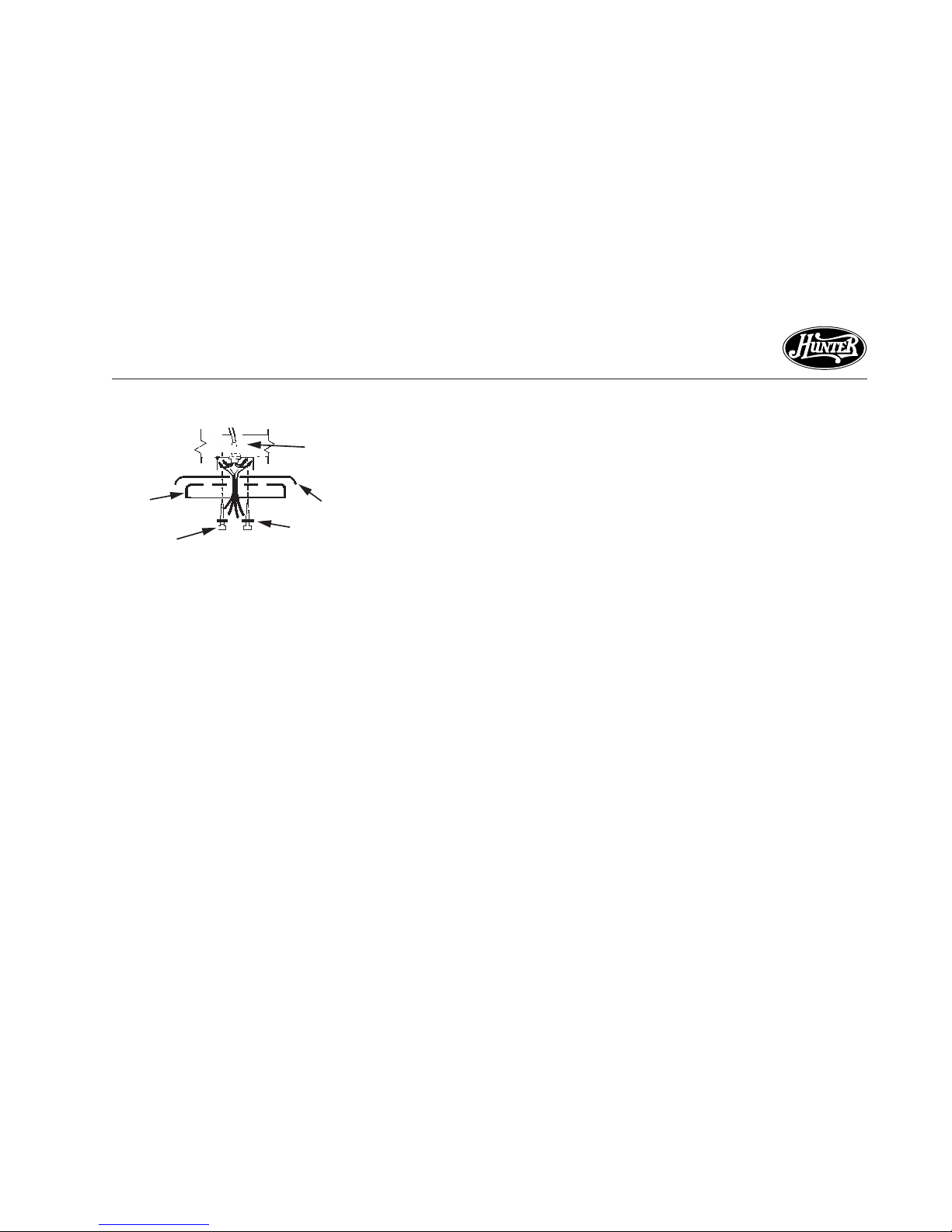
4. Connect the wires as shown in
Figure 5b. To connect the wires,
twist the bare metal leads together. Place a wire nut over the
intertwined length of wire and
twist clockwise until tight as
shown.
Figure 5b - Wiring Diagram
5. Separate the connected wires by
placing the green and white wires
on one side of the outlet box and
the black and the black/white
wires on the other side of the
outlet box.
6. Turn the connectors upward. Push
the wires gently into the outlet
box.
CAUTION
Be sure no bare wire or wire
strands are visible after making connections.
Page 15

15
®
41557-01 3/12/2002
STEP 6 - HANGING THE FAN
Figure 6a - Attaching Canopy to Ceiling
Plate
Figure 6b - Canopy Tabs and Grooves in
Hanger Ball
1. Locate the two canopy screws
you partially installed in Step 2,
sub-step 2 on page 8.
2. Lift the fan from the ceiling plate
hook without breaking the wire
connections.
3. Align the mounting slots on the
canopy with the mounting screws
on the ceiling plate. Lift the
canopy into place so that the ceiling gasket covers the top of the
canopy as shown in Figure 6a.
Rotate the canopy until it drops
into place on the mounting
screws.
4. Install and tighten the third
canopy mounting screw in the
remaining hole by lifting the edge
of the gasket cover. Tighten the
first two canopy mounting
screws.
5. Lift the fan housing towards the
ceiling and rotate the fan until
each canopy tab engages a
groove in the hanger ball as
shown in Figure 6b.
NOTE: If the tabs are already
engaged, do not rotate.
Mounting Hole
Ceiling Gasket
Ceiling Plate
(2) Canopy
Mounting Screws
Canopy
(2) Mounting
Slots
WARNING
Failure to complete sub-steps
1 through 5 could cause fan to
fall.
Groove in
Hanger
Ball
Canopy
Tab
Groove in
Hanger Ball
Page 16

16
41557-01 3/12/2002
®
Figure 7a - Inserting Grommet into Fan
Blade
Figure 7b - Attaching Fan Blade to Blade
Iron
Figure 7c - Attaching Fan Blade to Blade
Iron using Decorative Medallion
feature a decorative medallion as
well as a blade iron. Insert the
assembly screws into the blade
iron, through the blade and into
the medallion, with the blade
sandwiched between the blade
iron and medallion as shown in
Figure 7c.
Hunter fans use several styles of fan
blade irons (brackets that hold the
blade to the fan).
1. Your fan may include blade grommets (see Parts List). If your fan
has grommets, insert them by
hand into the holes as shown in
Figure 7a.
2. Attach each blade to blade iron
using three blade assembly screws
as shown in Figure 7b. Some fans
STEP 7 - ASSEMBLING FAN BLADES
If you used grommets, the blades
may appear slightly loose after
screws are tightened. This is normal.
3. Remove the blade mounting
screws and rubber shipping
bumpers from the motor.
Grommet
Fan
Blade
Medallion
Blade
Iron
Page 17

17
®
41557-01 3/12/2002
4. For each blade, insert one blade
mounting screw through the
blade iron as shown in Figure 7d,
and attach lightly to the fan. Insert the second blade mounting
screw, then securely tighten both
mounting screws.
Figure 7d - Attaching Blade Irons to Hub
of Fan Assembly
Page 18

18
41557-01 3/12/2002
®
STEP 8 - ATTACHING THE SWITCH HOUSING
The switch housing assembly is made
up of three sections: the switch
housing gasket, the upper switch
housing, and the lower switch
housing/light assembly.
ATTACHING THE SWITCH
HOUSING GASKET
1. Locate the switch housing mounting plate, the switch housing
gasket and the upper plug connector as shown in Figure 8a.
NOTE: Your fan may come with
the switch housing gasket
attached to the switch housing
mounting plate.
If the switch housing gasket is attached to the switch housing mounting plate, go to the section "Attaching the Upper Switch Housing."
If the switch housing gasket is not
attached complete the steps below.
2. Identify the top side of the switch
housing gasket by looking for the
raised circular ridge on the gasket. See Figure 8b.
3. With the top side of the switch
housing gasket facing up towards
the motor, align the holes in the
gasket with the spokes on the
switch housing mounting plate.
4. Feed the upper plug connector
through the center opening of the
upper switch housing. Push the
gasket up so that it is seated flush
with the mounting plate.
See Figure 8c.
Figure 8a - Mounting plate and upper
plug connector Figure 8b - Switch housing gasket
Mounting
Plate
Upper Plug
Connector
Gasket
Align Holes
with Spokes
Feed Upper Plug
Through Center
Page 19

19
®
41557-01 3/12/2002
ATTACHING THE UPPER SWITCH
HOUSING
1. Locate the four #6-32 X 1/4"
switch housing mounting screws
in the sack parts.
2. Feed the upper plug connector
through the center hole in the
upper switch housing.
3. Align the holes in the upper
switch housing with the spokes
in the mounting plate.
4. Insert and tighten the four #6-32
X 1/4" screws into the outermost
holes in the upper switch housing.
Figure 8c - Attaching Upper Switch
Housing to Switch Housing Mounting
Plate
ATTACHING THE LOWER
SWITCH HOUSING/LIGHT ASSEMBLY
1. Locate the four #6-32 X 3/8"
housing screws.
NOTE: Depending upon your fan
model, these screws may be installed in the four spokes from
the switch housing mounting
plate, or they may be located in
the sack parts.
2. Install the screws halfway into the
four spokes from the switch housing mounting plate.
See Figure 8d.
NOTE: if these screws came installed, make sure that they are
installed halfway in order to
complete the following steps.
3. Connect the upper plug connector to the lower plug connector
CAUTION
Make sure the upper switch
housing is securely attached to
the switch housing mounting
plate. Failure to properly attach and tighten all four housing assembly screws could result in water entry into live connection area and/or the switch
housing and light fixture falling.
Page 20

20
41557-01 3/12/2002
®
from the lower switch housing
assembly. See Figure 8d.
Note: Both plug connectors are
polarized and will only fit together one way. Make sure that
both connectors are properly
aligned before connecting them
together. Incorrect connection
could cause improper operation
and damage to the product.
4. Align the keyhole slots in the upper switch housing with the housing assembly screws installed in
sub-step 2.
5. Turn the lower switch housing
clockwise until the housing assembly screws installed in substeps 1 and 2 are firmly situated
in the narrow end of the keyhole
slots as shown in Figure 9e.
Tighten all four screws firmly.
6. Partially install two of the screws
into the lower switch housing to
mount the light kit.
Figure 8d - Attaching Lower Switch
Housing/Light Assembly
CAUTION
Make sure the lower switch
housing/light assembly is securely attached to the switch
housing mounting plate.
Failure to properly attach and
tighten all four housing assembly screws could result in the
switch housing and light
fixture falling.
Figure 8e - Light Assembly
7. Install one Max 100 Watt light
bulb.
8. Align the keyhole slots in the light
kit with the screws installed in the
lower switch housing. Refer to
Figure 8e.
9. Turn the light kit clockwise until
the screws installed are firmly situated in the narrow end of the
keyhole slots. Securely install the
third screw and tighten all screws.
Page 21

21
®
41557-01 3/12/2002
Instructions for unassembling the
globe when replacing a light bulb.
1. Unassemble the finial assembly
as shown in Figure 9a.
2. Install one 100 Watt light bulb.
Refer to Figure 9b.
3. Loosely reassemble the finial
bracket, cover plate, and finial.
Refer to Figure 9a.
STEP 9 - REPLACING THE LIGHT BULB
4. Assemble the finial to the bottom of the globe assembly as
shown in Figure 9c. Viewing the
assembly through the globe, line
up the finial bracket with the
tabs in the bottom part of the
globe assembly.
5. Securely tighten the finial.
Figure 9a - Unassembling the finial Figure 9b - Installing bulb Figure 9c - Assembling the finial
Finial Bracket
Finial
Cover Plate
Globe Assembly
Light Bulb
Finial
Assembly
Page 22

22
41557-01 3/12/2002
®
3. The pull chain controls power to
the fan. The chain has four settings in sequence: High, Medium,
Low and Off.
4. Ceiling fans work best by blowing air downward (counterclockwise blade rotation) in warm
weather to cool the room with a
direct breeze.
In winter, having the fan draw air
upward (clockwise blade rotation)
will distribute the warmer air
trapped at the ceiling around the
room without causing a draft.
To change the direction of air
flow, turn the fan off and let it
come to a complete stop. Pull the
reversing switch chain on the fan
to the next position as shown in
Figure 10b. Restart fan.
OPERATING YOUR HUNTER FAN
1. Turn on electrical power to the
fan.
2. There are three pull chains on this
fan; one for fan operation, one
for light operation and one for
reversing the fan.
NOTE: Use the following directions for operating all pull chain
switches.
• Pull the chain slowly to change
settings.
• Release slowly to prevent the
chain from recoiling into the
blades.
• The chain uses a breakaway
connector that separates if the
chain is jerked. If this happens,
simply reinsert the chain into
the connector.
Figure 10a - Air Flow Patterns
Page 23

23
®
41557-01 3/12/2002
Figure 10b - Pull Chain, Light Chain and
Reversing Switch
5. The light pull chain controls the
power to the light fixture. The
chain has two settings: ON and
OFF.
6. If your fan wobbles when operating, use the enclosed balancing
kit and instructions to balance the
fan.
Pull
Chain
Reversing
Switch
Chain
Light Chain
Page 24

TROUBLESHOOTING
Nothing happens; fan does not move.
Noisy operation.
1. Power turned off, fuse blown, or
circuit breaker tripped.
2. Loose wire connections or wrong
connections.
3. Motor reversing switch not engaged.
4. Pull chain switch not “on.”
5. Shipping bumpers still in place.
1. Blade brackets screwed loosely to
motor.
2. Blade screwed loosely to blade iron.
3. Blade cracked.
PROBLEM PROBABLE CAUSE SOLUTION
1. Turn power on, replace fuse, or reset breaker.
2a. Loosen canopy, check all connections
according to STEP 5 - WIRING THE
FAN (turn power off before checking).
2b.Check the plug connection in the
switch housing according to STEP
8 - ATTACHING THE SWITCH
HOUSING.
3. Pull switch chain.
4. Pull switch chain.
5. Remove shipping bumpers.
1. Tighten screws until snug.
2. Tighten screws until snug.
3. Replace all blades.
Page 25

PROBLEM PROBABLE CAUSE SOLUTION
Noisy operation (continued).
Excessive wobbling.
Note: When switching from medium
to low speed, you may notice some fan
wobble. When the fan stabilizes at low
speed, wobble will disappear.
4. Using non-approved speed control.
5. Switch housing is loose.
1. Unbalanced blades.
2. Loose blades or blade irons.
3. Fan not secure on hanger assembly.
4. Fan hanger ball not seated in
canopy tabs.
4. Change to approved speed control.
5. Check and tighten screws to the
switch housing mounting plate and
to the upper and lower switch
housing.
1. Use balancing kit included with fan.
2. Tighten all screws.
3. Turn power off, support fan very
carefully, loosen canopy and hang
correctly.
4. Turn power off, support the fan very
carefully, and check that the hanger
ball is properly seated.
continued
Page 26

26
41557-01 3/12/2002
®
If you have tried these troubleshooting solutions and still have trouble, call 901-248-2222 or visit our
Web site at http://www.hunterfan.com.
PROBLEM PROBABLE CAUSE SOLUTION
Light Fixture will not work 1. Pull chain switch is in OFF position.
2. Light Fixture is not wired properly.
1. Pull the light chain one time.
2. Double check the wiring according
to "Step 5 - Wiring the Fan."
Page 27

27
®
41557-01 3/12/2002
Page 28

Hunter Fan Company
2500 Frisco Avenue
Memphis, TN 38114
®
 Loading...