

Page 1
ET System
Evapotranspiration Sensor and
Module for Hunter Controllers
®
with SmartPort
Owner’s Manual and Programming Instructions
Page 2

TABLE OF CONTENTS .............................................................................................................................
Introduction ...........................................................................1
ET System Components .........................................................3
System Overview and ET System Operation ..........................3
Installing the ET Sensor .........................................................4
Additional Tools and Materials ........................................4
Choose the Location .......................................................4
ET Sensor Wiring ............................................................5
Prevailing Wind Compensation .......................................5
Metal Fence Pole .............................................................6
Wooden Post ..................................................................6
Wall or Eave ....................................................................6
Installing the ET Module ........................................................7
ET Module Wiring ...........................................................7
SRC or SRC Plus Controller Connection .........................8
Pro-C Controller Connection ...........................................8
ICC Controller Connection ..............................................8
Remote Control Connection ............................................9
ACC Controller Connection .............................................9
Test ...............................................................................11
Maintaining the ET Sensor ...................................................11
Programming and Operating the ET Module ........................12
General Operating Tips .................................................12
Setup Overview .............................................................13
Global % Setting ...........................................................13
Initial Soil Deficit ...........................................................13
International Users – Metric Setting .............................13
Controller Type .............................................................14
Prepare the Controller ...................................................14
Set Time/Date ...............................................................15
Set Daylight Savings .....................................................16
Plant Type .....................................................................16
Maturity ........................................................................17
Type ..............................................................................17
Variety...........................................................................17
Site Info ........................................................................19
Slope ............................................................................19
Soil ...............................................................................19
Sun ...............................................................................20
Sprinkler Type ...............................................................20
Precip ...........................................................................20
Water Days ...................................................................21
Daily Start Time ............................................................22
WiltGard™ .....................................................................22
Rain Setting ..................................................................24
ET Setup .......................................................................25
Automatic .....................................................................26
Watering History ...........................................................27
View Sensor Date ..........................................................29
Reset ............................................................................29
Troubleshooting ............................................................30
Specifications .......................................................................34
ET System Compatibility List ...............................................34
Dimensions ..........................................................................34
FCC Notice ...........................................................................34
Page 3

INTrOduCTION .......................................................................................................................................
The Hunter ET System allows an irrigation program to be created automatically, based on local climate conditions. The program is then operated
via a compatible irrigation controller’s Program A (except ACC controllers, see page 14) and runs automatically, on water days and at start times
set by the system operator. Compatible controllers are Hunter Models SRC/SRC Plus, Pro-C, ICC, and ACC with SmartPort
ET System uses sensors to determine the local “evapotranspiration” (ET) rate of turf and plants. This is a formula which calculates how much water the plants have lost, or consumed, due to local atmospheric conditions. Each ET System can be customized by station (or “zone”) for specific
plant, soil, and sprinkler types.
The result is a new, water-efficient irrigation program every water day, based on local weather conditions.
Once installed, the ET-controlled zones are programmed from the ET Module, rather than the controller itself. The ET Module will display the new
program data for the climate-based irrigation.
The ET System allows manual station starts from the controller, and will also permit connection of an ICR or SRR remote control receiver.
This product is intended for turf and landscaping applications only, not intended for agricultural or scientific use.
Use the ET System Worksheet. One is included with each ET System, and this can also be downloaded free of charge from the Hunter Industries
web site (www.hunterindustries.com at the ET System product page). The ET System Worksheet will help you organize and record your station
settings. This will also help to determine and track any adjustments you may make to the watering settings. If you need Technical Support, the
Hunter technician will also need this information.
®
technology.
1
Page 4
C.
A.
D.
E.
B.
2
Page 5

ET SySTEm COmpONENTS ...................................................................................................................
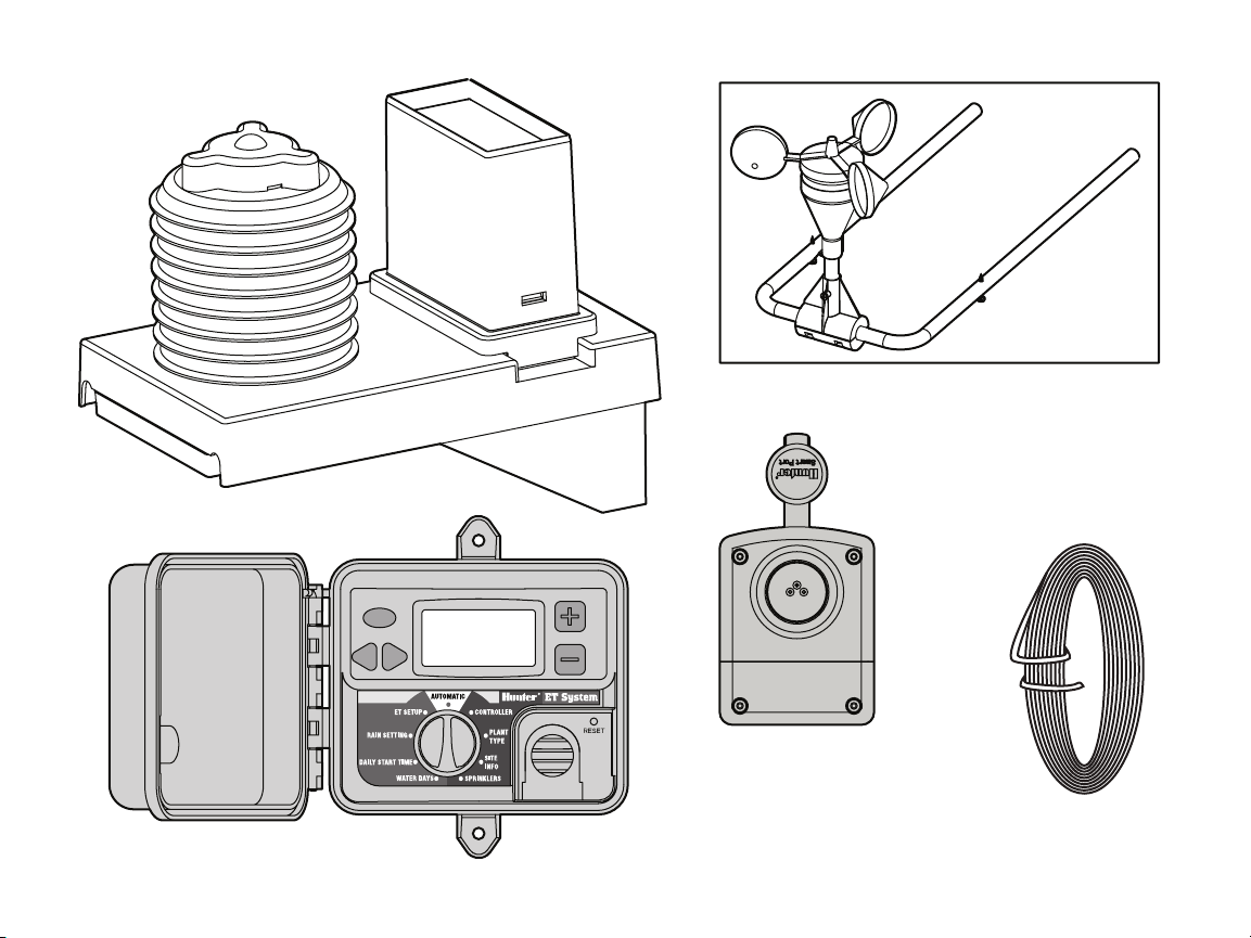
ET System has two major components, and one optional accessory. All
ET System components are low voltage (24 VAC or less).
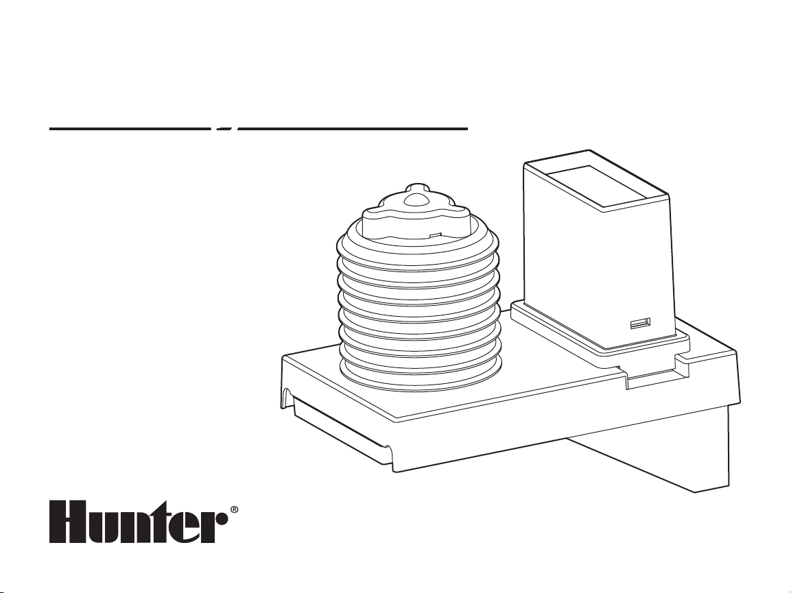
A. ET Sensor
Sensor platform wired to the ET Module, which senses local
conditions. For external mounting up to 100 ft/33m from the Module. Pole adapters included (requires other hardware for various
mounting options).
B. ET Module
Electronic control and user interface for the ET System.
C. ET Wind (Optional)
Optional anemometer which senses wind speed. Provides more
sensitive ET measurement, especially in arid climates.
D. ET/ACC Adapter (Included)
For connection with ACC series controllers. The adapter is not
required for use with Hunter ICC, Pro-C, and SRC family
controllers.
E. ET Wire
100' (33mm) two-conductor direct burial for connection to ET
Sensor
SySTEm OvErvIEw ANd ET SySTEm OpErATION .........................................................................
The ET System can be simply and easily installed with any Hunter
SmartPort®-equipped irrigation controller. The System consists of the
ET Sensor, installed in an area typical of the irrigated plants, and the
ET Module interface enclosure, installed next to the irrigation controller.
The ET Sensor measures solar radiation, air temperature, and relative
humidity, and calculates the daily Evapotranspiration factor (ET) for
the irrigation zones. This represents the amount of water lost by the
plants to local climatic conditions, which needs to be replaced by
irrigation.
The optional ET Wind sensor will add evapotranspiration loss due to
wind, along with automatic wind shutdown capability.
The ET Sensor also includes a Rain Gauge, which measures rainfall in
either hundredths of an inch, or in millimeters.
Rainfall will stop automatic ET irrigation that may be in progress. A
percentage of the rainfall itself will be added to the soil and subtracted
automatically from the automatic irrigation, to prevent waste.
The ET Module receives the data from the ET Sensor, and applies it
to the individual zones of irrigation. The ET Module has settings to
customize each zone’s plant, soil, and sprinkler types, so that ET data
can be applied proportionately for each unique irrigation requirement.
The ET Module is wired into the controller’s SmartPort and creates
irrigation run times to only replace the amount of water the plants
have lost.
ET Module works by running stations through the local controller. It
will clear Program A in the local controller (except in ACC controllers),
and it will then run the ET run times with manual commands. Program
A is no longer available for "traditional" irrigation scheduling.
How ET System Decides to Water: Using the local ET Sensor readings
and the ET Module’s database of station information, ET System predicts the Management Allowable Depletion of water (MAD) available to
each plant type.
Each day, ET System looks at the current depletion level, ET rate,
plant type (crop coefficient and root zone), and whether the next day
is an allowable watering day. The decision to start a specific station
is also based upon a minimum irrigation amount, to prevent shallow
watering. Deeper watering events encourage healthy root systems and
plant growth. The calculation for minimum sprinkler runtime is based
upon the soil type and capacity, where typically the MAD is above
30-50%. For the worst-case scenario, sandy soil with spray heads, the
minimum runtime would then be approximately 7 minutes.
3
Page 6
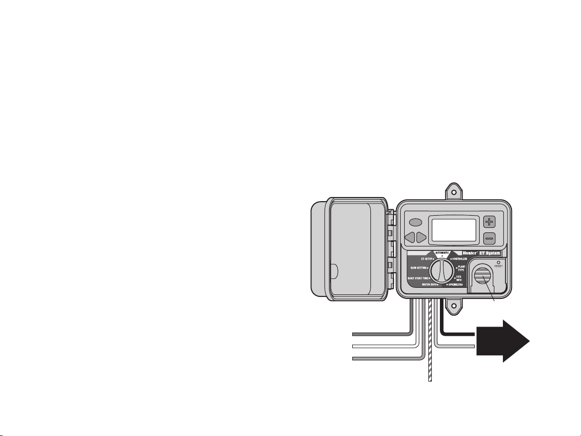
INSTALLINg ThE ET SENSOr................................................................................................................
ET Sensor
Additional Tools and Materials
The ET system is supplied with 100’/33m of wire for connection of the
ET Sensor. This wire has been specially tested for ET installations and
is approved to 100’/33m max.
If any other wire is to be used, Hunter recommends 2 x 18 AWG/1mm
wire rated for direct burial, color-coded or other wise marked to
identify the separate conductors. The ET signal is a low-voltage DC
and the conductors must be distinguished from each other to maintain
polarity. Either stranded or solid wire is acceptable (stranded is more
flexible and resists breakage). The ET signal is rated to 100’/33m max
and is not tested or approved to any greater distance.
Choose the Location
ET Sensor should be placed in an area representative of the plants it is
designed to irrigate.
The ET Sensor should be post or pole-mounted in a full-sun turf
grass area, approximately 6 ft./2m above the grass, with approximately 6 ft./2m of turf grass surrounding it on all sides. The ET
Sensor weighs approximately 6 lbs./2.5kg.
This may not always be practical, so choose the actual location
according to the following guidelines:
a) ET Sensor must be mounted within 100 ft./33m of the ET Module
and the controller.
b) Avoid positioning ET Sensor over large areas of concrete, asphalt,
roof tile, or shingles. These surfaces will cause the sensors to
read much higher levels of ET than plants.
c) Choose a sunny location between 6 and 20 feet (2 and 7m) above
the ground.
d) Do not mount the sensor where it will be hit by sprinkler spray or
other irrigation!
4
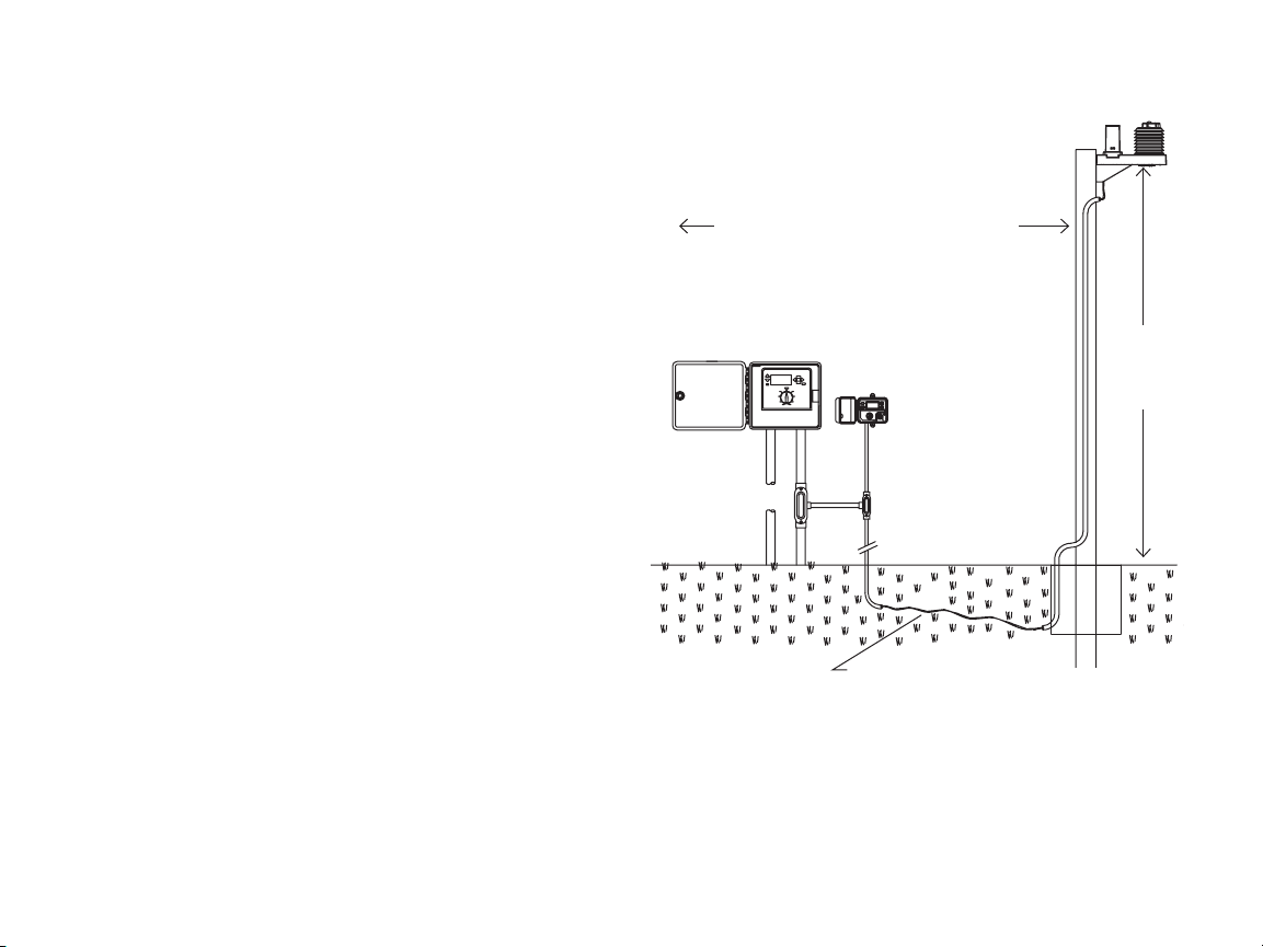
15 ft/5m Clearance From Any Structure
ICC Controller
ET Module
ET Sensor Wire (Included with ET
System) 100 ft./30m, maximum
e) Do not mount the ET Sensor under a ledge or overhang, and avoid
placing it directly under tree canopies. ET Sensor needs un-
blocked sun and rain to function correctly!
f) Do not mount the ET Sensor within falling distance of power
lines! High voltage shocks can injure and kill.
6 ft/2m
Above
Turf,
Minimum
Page 7
g) Position the ET Sensor where it can be reached for occasional ser-
vice. The rain gauge should be checked and cleaned once a month
during the warmer months, to ensure that it is free of debris.
h) Avoid mounting sensor near any high intensity light, heat or infra-
red sources as this may add excess ET amounts over time.
The ET Sensor is designed to adapt to steel fence poles (mounting
adapters included, requires 2 x 2"/50mm
2
U-bolts), 4x4"/100mm2 (or
larger) posts, or eaves or walls.
Metal poles or weather-treated wooden posts are preferred, since
ET measurements will be somewhat less accurate if the sensor is
wall or eave-mounted.
ET Sensor Wiring
Locate the screw terminal strip. Connect the two long conductors
(green and black) to the appropriately labeled terminals.
If an ET Wind Sensor is to be installed, this is also the time to connect the wires.
Prevailing Wind Compensation
If ET Wind will not be connected,
a factor for average prevailing
Green and
Black Wires
(ET Module)
Before mounting the ET Sensor, connect the wires to the terminal
strip. This operation is much easier on the ground, prior to mounting
the sensor.
Locate the wiring compartment cover on the bottom of the ET Sensor.
This is a trap door, secured with 2 screws. Remove the wiring com-
White Wire
Blue Wire
(ET Wind only)
partment door screws and set in a safe place, and remove the wiring
compartment door.
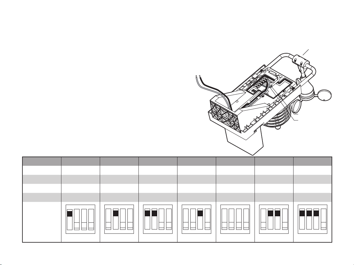
Average Wind Factor Settings. Switch #4 is not used, and position does not matter.
Avg. Wind 1mph 2mph 3mph 4mph 5mph 6mph 7mph
DIP setting 1.6kph 3.2kph 4.8kph 6.4kph 8kph 9.6kph 11.2kph
SW 1 On Off On Off Off Off On
SW 2 Off On On Off Off On On
SW 3 Off Off Off On Off On On
ET Wind
ON
OFF
1 2 3 4
1 2 3 4
1 2 3 4
1 2 3 4
1 2 3 4
1 2 3 4
1 2 3 4
5
Page 8

winds in the installation area can be entered while the wiring door is
removed. The factory default setting is 5 mph (8 kph). With the wiring
cover removed, a DIP switch is visible allowing other prevailing
average wind speeds to be set, according to the Table 1 (note
that Switch 4 is not used).
If the optional ET Wind sensor is installed, mount
the ET Wind sensor according to its instructions,
and connect the blue and white conductors from
the ET Sensor to the appropriately labeled terminals and secure their screws. Do not reverse the
blue and white wire connections from ET Wind…
connect as shown!
Replace the wiring compartment door and secure
with the screws.
Metal Fence Pole
Steel adapters are supplied for most popular sizes
of galvanized steel fence posts, 2" diameter and
smaller.
Additional materials (not supplied): 2 x 2" galvanized or stainless steel U-bolts, 3" long or greater
4 nuts and washers for U-bolts
Bag of concrete
If pole is new construction for specific purpose
of mounting ET Sensor, dig approximately 12" x
12" hole and fill with approximately one 90 lb. bag
of concrete, or place as required by local code.
Insert pole, check with level and straighten, and
brace until concrete is firmly set.
Insert U-bolts around pole through steel pole
adaptors, and through mating holes in ET Sensor
back plane. Add washers, thread nuts onto U-bolt,
and tighten. Do not overtighten.
Route ET Sensor wire to ground surface or burial trench, and run back
to ET Module.
6
External mounting in outdoor low voltage conduit
(for the above-ground exposed portion of the wire
run) is recommended for protection from the elements.
Wooden Post
Additional materials (not supplied): 4x4"/100mm
pressure-treated, outdoor, direct-burial grade
4x4"/100mm
2
or larger post.
100mm x 6mm dia. x 3,8cm long galvanized or
stainless steel lag bolts and washers
Nut driver for lag bolts
Bag of concrete
Dig approximately 12" x 12"/30cm x 30cm hole (or greater, as
local code dictates) and fill with approximately one bag of concrete.
Insert post, check with level and straighten, and brace until concrete
is firmly set.
Level, mark, and drill pilot holes for 4 lag screws through back of ET
Sensor holes. Insert lag bolts and washers through mounting hole in
backplane of ET Sensor and tighten. Do not overtighten.
Route ET Sensor wire to ground surface or burial trench, and run back
to ET Module.
External mounting in outdoor low voltage conduit (for the aboveground exposed portion of the wire run) is recommended for protection from the elements.
Wall or Eave
Additional materials (not supplied): 4 x ¼" dia. x 1.5" (100mm x 6mm
x 40mm) long galvanized or stainless steel lag bolts and washers.
Nut driver for lag bolts.
Level, mark, and drill pilot holes for 4 lag screws through back of ET
Sensor holes. Insert lag bolts and washers through mounting hole in
backplane of ET Sensor and tighten. Do not overtighten.
Route ET Sensor wire to ground surface or burial trench, and run back
2
Page 9
Orange, or Blue-And-White-Striped
in some versions
Controller Connections
(ET System Only)
Blue: REM
White: AC2
Red: AC1
To ET Sensor
Green
Black
to ET Module. External mounting in outdoor low voltage conduit (for
the above-ground exposed portion of the wire run) is recommended
for protection from the elements.
In all cases, ensure that any exposed wire loop from the ET Sensor to
INSTALLINg ThE ET mOduLE ..............................................................................................................
immediately next (6 ft./2m) to the Hunter SmartPort-equipped irrigation controller (including models SRC, Pro-C, ICC, and ACC). The ET
Module is low-voltage only and does not require a separate highvoltage power connection.
The ET Module is connected to the ET Sensor via the two conductor
sheathed wires supplied with the ET System (up to 100 ft./30m away),
and then wired into the SmartPort wiring terminals inside the controller.
To wall mount the ET Module, choose a location within 6 ft./2m of the
controller. Avoid direct sunlight when possible (to enhance visibility of
the LCD display). Verify that the wallboard construction is of sufficient
strength to securely mount the small, lightweight enclosure.
The 6-conductor umbilical cord extends through the shielded hole in
the bottom of the enclosure. Verify that it remains clear and accessible
when securing the enclosure to the wall.
Use two anchors or self-tapping screws of minimum #12 (5.5mm)
diameter to secure the ET Module enclosure to the wall.
Turn off AC power to the irrigation controller, before connecting the
ET Module to the controller! The ET System receives its power from
the SmartPort connection to the Hunter controller. Do not connect the
ET Module to the controller while AC power is turned on.
ET Module Wiring
The 6-conductor umbilical cord from the ET Module is color-coded to
simplify connections.
Do NOT connect 110/230V high-voltage power to the ET System!
Make all wiring connections with approved butt splices or wire nuts
for the ET wire, and place the splices in a suitable junction box. Conduit is recommended for both indoor and outdoor installations.
the wire routing conduit does not swing freely in the wind, as this will
shorten its life.
The ET Module is designed to be wall-mounted, either in or outdoor,
Install CR2032 backup battery for date/time backup in event of power
failure (battery included with mounting hardware). Batter y must be
installed with + visible, facing toward the installer.
If connecting the ET System to an ACC series controller, see ACC
section for special installation instructions.
ICC, Pro-C, and SRC controllers (ACC special instructions in next
section): Connect the supplied wires from the ET Module to the ET
Install CR2032 lithium batter y (included)
under cover for time/date backup.
Install CR2032 battery
7
Page 10
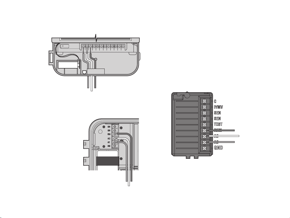
AC AC RRSCMV 123456
9 V Battery
RESET
BlueRed
White
BlueRed
White
Blue
Red
White
Sensor with appropriately sized butt splices or wire nuts. These two
wires may be extended up to 100 ft./30m to reach the sensor.
SRC or SRC
Plus Controller
Connection
If no wireless
remote control
receiver will be
installed, the
Orange wire
(or Blue-AndWhite-Striped
wire in some
versions) from
the ET Module
is not used.
Connect the red wire from the ET Module to the bottom left of the two
terminals on the power module labeled “24VAC” (or just AC, on older
units).
Connect the white wire from the
ET Module to the second to the
right of the two terminals on the
power module labeled “24VAC” (or
just AC, on older units)..
Connect the blue wire from the
ET Module to the terminal in the
controller labeled “R”.
If no wireless remote control
receiver will be installed, the blueand-white striped wire from the ET
Module is not used.
Pro-C Controller Connection
Connect the red wire from the ET
Module to the terminal in the controller labeled AC1.
8
Connect the white wire from the ET Module to the terminal in the
controller labeled AC2.
Connect the blue wire from the ET Module to the terminal in the controller labeled REM.
ICC Controller Connection
Connect the red wire from the ET Module to the bottommost of the
terminals on the power module labeled “AC”.
Connect the white wire from the ET Module to the upper of the two
terminals on the power module labeled “AC”.
Connect the blue wire from the ET Module to the terminal in the controller labeled REM.
Page 11

SmartPort
for ICR Receiver
Blue: REM
Connect orange
(or blue-and-white-striped)
wire from module,
to blue wire from SmartPort
White: AC2
Red: AC1
To ET Sensor
Green
Black
Controller Connections
(SmartPort with ET and ICR)
Remote Control Connection
If a remote control (either Hunter ICR or SRR) receiver is to be connected, connect the Orange wire (or Blue-And-White-Striped wire in
some versions) from the ET Module, to the blue ICR/SRR receiver
wire. The SmartPort wiring that connects ET Module to the controller
will complete the connection for the remote receiver.
ACC Controller Connection
The ET System is shipped with a special adapter for use with the ACC
series of controllers.
The ACC controllers have an integrated SmartPort for remote receivers
(such as the Hunter ICR remote control) on the side of the cabinet in
the metal cabinet configurations, and inside the pedestal in the plastic
pedestal configurations.
All ET System connections are made within the enclosed ET/ACC
adapter, which is then plugged into the SmartPort. The adapter allows
both ICR remote receivers and the ET System to be connected to the
ACC controller at the same time.
When installing ET System with an ACC controller, the ET Sensor connections are also made at the terminal strip inside the adapter, NOT to
the ET Module cable directly. This is only true for ACC connections.
9
Page 12

To ET Sensor
To
ET Module
Wiring
Harness
Blue
Orange (or Blue-AndWhite-Striped)
Red
White
Green
Black
Green
Black
Installation
Remove the screws holding the terminal strip cover on ET/ACC
adapter.
Connect the red, white, and blue wires from the ET Module (in that
order) from left to right, on the first three terminals, as shown.
Connect the Orange wire, (or Blue-And-White-Striped wire in some
versions) from the Module to the terminal as marked.
Twist the ends of the green wires from the ET Sensor and the ET Module together, and connect them together to the terminal as marked.
Twist the ends of the black wires from the ET Sensor and the ET
Module together, and connect them together to the last terminal as
marked.
10
Plug the male pin side of the ET/ACC Adapter into the SmartPort
receptacle on the ACC controller. ET connections are now made.
To use an ICR receiver with the ACC through the adapter, it is only
necessary to plug the ICR receiver into the receptacle on the adapter,
and issue commands normally.
If ICR commands are sent while ET
System is irrigating automatically,
and other programs are already running, it is possible that the ICR command will be ignored (if it violates
the ACC maximum of 6 simultaneous
stations). Likewise, if 6 events are
already running in the ACC when
the ET Start Time is reached, the ET
events may be missed. Avoid overlapping the ET Start Time with multiple
stations.
Leave enough slack in all wires to
allow for expansion and contraction in temperature extremes. Secure
the wire splice points to the inside of the junction box or controller, to
create a strain relief.
Reapply AC power to the irrigation controller, and observe the display
in the ET Module. The display should illuminate and show a welcoming screen, followed by information about the ET System.
The ET System will sense rain and freezing automatically with its own
sensors, and will terminate irrigation when necessar y. If this occurs,
the display will show “RAIN PAUSE” or “FREEZE PAUSE”.
ET System will shutdown irrigation when the temperature drops to
37°F/2.7°C. This is not programmable. Temperature shutdowns are
a “pause” mode, and the system will resume watering when the temperature rises back above the shutdown amount.
If existing Clik sensors are removed, the Clik sensor inputs should
have the original jumper replaced, or the sensor connection should be
jumpered with a short piece of wire.
Page 13

If ET WIND is connected, ET System will also detect windy conditions
and shutdown automatically at preset wind levels. If this occurs, the
display will show “WIND PAUSE”.
The ET Wind will shutdown irrigation when the hourly average exceeds
15 mph/24kph. This is not programmable. Wind shutdowns are a
“pause” mode, and the system will resume watering when the average
wind speed falls below 15 mph/24kph again.
The Sensor Bypass switch on Hunter controllers will have no effect
on the ET System, or any of its Pause modes. This switch only affects
external “Clik” sensors for other programs.
Installing other sensors to the controller.
The ET Sensors can stop ET-based irrigation, which is run through
controller program A (except ACC controllers).
ET Sensors will NOT stop irrigation running in the controller’s B, C, or
other programs.
Hunter Industries model Mini-Clik and Rain-Clik, or other sensors, can
be used to stop irrigation in programs B, C, etc. and are required if
those programs are used, and need to stop watering on sensor input.
The ET System does not sense flow, but may not per form correctly
with Flow-Clik installations, unless the Flow-Clik is wired into the
common ground to the valve connections (instead of to the controller’s sensor input). Contact Hunter Technical Services if it is necessary
to use a Flow-Clik together with the ET System.
Troubleshooting: If the ET Module screen does not illuminate,
check all wiring connections. Verify that the red wire from the ET
Module goes to AC1, and that the white wire goes to AC2, in a
Pro-C controller.
In the SRC controllers, the red wire is the left-most of the two AC
connections.
In the ICC controller, the red wire must be the bottommost of the two
AC connections.
Warning: The use of toners and line voltage testers on field wiring may
damage the ET System if it is connected to the controller. It does not
matter if the power is off to the controller. If any device is connected
to the valve wiring which produces voltage, the ET System must be
physically disconnected from the host controller.
Sensor Fault: If the ET Module display shows Sensor Fault, check
connection between ET Module and ET Sensor (green and black wires
or equivalents). Solid conductor wire is prone to breakage from rough
handling. If wires appear correctly installed and Sensor Fault persists,
check the Sensor wiring with a DC voltmeter – the voltage reading at
the black and green terminals on the sensor should be between 9 to
15VDC.
Test: The ET Module can run a test with the host controller to check
the SmartPort wiring from ET System to the controller. This will
cause Station 1 to run for up to two minutes if successful.
Press and hold the recessed Reset button with a ballpoint pen tip or
similar item.
Press the left 3 buttons on the ET Module (STA plus left and right arrows) at once, and hold them.
Release the Reset button.
Release the left 3 buttons.
This should cause Station 1 on the controller to activate for approximately 2 minutes.
The test will be visible in the ET Module display.
If the test is successful, Station 1 will also appear active in the controller display. This verifies that the SmartPort wiring connection from
the ET Module to the controller is correct.
If station does not activate in controller display (but appears in ET
Module), check SmartPort wiring, in particular the red, white and blue
wire connections.
mAINTAININg ThE ET SENSOr .....................
The ET Sensor is designed for outdoor use, but must be kept clean to
function correctly. Wiping the platform and sensors down with a clean cloth
every 30 days is recommended.
11
Page 14

Do not use harsh chemicals or abrasives, particularly on the clear plastic solar radiation lens. It is very important that this sensor be kept clean
and dust-free to record sunlight accurately.
The rain gauge may gather dust and debris, and should also be cleaned out every 30 days.
Solar Radiation
Sensor
Rain Gauge
prOgrAmmINg ANd OpErATINg ThE ET mOduLE ......................................................................
Station Advance Button
Left/Right Navigation Buttons
Dial
General Operating Tips
ET is reactive. You do not set the minutes (as in traditional controllers). ET looks at the weather, and calculates the minutes for you. You
see what it did after the fact (Station Histories).
If you want more or less water, change either:
1. Global % Adjustment (ET Setup dial position). This will change the
amount of watering for all stations, by a percentage.
Plus/Minus Buttons
Reset Button
Lithium Battery Cover
(CR2032, in box)
12
Page 15

2. Station settings (Plant, Site Info, and Sprinkler dial positions).
This information controls how each station is calculated to water.
Individual stations can have their settings changed to produce the
desired results.
It can take several weeks to dial in a new system for desired performance. Make your best effort at the original setup information, but
observe the results. It is common for adjustments to be made in the
start up period.
Enter all settings and track your changes on the ET System Worksheet.
The ET Module has a backlit LCD display, a dial, and 5 buttons. There
is also a recessed Reset button, and a removable lithium
battery cover.
The display is backlit whenever the 24V power (from the SmartPort)
is present.
When power is initially turned on with the dial in the Automatic position, the display will momentarily show a welcome screen, and will
then show the Date and Time and the Current ET. Initially, this may
be 0.00 until the sensor has accumulated enough data to generate an
automatic ET (this may take up to one hour).
11:00AM 00SEP05
DAILY ET: 0.10 IN
Setup Overview
Setup is simplified by following the dial clockwise all the way around,
and entering data for each station until setup is complete.
First, select the controller type and station size (international users,
select Metric measurement first, at the ET Setup dial position).
Then, each station will receive its own data for Plant, Soil, and Sprinkler types.
Other options related to automatic operation are set, and finally the
dial is returned to the Automatic position (straight up, or 12 o’clock
position). The module will now be ready to run ET-based automatic
irrigation.
The ET Module dial must be left in the Automatic position, or the ET
program will not irrigate! If the ET System is watering, moving the
dial from the Automatic position will cause it to stop.
Global ET % Setting
The ET System uses the modified Penman-Monteith equation to
determine moisture loss from evapo-transpiration. The %of actual ET
used is now adjustable. This allows irrigation to be adjusted based on
a percentage of measured ET, and allows the system to run “wetter” or
“drier” to customize performance for specific landscapes.
ET System is preset to operate with 80% of ET. However, this can be
adjusted (in 1% increments) from 10% to 150%. The higher the %,
the "wetter" the system will run. The adjustment is applied equally to
all stations, which are further modified by their individual settings
(Plant, Site Info, and Sprinkler types). This factor may compensate
for non-ideal mounting conditions, where the sensor cannot be placed
according to ideal specifications.
Hunter recommends obser ving performance carefully over the first
weeks of operation and adjusting the percentage to tweak system
performance.
Initial Soil Deficit
ET System assumes an initial soil deficit of .1” of water, meaning the
soil is neither saturated nor dry. This relatively neutral value prevents
excessive watering after initial installation.
If soil is very dry when the system is installed, it may be desirable to
run all stations from the host controller first, with Manual Program
starts, for a “normal” watering. Do not over water, but bring the soil to
a naturally moist state before beginning ET operations.
International Users – Metric Setting
ET System is set to Inches-style measurement, but can be quickly set
to Metric. Turn the dial to the ET Setup position, before entering the
other setup screens.
13
Page 16

ENABLE ET: YES
UNITS: INCHES
ET SOURCE: SENSOR
ET ADJUST: 80%
Use the right arrow key to advance to the UNITS: INCHES position.
Use the +/- keys to change the display to METRIC.
Turn the dial to save the setting. For initial setup, turn the dial to
the Controller Type dial position. Millimeters will now be used in the
displays in other dial positions.
Controller Type
Use the +/- keys to enter the number of stations you will be controlling with ET. Press and hold either key to accelerate the setting.
At the Controller Type dial position, select the type of Hunter controller to which the ET Module is connected. Use the +/- keys to cycle
through the valid selections: SRC, Pro-C, ICC or ACC.
When the correct controller is displayed, use the Left/Right arrow keys
to advance to the station size.
The ET Module will not allow a number greater than the maximum size
for the selected controller.
NOTE: Enter only the number of stations you wish to control with
ET–they will all run through Program A (except in the ACC controller).
It is possible to allow other stations to run in the controller’s other
programs (B, C, or higher in some models) with traditional programs.
These other programs will always run for the set Run Time in hours:
minutes.
Note that these other programs will not “stack,” and their Start Times
must be set to a safe time, after all ET stations will have completed.
The ET System Start Time will cancel any other programs that may
be running, and will prevent any new programs from beginning, until
the ET watering is complete (except in the ACC controller). The best
practice is to calculate the longest likely run times for the ET adjusted
14
stations, and add the total to the ET System Start Time. Set the Start
Times for any other programs after this longest possible ET water
window, or set them to complete before the ET Start Time.
Prepare the Controller
The ET System connects to any Hunter SmartPort®-equipped irrigation
controller. The controller must be properly prepared to work with ET
prior to use.
ICC, Pro-C, SRC (or SRC Plus) Controllers
• Program A will be erased. ET System will use the controller’s
Program A as a storage area for its ET-based run time information. Any information in the controller for Program A will be lost,
after ET System communicates with it. If the Program A information was valuable, it is a good idea to write the day/start/run time
information down before connecting ET System.
ET System will not begin to water immediately, and Program A
will not be cleared until ET System decides to water. The system
begins with an initial soil deficit of .1"/2.54mm. This means it assumes the soil is fairly moist, and that plants and soil are in good
condition.
The local ET will then begin to build up, meaning the soil will
become drier. When the moisture level is low enough, ET System
will schedule irrigation and then Program A will be erased. This
may take several days
• Adjust other Program Start Times. Programs B, C, and (in ICC
only) D can still be used when ET System is connected, but not at
the same time as the ET station program coming from the ET System. If it is still necessary to use the other programs, adjust their
start times so that they will never overlap the longest program that
ET System is likely to create. When ET starts running stations, it
will automatically cancel all other programs (including D in the
ICC) that may be running at that time, and will prevent any other
programs from starting.
• Move the Station wires (if necessary). ET System will control
the number of stations it is told to control, but does not know
Page 17

where they are in the host controller. It will assume it controls
from station 1, to the highest numbered station it knows about, in
consecutive order. If there are stations for which ET control is not
desired, their wires should be moved to the highest-numbered station positions. Be sure to change the Pump/Master Valve settings
for those stations if applicable (Pro-C and ICC only).
Example: A 9-station Pro-C controller has two stations, 3 and 5, for
which ET control is not desired. At the Controller dial position, ET
System is told that it is a 7-station system. Since ET System will assume control of the first 7 stations, move the valve wires for stations
3 and 5 to stations 8 and 9, and move the former stations 8 and 9 to
the 3 and 5 positions. ET System cannot skip stations. It will accept
any number of stations, from 1 to xx, regardless of the controller
type selected.
ACC Controllers
The Hunter ACC controller is compatible with ET System, but setup
is somewhat different. See installation section for use of the ET/ACC
adapter.
• Program A is not erased: ET System will not affect controller
Program A directly. It will issue its run commands directly from
the ET Module.
• Overlapping (with other Programs): ET System stations may
overlap other ACC controller programs which happen to be running (within the controller’s or user-program’s maximum number
of overlapping stations), which is not possible in ICC, Pro-C, or
SRC. However, if ET System and the ACC controller try to run
more than 6 stations (or the user programmed maximum) at once,
ACC will cancel any irrigation over the maximum, and watering
may be postponed or lost. Avoid overlapping ET with other programs unless absolutely necessary, to prevent confusion.
• Flow: ACC controllers may also be equipped with flow meters, and
high or low flow shutdowns will not be known to the ET System (it
will think it has watered correctly). Compensate for any lost irrigation by manual watering, after the flow condition has been fixed.
• Move the Station wires (if necessar y). This applies to ACC as it
does to the other controllers: all stations for the ET control should
be first, in consecutive order from station 1 to the highest number
to be controlled by ET, followed by any non-ET stations that the
ACC will run in other programs.
Set Time/Date
The ET Module keeps its own time, separately from the irrigation
controller, and the current date/time must be set at the Controller Type
dial position.
After the station size has been set correctly, use the right arrow key to
advance to the hour position.
Use the +/- buttons to enter the correct hour. Press and hold either
key to accelerate the setting.
Use the right arrow key to advance to the minute position, and use
+/- to enter the minute.
Use the right arrow key to advance to the AM/PM setting, and use +/to finish the time setting.
AM/PM International Time definitions (in 24-hour clock terms):
0000 – 1200 = AM (Latin Ante Meridiem, before noon)
1201 – 2359 = PM (Post Meridiem, after noon)
Midnight = 12 AM
Noon = 12 PM
Continue to set the date with the right arrow key. Set the date, month,
and year separately, using the +/- at each position, and the right arrow
to move positions (dd/mm/yy).
Set Daylight Savings
ET Module can automatically adjust for Daylight Savings time
changes.
After the time and date are set, use the right arrow key to advance to
the Daylight Savings position.
Use the +/- keys to select either USE or DO NOT USE.
15
Page 18

If Daylight Savings is set to USE, the time will change forward one
hour at 2 AM on the last Sunday in March, and will change backward
one hour at 2 AM on the last Sunday in October.
When the Controller Type settings are complete, turn the dial to
save the information. For initial setup, proceed to the Plant Type
dial position.
Individual Zone Setup
Once the general setup settings have been made, it is necessary to
enter the characteristics of each station, or zone, of irrigation in the
ET Module.
The 3 dial positions Plant Type, Site Info, and Sprinkler Type need to
be completed for each zone. This may be done one of two ways:
1) Go to each dial position and advance through all stations. Enter
the Plant Types for each station, turn to Site Info and advance
through all stations again, and finally turn to the Sprinkler Type
position and repeat for all stations.
2) It is easier for some to set all characteristics for each zone, one at
a time. ET System will stay on the same selected station through
all 3 dial positions, so you can select a station and choose the
Plant Type, turn to Site Info and enter the slope, soil, and sun
data, then turn to Sprinkler Type and set the precipitation rate.
Select the next station and repeat, until all stations have all data.
Multiple Plant Types Per Zone:
Occasionally a single zone of irrigation will water several different
types of plants. This is not ideal, but the correct approach in this
case is to set all characteristics for the most sensitive (to watering)
plant species in the zone. If one of the species is highly susceptible
to under- or over watering, use that plant’s characteristics for all zone
setup information.
The “zone” is the minimum level at which automatic irrigation control
is possible. If damage to valuable landscaping or specimen plantings
is feared, do not include the station in the ET setup at all, or physically
add an additional zone to the system.
16
Plant Type
At the Plant Type dial position, select and customize the actual plants
irrigated by each zone of irrigation. There is one screen for each zone
(if there is more than one plant type within a zone, select the type
most sensitive to watering).
STATION 01
MATURITY: ESTABLISHED
TYPE: GRASS
VARIETY: FESCUE
Set all information for one zone (or station), then advance to the next
station with the Station button on the ET Module.
Use the right arrow key to advance through the fields, and the +/- buttons to scroll through all possible selections.
Maturity
There are only two maturity settings for all plant types, NEW or
ESTABLISHED.
Established indicates normal watering requirements for turf or plants.
New indicates adjusted watering for the higher needs of growing
plants which do not yet have established root zones. The New setting
will automatically change to “Established” after a preset period of
days, depending on the Plant Type selected.
If a plant type is entered as “New”, the starting crop coefficient will
“mature” over time to an established plant crop coefficient based on
the plant type:
• Grass: 42 days (6 weeks)
• Shrub: 3 months
• Tree: 7 months
• Annual/Perennial/Biennial: 30 days
• Native/Desert: 6 weeks
The setting can also be changed manually at any time.
Page 19

Type
Selects the general plant type, from a table of choices.
The Type setting chooses the general category of plant, based on groups defined in WUCOLS (Water Use Classification of Landscape Species).
This important setting will tell the system the plant's characteristics including the depth of the root zone, and the sensitivity of the species to
watering. It combines with the Variety setting to create a crop coefficient (Kc) as well as root depth and other factors.
Variety
Selects the exact, or similar, species under Types.
NOTE: The included plant types are based on recognized categories of plants, by watering needs. The plant type choices in the ET System are representative of the different levels of watering requirements of typical plants, and are based on the Water Use Classifications of Landscape Species
(WUCOLS) Guide developed by the University
of California (available on the internet from the California Department of Water Resources, at http://www.owue.water.ca.gov/landscape/faq/faq.
cfm).
If an exact plant is not represented, there are two options:
1) Choose the closest type, based on the plant’s watering needs. This is generally adequate.
2) Customize one of the existing plant types. This is described in detail below the plant type table.
For further information on regional plant data, consult an agronomist or regional county extension office.
17
Page 20

ET System built-in menu selections (samples shown are representative of each variety):
TYPE Grass Shrub Ground Cover Vine Tree Perennial Desert
FESCUE
SEASONAL RYE
BLUEGRASS
BENTGRASS
BERMUDA
ST. AUGUSTINE
VARIETY
ZOYSIA
BAHIA
CENTIPEDE
BUFFALO
CARPET
KIKUYU
When all information for a station or zone has been set, use the Stations button to proceed to the next station, or turn the dial to Site Info to
continue setup for the selected zone.
Customize Plant Type: Each plant type and variety results in a Crop Coefficient, which ET System uses to determine the actual amount of watering
for the zone. Crop Coefficient is abbreviated “Kc” in the notation used in the ET calculation.
Through a hidden feature, ET System permits customization of the stored plant types for unusual or extreme types and conditions.
At the Plant Type dial position, enter the nearest Type and Variety for the station to be customized.
18
HIGH
WATERING:
Azalea
MEDIUM
WATERING:
Rose of Sharon
LOW
WATERING:
Bougainvillea
MINIMUM
WATERING:
Saltbrush
Jojoba
HIGH
WATERING:
Babys Tears
MEDIUM
WATERING:
White Clover
LOW
WATERING:
Ice Plant
MINIMUM
WATERING:
Rhagodia
HIGH
WATERING:
Climbing Rose
MEDIUM
WATERING:
Wisteria
LOW
WATERING:
Grape, Coral
MINIMUM
WATERING:
Pipestem
HIGH
WATERING:
Willow, Birch
MEDIUM
WATERING:
Pecan, Cypress
LOW
WATERING:
Primrose
MINIMUM
WATERING:
California pepper tree
HIGH
WATERING:
Horsetail
MEDIUM
WATERING:
Phlox, Geranium
LOW
WATERING:
Pampas Grass
MINIMUM
WATERING:
Daffodil
LOW
WATERING:
Turpentine
MINIMUM
WATERING:
Cactus
Page 21

Turn the dial back to the Automatic position to save the station
setting.
Hold down both the + and – buttons, and turn the dial back to the
Plant Type position. Release the + and – buttons.
The Station number will be highlighted, and the display will now also
show the Kc (crop coefficient) associated with the current selections.
Use the right arrow key to move to the Kc= position. The Kc value can
then be changed up or down, with the + or – button. Use them to set a
custom Kc for that zone.
Move the dial to another position to save the custom crop coefficient
for that zone. The change only applies to the customized station, and
must be repeated for any similar custom plant types.
When all stations have Plant Type data entered, turn the dial to save
the information. For initial setup, proceed to the Site Info dial position.
Site Info
At the Site Info dial position, select and customize the slope, soil, and
sun exposure for each zone of irrigation. There is one screen for each
zone (if there is more than condition within a zone, select the type
which predominates).
Use the arrow keys to advance to each value, and the +/- keys to cycle
through the choices.
STATION 01
SLOPE: 00%
SOIL: LOAM
SUN: PART SUN
Slope
This value (along with SOIL) is used to determine automatic cycles
and soaks for each station, based on the probable run-off of irrigation.
Use the +/- keys to set the percentage of slope, from 0 to 50% in 1%
increments. If the ground is flat, leave this setting at 0%.
Determining the slope percentage: The slope is defined as the
amount of elevation change, or Rise, divided by Run (the measured
distance), multiplied by 100. If an irrigated area rises 2 (feet or
meters) over 15 (feet or meters), the slope is approximately 13%:
(2/15)x100=13.333.
Soil
Soil type (or texture) is used together with the SLOPE information
to determine the Intake Rate of the soil, resulting in cycle and soak
scheduling.
Use the +/- key to select from the following soil types:
• Sand: Predominantly Sandy soil
• Loamy Sand
• Sandy Loam
• Loam: Predominantly loamy soil
• Clay Loam
• Silt: Predominantly silt soil
• Silty Clay
• Clay: Predominantly clay soil
Automatic Cycle and Soak: A maximum run time before runoff irrigation from the sprinklers occurs will be calculated, based on the slope
and soil settings. A station is only allowed to run continuously up to
that time limit.
If the zone needs more water, ET System will shutoff for a soak period,
determined by the Slope and Soil settings, to allow the water to soak
into the earth. Other stations can run during the station’s soak time, if
they are able. When the soak period has elapsed, the ET System will
re-activate the station at the next opportunity to continue irrigating.
This process will repeat until the full application amount is complete.
Advance to the next station with the station button, or turn the dial to
continue to Sprinkler Type setup of the selected station.
19
Page 22

Sun
Sets the average amount of sunlight for each irrigated area, according
to the following values:
• Full Sun – 100 percent of solar portion of ET
• Part Sun – 75 percent of solar portion of ET
• Part Shade – 50 percent of solar portion of ET
• Full Shade – 25 percent of solar portion of ET
The ET System is equipped with a solar radiation sensor and measures
daily sunlight (this is why the ET Sensor platform is mounted in full
sunlight). However, the irrigated areas may be in a variety of different
sunlight conditions, and this setting provides an offset for the sun
measured at the sensor, and the sun which probably reached the
plants in a given zone. Zones are assumed to be in full sun, unless you
enter a different setting here.
Set the SLOPE, SOIL, and SUN for each station. Advance to the next
station with the station button.
When all stations have Soil Type data entered, turn the dial to save
the information. For initial setup, proceed to the Sprinkler Type
dial position.
Sprinkler Type
At the Sprinkler Type dial position, select the type of sprinkler which
irrigates each station or zone. This setting determines the Precipitation Rate for each zone, which is a critical setting in determining the
Run Time for each station.
Use the arrow button to navigate to the Sprinkler Type under the station number, and use the +/- keys to choose one of the sprinkler types
available (or create a Custom type).
STATION 01
ROTOR
PRECIP IN/HR: 0.50
RUNTIME H: MM 0:00
20
To simplify setup, several standard types of irrigation devices are
included, along with typical precipitation rates. Select the type closest
to the irrigation for the zone.
• Rotor – 0.5 in/hr
• Spray – 1.6 in/hr
• Drip – 0.35 in/hr (this can vary widely and should be checked for
accuracy)
• Bubbler – 1.16 in/hr (this can vary widely and should be checked
for accuracy)
• Custom – entered by user (based on field tests)
Precip
The Precipitation Rate is specified in inches or millimeters per hour.
The Precipitation setting is based on the Sprinkler Type and cannot
be changed directly, except when “CUSTOM” has been chosen. The
longer a station runs, the more inches or millimeters it adds to the
root zone of the plants. ET determines how many inches or millimeters
were lost; Precipitation Rate determines how long the station needs to
run, to replace the lost water.
Sprinkler types should not be mixed within a single zone.
RUNTIME
RUNTIME is for information only, and cannot be set at this screen. The
RUNTIME field shows how long a station with the selected Sprinkler
Type and Precipitation rate will run, based on the current ET.
The run time shown is based on the last 24 hours ET plus the default
soil deficit of .1"/2.5mm. It is only used as a reference for the effect
that changing the precipitation rate may have, and does not indicate
how long the sprinkler is going to run at the next watering.
Determining Precipitation Rates: The sprinkler types included in the
ET System are typical values for common types of irrigation zones. If
greater accuracy is desired, a few simple tests to spot-check actual
zones can be performed, and the results can be entered at the CUSTOM Sprinkler Type selection.
Page 23

One informal method to determine a sample Precipitation Rate is to
place catchments at intervals over the area irrigated by a single zone.
There are officially calibrated catchment kits, or straight-sided metal
cans of equal height can be used.
The catchments should be placed at different distances from the
sprinkler heads. The more catchments, the better the test.
Run the zone for an exact period of time, divisible into 1 hour. 5 minutes is a good quick test for spray heads; 15 minutes might be better
for rotor zones.
Measure the amount of water in each catchment as accurately as possible. A metal ruler or machinist’s scale is good for this purpose.
Add the measurements of all the containers, and divide the total by
the number of containers, to get the average precipitation for the
test period. Irrigation consultants will generally establish a factor for
distribution uniformity (DU) that indicates the overall efficiency of a
zone. For ET System purposes, the precipitation rate entered should
be the adjusted rate, and the averaging process described here will
usually be adequate.
Multiply the results by the number of times the test period will divide
into 1 hour (12 x 5 minutes for the sprays, 4 x 15 minutes for the
rotors, in the example), to get the Precipitation Rate in inches or millimeters per hour.
This is the amount to enter for “CUSTOM” in the Sprinkler Type
dial position.
Enter a Custom Precipitation Rate: Use the +/- keys to cycle through
the choices until CUSTOM is displayed.
Use the arrow keys to advance to the PRECIP position. The Precipitation will be set to 1.6"
Use the +/- keys to change the Precipitation Rate to the desired
number.
Continue to enter Sprinkler Type data for each station, by pressing the
STA button and repeating the sprinkler selections, until finished.
When all stations have Sprinkler Type data, turn the dial to save the
information. For initial setup, proceed to the Water Days dial position.
Water Days
The Water Days dial position sets the days of the week on which it is
permissible to water. This does not necessarily mean watering will occur on Days OK to Water, only that it is permitted if conditions require
watering.
Water Days apply equally to all stations, and only need to be set up in
a single screen (not one per station).
DAYS OK TO WATER
SU MO TU WE TH FR SA
Y Y Y Y Y Y Y
EVEN ODD INTERVAL
- - -
All days will initially be set to Y (Yes). The first day (Sunday) will be
highlighted. To change the Y to N (No), use the +/- keys. Set any days
on which you are not allowed to water, or don’t wish to water, to N.
When the Y/N setting is changed, ET System will automatically jump
to the next day. Use the left key to go back, if the day Y/N setting
needs to be changed again.
Use the right arrow to skip past days that do not require changing.
Use +/- to set each day to Yes or No; when the week is set up correctly, turn the dial to the next position.
Interval Days:
ET System can be programmed to water on intervals, instead of
specific days of the week. Use the arrow keys to move to the Interval
position, and press the + button. The dash will change to a Y under
Interval, and the interval settings will replace the Day of Week display.
You may set from 1 to 31 day intervals. Use the arrow keys to move to
the Interval field, and press +/- to set the Interval.
21
Page 24

DAYS OK TO WATER
INTERVAL: 01 DAYS
REMAINING: 00 DAYS
EVEN ODD INTERVAL
- - Y
“Remaining” is used to indicate the number of days until the next
watering. If you need to set an Interval of every 3 days, but you do
not want that pattern to begin until 2 days from now, enter “2” at Remaining. In two days watering will be permitted, and the every-3-day
pattern will begin from that day.
To exit the Interval mode and return to another type of day schedule,
use the arrow keys to move back to the Interval position at the bottom
of the screen, and press the – key to change the Y to a dash [-]. The
Day of Week display will return and you can make other selections.
Even/Odd Days:
ET System can be programmed to water on Even or Odd dates of the
month to conform to local watering restrictions.
Use the arrow keys to move to the Even or Odd position, and press the
+ button. The dash will change to a Y under the selection, and all other
positions will change to a dash [-]. ET System will only permit watering on the selected Even or Odd dates in this position.
DAYS OK TO WATER
SU MO TU WE TH FR SA
- - - - - - -
EVEN ODD INTERVAL
Y - -
To exit Even/Odd mode, use the arrow keys to move back to the selection and press the – button to change the Y back to a dash. The Day of
Week display will return and you can make other selections.
22
ET System does not necessarily water on every day that has a Yes, for
OK to Water. These are only the days on which it is allowed to water.
For further information on this, refer to the section, “How ET System
Decides to Water”, in the System Overview near the beginning of this
manual.
When the days are set correctly, turn the dial to save the information.
For initial setup, proceed to the Daily Start Time position.
Daily Start Time
The Daily Start Time dial position sets the time of day at which irrigation is allowed to begin.
10:00PM
WILTGARD™: ON
WILT RUNTIME: 14MIN
If ET System decides to water on a specific day, the irrigation will
begin at the Start Time entered in this screen.
Use the +/- key to set the hour.
Use the arrow key to move to the minute position, and then use the
+/- keys to set the minute.
Use the arrow keys to move to the AM/PM setting, and use the +/keys to set AM or PM.
There is only one setting for the Daily Start Time (not one for each
station), and all irrigation for that day will run sequentially beginning
at that time.
WiltGard™
WiltGard is a unique feature that prevents damage to plants in
extremely hot conditions, by triggering watering when damage may
occur, regardless of the normal start time. WiltGard is especially well
suited to cool turf grasses in desert environments, or other sensitive
plants that can reach the wilting point due to extremes between daily
start times. In other words, WiltGard is emergency watering that will
Page 25

start whenever the plants in a zone are threatened.
The default setting is WiltGard = Off. To enable WiltGard, use the
arrow keys to advance to the OFF position, and use the +/- keys to
change the setting to ON.
If WiltGard is ON, watering may start without warning at unexpected
times of day. Do not enable WiltGard if this creates a hazardous or
inconvenient condition!
The actual Wilt Runtime cannot be set from this screen, and is only
shown for information. WiltGard’s run time is created automatically,
based on the settings for each specific zone. WiltGard will base its
“emergency” run time on 50% of the MAD (Management Allowable
Depletion)
The WiltGard watering is tracked for ET purposes, and a portion of
it will count against the daily ET (in other words, it will be deducted
from the scheduled irrigation at the automatic start time).
The WiltGard Off/On setting applies to all zones. However, WiltGard
will only start zones whose plants are in danger of damage (based on
the plant and soil settings for the individual zones).
When the Start Time and WiltGard settings are correct, turn the dial
to save the settings. For initial setup, turn the dial to the Rain Setting
position. WiltGard is automatically turned OFF if the No Water Time
feature is used.
Non Water Windows
ET System allows you to set legal watering days and a Start Time.
Non Water Windows allow you to block out periods of each day during
which watering is forbidden, by local watering restrictions.
Unfinished watering can resume after the end of the non water window, but the system can also be set to prevent watering past midnight
(into a non water day) or at any other Day End you choose to set.
To Set the Non-Water Window:
Turn the dial to the Start Times position.
Set the Start Time normally with + and – buttons.
Use the arrow buttons to move to the No Water Time position.
START: 03:00AM
NO WATER TIME: OFF
WILTGARD: OFF
DAY END: 12:00AM
DAY END STOP?: NO
Use the + or – buttons to change OFF to the time of day that starts
the No Water Time. Make sure the AM/PM selections are correct.
Use the arrow buttons to move to the No Water End, and use the + or
– buttons to set a No Water End time (Default is 8:00PM). This will
allow unfinished watering to resume where it left off.
This will automatically set the WiltGard feature to OFF. WiltGard cannot be used with No Water Times.
START: 03:00AM
NO WATER TIME: 08:00AM
NO WATER END:08:00PM
DAY END: 12:00AM
DAY END STOP?: NO
When the No Water Time is set, ET System will automatically pause
watering (wherever it is in the zones and cycles) at the No Water Time.
Whenever a No Water Time pauses during active irrigation, a status
message will appear to indicate that there are still unfinished watering
events being held during the pause.
08:15AM 04APR07
WATER WINDOW PAUSE
STATION 05
Do not touch or turn the dial during the Water Window Pause. If the
23
Page 26

dial is turned to any other position, watering will be terminated and
will not resume!
Day End
Day End is normally set to midnight (12:00AM). Watering that starts
on a legal watering day is often allowed to cross over midnight, and
when this is desired, set Day End Stop to N (no).
If Day End Stop is changed to Y (yes), the watering is not allowed to
cross over into the next day, and all further watering will be cancelled
until the next legal watering day.
You can also change the Day End time, if watering must be stopped
before midnight.
Start Time No Water Time No Water End Day End
3 AM watering
This can actually create two separate water windows within a day.
For example, if you are allowed to water until 10 PM but not after:
Use the arrow buttons to move to the Day End setting, and use + or –
to change the day end time to 10:00 PM.
Use the arrow buttons to move to Day End Stop, and use + or – to
change to Y.
Water Window Pause 8PM
8AM
watering 10PM
START: 03:00AM
NO WATER TIME: 08:00A
NO WATER END: 8:00P
DAY END: 10:00PM
DAY EMD STOP?: Y
You must set Day End Stop to Y, to prevent watering past the end
time!
Watering will then be permanently stopped for the day at 10 PM.
Unfinished Watering
With a large system and dr y weather, it is possible that the No Water
Times and Day End settings that are too short to complete all the
watering calculated for the zones.
When the No Water Time interrupts watering, the display shows Water
Window Pause. This means there is still unfinished watering that will
resume after the No Water Time ends.
11:15PM 04APR07
DAY END STOPPED!
STATION 06
CHECK HISTORY
Do not move the dial from the Automatic position while the unit is in
Pause mode.
When the No Water End is passed, the system will resume irrigating
where it stopped at the start of the No Water Window, and attempt to
complete all watering.
If the Day End is reached with Day End Stop set to Y, and there is still
unfinished watering, the system display will show Day End Stopped!
and Check History. Check the watering histories to see which zones
were missed, for special attention.
Rain Setting
The Rain Setting position determines how much natural rainfall is
required to stop irrigation. A minimum amount is preset, and it is not
necessary to adjust anything at this dial position for initial setup.
The ET Sensor is equipped with a “tipping bucket” style rain sensor.
Rain is not used directly in the calculation of ET, but it can be used to
a) shut off the irrigation, and b) adjust the next application of irrigation, by deducting a percentage of the naturally occurring precipitation
(some rainfall is assumed to run off before absorption into the soil,
and a loss factor is included).
24
Page 27

RAIN SHUTOFF
THRESHOLD: .02 IN
IN ONE HOUR
Rain water fills a small internal cup in the sensor, which tips the bucket. For rain shutoff purposes, each tip is counted as one hundredth of
an inch or .254mm.
The preset rain shutoff amount is displayed as .02"/.51mm, which
is the minimum setting. This is sufficient for most applications, and
most users can skip this dial position.
In some areas with frequent short, heavy downpours of rain, or very
high concentrations of fog, the rain shutoff threshold can be adjusted
higher. Condensing fog or dew can accumulate enough to tip the bucket over the course of a few hours, the threshold is never set below two
tips of the sensor.
Use the +/- keys to change the rain shutoff threshold.
This setting applies to all stations. Turn the dial to save the Rain setting. For initial setup, turn the dial to the ET setup position.
The rain setting amount is not exact. One tip of the bucket actually
equals .017"/.4318mm water, and ET System calculates the actual
totals internally using the exact value. Two tips would actually
equal .034"/.86mm of rain, and the ET System knows this.
However, the Rain Setting position displays these tips as rounded
inches, or millimeters, for general reference. This is only used for
the amount that will stop the sprinklers from running in the rain.
See the R24 explanation under View Sensor Data for a more complete explanation of rain measurement.
If the Rain Sensor has caused the irrigation to pause, the ET System
display will show “RAIN PAUSE”. If rainfall ceases during the automatic irrigation period, ET System may resume irrigating if the rainfall
was insufficient to fully replenish the soil reservoir. The system may
resume where it left off automatic irrigation, but with adjusted run
times for the amount of measured rainfall.
Rain Pauses always last for 15 minutes, after which ET System will
check the sensor again. If Rain is still detected, it will begin another
15 minute pause. This will continue until the Rain has stopped, and
ET System determines that watering is still required. If the measured
rainfall has replenished the soil fully, ET System will cancel the
remaining irrigation.
All sensor-based Pause modes (Rain, Freeze, and optional Wind) are
tracked in the watering history and will be reported for the days on
which they occurred.
ET Setup
The ET Setup dial position contains important settings that affect all
stations.
Enable ET: Normally this is set to YES, and that is how the ET System
is designed to operate.
ENABLE ET: YES
UNITS: INCHES
ET SOURCE: SENSOR
ET ADJUST: 80%
If Enable ET is set to NO, the ET System will not irrigate at all. If
WiltGard was enabled (at the Daily Start Time dial position) it will also
be disabled, and when the dial is returned to the Automatic position,
the display will show OFF.
To disable ET, use the +/- key to change the display to ENABLE ET: NO.
The ET System display will then show OFF when the dial is returned
to the Automatic position, and no automatic irrigation (including WiltGard) will take place. Setting ET Enable to NO is one way of shutting
the system down for winter, or other extended periods.
Turning the host controller to Off will not stop ET System from running Program A! You must also disable ET in the ET System to stop
all irrigation for an extended period.
25
Page 28

Units: The ET System can display settings in either inches or millimeters. Use the arrow key to advance to the UNITS setting, and use the
+/- keys to change the units between INCHES and METRIC.
ET Adjust: This setting adjusts the percentage of monitored ET that
will be used in irrigation calculations. The default setting is 80%,
which seems to fit most landscape applications. However, the adjustment factor can be changed from 10 to 150% in 1% increments to
tweak the irrigation calculation for individual climates.
Use the arrow keys to move to the ET Adjust position, and press +/- to
change the setting up or down.
The adjustment is applied equally to all stations, which are further
modified by their individual settings (Plant, Site Info, and Sprinkler
types). This factor may compensate for non-ideal mounting conditions, where sensor cannot be placed according to ideal specifications.
Hunter recommends obser ving performance carefully over the first
weeks of operation and adjusting the percentage only as a last resort
to tweak system performance.
ET Source: Normally this is set to SENSOR, meaning the ET Sensor station to which the ET Module is connected, and this is how ET
System was designed to operate.
It is also possible to set ET Source to MANUAL, allowing the user to
enter an ET value manually. This could be done to manually override
the Sensor for some reason, or to provide irrigation when the Sensor
is not physically connected.
To enter a Manual ET, use the arrow keys to move to the ET Source
setting, and use the +/- keys to change the display to MANUAL.
An ET value for the day will appear in the display. Use the +/- keys to
enter an ET in .01 in/.25mm increments.
When the dial is turned to the Automatic position, the display will
show the time/date, and then MANUAL ET: followed by the manually
entered value.
If ET SOURCE is set to MANUAL, it will remain the same every day
unless it is manually updated again.
26
Normal settings for proper ET operation are ENABLE ET: YES and ET
SOURCE: SENSOR. Do not change these except in unusual circumstances (such as Winter shutdown, or a disconnected Sensor).
This value will accrue each day, just like sensor-based ET. If the system is not set to every day watering, the Manual amount will be added
each day between watering days. On the next watering day the total
accrual will be replenished.
Automatic
For normal operations, the dial is returned to the Automatic position.
ET System will not irrigate unless the dial is in AUTOMATIC!
When the dial is in the Automatic position, the display should normally
show the time, date, and current ET reading from the Sensor.
3:00PM 15MAR06
DAILY ET: 0.07 IN
The Daily ET shows the last 24 hour total ET. The ET may fluctuate up
and down, since every hour the oldest hour is dropping off, and the
latest hour is added. This figure is a rolling 24 hour total and if today
is cooler or cloudier than yesterday, the ET may actually decrease. The
total ET since last watering is tracked by the ET Module, and will be
used in the final watering calculation. The daily ET is only informational, for recent conditions.
If ET has been set to ET ENABLE: NO, the display will show OFF (to
change, go the ET SETUP dial position).
OFF
3:00PM 15MAR06
DAILY ET: 0.07 IN
(ET DISABLED)
Page 29

If the ET has been set to ET SOURCE: MANUAL, the current ET will
be displayed along with “MANUAL”. This shows that the ET has been
entered manually and will not change automatically.
In the example, Station 1 is Soaking between Cycles 1 and 2 (of 3 total
Cycles), and there are 32 minutes left in the Soak period before Cycle
2 begins.
3:00PM 15MAR06
MANUAL ET: 0.07 IN
When ET System is Watering: At the Automatic position, the ET
Module display will show the station watering activity whenever any
irrigation is occurring.
The host controller (ICC, Pro-C, and SRC) will show the display for
a manual station watering. ACC controllers will show “ETS” with the
station running and time remaining.
This display indicates that Station 1 is active (watering), and that it is
on the first Cycle of 3 scheduled Cycles.
WATERING
CYCLE 01 of 03
STATION 01: 10 MIN
The time showing for this station (10 Min., in the example) indicates
the time remaining on this Cycle.
Based on the soil, slope, precipitation rate, and other factors, ET
System has scheduled 3 different Cycles (with Soak times in between)
to prevent runoff of irrigation water. The system will calculate a pause
(or Soak) for the first Cycle to soak into the soil type, before applying
any more irrigation.
When the station is Soaking between Cycles, and no other stations
are running, ET System will indicate this in the display, along with the
time remaining in the Soak period.
SOAKING BEFORE
CYCLE 02 of 03
STATION 01: 32 MIN
This display will only be seen if a Soak is occurring, and ET System
has no other stations to run. Normally, ET System will try to run
another available station during a station’s Soak period.
Watering History
To review the last 7 days worth of watering history, leave the dial in
the Automatic position, and press the STA button so the Watering History screen appears.
Last Watered screen with one station event and a sensor pause.
LAST WATERED
SAT 06MAR07
STATION 01: 14 MIN
(RAIN PAUSE)
Use the arrow buttons to move to the Day of week and press the + or
– buttons to change the day.
LAST WATERED
WED 04APR07
STATION 06: 11 MIN
UNFINISHED
DAY END STOPPED!
27
Page 30

Use the arrow buttons to move to the Station number, and press + or
– to see the station histories on the selected day.
LAST WATERED
WED 04APR07
STATION 07: 05 MIN
UNFINISHED
This allows review of each station, on each day of the week. If only dashes
--- appear, there was no watering for that station on that day.
LAST WATERED
WED 04-----
STATION 08: -- MIN
UNFINISHED
Stations that watered completely will show the minutes that the station ran. The number of cycles is no longer shown in versions 19 and
later.
A station that was watering when the Day End occurred will be marked
with the Day End Stopped! message.
Stations that were unfinished because of the Day End will show the
total minutes that they did run, and the Unfinished message.
If the station was never able to run it will show Unfinished, but only
dashes in the date and minutes fields.
Stations that were interrupted because the dial was moved will show
User Pause, meaning the dial was moved out of the Automatic position.
ET System always uses Cycle and Soak. It is possible for a station to
have run some of its cycles before the Day End. It will show minutes
for the run time, but still show Unfinished if not all the cycles were
completed.
What Happens to “Unfinished” Stations
Unfinished zones will continue to accrue a watering deficit.
28
The ET System knows they did not replenish completely, and on the
next legal watering day it will try to replenish all lost moisture, including the deficit from the previous Unfinished day. It will begin the next
legal watering with the zone that was interrupted last time.
However, it is possible in extreme conditions with severe watering
restrictions that some zones will remain starved for moisture, until the
restrictions are eased or the weather cools.
Unfinished Watering solutions
Verify that Start Times, No Water Time and No Water End times, and
the Day End are set correctly. These define how many legal watering
hours the system has to complete irrigation.
ET System automatically calculates Cycle and Soak periods for each
zone, based on soil type, slope, and precipitation rate of the sprin-
klers.
Set a lower ET Adjust percentage at the ET Setup dial position. ET System is shipped set to 80% of ET, and a lower setting will use a smaller
amount of evapo-transpiration loss to calculate new watering.
Slope setting: In extreme conditions, it is possible to “fool” the
system into insuring that all zones get at least some water, by
increasing the slope percentage for each zone. This will cause more,
and shorter, cycles for the zones, increasing the chances that all zones
get at least some water.
ET System will calculate shorter Cycle times and longer Soak periods
due to the slope, and move on to the next zone. This will cause all
zones to have their total run times broken up into smaller cycles, and
may, with careful adjustment and observation, fit some water for each
zone into severely limited watering times.
Planting low water use plants is another possibility, if these conditions
are frequently encountered.
Soil amendment may also increase water infiltration and holding
capacity.
Keeping irrigation hardware (sprinklers, nozzles, bubblers, and drip
emitters) in good condition is vital in ET-controlled irrigation. ET
controllers assume proper sprinkler performance and there is no
Page 31

substitute for a well-designed and well-maintained high efficiency
irrigation system.
View Sensor Data
The individual sensor readings can be seen at any time.
Turn the dial to the ET Setup position.
Press and hold the STA button for approximately 5 seconds. The sensor display will appear, in place of the ET Adjust setting.
S = Solar Radiation, hourly average in watts per m
T = Temperature, near top of last hour.
H = Humidity (%) near top of last hour.
W = Wind: shows automatic wind factor setting, or (when optional ET
Wind is installed), hourly average.
R24 = Rain (last 24 hours, max). Shows recent rainfall as number of
“tips” of the rain measuring device. The display is not in inches or
millimeters, but the number of times the tipping-bucket style rain
gauge has tipped.
2
.
ENABLE ET: YES
UNITS: INCHES
ET SOURCE: SENSOR
S T H W R24
0812 74 68 5 0000
The module converts the tips to total inches internally, but the display
is the raw data from the sensor. It shows only the number of tips in
the last 24 hours, OR since the last Start Time (watering event).
1 tip of the gauge = .017” or .4318mm precipitation.
Multiply the number of tips shown under R24 by the conversion factor
to obtain approximate rainfall in inches or metric.
The rain display is reset to 0000 at each start time, although the
total is tracked internally.
ET System will automatically adjust for all natural rainfall. However, if it begins raining before the start time, and more rain occurs
after the start time, the R24 display will only show the rain which
has occurred after the start.
Reset
The recessed Reset button can be used to restore system operation in
two different ways.
Restart: In rare circumstances, the ET Module’s microprocessor may
become confused, and the display may “lock up”. If this, or other
unusual phenomena, occurs (buttons not responding, odd symbols
in the display), press the Reset button for about one second with a
ballpoint pen tip, and release. This will restart the microprocessor.
The display will momentarily show the welcome screen, then return to
normal operations.
Restart should not erase any of the station, plant, soil, or other
program data.
Full System Reset/Erase: It is also possible to completely erase the
ET Module memory, to allow complete reprogramming.
This procedure will cause all station, plant, soil, and other program
data to be erased! The ET System will return to factory default set-
tings, as it came out of the box.
Hold down the + and – keys at the same time, and depress the Reset
button with a ballpoint pen tip for about 1 second. Continue to hold
the + and – keys for approximately one second after depressing the
Reset button, and release.
The display will show “ET SYSTEM ERASING…”. The Reset process
may take up to 5 seconds. When the erase is complete, the display
will show the welcome screen for a few seconds, and then the screen
for the current dial position. All user-programmed information will be
erased.
The ET Module must now be completely reprogrammed, beginning
with the first steps in this manual.
ET Reset (Deficit Clear)
It is possible to clear the watering deficit that has accrued in the ET
29
Page 32

System. This will wipe any moisture deficits out of memory, allowing
the ET watering to start over with normal soil.
ET System always shows the accumulated ET for the day in the display, at the Automatic position. It does not show all accumulated ET
since the last watering, only the daily total.
It may be desirable to clear the ET after maintenance operations, or
after long periods of watering inactivity.
To clear the ET and start over at 0.00 ET:
Dial at Automatic position.
Press the – (minus) button.
The Clear ET display will appear.
Press the + button to clear all ET.
To exit without clearing, turn the dial to any other position and back,
without pressing the + button.
If you choose to reset ET with the + button, the display will show ET
CLEARED. The ET will start over with a reading of 0.00.
Lithium battery: The ten-year lithium battery can be accessed from
the small sliding door on the front of the ET Module. This battery powers ONLY the real-time clock information, so that the time/date does
not need to be updated after a short-term power failure.
All program information and the station database are non-volatile, and
are not affected by this battery.
After 30 days without power, the time/date information backup will be
stopped, to save the battery. This allows the battery to survive long
shutdowns (such as during winter months). The time and date should
only require resetting after very long periods of no power, and the battery should generally not require replacement.
11:15PM 04APR07
PRESS PLUS BUTTON TO
RESET ET
TURN DIAL TO EXIT WITHOUT
CLEARING
TrOuBLEShOOTINg ...............................................................................................................................
Problem Cause Solution
No display Disconnected, or miswired SmartPort connection. Check wiring. Verify that red Smart Port wire is connected to AC1, white
Frozen dis play or odd
characters in display
No ET reading (0.00). Sensor has not had enough time to gather data (at system
Program stopped.
Static electricity.
startup)
wire connected to AC2.
Verify that Controller has Power.
Turn off power to controller for a few seconds.
Turn power back on.
Press Reset button.
Verify ET Source (ET Setup dial position) is set to Sensor.
Wait until sensors have had enough time to accumulate data.
Turn dial to ET Setup, pr ess and ho ld STA, to check indi vidual sen sor
readings.
30
Page 33

Waters with controller
dial in OFF position
Dry or dead spot s in
grass
No water. Dial not in Automatic position.
Too much/too little water. Incorrect station settings.
ET or sens or readings
do not mat ch with local
weather sources.
Sensor Fault Sensor miswired or missing. Check ET S ensor wiring connection s, and physic al status of sensors.
ET System must also be Off. Set ENABLE ET to NO (ET Setup position).
Variation in sprinklers, spacing. Check sprinkler layout
Check plan t type, soil type, and slope settings
Increase E T Adjust % gradually (b y 5-10%) and monitor ov er the
course of several weeks for improvement.
Dial must be in Automatic.
ET System disconnected from controller.
ET System disabled.
No water days.
No start time.
Sensor Pause (shutdown due to conditions).
Interval Days set too high for conditions.
Malfunctioning sensors.
ET SOURCE set to Manual.
Landscape characteristics.
Microclimate, sensor variations. ET, te mperatures, h umidity, solar, wind and rain val ues can va ry wid ely
Verify SmartPort connection to controller (red, white, blue wires).
Set ENABLE ET to YES (ET Setup dial position).
Set water day to Y (Yes) (Water Days dial position)
Set start time (Daily Start Time dial position)
Check ET M odule display for “RAIN ”, “FREEZE”, or “WIND” PAUSE
message… system will resume when conditions permit.
Set shorter interval.
Verify station settings at all dial positions, including Plant Type, Site
Info, and Sprinkler Type.
Per form maintena nce on sensors: clean o ut rain gauge, clean of f solar
radiation sensor, clear debris from “beehive” housing.
Set ET SOURCE to SENSOR (ET Setup position).
Use ET Adj ust (ET Setup position) to control t he percentage of ET used
to calculate watering.
even over relatively short distances
Voltage at sensor (green and black wires) should be 9-15VDC
Warning: Do not paint or apply any decorations or covers to sensor platform. This could negatively affect the readings.
NOTE: This product is intended for turf and landscaping applications only, not intended for agricultural or scientific use.
31
Page 34

ET System Diagnostics
Station Test Dial in Auto position
View Sensor Data Dial in ET Setup position
View Crop Coefficients (Kc) Dial in Auto position
ET Data Erase (Hard Reset) Dial in Auto position
Firmware Version Dial in Auto position
Clear ET Dial in Auto position
Push and hold left 3 buttons (STA & left and right arrow buttons)
Press and release Reset button
Release left 3 buttons
Station 1 should run for 1-2 minutes.
Press and hold STA button
Release STA button
Push and hold both + and – buttons.
Turn dial to Plant Type position
Release + and - buttons
Push and hold + and – buttons
Push Reset button for 1 second
Release Reset
Release + and – buttons (All Data Erased)
Press and hold STA
Press and release Reset button
Release STA
Press and hold the – button for 2 seconds
Release – button
Push + button to clear current ET (restores deficit to .1”/2.54mm)
32
Page 35

How Settings Affect Irrigation
Sand Soil
Longer cycles, faster evaporation More & shorter cycles, less evaporation
0%, Flat Slope
Fewer cycles More cycles
Low Sprinkler Precipitation
Longer run times Shorter run times
Low Plant Type (Kc) High
Less watering More watering
Lower ET% Higher
Less watering More watering
Full Shade Sun Full Sun
Lower ET, less water Higher ET, more water
1
Sand has higher infiltration rate, but lower water holding capacity
2
Cycles do not affect total amount of water, only how much is applied at once
3
Lower precipitation rates require more run time to apply the same amount of water
Version History
The ET Module is run by special software called “firmware”. There have been several features added or improved over the life of the product.
Version 17, 18: added 7 day watering histories, ET Global Adjustment percentage.
Version 19, 20: streamline watering history and added Non Water Windows and related features.
Version 21: Product package includes 100’/33m approved wiring for ET Sensor.
1
2
3
Clay
45%, Steep
High
33
Page 36

SpECIFICATIONS .....................................................................................................................................
Power Input: 24 VAC, 50/60Hz (from host controller)
Current draw: 20 ma, max
Non-volatile memory
Replaceable 10-year lithium battery CR2032 (for time/date backup only)
Wiring: ET Module power, SmartPort
ET Sensor wiring, 2 x 20 AWG direct burial, color-coded. If other wire is to be used, recommend 18 AWG/1mm x 2 direct burial.
Max distance, ET Module from controller: 6 ft./2 m
Max distance, ET Sensor from module: 100 ft./30 m max.
ET SySTEm COmpATIBILITy LIST .......................................................................................................
SRC/SRC Plus Controllers
Pro-C Controllers
ICC Controllers
ACC Controllers (with included ACC adapter)*
ACC-99D Controller (with included ACC adapter) up to 48 stations, maximum*
*ET System is technically compatible with ACC controllers, but not necessarily recommended.
dImENSIONS ...........................................................................................................................................
ET Module – 6" H x 4" W x 1.75" D (153 mm H x 102 mm W x 45 mm D)
ET Sensor – 10½" H x 7¼" W x 128" D (26.7 mm H x 18.4 mm W x 30.8 mm D)
ET Sensor with pole brackets – 10½" H x 7¼" W x 13" D (26.7 mm H x 18.4 mm W x 33.0 mm D)
ET Sensor with ET Wind – 11½" H x 7¼" W x 19f" D (29.2 mm H x 18.4 mm W x 50.5 mm D)
ET Sensor and ET Wind with pole brackets – 11½" H x 7¼" W x 20¾" D (29.2 mm H x 18.4 mm W x 52.7 mm D) FCC Notice
FCC NOTICE ...............................................................................................................................................
This equip ment has been tested an d found to comply with the limits fo r a Class B digital dev ice, pursu ant to part 1 5 of the F CC Rules. The se limits are designed to
provide reasonable protection against harmful interference in a residential installation. This equipment generates, uses and can radiate radio frequency energy and, if
not installed and used in accordance with the instructions, may cause harmful interference to radio communications. However, there is no guarantee that interference
will not occur in a particular installation. If this equipment does cause harmful interference to radio or television reception, which can be determined by turning the
equipment off and on, t he user is encouraged t o try to correct the interferenc e by one or m ore of the following me asures:
• Reorient or relocate the receiving antenna.
• Increase the separation between the equipment and receiver.
• Connect the equipment into an outlet on a circuit different from that to which the receiver is connected.
Consult the dealer or an experienced radio/TV technician for help.
Hunter Industries Incorporated • The Irrigation Innovators
Internet: www.HunterIndustries.com P/N 654200 LIT-399 Rev E 7/08
 Loading...