

Page 1

Form 5063T, 06-05
Supersedes Form 5063T, 02-04
INSTALLATION INSTRUCTIONS FOR
DSP9600/9100 WHEEL BALANCER
This document provides the information needed to install the DSP9600/9100 Wheel Balancer.
NOTE: Installation of the DSP9600/9100 Wheel Balancer should be completed only
by an authorized Hunter Service Representative.
Placement
The balancer should be placed in a dry area, which is not subjected to moisture. Clearance for the operator at the
front and to the right of the balancer should be at least 3 feet (0.91 meter). There must also be ample clearance at
the rear of the balancer to allow the safety hood to fully open. The electrical power cord should be positioned so
that it cannot be walked on, driven over, or tripped over.
Floor Requirements
The balancer should be placed on a solid concrete floor. Any floor condition that might allow the balancer to
move during operation is unacceptable.
If the location selected is a cement floor that is hollow underneath, place the balancer over a supporting beam or
close to a supporting wall.
Power Requirements
The customer must furnish a 230 volt (208 - 240), 50/60 Hz, 20 AMP single-phase electrical supply for the
balancer. This machine must be connected to a 20 amp branch circuit. Refer all power source issues to a certified
electrician.
The power cord supplied utilizes a twist lock connector, NEMA L6-20P. The receptacle may need modification to
allow the proper connection of the power cord.
Changes to the electrical power cord, plug, and/or power source must be performed by a certified electrician in
accordance with local electrical codes.
Air Supply Requirements
The customer must furnish a 90-145 psi (6.21–10.00 bar) air supply line. Necessary only for balancers equipped
with the optional wheel lift and/or Inflation Station™ features. A moisture trap and/or filter may be necessary to
provide clean, dry air.
Special Tools Required
• Silicone or Teflon Grease
• Calibration Tool, 221-602-1 (for Dataset® Arms)
1 of 17
Page 2

V
Installation Instructions
Base Placement
1. Remove the bolts securing the base assembly to the pallet, using a 1/2 inch wrench or socket.
SECURING BOLTS
2. Remove the base assembly from the pallet.
CAUTION: Use proper lifting techniques when moving the base assembly.
Do NOT lift by weight tray.
3. Position the base near the intended location. Refer to “Placement,” page 1.
4. Using a 5/16 inch Allen wrench, loosen four bolts securing the display panel to the balancer.
BOLT ACCESS
HOLES
DISPLAY PANEL IN
HORIZONTAL
SHIPPING POSITION
5. Slide the display panel to the left, then away from the balancer slightly to clear the keyhole openings over the
loosened bolts. Rotate the display panel 90 degrees clockwise to the upright position. Slide the display panel
down over the bolts and retighten the bolts.
DISPLAY PANEL IN
ERTICAL OPERATION
POSITION
2
Page 3

Remove Weight Tray:
1. Remove the two Allen head bolts that secure the weight anvil to the weight tray, using a 5/32 inch Allen
wrench.
SOCKET HEAD
BOLTS
PHILLIPS HEAD
SCREW
WEIGHT ANVIL
INFLATION
STATION
2. Remove the Phillips head screw from the front left corner of the weight tray.
3. On DSP9600, remove hose from optional Inflation Station™ holder and drape over spindle shaft.
4. Extend the Inner Dataset® Arm out past the face of the hub. Rotate the arm so that it catches on the hub face
to prevent the arm from returning to the “home” position.
5. Lift the weight tray up and forward off the base.
6. Place the Inner Dataset® Arm back into its home position.
7. Place the hose back into the optional Inflation Station™ holder.
Install Safety Hood:
NOTE: It is recommended to use an assistant during this portion of installation.
1. Apply a coating of silicone or Teflon grease to the hood shaft. The hood shaft is the bearing surface of the
hood assembly.
2. Place the thin steel washer, 77-248-2, on the hood shaft.
3. Slide the hood assembly, 69-1026-1, onto the shaft.
4. Verify that the plastic bushings on each end of the hood shaft are flush. If they are not flush, a soft head
hammer may be used to adjust the bushings.
3
Page 4

5. Loosen the two RHMS (Phillips head) screws, 75-35-2, that connects both halves of the hood tube clamp,
12-157-2. Slide the hood tube clamp onto the shaft. Rotate the clamp so that the screws are located on the
shaft in the 6 o’clock and 12 o’clock positions. Tighten the two screws.
HOOD ASSEMBLY,
ON DSP9100,
LOCATE PLUG
53-147-2
HERE
NOTE: For DSP9100 Balancers only, insert plug, 53-147-2, to the end of the shaft
supporting the hood assembly.
Install Safety Hood Spring Mounting Bracket:
69-1026-1
PLASTIC BUSHING
HOOD TUBE CLAMP,
12-157-2
1. Attach hood spring attachment bracket, 14-986-1-002, to the bracket support located on the hood, with a 3/8
inch bolt, 74-59-2.
3/8 INCH BOLT,
74-59-2
HOOD SPRING
ATTACHMENT
BRACKET,
14-986-1-002
2. Firmly tighten hood spring attachment bracket bolt.
Install Hood Spring:
1. Position the hood spring hook, 216-43-2, through the eyelet of the hood spring, 98-303-2.
2. Position the hood spring hook into the mounting holes located near the bottom of the rear of the balancer.
4
Page 5
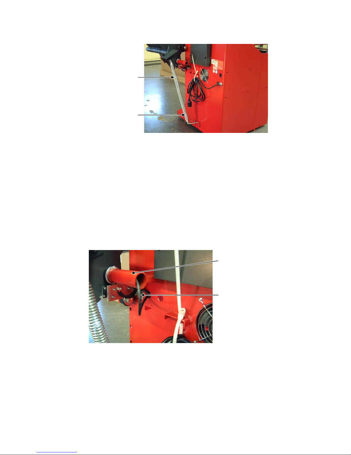
3. Verify that the hood is in the raised position and attach the spring to the stud found on the hood spring
attachment bracket.
HOOD SPRING,
98-303-2
HOOD SPRING HOOK,
216-43-2
Install Optional Outer Dataset® Arm (DSP9600 only):
1. Route the one wire attached to the Outer Dataset® Arm assembly, 103-131-1, through the hood shaft.
2. Using a 7/32 inch Allen wrench, remove the Allen screw from the black portion of the Outer Dataset® Arm.
3. Position the black portion of the Outer Dataset® Arm into the shaft.
4. Rotate the black bushing on the Outer Dataset® Arm until it aligns with the alignment hole in the shaft.
5. Reinstall the 3/8 inch SBHCS (Allen head) screw, 74-93-2, into the alignment hole and secure.
6. Verify that the wiring is taut through the hollow shaft.
7. Route the wire through the grommet in the rear of the machine.
HOLLOW SHAFT
WIRE FROM
DATASET® ARM
5
Page 6

8. Secure the wire assembly in the 6 o’clock position to the hood tube clamp with a cable tie, 94-35-2, making
sure that the cable has a two inch minimum loop as shown to allow for arm travel.
NOTE: DO NOT
OVER-TIGHTEN
THE CABLE TIE.
2”
9. Connect the wire with the double orange ty-raps to the J3 “OUTER DIST” address on the DSP board.
6
Page 7

10. Secure excess wires to the rear of the balancer by opening a plastic wire clamp and positioning the excess
wire inside.
PLASTIC WIRE
CLAMP
Install Storage Pegs:
1. Verify that the Keps nut, 76-159-2, is on the threaded surface of the storage peg. Verify that the serrated
surface of the Keps nut faces the balancer.
2. Thread the storage peg, 63-85-2, into a hole on the left-hand side of the balancer.
3. Position the peg so it is angled up and hold the peg in place while you secure the Keps nut with a 9/16 inch
wrench.
4. Repeat steps one through three for additional storage pegs.
CAUTION: Do not allow the pegs to protrude inside the balancer and contact the
balance frame structure.
BALANCER
FRAME
STORAGE PEG
THREADS
7
Page 8

Belt Break-In:
1. Remove four screws securing the spindle drive belt cover to the base assembly on the right side of the
DSP9600/9100.
SPINDLE DRIVE
BELT COVER
2. Check belt tension:
a.) Remove the weight tray from the balancer (if not done already).
b.) Position end of indicator flush with scale of belt tension tool.
c.) Place index finger inside rubber finger strap of belt tension tool.
d.) Position belt tension tool on horizontal section of belt between motor and spindle.
e.) Push down on belt tension tool until the tool clicks.
f.) Read belt tension tool where top edge of the arm crosses the scale (refer to illustration).
g.) Set belt tension to 90 lbs., ± 5 lbs. (41 kg., ± 2 kg.) Check 30 days after installation. Reset if
necessary.
8
Page 9

3. Adjust belt tension:
A
a.) Loosen four motor mount bolts.
b.) Position a 1/2 inch drive ratchet into the square hole in the adjusting cam.
c.) Increase belt tension by pulling the ratchet in a clockwise rotation.
d.) Tighten four motor mount bolts.
e.) Recheck belt tension and adjust as needed.
f.) Position spindle drive belt cover to housing assembly and secure using four screws
previously removed.
Install Weight Tray:
DJUSTING CAM
MOTOR MOUNT
BOLT
1. On DSP9600, remove hose from optional Inflation Station™ holder and drape over spindle shaft.
2. Slide the Inner Dataset® Arm out past the hub. Tilt the arm so that it catches on the hub. The hub will prevent
the arm from returning to the “home” position.
3. Place the weight tray on the DSP9600/9100 base assembly.
NOTE: When installing the weight tray, it may be necessary to lift up on the rear of
the weight tray, while pushing the weight tray backward into position.
4. Secure the weight anvil to weight tray with two socket head bolts previously removed.
5. Secure the weight tray to the base with the Phillips head screw previously removed from the weight tray’s
front left corner.
6. Place the Inner Dataset® Arm back into its home position.
7. Place the hose back into the Inflation Station™ holder, if so equipped.
8. Connect the electrical power cord to the AC power source.
Weight Tray Decal Installation:
Place the weight tray decals, 128-421-2, on the indentations above the weight tray pockets.
Verifying the Hub and Shaft Installation:
Using a dial indicator, measure hub face and shaft runout. Runout on the hub face should not exceed 0.0015
inch. Runout on the shaft should not exceed 0.0015 inch. If runout exceeds these limits, replace the hub/shaft
assembly.
9
Page 10

Switch Test
1. Connect electrical power cord to AC power source and air supply line to the air inlet (if necessary).
2. Turn the DSP9600/9100 Balancer “ON” while holding the Right and Left Split Weight buttons during power up
to enter “Diagnostic Mode.” Press the “Next” button to begin showing diagnostic variables.
3. Dial the “D” knob to diagnostic item number 36. Zero will be displayed on the right digits.
4. Press all buttons and close all switches. Each switch closure should be followed by a beep indicating that the
switch is functioning.
5. Dial the “D” knob clockwise to exit the switch test.
Verify Installation of Auto Dataset Arm(s) (DSP9600 only):
1. While in “Diagnostic Mode,” press “Next” to verify that the wire connection for the Inner and optional Outer
Dataset® Arms are correct:
a.) Dial the “D” knob to diagnostic item number 28. Move the Outer Dataset® Arm in a horizontal
line from right to left. The real-time numbers displayed on channel 28 on the screen should
increase.
b.) Dial the “D” knob to diagnostic item number 26. Move the Inner Dataset® Arm in a horizontal
line from left to right. The real-time numbers displayed on channel 26 on the screen should
decrease.
c.) Dial the “D” knob to diagnostic item number 27. Move the Inner Dataset® Arm in a vertical
line upward. The real-time numbers displayed on channel 27 on the screen should increase.
d.) If the numbers are not behaving as described above, the cable connections are reversed and
need to be exchanged.
2. Calibrate Auto Inner and Outer Dataset® Arms.
Auto Inner Dataset® Arm (DSP9600 only):
NOTE: Requires Calibration Tool, 221-672-1
1. Press “Setup/Cal” button once. “CAL” is displayed.
2. Press
equipped with outer Dataset® arm.
“Next” button. “CAL” is displayed at inner Dataset® arm location, and “---]” is displayed if
10
Page 11

3. Press
“Enter” to begin calibration. The step numbers are shown on the display, starting with “Stp -1-.”
Each step is described as follows:
NOTE: Turn the distance dimension knob to backup to a previous cal step.
a.) Verify that the inner arm is not extended, is in the “home” position, and is not moving.
Tap the foot pedal once or press “Enter.”
b.) Place the calibration tool on the shaft, using the spindle shaft slot located closest to the
middle of the calibration tool, as shown. Rotate the calibration tool slowly by hand,
clockwise until there is a beep, and the step number changes to “-3-.”
c.) Position the calibration tool parallel to the floor. Tap the foot pedal once or press “Enter.”
d.) Place the inner Dataset® arm at upward position “1” as shown. Tap the foot pedal once
or press “Enter.”
WHEN POSITIONING THE INNER DATASET ARM,
VERIFY THAT THE INDENT OF THE ARM IS
ON THE BUTTON FOR EACH POSITION.CENTERED
3
2
1
e.) Move the inner Dataset® arm to upward position “2.” Tap the foot pedal once or press
“Enter.”
f.) Move the inner Dataset® arm to upward position “3.” Tap the foot pedal once or press
“Enter.”
11
Page 12

g.) Place the inner Dataset® arm at downward position “4.” Tap the foot pedal once or press
“Enter.”
3
2
1
h.) Move the inner Dataset® arm to downward position “5.” Tap the foot pedal once or press
“Enter.”
i.) Move the inner Dataset® arm to downward position “6.” Tap the foot pedal once or press
“Enter.”
j.) Position the calibration tool parallel to the spindle shaft on the hub using the hub
mounting slot as shown.
7
8
9
k.) Place the inner Dataset® arm at the position “7.” Tap the foot pedal once or press
“Enter.”
l.) Move the inner Dataset® arm to position “8.” Tap the foot pedal once or press “Enter.”
m.) Move the inner Dataset® arm to position “9.” Tap the foot pedal once or press “Enter.”
If optional auto outer Dataset® arm is not installed, calibration is complete. If optional auto outer Dataset® arm is
installed, continue with Auto Outer Dataset® Arm Calibration.
12
Page 13

Optional Auto Outer Dataset® Arm (DSP9600 only):
NOTE: Requires Calibration Tool, 221-672-1
1. With the hood in the raised position, verify that the outer arm is in the “home” position and that the arm and
hood are not moving. Tap the foot pedal once or press “Enter.”
2. Place the calibration tool on the hub using the hub mounting slot as shown.
1
2
3
3. Place the outer Dataset® arm ball in hole position “1.” Tap the foot pedal once or press “Enter.”
4. Place the outer Dataset® arm ball in hole position “2.” Tap the foot pedal once or press “Enter.”
5. Place the outer Dataset® arm ball in hole position “3.” Tap the foot pedal once or press “Enter.”
6. Dataset® arm calibration is complete. “RDY” is displayed near the inner arm graphic to indicate that the inner
Dataset® calibration passed. “RDY --]” is displayed on the weight digits to indicate that the outer Dataset®
calibration passed.
Balancer Calibration:
1. Press the “Setup/Cal” button once. “CAL” is displayed.
2. Press the “Enter” button to begin calibration.
3. Do not install cal weight. Lower the hood and press “Start” to spin (if “Hood Autostart” is disabled).
4. Install cal weight on left side of hub faceplate in either hole, align cal weight at TDC, and press the “Enter”
button.
5. Spin.
6. Move cal weight to right side of hub faceplate in same hole.
7. Spin, display reads “CAL RDY.”
13
Page 14

A
8. Store the calibration weight in the threaded hole on the control panel support.
CONTROL PANEL
CALIBRATION
WEIGHT
CONTROL PANEL
SUPPORT
Install Optional Wheel Lift (DSP9600 only):
1. If “ON,” turn the DSP9600 Balancer “OFF.”
2. Disconnect the electrical power cord from the AC power source.
3. Disconnect air supply hose from the shop’s air supply line.
4. If present, remove tie wraps securing attachment blocks, 121-205-2, to lift mechanism arms.
LIFT MECHANIS M
ARMS
TTACHMENT
BLOCKS,
121-205-2
5. Remove packaging from beam, 118-649-1-002, and from hardware.
6. Beam must be rotated so that the top of the beam is toward the front of the balancer. After the mounting plate
is inside of the tub, the beam should be rotated 90 degrees clockwise.
TUB
MOUNTING
PLATE
TOP SIDE
OF BEAM
14
Page 15

NOTE: Orientation of the beam when slid into the balancer tub is very important.
If the beam is inserted into the balancer tub incorrectly, it cannot be rotated
into the proper position.
7. With the beam rotated so that the mounting plate is horizontal, secure the beam to the lift mechanism arms
with the four bolts and lock washers provided. Ensure that arms are fully seated against the attachment
blocks before tightening.
LIFT MECHANIS M
ARMS
TOP SIDE
OF BEAM
NOTE: The bolts should be finger-tightened only at this time.
8. Connect air supply hose to the shop’s 90-145 psi (6.21-10.00 bar) air supply line.
9. Connect the electrical power cord to the AC power source.
10. Turn the DSP9600 Balancer “ON.”
11. Move the lift control handle (located on the front of the DSP9600) upward to move the lift approximately
halfway up in its travel.
UP
DOWN
LIFT CONTROL
HANDLE
12. Remove the nut securing the trolley bolt to the beam, then remove the bolt. Refer to photo in step 14 for
location of trolley bolt and nut.
15
Page 16

A
13. With the trolley carriage toward the operator, slide the trolley onto the beam.
TROLLEY
CARRIAGE
14. Reinstall the trolley stop bolt previously removed through the beam and secure with the nut previously
removed.
GROOVED ROLLER
TROLLEY BOLT
FLAT ROLLER
NOTE: For the trolley stop bolt to work properly, it must be installed from the inside
of the beam and the nut located on the backside of the beam.
15. Roll an average size tire/wheel assembly onto the trolley.
16. Lift the lift control handle “up” to move the lifting beam and trolley into position to slide the tire/wheel assembly
onto the spindle. Verify that the tire/wheel assembly is centered vertically on the spindle.
TIRE/WHEEL
SSEMBLY CENTERED
VERTICALLY ON
SPINDLE
SPINDLE
17. Slide the beam forward or backward to center the tire/wheel assembly on the spindle horizontally.
18. When the tire/wheel assembly is centered vertically and horizontally, securely tighten the four bolts attaching
the mounting flange to the attachment blocks.
16
Page 17

NOTE: It may be necessary to remove the tire/wheel assembly from the trolley to
move the beam. However, the mounting position of the beam must be
verified with the tire/wheel assembly in place.
19. Lift the end of the beam slightly when tightening the bolts to close the gap between beam mounting plate and
the attachment blocks.
NOTE: Ensure that the four bolts securing the beam’s mounting plate to the
attachment blocks are completely tightened.
20. To verify proper operation of the wheel lift assembly, remove the tire/wheel assembly from the trolley, raise
the wheel lift, and then close the hood of the balancer. Lifting beam and trolley should lower automatically.
Install Operation Instruction Placard:
1. Flip the placard hanger, 117-193-1-002, forward.
2. Open a split ring, 223-74-2, and insert it through both small holes on the left side of the placard hanger. Slide
the left holes of the placard, 214-121-2, over the split ring, and then close the split ring. Verify that the hinge
of the split ring is located on the backside of the placard hanger.
3. Open a split ring and insert it through both small holes in the center of the placard hanger. Slide the center
holes of the placard over the split ring and then close the split ring. Verify that the hinge of the split ring is
located on the backside of the placard hanger.
4. Open a split ring and insert it through both small holes on the right side of the placard hanger. Slide the right
holes of the placard over the split ring and then close the split ring. Verify that the hinge of the split ring is
located on the backside of the placard hanger.
PLACARD HANGER,
117-193-1-002
SPLIT RING,
223-74-2
HINGE
PLACARD,
214-121-2
5. Return the placard to its storage position behind the display when not in use.
IN USE POSITION
17
STORAGE POSITION
 Loading...