

Page 1

Installation • Operation • Care
Palm Beach™ Polysatin™ Shutters
Page 2

CONTENTS
Getting Started
Installation Overview ..................................................... 1
Unpacking .................................................................... 1
Tools and Materials Needed ........................................... 1
Fasteners ..................................................................... 2
Frame Assembly
Assemble the Frame – Panel Systems ............................ 3
Assemble the Frame – Track Systems ............................ 7
Installation
Framed Standard Panel Systems .................................... 8
Standard Panel Systems with Hang Strip ...................... 11
Unframed Standard Panel Systems .............................. 13
Bi-Fold Track Systems ................................................. 15
Bypass Track Systems ................................................. 20
French Door Shutters .................................................. 29
Corner Windows.......................................................... 31
Bay Windows .............................................................. 33
Framed Stand-Alone Specialty Shapes ......................... 36
Framed Specialty Shapes Over Standard Shutter ........... 37
Unframed Specialty Shapes ......................................... 38
Decorative Sill Cover ................................................... 39
Finish Work ................................................................. 40
Operation and Care
Operation ................................................................... 43
Care ........................................................................... 43
Troubleshooting ........................................................ 44
If you have any questions about installation, application, operation,
or care and cleaning, Hunter Douglas Customer Service Shutter
Specialists are available at 1-888-727-5230 toll-free. Shutter
Specialists are available from 6:00 a.m. to 5:00 p.m. Mountain
Standard Time, Monday through Friday.
© 2016 Hunter Douglas. All rights reserved. All trademarks used herein are the property of Hunter Douglas
or their respective owners.
Page 3

GETTING STARTED
Hunter Douglas Palm Beach™ Polysatin™ shutters are built using the highest quality materials.
When properly installed, these shutters will provide a lifetime of beauty and performance.
IMPORTANT: These installation instructions are intended for professional installers who have
been certified after attending Hunter Douglas shutter training.
Installation Overview
Panel shutters come in many configurations — individually hinged, bi-fold panels, with and
without T-posts, track systems comprised of from one to many panels, and with a variety of
frames for inside or outside mounting.
Whatever the configuration, installation procedures are basically the same. The frame is
assembled and fastened to the window at two points. Then the shutter panels are individually
installed and racked, during which time frame attachment is completed. Duracatch
adjustment or magnet mounting, caulking and other finish work complete the installation.
™
lock
Unpacking
Carefully unpack the shutters. The package will include:
■ Shutter panels
■ Disassembled frames (frames for specialty shapes are typically assembled)
■ Miscellaneous hardware (hinge pins, button covers, etc.)
Tools and Materials Needed
Tools
■ Flat blade, Phillips, and Robertson #1 and #2screwdrivers
■ Power drill anddrill bits, including a 2" drill bit
■ Rubber mallet
■ Miscellaneous tools for non-typical installations (jig saw, hack saw, Dremmeltool,etc.)
Materials
■ Canvas drop cloth large enough for unpacking and frame assembly
■ Clean fabric cloth and a mild cleaning spray solution
■ Shim materials
■ Finishing supplies (caulk, sealant, etc.)
■ Instant adhesive for frame miters
■ Silcone adhesive or doubled-sided tape for Decorative Sill Cover installation
■ Measuring tape
■ Level
■ Awl
1
Page 4

GETTING STARTED
Fasteners
Screws of varying lengths and types are required to install shutters. The chart below shows the
standard fasteners, what each is used for, and the tool or driver needed to secure them. Other
types of fasteners may be needed if mounting into concrete, metal, or similar surfaces.
#8 x 3" Panel Assembly Screw
#8 x 2" Pan Head Screw
#8 x 2" Pan Head Screw
#8 x 1½" Pan Head Screw
#8 x 1" Pan Head Screw
#8 x ¾" Pan Head Screw
#8 x 2" Bugle Head Screw
#8 x ¾" Flat Head Screw
#6 x 1¾" Round Head Screw
Attaches stiles to rails; also used
as an installation screw
#2 Robertson drive
Installation screw
#1 Robertson drive
Attaches Bi-fold or Bypass bracket to wall
#2 Phillips drive
Installation screw
#1 Robertson drive
Attaches Bi-fold and Bypass carrier hardware to
panels
#2 Phillips drive
Attaches Bi-fold and Bypass track to frame or
opening, as well as track system brackets to frame
#2 Phillips drive
Attaches T-post to frame
#2 Phillips drive
Attaches Bi-fold pivot bracket to frame
#2 Phillips drive
Attaches T-post block to frame
#1 Robertson drive
#6 x ¾" Round Head Screw
#6 x ½" Pan Head Screw
#6 x 3/8" Pan Head Screw
#6 x 5/8" Flat Head Screw
#6 x 3/8" Flat Head Screw
2
Attaches magnets
#2 Phillips drive
Attaches Bi-fold bottom track pivot bracket to
bottom track
#2 Phillips drive
Attaches L-bracket to Bi-fold or Bypass frame and
valance
#2 Phillips drive
Attaches hinges to frames and T-posts, as well as
magnet strike plates to panels
#1 Robertson drive
Attaches metal corner key to frame
#1 Robertson drive
Page 5

Panel Systems
Bottom
FRAME ASSEMBLY
Assemble the Frame – Panel Systems
Prepare the work area. Lay the shutter panels on your drop cloth face up as they will appear in
the window. Then follow the procedure below.
1. Lay the side frames beside the panels, so that the panel hinges are above the frame hinges.
If one or more T-posts are used, lay them in the proper position, as well.
Top
Corner Key
Position hinge leaf
on frame below
hinge leaf on panel
Corner Key
2. Insert the plastic corner keys into the ends of the top and bottom frames.
➤ The Deluxe Casing frame, Colonial Z-frame, Classic Z-frame and Standard Z-frame
receive both the corner keys and metal brackets.
➤ Insert the side frame pieces onto the corner keys (and metal brackets, if applicable) of
the top frame.
IMPORTANT: With outside mount L-frames that have no T-posts, glue the corner keys in
position as described in Step 3 on the following page.
3
Page 6

FRAME ASSEMBLY
Panel Systems
3. Outside mount L-frames with no T-posts: Glue the corner keys in position as illustrated.
This prevents the frame from bowing.
➤ First remove the tabs off the corner key with a flat blade screwdriver.
➤ Then apply a small amount of instant adhesive or contact cement to the inside of
the frame.
➤ Insert the corner key into the end of the frame and hold firmly until set.
IMPORTANT: Be sure the frames match before gluing. The corners cannot be detached
after the adhesive has set.
Outside Mount L-Frame with No T-Posts Only
Apply
Tab
Adhesive
Inside
Frame
4. With the Deluxe Casing frame, Colonial
Z-frame, Classic Z-frame and Standard
Z-frame, secure the top frame metal
brackets to the side frames using the
provided screws.
4
Tabs
Removed
Page 7
Panel Systems
FRAME ASSEMBLY
5. Frames with T-posts: Attach the T-post to
the top frame.
➤ T-post blocks will be pre-attached to the
#8 x 2"
Bugle Head
Screw
top and bottom frame pieces.
➤ Slide the T-post onto the T-post block on
the top frame piece and secure the T-post
to the block using a #2 Phillips bit to drive
the provided bugle head screw.
IMPORTANT: A long driver bit is required to
get enough access to drive the screw.
T-Post Block
NOTE: See Step 8 on page 6 if T-post blocks
were not provided, or for three-sided frames
or inside mounts with no frames.
6. Attach the bottom frame to the side frames
and T-post, repeating the methods described
T-Post
in Steps 2 through 5.
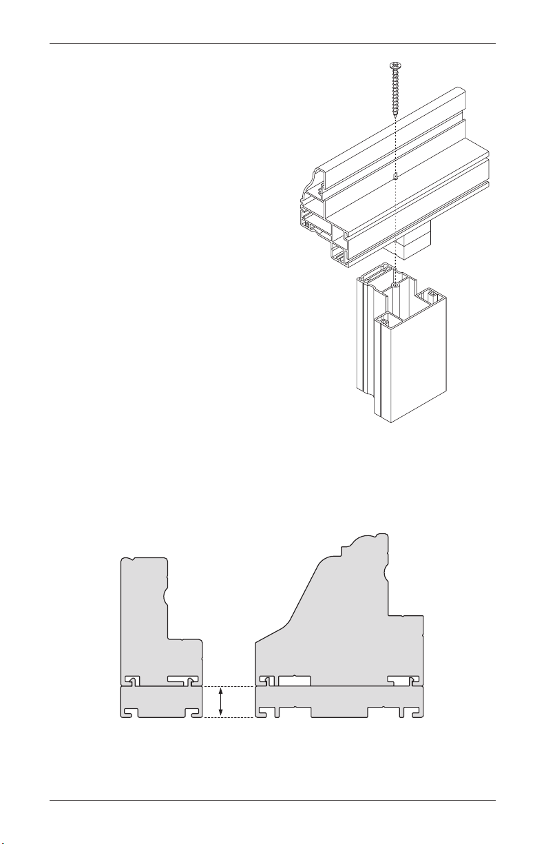
7. Deluxe Casing frame and outside mount L-frame only: If build-out is needed for
additional clearance, install the build-out onto the back of the frame.
➤ The build-out snaps onto the back of the frame.
➤ The Deluxe Casing frame build-out is also screwed into the back of the frame.
Top
Frame
L-Frame Build-Out
½"
Deluxe Casing Frame Build-Out
5
Page 8

FRAME ASSEMBLY
Panel Systems
8. With 3-sided frames or inside mounts with no frame, T-post brackets are used to attach
the T-post to the sill or casement after the frame has been installed. Refer to the illustration
below.
➤ Attach the brackets to the sill or casement using the slotted hole on the bracket to allow
for side-to-side adjustment.
➤ Be sure to square the T-post before tightening the brackets.
➤ T-post brackets can also be used to attach T-posts to frames when T-post blocks are
not provided.
IMPORTANT: When a Decorative Sill Cover is used, it must be placed between the window
sill and T-post before attaching the T-post.
T-Post
T-Post
Bracket
Sill
6
Page 9

Track Systems
¾"
Build-Out
FRAME ASSEMBLY
Assemble the Frame – Track Systems
Prepare the work area. Lay the frame pieces on your drop cloth in their proper orientation.
Thenfollow the procedures below.
1. Use four screws to attach the top frame to the side frames.
➤ With four-sided systems, attach the bottom frame to the side frames in the same way.
2. If build-out is needed for additional clearance, secure the build-out onto the back of the
frame with screws, as shown below.
3" Screws
Track System
(Bi-Fold Shown)
Build-Out
¾"
Pre-Drilled
Outside Mount
Installation
Screw Holes
Pre-Drilled
Inside Mount
Installation
Screw Holes
7
Page 10
INSTALLATION
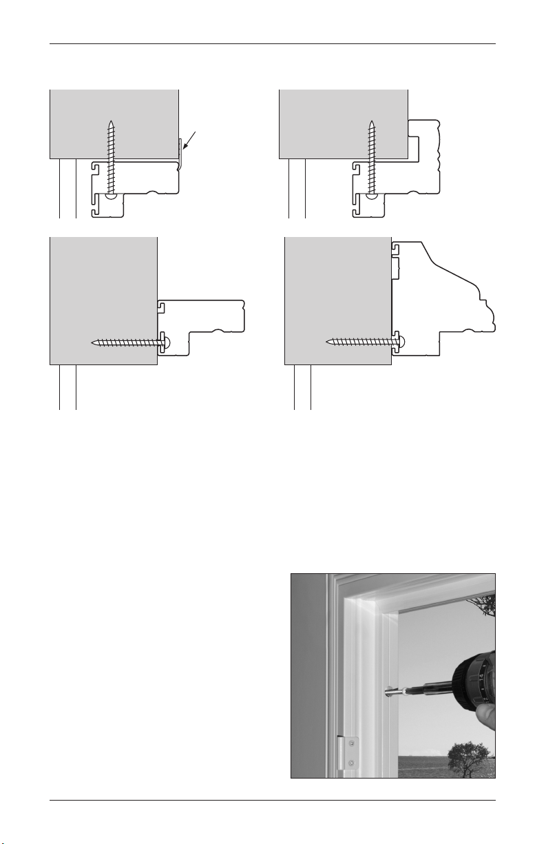
Framed Standard Panel Systems
Optional
Cover Strip
Standard
L-Frame
(IM)
Framed Standard Panel Systems
Standard
Z-Frame
(IM)
Standard L-Frame
(OM)
Deluxe Casing Frame
NOTE: If a Decorative Sill Cover was ordered, refer to page 39.
Step A. Install the Frame
1. Position the frame for mounting.
➤ Outside (OM) Mount. Center the frame over the opening. There should be a ¼" reveal
on all four sides (or an equal reveal if a larger or smaller reveal was specified on the
original order).
➤ Inside (IM) Mount. Center the frame
in the opening. Insert temporary shims
between the shutter frame and the
window to hold the frame centered.
2. Attach the side frames at the top corners
through the pre-drilled holes.
IMPORTANT: Tighten the screws snugly, but
do not overtighten.
(OM)
8
Page 11

Framed Standard Panel Systems
Step B. Mount the Panels
INSTALLATION
1. First, retract the Duracatch™ locks on the top
and bottom of the panels.
Duracatch Lock
➤ The Duracatch lock system is designed
to help level the panels within the frame.
Retracting the locks makes it possible to
rack the shutter.
➤ Using a flat blade screwdriver, push down
on the Duracatch lock and tighten the
screw a quarter-turn.
Recessed Lock
Push Down and
Tighten ¼ Turn
2. Align the panel and frame hinges, and insert the hinge pins.
3. Close the panels and check for proper alignment.
➤ If panels are misaligned, rack the shutter by grasping the frame at the bottom corners
and moving it from side to side until proper alignment is achieved.
NOTE: In the following procedures, after
each fastener is placed, close the panels
and check the alignment. If the alignment
is lost, remove the fastener, re-align the
panels, and then re-install thefastener.
IMPORTANT: For installations with multiple
T-posts, it is recommended that you begin
your racking at the center most section and
work your way out to each end.
Incorrect
Correct
9
Page 12

INSTALLATION
Framed Standard Panel Systems
4. Hold the frame in the aligned position.
➤ Outside (OM) Mount. Use a fastener to secure the center of the bottom frame. Check
alignment, and then secure the side frames at the bottom corners.
➤ Inside (IM) Mount. Use fasteners to
secure the side frames at the bottom
corners.
5. Insert screws into the remaining holes and check that the panels are still aligned after each
screw has been tightened. Re-adjust if necessary.
6. Release all Duracatch
™
panel lock assemblies by loosening the lock screws a quarter-turn.
7. Close the panels and, if needed, adjust the Duracatch locks with a flat blade screwdriver so
that all doors close easily yet stay firmly shut.
➤ If necessary, install panel lock ramps on the sill or casement (see page 40).
➤ If necessary, install magnets and plates (see page 41).
8. Perform any other necessary finish work to complete the installation (see page 42).
3
NOTE: If necessary to drill more installation holes in the frame, drill
/8" holes through the first
layer of vinyl only. Drill through the light block for both inside and outside mounts. (For sample
drilling locations, see the illustrations at the top of page 8.)
10
Page 13
Hang Strip Behind Panels
Hang Strip to Side of Panels
Standard Panel Systems with Hang Strip
Standard Panel Systems with Hang Strip
INSTALLATION
Hang Strip
Bent Leaf Hinge
3
/8" Holes for
Installation Screws
Hang Strip
Standard Hinge
3
/8" Holes for
Installation Screws
NOTE: If a Decorative Sill Cover was ordered, refer to page 39.
Step A. Install the Hang Strips
1. Attach the side hang strips inside or outside the opening.
➤ With outside mounts, be sure the hang strips are positioned the correct width apart and
at the correct height.
➤ Insert a Robertson screw into the top and bottom holes only, then set the screws into the
mounting surface.
➤ Tighten the screws snugly, but do not overtighten.
Step B. Mount the Panels
1. Hang the panels by fitting the pin end of the hinges into the hinge barrels.
2. Square and align the panels to the opening.
➤ Hang Strip Behind Panels. If
necessary, adjust the bent-leaf hinges
by loosening the hinge screws and
moving the hinge left or right.
➤ Hang Strip to Side of Panels. If
necessary, place hinge shims between
the hinge and hang strip.
➤ Re-tighten the hinge screws once the
panels are square and aligned.
Incorrect
Correct
11
Page 14

INSTALLATION
Standard Panel Systems with Hang Strip
3. Insert screws into the remaining holes and check that the panels are still level after each
screw has been tightened. Re-adjust if necessary.
4. With inside mounts, install Duracatch
™
panel lock ramps (see page 40).
5. With outside mounts, install magnets and plates (see page 41).
6. Perform any other necessary finish work to complete the installation (see page 42).
12
Page 15

Unframed Standard Panel Systems
INSTALLATION
Unframed Standard Panel Systems
Unframed inside-mounted shutters may be installed flush with the opening or projected out from
the opening using extended leaf hinges, which are
NOTE: If a Decorative Sill Cover was ordered, refer to page 39.
5
/8" wider.
Step A. Install the Bottom Leaf of the Top Hinge
1. Position the left panel in the opening so that it has equal clearance at the top and bottom.
Mark where the bottom of the top hinge is located.
2. Align the top of the bottom leaf with the mark and attach it using one screw.
3. To check for accurate placement, install the panel by its top hinge, inserting a hinge pin to
hold the panel in place. Adjust placement of the hinge, if necessary.
➤ If placement is accurate, remove the panel and install the second screw into the bottom
leaf of the top hinge.
Step B. Install the Bottom Leaf of the Bottom Hinge
1. With the panel placed in the top hinge, mark where the bottom of the bottom panel hinge is
located.
2. Align the top of the bottom leaf of the hinge with the mark and attach it using one screw.
3. To check for accurate placement, install the panel into the two hinges. Adjust placement of
the bottom hinge, if necessary.
➤ If placement is accurate, install the second screw into the bottom hinge.
4. Repeat steps A and B for the right panel, if applicable. Be sure to align the right panel to the
left panel.
Glass
Inside Mount
Flush with Opening
Top Leaf Attached
to Shutter
Bottom Leaf
Attaches to Opening
13
Page 16

INSTALLATION
Unframed Standard Panel Systems
Step C. Install the Remaining Bottom Leafs of the Hinges
1. Once the panels are level and square in the opening, install the remaining bottom leafs while
the panels are hanging.
➤ Open the panels and install the bottom leafs onto the top leafs using the hinge pins.
➤ Screw the bottom leafs in place.
➤ If necessary, shim using the provided hinge shims.
™
2. Install Duracatch
➤ When the Duracatch panel lock system is used, turn the adjustable plunger if minor
support or leveling is required.
3. Perform any other necessary finish work to complete the installation (see page 42).
panel lock ramps (see page 40) or magnets and plates (see page 41).
14
Page 17

Bi-Fold Track Systems
INSTALLATION
Bi-Fold Track Systems
Typically, bi-fold track systems have three-sided frames; however, they may also be two-sided
or four-sided. The basic installation procedure is the same whatever the configuration. (If you
haven’t already assembled the bi-fold frame, refer to page 7.)
Step A. Prepare the Frame
1. Installation screw holes are pre-drilled. If you
3
need additional attachment points, drill
/8"
holes in the frame through the first layer of
vinyl only.
➤ Drill through the screw indicator groove
on the light block for outside mounts and
through the side of the frame for inside
Screw
Indicator
Groove
mounts.
➤ With outside mounts (unless mounting
into the header), the top frame should be
mounted into studs wherever possible.
2. If an aluminum track is attached to the top frame, remove it before proceeding.
Step B. Install the Frame
IMPORTANT: Tighten the mounting screws snugly, but do not overtighten.
Inside Mount
1. Center the frame in the opening.
2. Using the provided screws, attach the top of the frame to the opening and level. Use shims
as needed to ensure a level installation.
3. Secure the pivot side frame, using a level to make sure the frame piece is plumb. Again, use
shims as needed.
➤ If there are two pivot sides (split stack), secure only one of the side frames.
Outside Mount
1. Center the frame over the opening at the
desired height.
2. Attach the top frame first, starting with one
fastener at the highest corner.
IMPORTANT: Install all mounting screws
into studs or the window header.
15
Page 18

INSTALLATION
Bi-Fold Track Systems
3. Place a four foot level on the top frame and secure the second fastener in the top frame at
the other corner, ensuring the top frame is level.
4. Finish attaching the top frame by securing
one screw at each stud, 16" to 24" apart,
depending on the type of construction.
➤ Space screws no more than 30" apart if
Pivot Side
Frame
mounting into the header.
5. Secure the pivot side frame, using a level to
make sure the frame piece is plumb. Again,
use shims as needed.
➤ If there are two pivot sides (split stack),
still secure only one of the side frames.
Step C. Attach the Aluminum Track to the Frame
1. Before attaching the track, make sure that you have inserted the correct number of carriers
and top pivot pins. For one way operation, one pivot pin and one snubber are required. For
split operation, two pivot pins are required, but no snubber.
Pivot Pin SnubberCarriers
IMPORTANT: Carriers have three wheels. Each
carrier can be loaded into the track with one
wheel to the front or two wheels to the front.
2. After inserting the carriers, check that the carrier
heights are the same as the pivot pin height, as
shown below. Adjust as necessary.
Pivot
Pin
Same Height
CORRECT
16
Different Height
INCORRECT
Page 19

Bi-Fold Track Systems
INSTALLATION
3. If the track arrived attached, use the same holes and re-attach the aluminum track to the top
frame with the screws supplied. Be sure the holes line up correctly.
➤ If the track did not arrive attached, use the screw indicator groove in the frame to align
the track screws.
Step D. Attach the Shutter Panels
1. Set the pivot pin(s) in the track so that the
5
center of the pivot pin is 1
/8" from the side
15/8"
Set Screw
frame.
2. Mount the bottom pivot bracket(s) or floor guide with bottom pivot(s).
IMPORTANT: The pivot pin receiver(s) must be directly under the top pivot pin(s). The center
of the pivot pin receiver(s) should be 1
5
/8" from the side frame(s).
➤ Bottom Pivot Bracket. Mount the bottom pivot bracket(s) centered on the screw
indicator groove in the side frame(s).
➤ Floor Guide with Bottom Pivot. Insert the bottom pivot(s) into the floor guide and
tighten the screws with the pivot pin receiver(s) in the correct position. Attach the floor
guide to the floor, centered on the screw indicator groove in the side frame(s).
Bottom
Pivot
Bracket
Floor Guide
with Bottom
Pivot
3. Mount the first panel per side into the bottom pivot pin receiver first and then onto the top
pivot pin. Rotate the lever on the receiver to lock the top pivot pin in place.
➤ When both sides have pivot pin receivers, install the first panel on the other side as well.
➤ If adjustment is necessary, mark the correct position of the top and/or bottom receiver(s)
to correctly re-position the component(s).
17
Page 20

INSTALLATION
Bi-Fold Track Systems
4. Insert the remaining shutter panels into the hinges and receivers.
➤ Using labels and hinges for correct panel positioning, lock all panels into place by
rotating the lever on the receiver.
➤ If panels are uneven make any minor adjustments with the carrier bolts.
Carrier Receiver
Step E. Finalize the Adjustment
1. For one-way operation: Secure the stile
channel.
➤ Attach the stile channel on the same side
as the snubber, approximately 3" from
the bottom of the frame, on the screw
indicator groove.
➤ Close the panels and locate the
unsecured frame so that the snubber
contacts the panel and the panel fits into
the stile channel. Secure the frame in
this position.
Stile
Channel
2. For two-way operation: Hold the loose side frame so the center split panels come
together. Then adjust the carriers, if necessary. Finally, mark the position of the side frame
and secure it.
18
Page 21

Bi-Fold Track Systems
INSTALLATION
Step F. Attach the Optional Valance
IMPORTANT: Two valances are available, standard (3½") and decorative (5"), and both are
mounted in a similar manner.
1. Attach the valance returns. Glue the miter joints and attach with L-brackets.
2. There should be approximately ¼" space between the bottom of the valance and the top
of the panels. A simple way to achieve this clearance is to place two stacked
shims onto the open panels in several places to support the valance during installation.
3. Standard valance: There are two options for installing the standard valance.
3
/8" installation holes through the first layer of vinyl only. Space the holes 20" apart
➤ Drill
and cover them with button plugs after securing the valance.
➤ Attach the valance with double-sided tape.
4. Decorative valance: Secure the valance with L-brackets, as
shown. Space the L-brackets every 20".
Step G. Complete the Installation
L-Bracket
■ Perform any necessary finish work to complete the
installation (see page 42).
1
/8" wood slat
Back of Valance
Adjustable
Screw Hole
Top of Frame
19
Page 22

INSTALLATION
Bypass Track Systems
Bypass Track Systems
Typically, bypass track systems have three-sided frames; however, they may also be two-sided
or four-sided. The basic installation procedure is the same whatever the configuration. (If you
haven’t already assembled the bypass frame, refer to page 7.)
If installing the bypass track system as an Inside Mount Without Frame, skip to Step C. After
installing the carriers, set the tracks with 2¼" between centers to allow 5/8" between tracks.
Step A. Prepare the Frame
1. Installation screw holes are pre-drilled. If you
3
need additional attachment points, drill
/8"
holes in the frame through the first layer of
vinyl only.
➤ Drill through the screw indicator groove
on the light block for outside mounts and
through the side of the frame for inside
Screw
Indicator
Groove
mounts.
➤ With outside mounts (unless mounting
into the header), the top frame should be
mounted into studs wherever possible.
2. If aluminum tracks are attached to the top frame, remove them before proceeding.
3. Outside mounts (OM) only: Attach support brackets to the top of the frame.
➤ Position the brackets where they will be mounted into studs. If stud spacing is 24",
attach support brackets to each stud. If stud spacing is 16", attach the brackets to every
other stud, so that they will be spaced 32" apart.
➤ Screw the brackets into the frame at the screw indicator grooves, with the back of the
bracket flush with the back of the frame.
➤ Use support bracket extensions with Open Bypass and Triple Track systems, or if Bypass
frame extension (build-out) is attached to the frame when greater projection or louver
clearance is needed.
Support
Bracket
Support Bracket
Extension
Support Bracket
Extension
Build-Out
Bypass Frame Bypass Frame with
Frame Extension (Build-Out)
Open Louver/Triple Track Frame
IMPORTANT: Be careful not to place support bracket screws where they will interfere with
the track screws.
20
Page 23

Bypass Track Systems
INSTALLATION
Step B. Install the Frame
IMPORTANT: Tighten the mounting screws snugly, but do not overtighten.
Inside Mount
1. Center the frame in the opening.
2. Using the provided screws, attach the top of the frame to the opening and level. Use shims
as needed to ensure a level installation.
Outside Mount
1. Center the frame over the opening at the
desired height.
2. Attach the top frame first, starting with one
fastener at the highest corner.
IMPORTANT: Install all mounting screws
into studs or the window header.
3. Place a four foot level on the top frame and
secure the second fastener in the top frame
at the other corner, ensuring the top frame
is level.
4. Finish attaching the top frame by securing one screw at each stud, 16" to 24" apart,
depending on the type of construction.
➤ Space screws no more than 30" apart if mounting into the header.
Step C. Attach the Tracks to the Frame
1. Before attaching the tracks, make sure that you have inserted the correct number of carriers
(two carriers for each panel) into the appropriate track.
2. Prior to inserting the carriers, check that the carrier heights are consistent from carrier to
carrier (see photos below). Adjust as necessary.
Different Heights
INCORRECT
Same Height
CORRECT
21
Page 24

INSTALLATION
Bypass Track Systems
3. If the tracks arrived attached, use the same holes and re-attach the aluminum tracks to the
top frame with the screws supplied. Be sure the holes line up correctly. If the tracks did not
arrive attached:
➤ Standard Bypass and Open Bypass: Center the tracks over the screw indicator
grooves and secure with screws through the pre-drilled holes in the tracks.
➤ Triple Track Systems: Install the tracks in the screw ports indicated in the illustration
below.
Step D. Prepare the Shutter Panels
IMPORTANT: If optional floor guides will be used, refer to Step G on page 25 before proceeding.
Two of the three floor guide options require mounting components to the bottom of the shutter
panels before they are hung from the carriers. In addition, privacy strips are included with the
floor guide options that should be installed on the front panels before hanging them.
1. Double panels only: If panels are designed to be operated in pairs, marry the pairs
together.
➤ Lay the pair of panels next to each other on a flat surface, with the front side up.
➤ At the top of the panels, remove the stile caps from the abutting stiles.
➤ Insert the panel couplers.
Panel
Coupler
Remove
Stile Caps
Slide in
Coupler
Sections
NOTE: The panels must lie flat to allow the couplers to slide into the stiles.
■ Place the stile caps back onto the stiles.
22
Page 25

Bypass Track Systems
INSTALLATION
2. If optional floor guides will be used: Mount any required components to the bottom of
the shutter panels.
3. If optional floor guides will be used: Attach privacy strips.
➤ Remove the liner from the adhesive on the privacy strips.
➤ Position the privacy strips on the panels as needed for the opening (see bottom
illustrations).
➤ Press each privacy strip firmly against the stile. Be sure to apply pressure at several
places along the full length of the privacy strips.
Front
Panel
Standard Bypass (Top View)
Rear Panel
Triple Track (Top View)
Rear Panel
Open Bypass (Top View)
Rear Panel
Privacy Strip
Middle Panel
Back
Panel
Privacy Strip
Front Panel
Clearance not required
for U-channel track
and floor guide only.
Privacy Strips
Front Panel
Privacy Strips
Front Panel
23
Page 26

INSTALLATION
Bypass Track Systems
Step E. Mount the Shutter Panels
1. Mount the panels onto the carriers and lock them in place by rotating the lever on the
receiver. Continue until all panels are secure.
2. Check that floor clearance is acceptable. If not, lower or raise panels by adjusting both
carrier bolts the same amount.
Carrier Receiver
Step F. Check for Alignment
1. If necessary, adjust the carrier bolts so that all panels are at the same height.
2. Open the louvers of the back panel where panels overlap and slide the front panel until the
stile is adjacent to or touching the open louvers. If gaps appear between the front panel stile
and the open louvers at the top or bottom, adjust the carrier bolts until no gaps appears.
INCORRECT CORRECT
Gaps
No
Gaps
3. Finalize alignment by locating the side frames to their adjacent panel and secure to the wall
with fasteners.
24
Page 27

Bypass Track Systems
Floor Guides
INSTALLATION
Step G. Install Optional Floor Guides
Floor guides prevent the shutter panels from swinging forward into the room or backward into
the opening. There are three floor guide options for bypass track systems.
Option 1: U-Channel Track and Floor Guide
Front
Panel
Privacy Strip
U-Channels
Back
Panel
1. Before mounting the shutter panels: Center the U-Channel on the bottom of each panel
and attach it using screws or double-sided tape.
2. After mounting the shutter panels:
Attach one or more floor guides to the floor
with screws.
➤ Align the bottom tracks with the score
lines on the frame, as shown at right.
3. After attaching the floor guide(s), align the
U-Channel into the guide(s), as shown in
the illustration above.
NOTE: A
5
/8" height deduction is taken at
the factory to ensure proper clearance.
Triple Track shown
25
Page 28

INSTALLATION
Option 2: Three-Piece Bypass Floor Guide
Bypass Track Systems
Front
Panel
Privacy Strip
Three-Piece Floor Guide
Back
Panel
1. After mounting the shutter panels: Attach one or more center pieces of the floor guides
to the floor. Refer to the diagram below for placement.
Floor Guide Attachment – Top View
PANEL 1L PANEL 1L
One Guide Two Guides Three Guides
PANEL 1CPANEL 1R
PANEL 1R PANEL 1L
PANEL 1C PANEL 1C
PANEL 1R
➤ Align the center piece of the guide directly under the shutter panel overlap.
➤ Position the center piece(s) so that each panel will always be over at least one of them.
➤ Set the center piece(s) in place with a screw.
2. After attaching the center piece(s), slide the two smaller side pieces in place.
➤ Adjust for the overall width from the front and back panels.
➤ Set the center piece(s) in place with a screw.
NOTE: A ½" height deduction is taken at the factory to ensure proper clearance.
26
Page 29

Bypass Track Systems
Option 3: Hidden Panel Bypass Guides (U-Guide and L-Guide)
INSTALLATION
Panel
1
/8"
U-Guide L-Guide
Privacy StripFront
Back
Panel
3
/8"
1. Before mounting the shutter panels: Attach the U-Guides and L-Guides to the bottom of
the shutter panels using screws or double-sided tape.
➤ These hidden guides eliminate the need to attach anything to the floor.
➤ Attach the U-Guide(s) to the bottom of the front panel(s) as illustrated above. Position
1
the front of the U-Guide
/8" from the front of the stile or flush with the front edge of the
bottom rail.
➤ Attach the L-Guides to the bottom of the back panel(s). Position the rear of the L-Guide
3
/8" from the back of the of the stile or ¼" from the back edge of the bottom rail.
2. When mounting the shutter panels: Mount the back panel(s) first, then fit the U-Guide
over the L-Guide when mounting the front panels.
NOTE: A ½" height deduction is taken at the factory to ensure proper clearance.
27
Page 30

INSTALLATION
Bypass Track Systems
Step H. Attach the Optional Valance
1. Attach the valance returns. Glue the miter joints and attach the returns with L-brackets.
2. Position the valance so that it covers the hardware and attach it to the top frame.
3. Standard valance: There are two options for installing the standard valance.
3
/8" installation holes through the first layer of vinyl only. Space the holes 20" apart
➤ Drill
and cover them with button plugs after securing the valance.
➤ Attach the valance with double-sided tape.
4. Decorative valance: Secure the valance with L-brackets,
as shown. Space the L-brackets every 20".
Step I. Complete the Installation
■ Perform any necessary finish work to complete the
installation (see page 42).
Back of Valance
Adjustable
Screw Hole
L-Bracket
Top of Frame
28
Page 31

French Door Shutters
INSTALLATION
French Door Shutters
French door shutters are mounted using the L-frame, either 3-sided or 4-sided. Installation
procedures for French door cut-outs are the same as those for full panel French door shutters.
(If you haven’t already assembled the French door frame, refer to page 3.)
French Door Shutter
with 4-Sided Frame
(FD)
French Door Shutter
with 3-Sided Frame
(FD)
French Door Cut-Out
with 4-Sided Frame
(FDC)
French Door Cut-Out
with 3-Sided Frame
(FDC)
Step A. Install the Frame
1. Center the frame over the opening. Handle three-sided frames very carefully to avoid
placing stress on the corner joints. Be sure the corner keys have been glued into position
as described on page 4.
➤ Check that the overlap (if any) is the same in the middle, top, and bottom. This will
assure that the vertical line of the door will match the vertical line of the shutter.
➤ Four-sided frames: Secure the side frame next to the knob. Place the first screw by
the door knob, second screw near the top, and third screw near the bottom.
➤ Three-sided frames: Secure the hinged side frame. Place the first screw in the top
installation hole, second screw near the bottom, and third screw in the center.
➤ Tighten the screws snugly, but do not overtighten.
IMPORTANT: Angle the screws to avoid breaking the glass.
IMPORTANT: With French door cut-outs, make sure the cut-out
is centered on the door knob.
2. Most frames have pre-drilled holes for ease of installation. If
additional installation holes are needed, drill
3
/8" holes in the
frame through the first layer of vinyl only.
L-Frame
Angle
Screw
Glass
29
Page 32

INSTALLATION
French Door Shutters
Step B. Mount the Panels
1. If the shutter uses the Duracatch™ lock system, first retract the Duracatch locks on the top
and bottom of the panels. Refer to the procedures in Step 1 on page 9.
2. Place the panel into the frame by fitting the pin end of the hinges into the hinge barrels.
IMPORTANT: Carefully support the frame while inserting the panel into the hinges. Use
supports under the hinged side of the frame to support the weight of the panel.
Step C. Racking and Securing
Four-Sided Frames
1. Close the panel and check for proper alignment.
➤ If panels are misaligned, grasp the hinged side of the frame and rack up and down until
proper alignment is achieved.
➤ Open the panel and insert a screw above the top hinge in the pre-drilled hole.
➤ Close the panel and check alignment. If misaligned, remove the screw and re-align.
➤ If proper alignment is maintained, proceed to step two.
2. Secure the bottom of the side frame through the pre-drilledholes.
3. Close the panel and adjust the center of the hinged side frame so that the gap between the
other side frame and the panel is consistent. Mark the proper position of the frame, open the
panel, and attach the frame through the pre-drilled hole.
4. Attach all remaining fasteners.
IMPORTANT: With each fastener that is placed, close the panel and check the alignment. If
the alignment is lost, remove the fastener, re-align the panel, and re-install the fastener.
Three-Sided Frames
1. Close the panel. Check that the vertical line of the door matches the vertical line of the
shutter panel and frame. Loosen and adjust the frame or hinge attachment, as necessary.
2. Align the top and bottom frames with the shutter panel and secure their ends.
3. Attach all remaining fasteners.
All frames
1. Release all Duracatch panel lock assemblies by loosening the lock screws a quarter-turn.
2. Close the panels and, if needed, adjust the Duracatch locks with a flat blade screwdriver so
that all doors close easily yet stay firmly shut.
3. If necessary, install magnets and plates (see page 41).
4. Perform any other necessary finish work to complete the installation (see page 42).
30
Page 33

Corner Windows
INSTALLATION
Corner Windows
Corner window shutters are two framed shutters connected together at a 90-degree angle.
Before performing a corner window installation, you should be familiar with the framed shutter
installation procedures described on pages 8–10. (If you haven’t already assembled the shutter
frames, refer to page 3.)
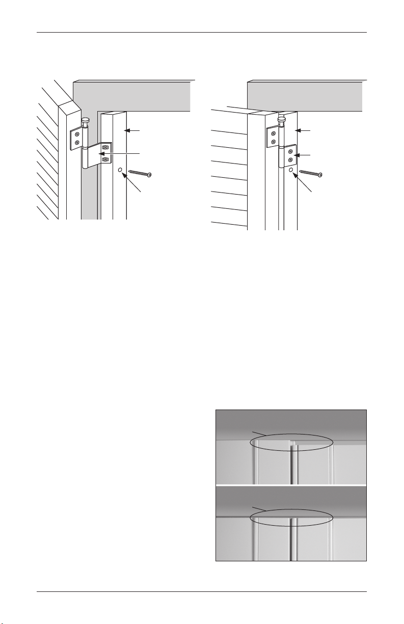
Step A. Connect the Two Assembled Frames
1. Position the provided hang strip flush with the front of the right side of the left frame. Attach
it with screws through the frame, on the screw indicator line.
2. Attach the left side of the right frame to the hang strip in a similar fashion.
Hidden Hang Strip Joins Corner L-Frames
Hang Strip
Step B. Install Frames (Inside or Outside Mount)
1. Center the attached frames (L-frame and Z/L-frame combinations) over or into the openings
and even out your reveal.
2. Secure the top and bottom inside corners of the left and right frame.
Step C. Mount the Left Corner Panel(s)
1. First, retract the Duracatch™ locks on the top and bottom of the panels. Refer to the
procedures in Step 1 on page 9.
2. Support the left side of the frame with support blocks (OM) or shims (IM) before inserting
the panel(s).
3. Place the panel(s) into the left frame by fitting the pin end of the hinges into the hinge
barrels.
31
Page 34

INSTALLATION
Corner Windows
Step D. Rack and Secure the Left Corner Panel(s)
1. After mounting the panel(s), close the panel(s) and check for proper alignment.
➤ If misaligned, grasp the left side of the
left frame at the top and bottom and
move the frame up and down until proper
alignment is achieved.
➤ Mark the position of the frame on the wall
and open the panel.
2. Attach the bottom of the frame through the
pre-drilled holes. Be sure the frame lines up
with your mark.
3. Close the panel(s) and check alignment.
4. Secure the balance of the frame. There should be one screw within 3" of each corner and no
more than 30" between fasteners.
IMPORTANT: With each fastener that is placed, close the panels and check the alignment. If the
alignment is lost, go back to the fastener, remove, re-align, and re-install.
Mark
Position
Step E. Mount the Right Corner Panel(s)
■ Repeat Step C for the right panel(s).
Step F. Rack and Secure the Right Corner Panel(s)
■ Repeat Step D for the right panel(s).
Step G. Complete the Installation
1. Release all Duracatch™ panel lock assemblies by loosening the lock screws a quarter-turn.
2. Close the panels and, if needed, adjust the Duracatch locks with a flat blade screwdriver so
that all doors close easily yet stay firmly shut.
3. If necessary, install magnets and striker plates (see page 41).
4. Perform any other necessary finish work to complete the installation (see page 42).
32
Page 35

Bay Windows
INSTALLATION
Bay Windows
If you haven’t already assembled the bay window shutter frames, refer to page 3.
Step A. Install the Middle Bay Frame (Inside or Outside Mount)
1. Center the frame of the middle bay over (OM) or into (IM) the opening.
2. Attach the top frame at the top corners with Robertson screws through the pre-drilled holes.
Tighten snugly, but do not overtighten.
Outside
Mount
Inside
Mount
Step B. Mount the Middle Bay Panel(s)
1. First, retract the Duracatch™ locks on the top and bottom of all panels. Refer to the
procedures in Step 1 on page 9.
2. Place the panel(s) into the middle bay frame by fitting the pin end of the hinges into the
hinge barrels.
Step C. Rack and Secure the Middle Bay Panel(s)
1. After mounting the panel(s), close the panel(s) and check for proper alignment.
➤ If misaligned, grasp the bottom frame and move it side-to-side until proper alignment is
achieved.
➤ Mark the position of the frame on the wall and open the panel(s).
Incorrect
Correct
Mark
Position
33
Page 36

INSTALLATION
2. Attach the frame at the bottom corners, making sure the frame lines up with your mark.
3. Close the panel(s) and check alignment.
4. Secure the balance of the frame. There should be one screw within 3" of each corner and no
more than 30" between fasteners.
IMPORTANT: With each fastener that is placed, close the panels and check the alignment. If the
alignment is lost, go back to the fastener, remove, re-align, and re-install.
Bay Windows
Step D. Install the Left Bay Frame
1. Align the right side of the left bay with the left side of the middle bay frame.
IMPORTANT: Make sure that the tops are flush, and the bead edge of the butting L-frames
are aligned properly and do not overlap.
2. Attach the top and bottom of the frame within 3" of the right corners.
Step E. Mount the Left Bay Panel(s)
1. Support the left side of the frame with support blocks (OM) or shims (IM) before inserting
the panel(s).
2. Place the panel(s) into the left frame by fitting the pin end of the hinges into the hinge
barrels.
Step F. Rack and Secure the Left Bay Panel(s)
1. After mounting the panel(s), close the panel(s) and check for proper alignment.
➤ If misaligned, grasp the left side of the left frame at the top and bottom and move the
frame up and down until proper alignment is achieved.
➤ If necessary, mark the position of the frame on the wall and open the panel.
2. Attach the frame at the left-side top and bottom corners, making sure the frame lines up
with your mark.
3. Close the panel(s) and check alignment.
4. Secure the balance of the frame. There should be one screw within 3" of each corner and no
more than 30" between fasteners.
IMPORTANT: With each fastener that is placed, close the panels and check the alignment. If the
alignment is lost, go back to the fastener, remove, re-align, and re-install.
Step G. Install the Right Bay Frame
■ Repeat Step D for the right frame.
34
Page 37

Bay Windows
INSTALLATION
Step H. Mount the Right Bay Panel(s)
■ Repeat Step E for the right panel(s).
Step I. Rack and Secure the Right Bay Panel(s)
■ Repeat Step F for the right panel(s).
Step J. Complete the Installation
1. Release all Duracatch™ panel lock assemblies by loosening the lock screws a quarter-turn.
2. Close the panels and, if needed, adjust the Duracatch locks with a flat blade screwdriver so
that all doors close easily yet stay firmly shut.
3. If necessary, install magnets and striker plates (see page 41).
4. Perform any other necessary finish work to complete the installation (see page 42).
35
Page 38

INSTALLATION
Framed Stand-Alone Specialty Shapes
Framed Stand-Alone Specialty Shapes
NOTE: If a Decorative Sill Cover was ordered, refer to page 39.
Stand-alone specialty shape shutters are installed independently of standard shutters.
1. Place the frame in or over the opening and center. Make sure the bottom frame is level.
2. Attach the frame with two screws through the curved portion of the frame.
➤ Screws should be placed in the top left and top right of the curve as illustrated below.
➤ Do not overtighten the screws — doing so could distort the shape.
First Two Screw Locations
3. Place the panel into the frame by lining up the hinge barrels and inserting the hinge pins.
Close the top and sides by depressing the specialty shape’s Duracatch
™
spring-loaded
plungers into the grooves in the frame.
4. Move the bottom of the frame left or right to create the proper gaps around the panel.
➤ Mark the bottom frame location where the proper gaps are created.
➤ Remove the panel from the frame.
5. Move the bottom frame to align it with the mark, and screw through the middle of the bottom
frame to hold it in the correct position.
6. Place the panel back into the frame and double-check that it fits properly.
7. Remove the panel from the frame and set all remaining screws, being careful not to
overtighten.
8. Place the panel into the frame. Adjust plunger depth if necessary to provide a good fit in
the frame.
➤ If fit is too tight, push in on the plunger and rotate clockwise to recess the plunger.
➤ If fit is too loose, push in and rotate the plunger counterclockwise to extend it.
9. Perform any necessary finish work to complete the installation (see page 42).
36
Page 39

Framed Specialty Shapes Over Standard Shutter
INSTALLATION
Framed Specialty Shapes Over Standard Shutter
When a specialty shape is over a standard shutter, the bottom of the shape’s frame is attached
to the top of the standard shutter’s frame. The standard shutter is always installed before the
specialty shape.
NOTE: If a Decorative Sill Cover was ordered, refer to page 39.
1. Place the frame in or over the opening.
Align the bottom frame of the shape with
the top frame of the standard shutter.
2. Set two installation screws through the
bottom frame of the shape into the top
frame of the standard shutter. Do not
overtighten the screws.
3. Place the shaped panel into the frame
by lining up the hinge barrels and
inserting the hinge pins. Spring-loaded
plungers on the shape snap into
grooves on the frame.
4. Move the top of the shaped panel’s
frame left or right to create the proper
gaps around the shape.
➤ Mark the top frame location where
the proper gaps are created.
➤ Remove the shaped panel from
the frame.
5. Move the top of the frame to align it
with the mark, and screw through the
top center to hold the frame in the
correct position.
6. Place the shaped panel back into the frame and double-check that it fits properly.
7. Remove the shaped panel from the frame and set all remaining screws; do not overtighten.
8. Place the shaped panel into the frame. Adjust plunger depth if necessary to provide a good
fit in theframe.
➤ If fit is too tight, push in on the plunger and rotate clockwise to recess the plunger.
➤ If fit is too loose, push in and rotate the plunger counterclockwise to extend it.
9. Perform any necessary finish work to complete the installation (see page 42).
Attach Shape Frame
37
Page 40

INSTALLATION
Unframed Specialty Shapes
Unframed Specialty Shapes
Unframed specialty shape shutters are always inside mounted and attached with magnets.
NOTE: If a Decorative Sill Cover was ordered, refer to page 39.
1. Place the shaped panel in the opening and center it.
2. Mark the position of the left and right edges of the shape on the bottom of the opening.
3. Measure in from each mark ½", and make another mark. The second marks indicate where
the outside edges of the magnets will be installed.
½"
Left Edge
4. At the second set of marks, measure and
3
/8" back from the front edge of the
mark 1
opening. The front of the magnet will be
of Shape
Measure in ½"
Shutter Panel
GlassSpecialty Shape
Striker
Plate
located here.
➤ Measure for magnet position at the top
center of the shape in the same way.
➤ If more than three magnets are
3
1
/8"
Magnet
provided, space them evenly in the
opening.
5. Attach all magnets to the opening using the supplied magnet screws.
6. Attach striker plates to the shape so that they will align with the magnets when the shaped
panel is installed.
7. Install the unframed specialty shape panel and center from side to side.
➤ Check that each magnet makes good contact with the striker plates.
➤ Make any necessary adjustments to magnets that do not hold securely.
8. Perform any necessary finish work to complete the installation (see page 42).
38
Page 41

Decorative Sill Cover
"
Sill Cover with
Sill Cover with
INSTALLATION
Decorative Sill Cover
For details about the Decorative Sill Cover, see the Palm Beach section of the Hunter Douglas
Reference Guide.
1. Dry fit the Decorative Sill Cover before installing. Minor adjustments may be required.
2. For standard applications, the rear of the Decorative Sill Cover is flush with the back of the
shutter frame.
3. Attach the Decorative Sill Cover. The following products may be used to secure it: silicone
adhesive, caulk, double-sided tape, or screws that are concealed by the shutter frame.
Select the one that is best for your installation.
4. If provided, attach light stop to the Decorative Sill Cover.
5. Outside mount applications may require a filler strip that should be attached to the inside
bottom lip of the Decorative Sill Cover to fill the space between the sill cover and the wall.
6. For outside mount applications without an existing sill, attach a section of filler strip to the
wall to provide a support or mounting surface for the Decorative Sill Cover.
Inside Mount Frames
Window Sill
Wall
Wall
½"
7
/8"
Projection
(or Ear)
Sill Cover with
No Sill
¾" x 1"
Filler Strip
Used as
Mounting
Strip
Outside Mount Frames
Window Sill
Wall
Filler Strip
½"
Projection
(or Ear)
7
/8
Filler Strip
39
Page 42

INSTALLATION
Spring-
Loaded
Plunger
Sill
Finish Work
Finish Work
Install Duracatch™ Panel Lock Ramp(s), If Applicable
™
The Duracatch
frames during fabrication. If your panel configuration is a 3-sided frame application, install panel
lock ramps on the bottom sill. If a 2-sided frame, install the panel lock ramps on both the top
and bottom sills.
Panel Lock System with spring-loaded plunger is installed on panels and
Panel Lock Ramps
2-Sided Frame3-Sided Frame
Panel Lock Ramps
Panel Lock Ramps
1. With the shutter panel(s) closed, make a pencil
mark on the sill to show where the center of
each spring-loaded plunger is located.
2. Mark where to drill pilot holes for the screws.
➤ Open the shutter panel(s). Place the panel
lock ramp on the sill with the sloped edge
facing front. The front edge of the ramp
should be
1
/8" behind the front edge of
the panel.
➤ Center the panel lock ramp on the line
marking the plunger location.
Mark centerline of each plunger with pencil
➤ Mark the center of the ramp’s screw
holes. Repeat for all panel lock ramps.
3. Drill pilot holes for each panel lock ramp
3
/32" drill bit.
using a
4. Attach the panel lock ramps to the sill using the Robertson screws provided.
5. Close the shutter panels to check function and closure.
6. The spring-loaded plungers can be adjusted using a flat blade screwdriver.
➤ If closure is too tight, push in on the plunger and rotate clockwise to recess the plunger.
➤ If closure is too loose, push in and rotate the plunger counterclockwise to extend it.
➤ Rotate the plunger in one-half turn increments to maintain alignment with the stile cap.
SpringLoaded
Plunger
Sill
Panel Lock Ramp
1
/8"
40
Page 43

4-Sided Frame
Individually-Hinged Panels
3-Sided Frame
Bi-Fold Panels
e
Bottom
Finish Work
INSTALLATION
Install Magnets and Plates, If Applicable
If the shutter panels do not have panel locks, you may need to install magnets and plates if they
are not already installed.
1. Review the diagrams below. Plates are installed at the top and bottom of all shutter panels.
Magnets are installed behind the plates to the frame or sill.
Plate
Rear
View
Flush with
Bottom of Rail
3
/8"
2. Using a pencil, mark the frame (top and bottom)
where the stile meets the top and bottom rails,
on the side where the shutter closes against the
frame.
➤ With three-sided frames, mark the sill at the
bottom.
3. Install the magnets to the frame’s light block
so that the magnets are
3
/8" in from the mark,
toward the center of the shutter panel.
➤ With three-sided frames, install the magnet
3
to the sill
/8" in from the mark. Align the
magnet with the frame’s light block.
4. Install the plates on the rear of the panels so
that they align with the magnets. The corner of
the plates should be 3/8" in from the stile and the
edge of the top or bottom rail.
➤ With three-sided frames, install the bottom
plates flush with the edge of the bottom rail.
5. Close the shutter panels to check function and
closure. Adjust magnet or plate position, if
necessary.
3
/8"
Side
View
3
/8"
Plate
Flush
with
of Rail
Sill
Frame
Magnet on Fram
Plate
Top Rail
4-Sided
Frame
Bottom Rail
3-Sided
Frame
Bottom Rail
Plate
Magnet on Sill
41
Page 44

INSTALLATION
Finish Work
Touch-Up and Inspection
1. If you have not done so already, cap all screw holes with the provided button plugs. For easy
installation, first insert the button plug foot with the tab on it, and then slide the remaining
feet into the installation hole.
2. If you have not done so already, on inside-mounted L-frame applications glue L-frame cover
strips to the front of the L-frame to fill gaps between the frame and window jamb.
3. Apply sealant as needed to fill gaps between frames and window jambs or between mitered
corners.
4. Wash any dirt or grease from the shutter using a clean cloth and mild detergent solution.
Never use ammonia-based products.
5. Invite the home owner to inspect the installation. Give the home owner the Hunter Douglas
warranty card and explain the added protection provided by the Palm Beach
™
Promise,
which covers shutter panel and frame
members against warping, cracking,
fading, chipping, peeling, or discoloration.
Demonstrate proper operation of the shutters
and show the customer the location of their
individual authenticity plate serial number.
42
Page 45

OPERATION AND CARE
Operation
■ Tilt the louvers by grasping one louver and moving it.
■ Open the shutter panel by grasping the stile through open louvers and pulling out. Do not
use the tilt bar to open the shutter panel.
IMPORTANT: To open the panels on a bi-fold track system, collapse the first set of panels at the
pivot side followed by each successive set of panels until all panels are collapsed.
IMPORTANT: When using floor guides with a bypass track system, use caution when operating
panels to avoid panel damage where the guides contact the stiles.
Care
■ Clean using a dry and soft feather duster, clean cloth, dust cloth or dusting mitt. A vacuum
with the soft brush attachment can also be used.
™
■ Palm Beach
ammonia-based products.
■ Ultrasonic cleaning or use of chemical solvents and scrubbing cleansers are not
recommended. This will damage the product.
■ Palm Beach Polysatin shutters may accumulate static buildup during the shipping and
installation process. Static can attract dust or smoke residue from candles or fireplaces. To
reduce static cling and help repel dust, wipe the product with a soft, clean towel moistened
with mild soap and water or a fabric dryer sheet. Never use ammonia-based products or
abrasive cleaners as they may scratch or damage the surface.
Polysatin™ shutters may be washed using a mild detergent solution. Never use
43
Page 46

TROUBLESHOOTING
Problem: Panels Won’t Stay Closed
■ Check the Duracatch™ panel lock. Check to ensure that the panel lock plunger is seated
properly in the panel lock ramp. Possible problems include:
➤ The panel lock plunger is too far inside the panel. Adjust the plunger as described in
step 6 on page 40.
➤ The plunger does not sit in the “dip” in the panel lock ramp. Reposition the ramp, if
necessary. Refer to steps 1 through 5 on page 40.
➤ Check plunger and stile cap alignment. The plunger is designed to lock into grooves on
the stile cap to prevent unwanted rotation. If they are not aligned, the plunger will remain
inside the cap. To adjust, use a flat blade screwdriver to rotate the plunger until it is
properly aligned and able to extend beyond the stile cap.
■ Check the number of magnets. If magnets are used for closure, check that there are two
per panel, one at the top and one at the bottom. Refer to the magnet installation section on
page 41. (Note: Café style shutters use only one magnet.)
■ Check magnet contact. If magnets are used for closure, check that the magnets and
magnet plates have full contact with each other. Possible problems include:
➤ The magnet and plate are not aligned. The magnet or magnet plate may need to be
moved to achieve proper alignment. Refer to the magnet installation section on page 41.
➤ The magnet is at a slight angle, with only one side of the magnet touching the plate.
Loosen one of the screws on the magnet to allow it to be straightened so that it makes
full contact with the plate.
➤ The magnet plate is not flush with the panel, so that only one side touches the magnet.
Adjust the screws so that the magnet plate becomes flush with the panel.
■ Check panel load. Load is created when the installation is not square. This places load
on the stile, which can force the panel to open with a spring-back effect. If the load is
excessive, the louvers may be difficult to close, as well. Possible solutions include:
➤ If load is detected with framed applications, tighten or loosen the installation screws on
the frame. (Do not use shims.) Start by removing all the installation screws except for the
top. Re-install the bottom installation screw until there is no load. Continue with all other
installation screws, one at a time, checking for load after each one.
➤ If there is load on a bi-fold panel, remove the second bi-fold panel and resolve the
problem with the first hinged panel as described above. Then re-attach the second panel
and check that the problem has been resolved.
➤ If load is detected with unframed applications, shim the hinges to square the panels.
Remove all hinge pins except for the top and bottom. Shim those hinges as needed until
the problem is resolved. Continue with the other hinges, one at a time, checking for load
after each one.
44
Page 47

TROUBLESHOOTING
Problem: Panels Won’t Stay Closed (continued)
■ Check for obstructions that prevent panels from closing. Possible problems include:
➤ Window cranks can prevent panels from closing. Take the crank off the rotator and
see if the panel is still obstructed. If the panel closes, replacing the window crank with
a T-crank can often solve the problem. Otherwise, build-out may be required to add
clearance. For panels without a frame, an extension hinge may be used to bring the
panel into the room an extra
➤ Window locks are other possible obstructions. Add clearance as described above.
➤ Patio door handles can prevent louvers from opening. If a handle stops a panel from
closing, the shutter must be built-out.
➤ Bowed sills or casements can prevent inside-mounted shutter panels from closing if the
narrowest height and width measurements were not ordered. Double-check the inside
measurements and compare them with the measurements ordered and received.
■ Check for a twisted panel. Panel stiles can sometimes be twisted by weight leaned
against it or by extreme heat. Fortunately, the polysatin material can be “tweaked” back
to its original shape with gentle force. To do this, use your hand to support the middle of
the panel’s outside stile and bend the top or bottom back into position until the panel
remains closed.
5
/8".
Problem: Panels Are Too Tight
■ Check that the frame is installed properly. If the frame is not installed correctly, it may
cause the inside opening of the frame to be too narrow at a specific point, causing the
panels to be too tight. To check if the installation screws have been tightened the correct
amount, measure the top or bottom frame width and compare it to the width where the
panel appears to be too tight. Adjust the installation screws to square the frame.
■ Check that the panel is in the correct opening. When multiple windows are of similar
size, panels can sometimes be placed into the wrong opening or with the incorrect panel
grouping. Check the labels and order form instructions to ensure that the panels are in the
correct opening and with the correct panel group.
■ Classic Z-frame with rubber flex: remove the rubber flex from one side of the
frame. If the opening is smaller than expected and installation screws do not pull the frame
straight, it may be necessary to remove the rubber flex from the back of one or more sides
of the frame. This can be done easily and safely by making a small cut into the rubber flex
material at one end of the frame, then peeling the rubber flex off the frame.
45
Page 48

TROUBLESHOOTING
Problem: Louvers Are Not Working Properly
■ Check panel load. Review the procedures at the bottom of page 44.
■ Check connectors. With Palmetto
➤ Duralink
™
cufflink connectors attach the louvers to the tilt bar at the front of the panel.
Check that the connectors are securely attached. Snap them back into place if they are
detached.
IMPORTANT: To ensure the long life of shutters, the front tilt bar should not be used to
open the panel.
➤ With rear tilt bars, rear connectors attach the louvers to the tilt bar at the back of the
panel. Check that the connectors are securely attached.
■ Replace Duralink cufflink connectors (front tilt). Follow this procedure:
1. Pull the tilt bar from the louvers.
2. Remove the broken connector(s).
3. Replace the broken connector(s). Snap the new connector(s) into the hole on the
tilt bar.
4. Replace the tilt bar. Insert the connectors into the louvers by holding the louvers in
place and firmly pressing the connector into the notch on the louver.
™
shutters, connectors attach the louvers to the tilt bar.
46
Cufflink
Connector
Page 49

TROUBLESHOOTING
■ Replace rear tilt bar connectors. Follow this procedure:
1. Remove the broken connector(s).
2. Snap the new connector(s) into the rear tilt bar.
3. After all the broken connectors have been replaced, connect the tilt bar to the louvers by
snapping the connectors back onto the ends of the louvers.
Rear Tilt Bar
Connector
Problem: Shutter Is Discoloring
■ Check for residue build-up. The polysatin material has UV stabilizers to prevent
discoloring. Any situation of discoloration is a direct result of residue from a cleaner or
natural build-up (smoke, dust or oil furnace). Clean the shutter with soap and water. Never
use ammonia-based products.
Problem: Shutter Is Scratched
■ Remove scratches. Scotch-Brite™ 7448 light gray hand pads can be used to remove
minor scratches. Gently rub the Scotch-Brite pad over the scratch in the direction of the
extrusion. Apply minimal pressure when rubbing to avoid dulling the finish. Using very light
pressure, carefully blend the repair area into the surrounding material. The entire piece may
need to be treated.
■ Remove deeper scratches. If a scratch cannot be removed using Scotch-Brite, a more
aggressive approach may be required. Start with 1200 grit wet or dry sandpaper first, and
then finish with the Scotch-Brite 7448 pad to blend.
47
Page 50

NOTES
Page 51

Page 52

The Hunter Douglas® Lifetime Guarantee is an expression of our desire to provide a thoroughly satisfying
experience when selecting, purchasing and living with your window fashion produc ts. If you are not thoroughly
satisfied, simply contact Hunter Douglas at (888) 501-8364 or visit hunterdouglas.com. In support of this policy
of consumer satisfaction, we offer our Lifetime Limited Warranty as described below.
COVERED
BY A LIFETIME LIMITED WA RRANTY
• Hunter Douglas window fashion products are
covered for defects in materials, workmanship
or failure to operate for as long as the original
retail purchaser owns the product (unless shorter
periods are provided below).
• All internal mechanisms.
• Components and brackets.
• Fabric delamination.
• Operational cords for a full 7 years from the
date of purchase.
• Repairs and/or replacements will be made with
like or similar parts or products.
• Hunter Douglas motorization components are
covered for 5 years from the date of purchase.
• Palm Beach
™
fading, chipping, peeling and discoloring.
Promise covers warping, cracking,
• Any conditions caused by normal wear and tear.
• Abuse, accidents, misuse or alterations to the
• Exposure to the elements (sun damage, wind,
• Failure to follow our in
• Shipping charges, cost of removal and reinstallation.
NOT COVERED
BY A LIFETIME LIMITED WA RRANTY
product.
water/moisture) and discoloration or fading
over time.
to measurement, proper installation, cleaning
or maintenance.
structions with respect
Hunter Douglas (or its licensed fabricator/distributor) will repair or replace the
window fashion product or components found to be defective.
TO OBTA IN WARRANTY SERV ICE
1. Contact your original dealer (place of purchase) for warranty assistance.
2. Visit hunterdouglas.com for additional warranty information, frequently asked questions and access to service locations.
3. Contact Hunter Douglas at (888) 501-8364 for technical support, certain parts free of charge, for assistance in obtaining
warranty service or for further explanation of our warranty.
NOTE: In no event shall Hunter Douglas or its licensed fabricators/distributors be liable or responsible for incidental
or consequential damages or for any other indirect damage, loss, cost or expense. Some states do not allow the exclusion or
limitation of incidental or consequential damages, so the above exclusion or limitation may not apply to you. This warranty
gives you specific legal rights, and you may also have other rights which vary from state to state.
Different warranty periods and terms apply for commercial products and applications.
9930011018 4/16
 Loading...