

Page 1

A2C-WIFI
INSTALLATION GUIDE
Internal WiFi Module for ACC2
INSTALLATION
Turn controller power o before installing the module.
Remove the controller facepack to expose the communication
slot on the bottom. It is not necessary to disconnect
the facepack cable. Remove the dust cover from the
communication slot. Insert the Wi-Fi module completely
into the slot, pins rst, until the lock clicks into place.
Connect the antenna cable to the gold threaded connection
on the module. Install the antenna holder into one of the
smaller conduit openings in the bottom of the controller, so
that the antenna is fully exposed below the metal box. Firmly
hand tighten the nut on the inside of the controller to secure it.
Route the antenna cable from the module to the holder, so that
it has adequate slack to open the door, and will not be pinched
when closing the door. Insert the antenna into the holder.
Do not allow the metal connectors in any part of the antenna
cable to contact metal or earth ground when powered. This
will permanently damage the Wi-Fi module.
Restore power to the controller. If it is necessary to remove
the module aer installation:
• Turn controller power o.
• Press the spring-loaded locking lever on the module.
• Pull straight down to remove it.
Use the dial to go to Settings, Networking. Verify the
address of the controller by viewing Network Info screen.
Press so key for Wi-Fi Setup. Check the box for Direct
Connect. (The Central Setup function is not currently
active.) Open mobile device settings for Wi-Fi and search
for HunterACC-xxxx (where –xxxx is the unique four
digit number shown at Network Info), and connect.
Open browser.
Enter 192.168.1.3 (also shown on the Networking screen).
In a moment, the login screen should appear.
If there are no entries in the controller’s User Management
table, the user ID is “hunter” (lowercase). The PIN is “0000.”
If the User Management table has entries (Settings, User
Management), the user ID and PIN must match a valid
user ID and PIN in the User Management table.
If User Management is enabled, the user ID and PIN
must match a valid user ID and PIN in the controller’s
User Management menu.
The ACC2 page will appear in a few seconds aer a valid login.
CONTROLS
The Home button will return to the top level menu when
you have selected Start, Stop, Text Entry, or Flow.
There is a contrast button in the top right corner of the display
that will switch between light and dark backgrounds for day or
night situations.
STAR T
Select Start to operate any of the following immediately:
• Station
• Block
• Program
• PMV
Select the item, specify the run time, and press the
Star t button.
Page 2
RC00 4IG A2C WIFI 2/17
http:// hunter.direct/acc2help
RESIDENTIAL & COMMERCIAL IRRIGATION
|
Bu ilt on Innovation
®
Learn more. Visit hunterindust ries.com
STOP
The Stop command can be used to:
• Stop All Stations (this will stop everything in the controller).
• Stop all manually started stations (allows automatic
irrigation to continue).
• Stop a selected program (select the program, and
press Stop Program).
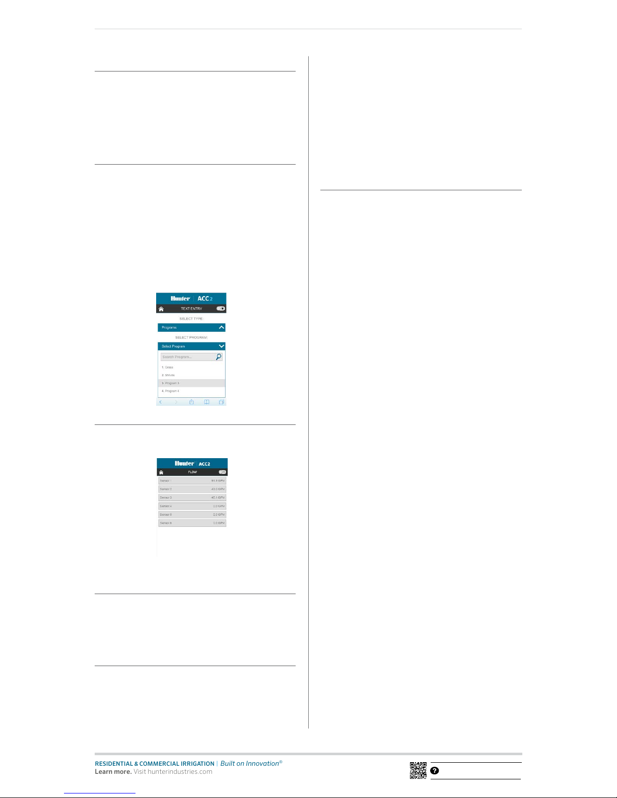
TEXT ENTRY
The mobile device can be used to enter names for:
• Stations
• Blocks
• Programs
• Water Sources (MainSafe zones)
• Flow Zones
• Clik Sensors
Names help with organizing large irrigation systems, and the
mobile device is easier to use for text entry than the interface
on the controller. Click the red “X” to completely erase the
default name (such as “Station 1”), or simply modify the name
that appears. Click Save to enter the name in the controller.
FLOW
The mobile device can view live ow rate information on all ow
sensors. There are no additional func tions on the ow screen.
UPDATING THE WI-FI MODULE
Wi-Fi modules can be updated from the SD card. Wi-Fi modules
can be updated from the SD card in the facepack, as part of the
normal rmware update process. The current version number
can always be found on the Diagnostics, Module Info screen.
TROUBLESHOOTING
Antennas must be placed outside a metal controller cabinet
to be eective. Use the antenna holder or conduit adapter to
locate the antenna outside the controller enclosure.
ACC2 controllers appear as HunterACC-xxxx in mobile device
settings screens. Make sure you are logged into the controller,
and not onto another network.
If multiple ACC2 controllers are within range, verify the
address of the one you want by viewing the Settings,
Networking, Network Info screen. The serial for the
controller will be shown on this screen.
If a module does not appear to be responding and network
settings are correct, check the Diagnostics menu, Module Info
screen to be sure the module is alive and seen by the controller.
If the module is shown as Not Present, turn the power o.
Remove, inspect, and re-seat the module, and test again.
REGULATORY AND LEGAL INFORMATION
This equipment has been tested and found to comply
with the limits for a Class B digital device, pursuant to
part 15 of the FCC rules. These limits are designed to
provide reasonable protection against harmful interference
in a residential installation. This equipment generates, uses
and can radiate radio frequency energy, and if not installed
and used in accordance with the instructions, may cause
harmful interference to radio communications. However,
there is no guarantee that interference will not occur in a
particular installation.
If this equipment does cause harmful inter ference to radio or
television reception, which can be determined by turning the
equipment o and on, the user is encouraged to tr y to correct
the interference by one or more of the following measures:
• Reorient or relocate the receiving antenna.
• Increase the separation between the equipment and
the receiver.
• Connect the equipment into an outlet on a circuit
dierent from that to which the receiver is connected.
• Consult the dealer or an experienced radio/TV
technician for help.
The user is cautioned that changes/modications not
approved by the responsible party could void the user’s
authority to operate the equipment. To satisfy FCC RF
Exposure requirements for mobile and base station
transmission devices, a separation distance of 20 cm or more
should be maintained between the antenna of this device and
persons during operation. To ensure compliance, operation at
a closer distance is not recommended. The antenna(s) used
for this transmitter must not be co-located or operating in
conjunction with any other antenna or transmitter. Under
Industry Canada regulations, this radio transmitter may only
operate using an antenna of a type and maximum (or lesser)
gain approved for the transmitter by Industr y Canada. To
reduce potential radio interference to other users, the
antenna type and its gain should be chosen so that the
equivalent isotropically radiated power (e.i.r.p.) is not more
than that necessary for successful communication.
Conformément à la réglementation d’Industrie Canada, le
présent émetteur radio peut fonc tionner avec une antenne
d’un type et d’un gain maximal (ou inférieur) approuvé pour
l’émetteur par Industrie Canada. Dans le but de réduire les
risques de brouillage radioélectrique à l’intention des autres
utilisateurs, il faut choisir le type d’antenne et son gain de
sorte que la puissance isotrope rayonnée équivalente (p.i.r.e.)
ne dépasse pas l’intensité nécessaire à l’établissement d’une
communication satisfaisante.
• Cet émetteur radio (IC : 7693A-24WG0MAMB) a été
approuvé par Industrie Canada pour fonctionner avec
les types d’antennes énumérés ci-dessous avec le gain
maximal admissible et l’impédance d’antenne requise pour
chaque type d’antenne indiqué. Les types d’antennes ne
gurant pas dans cette liste, ayant un gain supérieur au gain
maximum indiqué pour ce type, sont strictement interdits
pour une utilisation avec cet appareil.
 Loading...