

Humminbird XAP 9, XAP 9 20 User Manual
5
6
1
Inside the Hull Mounted Transducer
1-Year limited Warranty
We warrant the original retail purchaser that products made by
Humminbird® have been manufactured free from defects in materials
and workmanship. This warranty is effective for one year from the date
of original retail purchase. Humminbird® products found to be defective
and covered by this warranty will be replaced or repaired free of charge
at Humminbird® option and returned to the customer freight prepaid.
Humminbird® sole responsibility under this warranty is limited to the
repair or replacement of a product that has been deemed defective by
Humminbird®. Humminbird® is not responsible for charges connected
with the removal of such product or reinstallation of replaced or
repaired parts.
This warranty does not apply to a product that has been:
• Improperly installed;
• Used in an installation other than that recommended in the product
installation and operation instructions;
• Damaged or has failed because of an accident or abnormal
operation;
• Repaired or modified by entities other than Humminbird®.
Please retain your original receipt as a proof of the purchase date. This
will be required for in-warranty service.
THIS WARRANTY IS EXPRESSLY IN LIEU OF ANY OTHER WARRANTIES,
OBLIGATIONS OR LIABILITIES ON THE PART OF HUMMINBIRD® AND
WILL BE THE CUSTOMER'S EXCLUSIVE REMEDY, EXCEPT FOR ANY
APPLICABLE IMPLIED WARRANTIES UNDER STATE LAW WHICH ARE
HEREBY LIMITED IN DURATION TO ONE YEAR FROM THE DATE OF
ORIGINAL PURCHASE. IN NO EVENT WILL HUMMINBIRD® BE LIABLE
FOR ANY INCIDENTAL OR CONSEQUENTIAL DAMAGES FOR BREACH
OF ANY EXPRESS OR IMPLIED WARRANTY RELATING TO THE
PRODUCTS.
Some states do not allow limitations on an implied warranty, or the
exclusion of incidental or consequential damages, so the above
exclusions may not apply to you. You may also have other rights, which
vary from state to state.
530509-4_C
Humminbird® Service Policy
Even though you'll probably never need to take advantage of our
incredible service policy, it's good to know that we back our products
this confidently. We do it because you deserve the best. We will make
every effort to repair your unit within three business days from the
receipt of your unit at our factory. This does not include shipping time
to and from our factory. Units received on Friday are typically shipped
by the following Wednesday, units received Monday are typically
shipped by Thursday, etc.
All repair work is performed by factory-trained technicians to meet
exacting factory specifications. Factory-serviced units go through the
same rigorous testing and quality control inspections as new
production units.
After the original warranty period, a standard flat rate service charge
will be assessed for each repair (physical damage and missing parts
are not included). Any repairs made after the original warranty will be
warranted for an additional 90 days after service has been performed
by our factory technicians. You can contact our Customer Resource
Center or visit our website to verify the flat rate repair fee for your
product (visit the Product Support section):
http://www.humminbird.com
We reserve the right to deem any product unserviceable when
replacement parts are no longer available or impossible to obtain. This
Service Policy is valid in the United States only. This applies only to
Humminbird® products returned to our factory in Eufaula, Alabama.
This Service Policy is subject to change without notice.
DOMESTIC (USA) CUSTOMERS:
PLEASE DO NOT RETURN THIS PRODUCT TO STORE FOR SERVICE
For all technical issues please call 1-800-633-1468
Or visit www.humminbird.com, click SUPPORT
Please reference product serial number and
model number when contacting Humminbird®.
Inside the Hull Mounted Transducer
Returning Your Unit for Service
Before sending your unit in for repair, please contact the factory, either
by phone or by email, to obtain a Repair Authorization Number for
your unit.
NOTE: Please do not return your Humminbird® to the store for service.
Please have your product model name and serial number available
before calling the factory. If you contact the factory by e-mail, please
include your product model name and serial number in the e-mail, and
use Request for Repair Authorization Number for your e-mail subject
header. You should include your Repair Authorization Number in all
subsequent communications about your unit.
For IN-WARRANTY service, complete the following steps:
• Obtain a Repair Authorization Number from the Humminbird®
Customer Resource Center.
• Tag product with your name, street address, phone number and
your assigned Repair Authorization Number.
• Include a brief written description of the problem.
• Include a copy of your receipt (to show proof and date of
purchase).
• Return product freight prepaid to Humminbird®, using an insured
carrier with delivery confirmation.
For OUT-OF-WARRANTY service, complete the following steps:
• Obtain a Repair Authorization Number from the Humminbird®
Customer Resource Center.
• Include payment in the form of credit card number and expiration
date, money order or personal check. Please do not send cash.
• Tag product with your name, street address, phone number and
your assigned Repair Authorization Number.
• Include a brief written description of the problem.
• Return product freight prepaid to Humminbird®, using an insured
carrier with delivery confirmation.
Contact Humminbird®
Contact the Humminbird® Customer Resource Center
in any of the following ways:
By Telephone
(Monday - Friday 8:00 a.m. to 4:30 p.m. Central Standard Time):
1-800-633-1468
By e-mail
(typically we respond to your e-mail within three business days):
cservice@johnsonoutdoors.com
For direct shipping, our address is:
Humminbird
Service Department
678 Humminbird Lane
Eufaula, AL 36027 USA
WARNING! Do not touch an active transducer during operation, as this
may cause physical discomfort and may result in personal injury in the
form of tissue damage. Handle the transducer only when the power to
the control head is off.
WARNING! This device should not be used as a navigational aid to
prevent collision, grounding, boat damage, or personal injury. When the
boat is moving, water depth may change too quickly to allow time for you
to react. Always operate the boat at very slow speeds if you suspect
shallow water or submerged objects.
WARNING! Disassembly and repair of this electronic unit should
only be performed by authorized service personnel. Any modification
of the serial number or attempt to repair the original equipment or
accessories by unauthorized individuals will void the warranty.
Handling and/or opening this unit may result in exposure to lead, in
the form of solder.
WARNING! This product contains lead, a chemical known to the
st ate of Califo rnia to caus e ca ncer, birth defects and other
reproductive harm.
The WEEE Directive aims to minimize the impact of end-of-life
electrical and electronic equipment on human health and the
environment. Therefore, any product bearing the WEEE
symbol must not be included with unsorted municipal waste.
Instead, it must be separately collected, treated and recycled.
For proper disposal of this equipment, please contact the Johnson
Outdoors distributor or see www.humminbird.com.
530509-4_C
Inside the Hull Mounted Transducer
Thank You
Thank you for choosing Humminbird®, America's #1 name in fishfinders. Humminbird® has built its
reputation by designing and manufacturing top-quality, thoroughly reliable marine equipment. Genuine
Humminbird® accessories offer the opportunity to upgrade and expand the capabilities of your
Humminbird® product.
NOTE: Your transducer may not look exactly like the transducer shown in the illustrations, but it will mount
in exactly the same way.
Your Humminbird® is designed for trouble-free use in even the harshest marine environment. In the
unlikely event that your Humminbird® does require repairs, we offer an exclusive Service Policy - free of
charge during the first year after purchase, and available at a reasonable rate after the one-year period.
For complete details, see the Warranty section included in this manual.
Contact our Customer Resource Center at either 1-800-633-1468 or visit our website at
www.humminbird.com.
Installation Overview
Following are instructions for the installation of this accessory. Before you start installation, we encourage
you to read these instructions carefully in order to get the full benefit from your Humminbird® accessory.
If you find that any items are missing from your installation kit, call our Customer Resource Center at
1-800-633-1468 or visit our website at www.humminbird.com.
Installation
There are a number of ways to install a transducer on your boat. Inside the hull mounting of the
transducer generally produces good results in single thickness fiberglass hulled boats. Humminbird®
cannot guarantee depth performance when transmitting and receiving through the hull of the boat, since
some signal loss will occur. The amount of loss depends on hull construction and thickness, and the
installation.
NOTE: This type of installation requires the use of a slow-cure two-part epoxy. Do not use silicone or any
other soft adhesive material to install the transducer, as this material will reduce the sensitivity of the unit.
Do not use five-minute epoxy, as it has a tendency to cure before all the air bubbles can be purged, thus
reducing signal strength.
1.
Locating the Transducer Mounting Position
Decide where to install the transducer on the inside of the hull, using the following procedure to find the
best location:
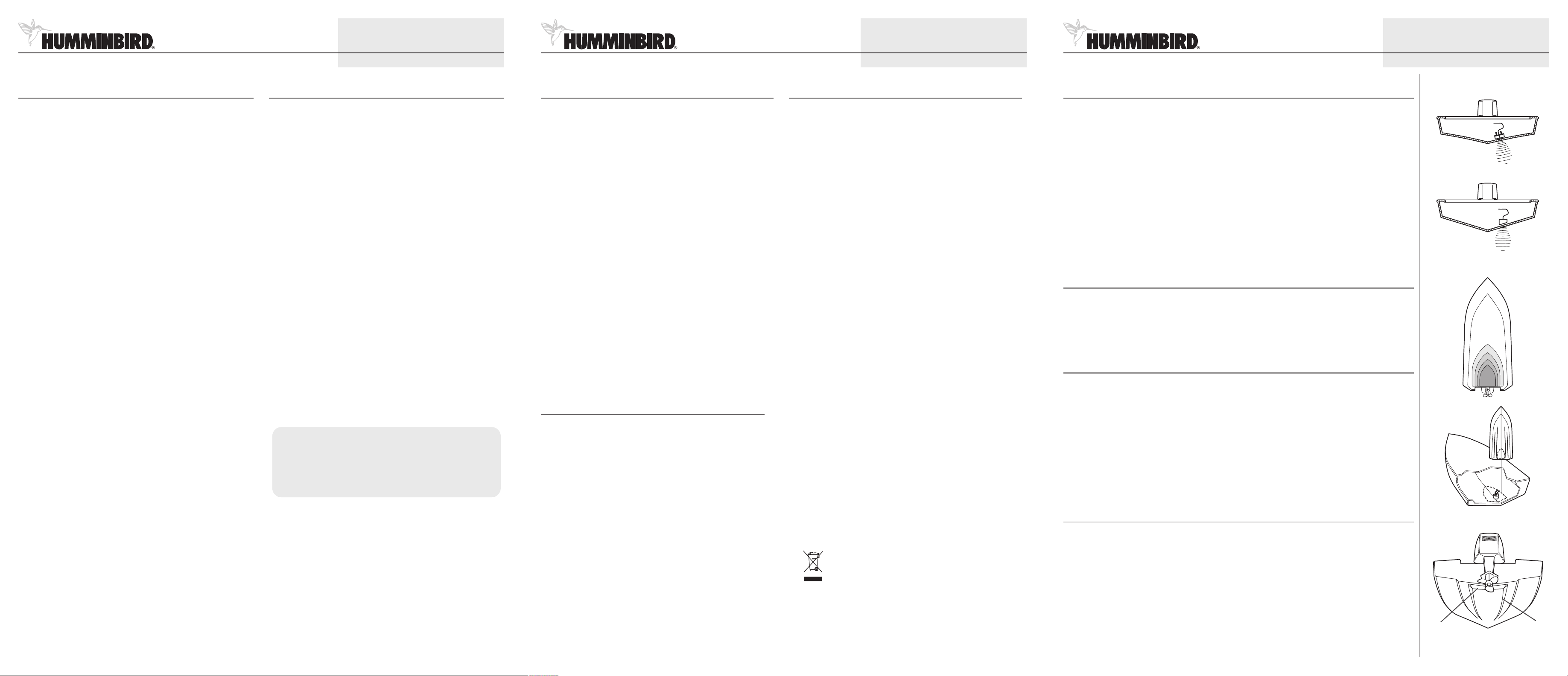
1. Observe the outside of the boat hull to find the areas that are mostly free from turbulent water. Avoid
ribs, strakes and other protrusions, as these create turbulence.
2. Make sure that the transducer is located as close to the centerline of the hull and as far aft as possible,
so that it will remain in contact with the water even at high speeds.
Inside the Hull Installation
Angled Transducer Installation
Preferred Mounting Area
Stepped Hull
Steps
530509-4_C
Ribs
© 2008 Humminbird®, Eufaula AL, USA.
All rights reserved.
© 2008 Humminbird®, Eufaula AL, USA.
All rights reserved.
© 2008 Humminbird®, Eufaula AL, USA.
All rights reserved.
2
3
4
Inside the Hull Mounted Transducer
2.
Trial Installation:
You will not be able to adjust the mounting position after you install this Inside the Hull transducer. It is
best, therefore, to perform a trial installation first that includes running the boat at various speeds, in order
to determine the best mounting area before permanently mounting the transducer.
1. Plug the transducer into the control head, then power up the control head. When the control head
detects a functioning transducer, it will automatically enter Normal operating mode.
2. View the sonar signal at its best by holding the transducer over the side, immersed in the water, so that
it is pointing straight down over a known flat bottom. Use the display to benchmark against the sonar
signal that will be detected once the transducer is mounted inside the hull.
3. Place the transducer body face down at the identified mounting location inside the hull, oriented as
shown in the illustrations.
4. Fill the hull with enough water to submerge the transducer body. Use a sand-filled bag or other heavy
object to hold the transducer in position.
NOTE: The transducer cannot transmit through air, so the water is necessary to purge any air from between
the transducer and the hull, and to fill any voids in the coarse fiberglass surface of the hull.
5. View the sonar signal on the control head display and compare against what you observed in step 2,
making sure that the boat is in the same location as it was during your observations in step 2. If the
results are comparable, continue to step 6. Otherwise, locate a new position in the hull and repeat steps
3 through 5.
6. Run the boat at various speeds and water depths while observing the screen on the control head. If
depth performance is required, test the transducer in water at the desired depth. If the performance is
acceptable, continue to step 7. If the performance is not acceptable, repeat steps 3 through 6.
7. Once you have determined the best mounting location using this procedure, mark the position of the
transducer.
3.
Installing the Transducer
1. Mark the location of the transducer and remove the water from inside the hull and thoroughly dry the
mounting surface.
2. Mix an ample quantity of two-part slow-cure epoxy and coat the face of the transducer and the inside
of the hull.
530509-4_C
Transducers with Directional Bias
NOTE: The transducers shown below
have a directional bias, and therefore
eed to be oriented according to the
n
illustration below.
Forward
Transducers Without
Directional Bias
NOTE: The transducers shown below
have no directional bias.
Apply the Epoxy
Inside the Hull Mounted Transducer
5. When the epoxy has cured, no water will be necessary inside the hull, and water or spilled gasoline or
oil will not affect the performance of the transducer.
4.
Routing the Cable
The transducer cable has a low profile connector which must be routed to the point where the control
head is mounted. There are several ways to route the transducer cable to the area where the control head
is installed.
NOTE: Your boat may have a pre-existing wiring channel or conduit that you can use for the transducer cable.
1. Unplug the other end of the transducer cable from the control head.
2. Route the transducer cable to the control head.
Make sure that the cable is long enough to accommodate the planned route.
CAUTION! Do not cut or shorten the transducer cable, and try not to damage the cable insulation. Route
the cable as far as possible from any VHF radio antenna cables or tachometer cables to reduce the
possibility of interference. If the cable is too short, extension cables are available to extend the transducer
cable up to a total of 50'. For assistance, contact the Customer Resource Center at www.humminbird.com
or call 1-800-633-1468 for more information.
5.
Connecting the Cable
Insert the transducer cable into the appropriate terminal slot. The cable connectors are labeled, and there
are corresponding labels on the cable holder on the rear of the control head. The slots are keyed to
prevent reversed installation, so be careful not to force the connector into the holder.
Refer to your manual and/or control head installation guide for the correct procedure for installing the
cable connectors to the control head.
1. Plug the other end of the transducer cable back into the control head connection holder.
Your control head is now ready for operation.
6.
Installing the Temperature Probe (If Applicable)
The Temperature Probe incorporates a temperature-sensitive probe in a high impact plastic housing. The
probe is intended for installation on the transom and will work well on almost any boat.
530509-4_C
In-Hull Transducer with External
Temperature Probe
Inside the Hull Mounted Transducer
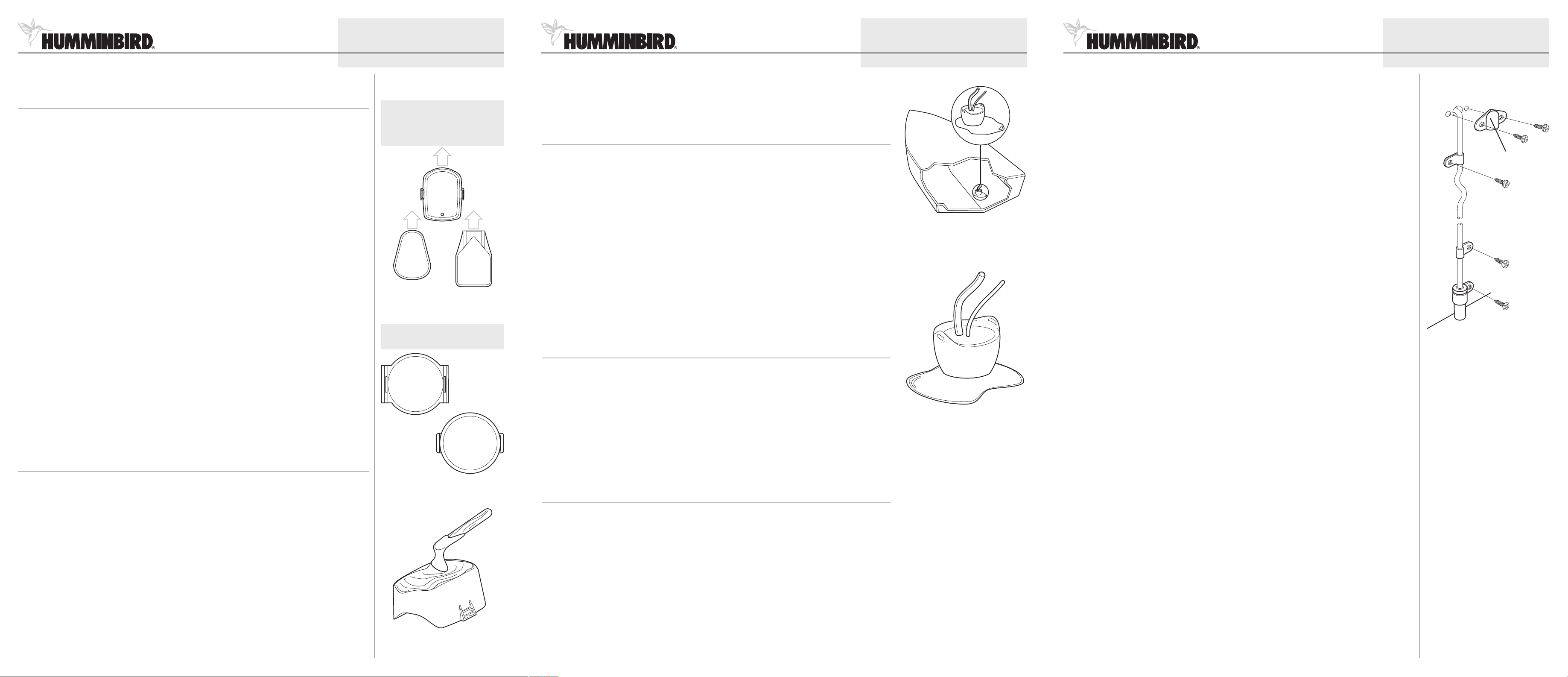
1. Either route the cable from the in-hull mounted transducer over the top of the transom, or drill a 5/8"
hole in the transom directly above the sensor, above the waterline.
CAUTION! The temperature probe incorporates a temperature-sensitive probe in a high-impact plastic housing
with 10 feet of cable. Do not cut or shorten the temperature probe cable, and try not to damage the cable
insulation. The probe is intended for installation on the transom and will work well on almost any boat.
2. Assemble the sensor in the clamp, and align it on the transom so the lower edge of the temperature
probe sensor is flush with the hull of the boat, and so that it doesn't extend below the hull. Mark
the hole location.
3. Drill a 1/8" mounting hole approximately 3/4" deep.
NOTE: On fiberglass hulls, it is best to start with a smaller bit and use progressively larger drill bits to reduce
the chance of chipping or flaking the outer coating.
4. Seal the mounting hole with marine-grade silicone sealant, and attach the sensor to the transom using
the screw provided.
5. If a thru-hole is used, an escutcheon plate is included to dress the hole. Place the escutcheon plate over
the cable hole and use it as a guide to mark thetwo escutcheonplate mounting holes.Remove the plate,
drill two 9/64" diameter x 5/8" deep holes, then fill all holes with marine-grade silicone sealant. Place
the escutcheon plate over the cable hole and attach with two #8 x 5/8" wood screws.
6. Route and secure the cable by attaching the supplied cable clamps to the transom; drill one 9/64"
diameter x 5/8" deep hole for each cable clamp, then fill hole with marine-grade silicone sealant, and
attach the cable clamp to the transom using a #8 x 5/8" screw.
7. If the connection is correct, the Humminbird® unit will begin displaying water temperature immediately.
If the gauge fails to read at high speeds, adjust the height of the sensor on the transom of your boat.
8. After final high-speed adjustments have been made, if a thru-hull hole was used, seal the hole with
marine-grade silicone sealant.
NOTE: The cabling from your transducer should already be routed from its location to the control head. The
cabling from the temperature probe goes into the transducer module and its readings are transferred through
the same cable to the control head. Refer to your control head installation guide for more information about
the quick disconnect or connector collector included with your control head.
Your control head is now ready for operation.
530509-4_C
Routing the Temp Probe Cable
Escutcheon Plate
3. Press the transducer into place with a slight twisting motion to purge any trapped air from underneath.
If you are using a transom-style transducer, make sure that the pointed end of the transducer points
forward to the bow of the boat. Position angled-style transducers to transmit straight down and remain
in parallel alignment with the keel.
NOTE: Puck or round, circular-bottomed transducers have no directional bias, and therefore orientation of
these types of transducers is not as important. Rounded rectangular transducers, however, do have a
directional bias. Refer to the part of the illustration that shows orientation for transducers with directional bias.
4. Weight the transducer so that it does not move while the epoxy is curing.
© 2008 Humminbird®, Eufaula AL, USA.
All rights reserved.
NOTE: The temperature probe is only available on certain models. Call the Customer Resource Center at
1-800-633-1468 for details and pricing, or visit www.humminbird.com for more information.
In addition to the parts supplied, you will need a hand drill with various size bits, marine-grade silicone
sealant, and various hand tools.
Temperature Probe Mounting Location: Locate an area on the transom of your boat 6"-8" or farther from
the transducer(s). This area must stay in contact with the water at high speeds. Do not mount the sensor
directly in front of the propeller or outdrive, and make sure that there are no protrusions such as ribs, rows
of rivets, or transducers directly forward of the mounting location, as these may affect the flow of water
over the temperature probe.
© 2008 Humminbird®, Eufaula AL, USA.
All rights reserved.
© 2008 Humminbird®, Eufaula AL, USA.
All rights reserved.
 Loading...