

Trolling Motor 360 Imaging
Trolling Motor 360 Imaging
Installation Guide
Installation Guide
532178-2_B
®
®
Thank You!
Thank you for choosing Humminbird®, the #1 name in marine electronics.
Humminbird has built its reputation by designing and manufacturing top-quality,
thoroughly reliable marine equipment. Your Humminbird accessory is designed for
trouble-free use in even the harshest marine environment. In the unlikely event that
your Humminbird does require repairs, we offer an exclusive Service Policy. For
complete details, see the separate warranty card included with your unit. We
encourage you to read this manual carefully in order to get the full benefit from all
the features and applications of your Humminbird product.
Contact Humminbird Customer Service by visiting our Web site at humminbird.com
or by calling 1-800-633-1468.
WARNING! This device should not be used as a navigational aid to prevent
collision, grounding, boat damage, or personal injury. When the boat is moving, water
depth may change too quickly to allow time for you to react. Always operate the boat
at very slow speeds if you suspect shallow water or submerged objects.
WARNING! The electronic chart in your Humminbird unit is an aid to navigation
designed to facilitate the use of authorized government charts, not to replace them.
Only official government charts and notices to mariners contain all of the current
information needed for the safety of navigation, and the captain is responsible for
their prudent use.
WARNING! Humminbird is not responsible for the loss of data files (waypoints,
routes, tracks, groups, recordings, etc.) that may occur due to direct or indirect damage
to the unit’s hardware or software. It is important to back up your control head’s data
files periodically. See your control head operations manual for details.
WARNING! Disassembly and repair of this electronic unit should only be
performed by authorized service personnel. Any modification of the serial number or
attempt to repair the original equipment or accessories by unauthorized individuals
will void the warranty.
NOTE: The illustrations in this manual may not look the same as your product, but
your unit will function in a similar way.
NOTE: To purchase accessories for your control head, visit our Web site at
humminbird.com or contact Humminbird Customer Service at 1-800-633-1468.

NOTE: The procedures and features described in this manual are subject to change
without notice. This manual was written in English and may have been translated to
another language. Humminbird is not responsible for incorrect translations or
discrepancies between documents.
NOTE: Product specifications and features are subject to change without notice.
NOTE: Humminbird verifies maximum stated depth in saltwater conditions, however
actual depth performance may vary due to transducer installation, water type, thermal
layers, bottom composition, and slope.
ATTENTION INTERNATIONAL CUSTOMERS:Products sold in the U.S. are not intended for
use in the international market. Humminbird international units provide international features
and are designed to meet country and regional regulations. Languages, maps, time zones,
units of measurement, and warranty are examples of features that are customized for
Humminbird international units purchased through our authorized international distributors.
To obtain a list of authorized international distributors, please visit our Web site at
humminbird.com or contact Humminbird Customer Service at (334) 687-6613.
360 Imaging®, Fortrex™, HELIX®, Humminbird®, Maxxum®, Minn Kota®, Ultrex™, and X-Press™ Menu are
trademarked by or registered trademarks of Johnson Outdoors Marine Electronics, Inc.
© 2017 Johnson Outdoors Marine Electronics, Inc. All rights reserved.

Table of Contents
Introduction 1
Install the GPS Receiver/Heading Sensor 3
1. Choose the Mounting Location. . . . . . . . . . . . . . . . . . . . . . . . . . . . . . . . . . . . . . . . 3
2. Install the Sensor. . . . . . . . . . . . . . . . . . . . . . . . . . . . . . . . . . . . . . . . . . . . . . . . . . . 4
A. Stem Mount with 1" - 14 Thread. . . . . . . . . . . . . . . . . . . . . . . . . . . . . . . . . . . . . 5
B. Access Under the Mounting Location. . . . . . . . . . . . . . . . . . . . . . . . . . . . . . . . . 7
C. No Access Under the Mounting Location. . . . . . . . . . . . . . . . . . . . . . . . . . . . . . 9
3. Connect to the Control Head. . . . . . . . . . . . . . . . . . . . . . . . . . . . . . . . . . . . . . . . . 11
Install the Trolling Motor Bracket 13
1. Prepare for Installation . . . . . . . . . . . . . . . . . . . . . . . . . . . . . . . . . . . . . . . . . . . . . 13
2. Install the Trolling Motor Bracket. . . . . . . . . . . . . . . . . . . . . . . . . . . . . . . . . . . . . . 14
A. Ultrex Trolling Motor Mount (AS 360 TM Ultrex). . . . . . . . . . . . . . . . . . . . . . . 14
B. Fortrex/Maxxum Trolling Motor Mount (AS 360 TM). . . . . . . . . . . . . . . . . . . . 27
3. Route the Cables and Connect Power. . . . . . . . . . . . . . . . . . . . . . . . . . . . . . . . . . 33
Set up the Control Head (HELIX Series) 36
1. Confirm Connections. . . . . . . . . . . . . . . . . . . . . . . . . . . . . . . . . . . . . . . . . . . . . . . 36
2. Set up 360 Imaging on the Control Head. . . . . . . . . . . . . . . . . . . . . . . . . . . . . . . 38
3. Test 360 Imaging on the Control Head . . . . . . . . . . . . . . . . . . . . . . . . . . . . . . . . . 39
4. Confirm the Heading Sensor Operation . . . . . . . . . . . . . . . . . . . . . . . . . . . . . . . . 40
5. Add Offset Features to the 360 Imaging Display (optional) . . . . . . . . . . . . . . . . . 42
6. Turn on NMEA Output and Confirm the Baud Rate
(for devices connected to the Sensor pigtail only) . . . . . . . . . . . . . . . . . . . . . . . . . . . . . . 44
7. Set up the Network and Alarms . . . . . . . . . . . . . . . . . . . . . . . . . . . . . . . . . . . . . . 44
Power Off 45
Maintenance 46
Control Head Maintenance. . . . . . . . . . . . . . . . . . . . . . . . . . . . . . . . . . . . . . . . . . . . 46
Transducer Maintenance. . . . . . . . . . . . . . . . . . . . . . . . . . . . . . . . . . . . . . . . . . . . . . 47
Trolling Motor 360 Imaging Maintenance. . . . . . . . . . . . . . . . . . . . . . . . . . . . . . . . . 47
i

Table of Contents
Troubleshooting 48
Fishing System Doesn’t Power Up. . . . . . . . . . . . . . . . . . . . . . . . . . . . . . . . . . . . . . . 48
Fishing System Defaults to Simulator with a Transducer Attached. . . . . . . . . . . . . 49
Finding the Cause of Noise. . . . . . . . . . . . . . . . . . . . . . . . . . . . . . . . . . . . . . . . . . . . . 50
Specifications 51
Contact Humminbird 53
ii


Introduction
This manual will guide you through the following installation requirements for the
Trolling Motor 360 Imaging:
Installing the GPS Receiver/Heading Sensor
Installing the Trolling Motor Bracket
Connecting to the Control Head and Power
Testing the Installation
Powering Off
Before proceeding with this installation, the Humminbird control head
and Minn Kota trolling motor should be installed. The 360 Imaging
transducer can be connected directly to the control head or to a
Humminbird Ethernet Switch (optional) for networking. See the Ethernet
Switch accessory guide to install the Ethernet Switch.
Compatibility
For the most current list of compatible accessories, visit our Web site at
humminbird.com.
The AS 360 TM Ultrex is compatible with the Minn Kota Ultrex.
The AS 360 TM is compatible with the Minn Kota Fortrex and the Minn Kota
Maxxum.
1
Introduction

Supplies
In addition to the hardware included with your accessory, you will need the following
supplies:
• Drill with various drill bits
• Phillips Head Screw Driver
• Allen wrench
• Hex socket wrench or nut driver
• Electrical Tape
• Awl or Pencil
• Marine-grade silicone caulk or sealant
• Cable ties for cable routing
• Tape measure
• 1 Amp fuse
• Safety goggles
• Dust mask
Switch (optional): If you do not have a main switch or fuse panel available on
your boat to connect power, you will need to purchase a battery switch. See
Install the Trolling Motor Bracket, Section 3: Route the Cables and Connect
Power for more information.
Cables: Depending on your Humminbird model and system configuration, you
may need to purchase additional cables, as shown below. Visit our Web site at
humminbird.com or call Humminbird Customer Service at 1-800-633-1468.
• HELIX Series with Ethernet: To connect the Ethernet to the control head,
you will need to purchase the Ethernet Adapter Cable (AS EC QDE).
• Extension Cables are available for Ethernet and the GPS Receiver/Heading
Sensor.
Introduction
2

Install the GPS Receiver/Heading Sensor
Use the following instructions to install the GPS Receiver/Heading Sensor (“Sensor”)
on your boat.
1 | Choose the Mounting Location
It is important to consider the following information when you choose a mounting
location for the Sensor:
• Interference: Do NOT mount the Sensor close to a VHF antenna or within the
active area of a radar. Do NOT install the Sensor near ferrous metals or near
anything that can create a magnetic field. Hardware and cables that handle
large currents, such as batteries and power cables, are also examples of
equipment that may cause interference.
• Reception: Mount the Sensor in an area that has full exposure to the sky.
The effective area of reception is 5˚ above the horizon.
• Surface: Whether the Sensor Cable will be routed down through the
mounting surface or to the side, or if you’re using a stem mount, the mounting
surface will influence how you install the Sensor. For details, see Section 2:
Install the Sensor.
• Extension Cables: Test run the Sensor Cable from the chosen mounting
location to the control head. 10 ft (3 m) extension cables may be purchased
from Humminbird if your planned cable route exceeds 20 ft (6 m). Maximum
cable length, including extension cables, should not exceed 50 ft (16 m).
3
GPS/Heading Sensor
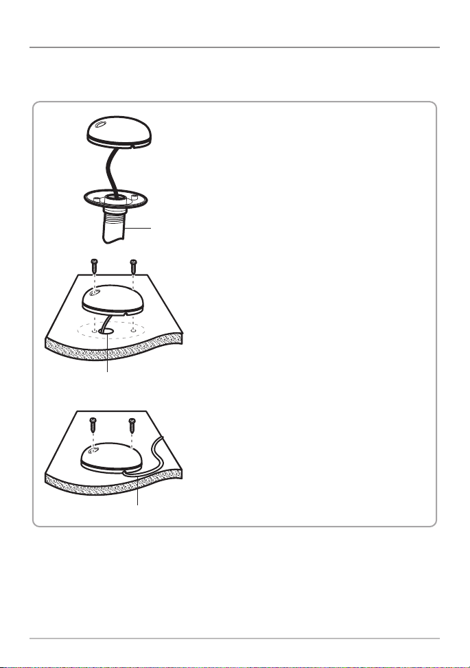
2 | Install the Sensor
There are three different options to mount the sensor. Proceed to the section that
matches the type of mounting location you will be using, as follows:
Stem Mount with 1" - 14 Thread
The Sensor will be mounted on a stem or
antenna pole. Proceed to Section A.
stem
Access Under the Mounting Deck
The Sensor will be deck mounted and the
cable can be routed down through the
mounting surface. Proceed to Section B.
cable routed through the hole
NO Access Under the Mounting Deck
The Sensor will be deck mounted and the
cable must be routed to the side because
there is not space for a cable through or
underneath the mounting location. Proceed
cable routed to the side
to Section C.
GPS/Heading Sensor
4
A. Stem Mount with 1"-14 Thread
Use the following instructions to stem mount the Sensor.
WARNING! Do NOT mount the Sensor to a stem
mount or antenna pole that contains ferrous metals.
NOTE: It is important to review the mounting
considerations and test run the cable route as
indicated in Section 1 before proceeding with the
installation.
1. If you have a pre-existing stem mount, skip to
step 2.
If you need to mount the antenna pole (stem),
mark the chosen mounting location and drill a
3/4" (19 mm) hole for the cable and cable
connector.
If you have purchased hardware to stem
mount your Sensor, follow the instructions
included with that hardware to attach the stem
to the boat.
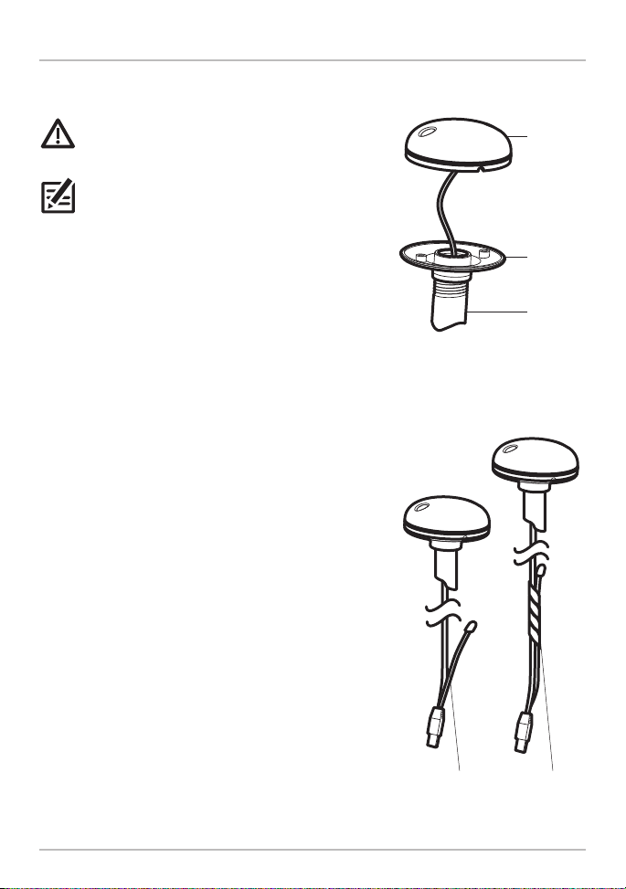
2. Screw the Sensor base onto the stem first,
making sure that the stem pipe does not
protrude from the Sensor base. (This adds
protection to the cable when it is pulled through
the pipe stem.) Deburr the pipe edges to reduce
cable abrasion.
Stem Mount, Attaching the
Sensor Base to the Stem
cover
base
stem
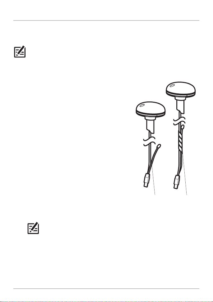
Taping the NMEA Pigtail
to the Cable
3. Use electrical tape to secure the NMEA pigtail
to the cable.
Unless it is needed, leave the NMEA pigtail
secured to the cable. If you are connecting the
pigtail to a NMEA 0183 device, see Section 3:
Connect to the Control Head for connection
information.
5
NMEA pigtail
cable out
NMEA pigtail
cable taped
GPS/Heading Sensor
4. Route the Sensor cable through the stem and
through the planned cable route. To use
extension cables, see the details in Section 1:
Choose the Mounting Location.
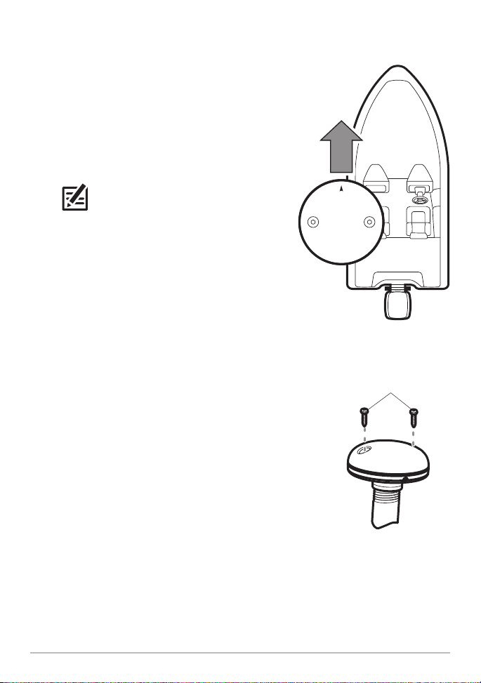
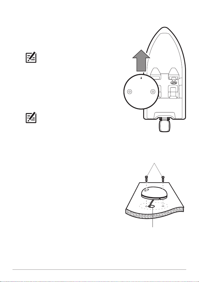
5. Position the Sensor so the arrow on the cover
is pointed straight toward the front of the boat
in the direction of travel. The arrow should be
parallel with the keel.
NOTE: Failure to align the Sensor correctly
will result in incorrect compass readings.
6. Attach the Sensor to its base using the
included #6 - 7/8" (22 mm) screws. Hand-
tighten only!
Positioning the Arrow
on the Sensor
Attaching the Sensor
to the Base
#6 - 7/8" mounting screws
GPS/Heading Sensor
6
B. Access Under the Mounting Location
Use the following instructions to deck mount the Sensor and route the cable down
through the mounting surface.
NOTE: It is important to review the mounting considerations and test run the cable
route as indicated in Section 1 before proceeding with the installation.
1. Mark the mounting location and drill a 3/4"
(19 mm) hole for the cable and cable connector.
2. Secure the NMEA pigtail to the cable with
electrical tape.
Unless it is needed, leave the NMEA pigtail
secured to the cable. If you are connecting the
pigtail to a NMEA 0183 device, see Section 3:
Connect to the Control Head for connection
information.
3. Route the Sensor cable through the planned
cable route. To use extension cables, see the
details in Section 1: Choose the Mounting
Location.
4. Cover the cable hole with the Sensor.
Position the Sensor so the arrow on the cover
is pointed straight toward the front of the boat
in the direction of travel. The arrow should be
parallel with the keel.
NOTE: Failure to align the Sensor correctly
will result in incorrect compass readings.
Taping the NMEA Pigtail
to the Cable
NMEA pigtail
cable out
NMEA pigtail
cable taped
7
GPS/Heading Sensor
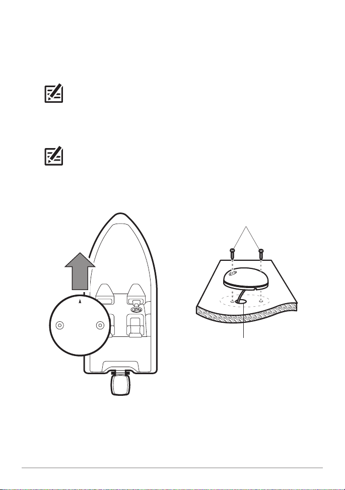
5. Make sure the Sensor is flush against the surface, and mark the two
mounting holes with a pencil or awl.
6. Move the Sensor to the side and drill two pilot holes, using a 5/32"
(4 mm) bit.
NOTE: Apply marine-grade silicone caulk or sealant to both screw and drilled
holes as needed to protect your boat from water damage.
7. Align the Sensor screw holes over the pilot screw holes and attach with the
#8 - 1¼" (32 mm) Phillips head screws. Hand-tighten only!
NOTE: If the mounting surface is thin or made of a light-weight material, you
may need to add reinforcing material below the mounting surface in order to
support the Sensor.
Positioning the Arrow
GPS/Heading Sensor
on the Sensor
Attaching the Sensor to the
Mounting Surface
#8 - 1¼" mounting screws
cable routed through the hole
8
C. No Access Under the Mounting Location
Use the following instructions to deck mount the Sensor and route the cable to the
side if there is not space for a cable underneath the mounting location.
NOTE: It is important to review the mounting considerations and test run the cable
route as indicated in Section 1 before proceeding with the installation.
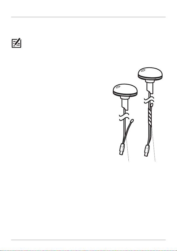
1. Secure the NMEA pigtail with electrical tape.
Unless it is needed, leave the NMEA pigtail
secured to the cable. If you are connecting the
pigtail to a NMEA 0183 device, see Section 3:
Connect to the Control Head for connection
information.
2. Route the cable from the Sensor to the Control
head.
• The Sensor has two wire routing notches.
Use the cable notch closest to the
intended cable route.
• If holes are required to route the cable,
they must be 3/4" (19 mm) to allow for the
cable connector.
• To use extension cables, see the details in
Section 1: Choose the Mounting Location.
Taping the NMEA Pigtail
to the Cable
NMEA pigtail
cable out
NMEA pigtail
cable taped
9
GPS/Heading Sensor
3. With the cable routed, position the Sensor so
the arrow on the cover is pointed straight
toward the front of the boat in the direction of
travel. The arrow should be parallel with the
keel.
NOTE: Failure to align the Sensor correctly
will result in incorrect compass readings.
4. Make sure the Sensor is flush against the
surface, and mark the two mounting holes
with a pencil or awl.
5. Move the Sensor to the side and drill the two
5/32" (4 mm) pilot holes.
NOTE: Apply marine-grade silicone caulk
or sealant to both screw and drilled holes as
needed to protect your boat from water
damage.
6. Align the Sensor screw holes over the pilot
screw holes and attach with the #8 - 1¼"
(32 mm) Phillips head screws. Hand-tighten
only!
Positioning the Arrow
on the Sensor
Attaching the Sensor to the
Mounting Surface
#8 - 1¼" mounting screws
GPS/Heading Sensor
cable routed through the hole
10
3 | Connect to the Control Head
Use the following instructions to connect the Sensor cable to the control head.
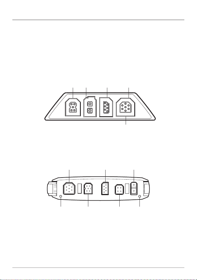
1. Insert the Sensor NMEA-COM connector into the control head COM port.
The connectors are keyed to prevent reversed installation, so be careful not
to force the connector into the port. See your control head installation guide
for details.
HELIX 7 Control Head Ports
COM
(communications)
Optional: Use a Y-Cable to connect
Transducer and Speed Sensor Accessory
COM
(communications)
transducer
power
transducer
power
Ethernet
HELIX 9, 10, 12 Cable Tray
Ethernet temp/speedpin pin
11
GPS/Heading Sensor
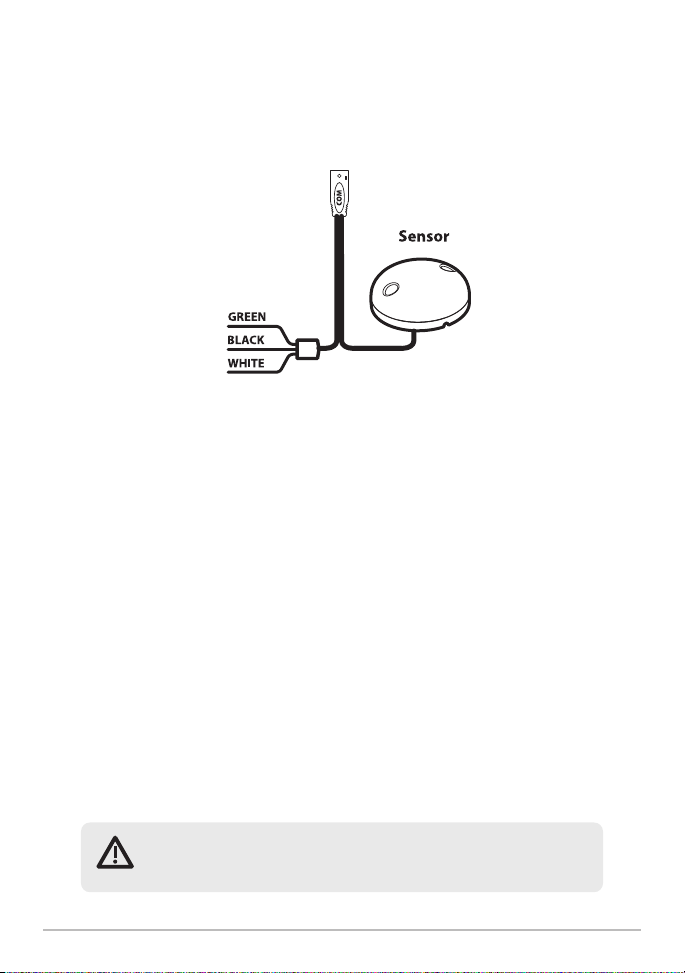
2. Optional: You can connect an optional-purchase device, such as an autopilot,
to the Sensor pigtail wires.
GPS Receiver/Heading Sensor
(Optional Accessory Wires)
The pinouts are as follows:
Black Wire (Ground)
White Wire (Control Head NMEA Out): outputs the navigation calculations
and commands from the control head as IN (Integrated Navigation) NMEA
sentences. Connect the white wire to the device’s NMEA In wire.
OR
Green Wire (GPS NMEA Out): outputs GP (Global Positioning) NMEA
sentences directly from the Sensor. Connect the green wire to the device’s
NMEA In wire if it can only read GP NMEA sentences.
See your device installation guide to identify the NMEA In wire. The device
will connect to the white wire or green wire, depending on its NMEA
communication requirements (IN or GP).
See Section 6: Turn on NMEA Output and Confirm the Baud Rate for more
information.
WARNING! It is important to finish all installation connections
before powering on the control head.
GPS/Heading Sensor
12
 Loading...