

Humminbird Transducer Installation Manual
1
TRANSDUCER Installation Guide
It is important to read the instructions in this transducer guide completely to understand the
mounting guidelines before starting the installation.
NOTE: Due to the wide variety of hulls, only general instructions are presented in this installation
guide. Each boat hull represents a unique set of requirements that should be evaluated prior to
installation. For detailed information about installing transducers on different hull types,
download the Transducer Installation Resource Guide from our Web site at humminbird.com.
NOTE: Your transducer may not look exactly like the transducer shown in the illustrations, but it
will mount in exactly the same way.
I P
Install the control head before you start the transducer installation. See the control head
installation guide.
Review your boat manufacturer’s owner’s manual for recommended transducer installation
locations and cable routing methods. You will also need your transom angle.
Read and understand your boat’s warranty before starting this installation.
532310-3_A
Visit our Web site at humminbird.com for additional information and resources for transducer
installations. Also, visit youtube.com/humminbirdtv for informational videos.
Confirm your boat is level for the installation.
Installation Options: If you cannot find a transom mount location that will work for your
high-speed application, you may consider an Inside the Hull installation. Visit our Web site at
humminbird.com to download instructions.
Supplies: In addition to the supplied hardware, you will need a powered hand drill and various drill
bits, various hand tools, including a ruler or straightedge, a level, a socket driver, marker or pencil,
safety glasses and dust mask, marine-grade silicone sealant, dielectric grease (optional), and a
12" (30.5 cm) plumb line (weighted string or monofilament line) (optional). You may also need
extension cables and hardware for routing the cable to the control head.
T-F M G
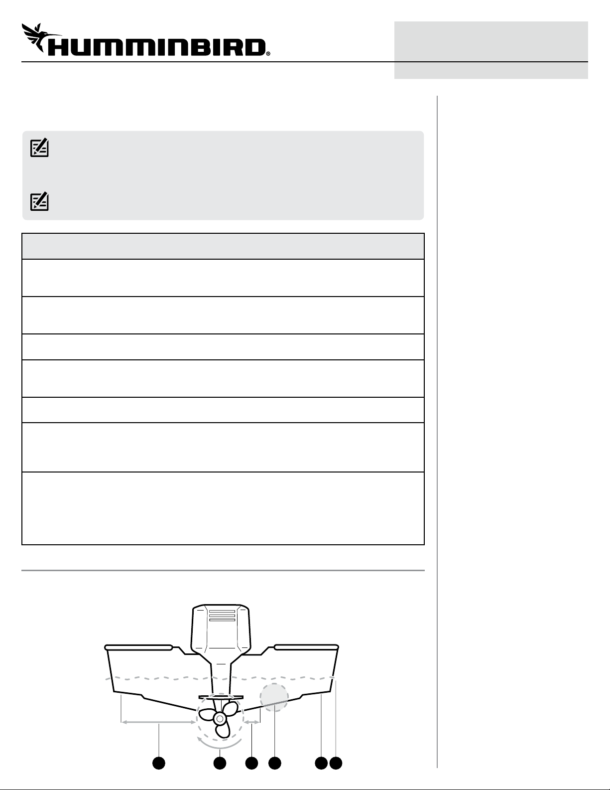
It is very important to locate the transducer in an area that is relatively free of turbulent water.
Consider the following to find the best location with the least amount of turbulence:
1 3 4 5 62
2
TRANSDUCER Installation Guide
Avoid areas where there is turbulent water flow. Turbulent water is normally confined to areas
1
immediately aft of ribs, strakes, or rivets on the bottom of the boat, and in the immediate area
of the propeller(s). The best way to locate turbulence-free water is to view the transom while
the boat is moving.
Observe your propeller’s direction of rotation (in forward, as you're facing the stern of the boat
2
from behind). Clockwise propellers create more turbulence on the port side. Counterclockwise
propellers create more on the starboard side.
Ensure there is adequate distance from the propeller(s). On outboard or inboard/outboard
3
boats, it is best to locate the transducer at least 15" (38.1 cm) to the side of the propeller(s).
The ideal mounting location (right of the propeller[s]). It is important to note that if you plan
4
to trailer your boat, do not mount the transducer too close to trailer bunks or rollers to avoid
moving or damaging the transducer during loading and unloading of the boat.
For boats with stepped hulls, it may be possible to mount the transducer on the step. Do not
5
mount the transducer on the transom behind a step to avoid popping the transducer out of the
water at higher speeds.
The transducer must be mounted so that it is parallel with the waterline, but fully submerged
6
in the water during operation.
532310-3_A
Deadrise: The hydrodynamic shape of your transducer allows the sonar beams to point down
without deadrise adjustment.
| Prepare the Mounting Location
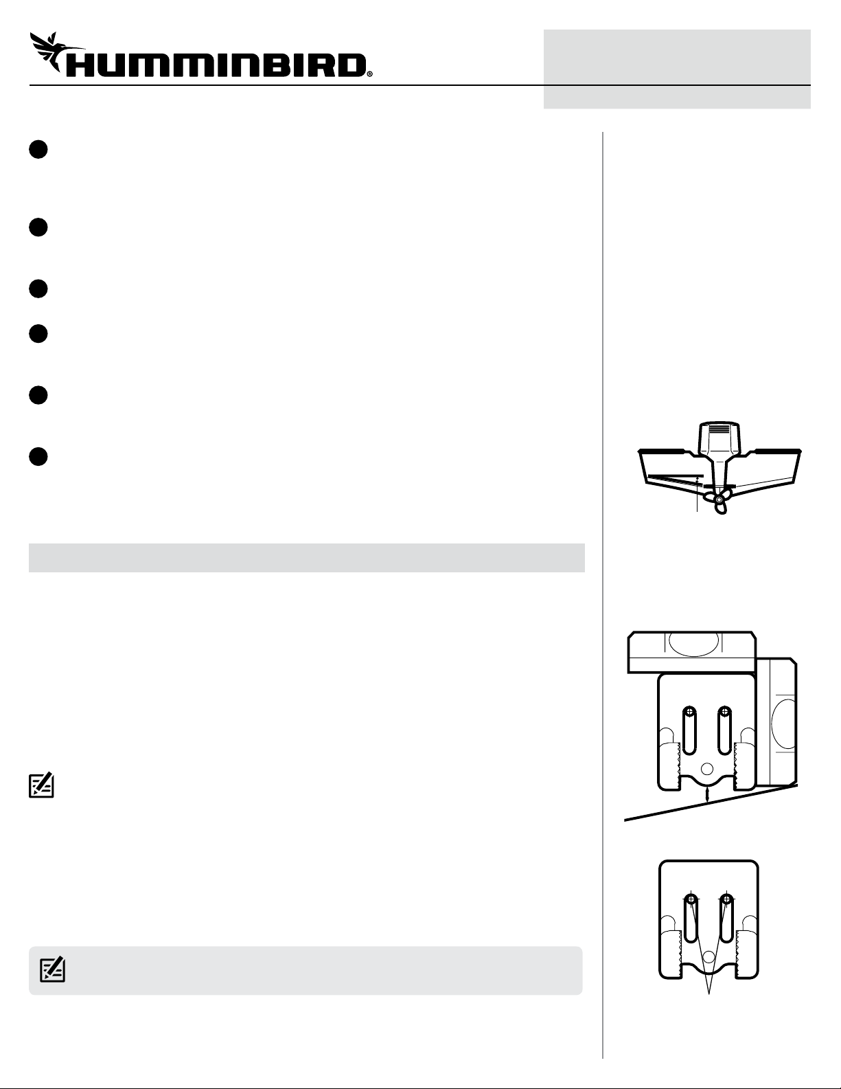
1
1. Confirm the boat is level on the trailer (both from port to starboard and from bow to stern).
2. Hold the mounting bracket against the transom of the boat in the location you have selected.
Align the bracket horizontally, using the level. Make sure that the lower screw hole protrusion
does not protrude past the bottom of the hull.
Refer to the minimum clearance requirement between the bottom of the bracket and the
bottom of the transom for your boat type below:
1/4" (6 mm) clearance for fiberglass boats
1/8" (3 mm) clearance for aluminum boats
NOTE FOR ALUMINUM BOATS: For flat-bottomed aluminum boats, some additional adjustment
may be needed to accommodate the rivets on the bottom of the boat (the gap may need to be a
little smaller than 1/8"). This will help you to avoid excessive turbulence at high speeds.
If your propeller moves clockwise, mount the transducer on the starboard side. If your
propeller moves counterclockwise, mount the transducer on the port side.
3. Continue to hold the bracket on the transom of the boat, and use a pencil or marker to mark
where to drill the two mounting holes. Mark the drill holes near the top of each slot, making
sure that your mark is centered in the slot (see Using the Mounting Bracket to Mark the Initial
Drill Holes).
deadrise angle
Using the Mounting Bracket
to Mark the Initial Drill Holes
LEVEL
LEVEL
1/4" for fiberglass
1/8" for aluminum
NOTE: The third hole should not be drilled until the angle and height of the transducer is finalized,
which you will not do until a later procedure.
4. Confirm that the drill bit is perpendicular to the actual surface of the transom, (NOT parallel
to the ground), before you drill. Using a 5/32" (4 mm) bit, drill the two holes only to a depth of
approximately 1" (25.4 mm).
mark initial drill holes
3
TRANSDUCER Installation Guide
NOTE FOR FIBERGLASS HULLS: It is best to start with a smaller bit and use progressively larger
drill bits to reduce the chance of chipping or flaking the outer fiberglass coating.
| Assemble the Transducer and Initial Mounting
2
You will initially assemble the transducer and the mounting bracket (using the hardware provided)
by matching the two ratchets to a numbered position on the transducer knuckle, then mount it and
make adjustments to its position without locking it in place.
1a. If your transom is angled at 14 degrees (a common transom angle for many boats), use
position 1 for the ratchets.
1b. If you have a different transom angle or do not know your transom angle, refer to the
Transducer Installation Resource Guide on our Web site at humminbird.com for detailed
instructions.
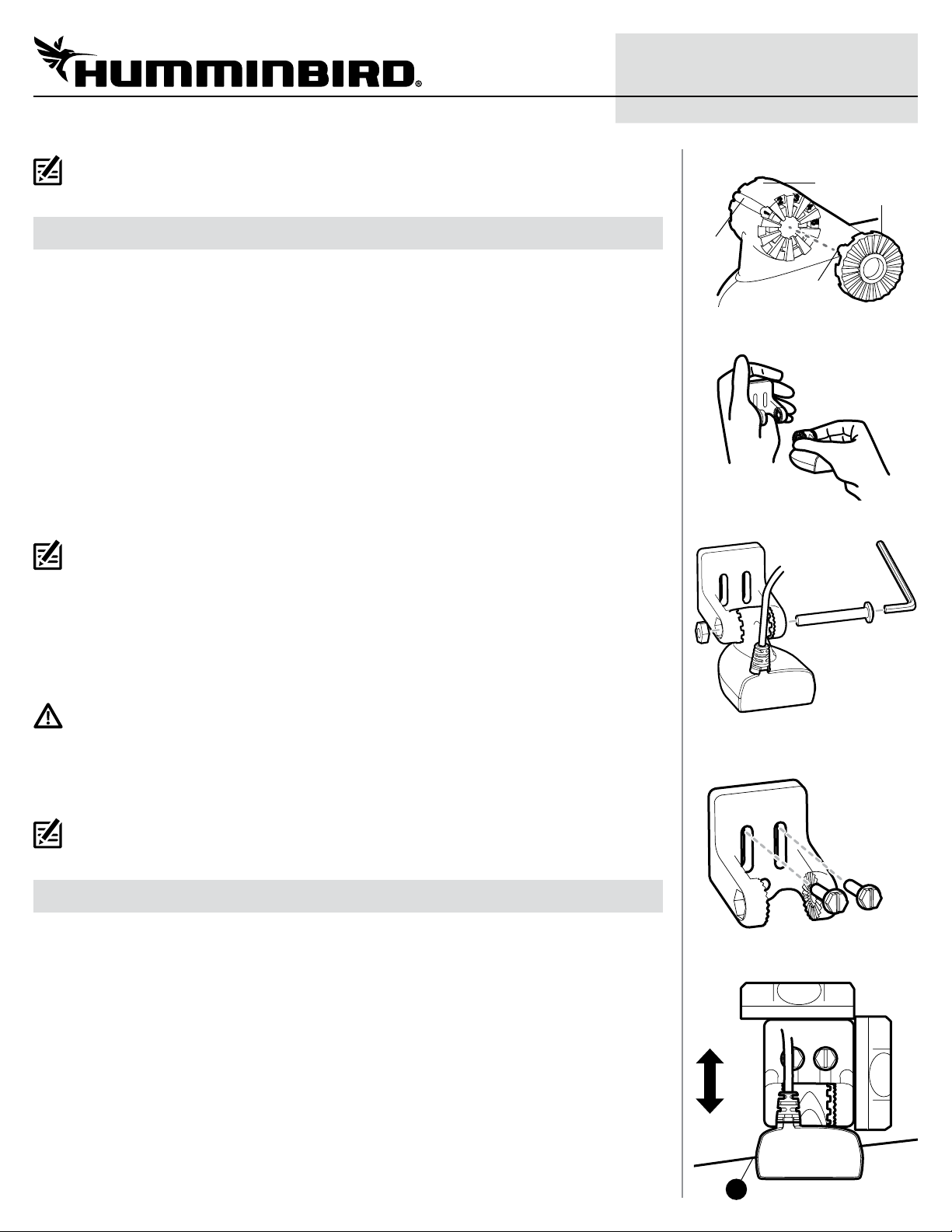
2. Place the two ratchets, one on either side of the transducer knuckle, so that the beads on each
ratchet line up with the desired position number on the knuckle (see Installing the Ratchets in
Position 1). If you are setting the ratchets at position 1, the beads on each ratchet will line up
with the rib on the transducer knuckle to form one continuous line on the assembly.
NOTE: The ratchets are keyed. Make sure that the square teeth on each ratchet face the square
teeth on the transducer knuckle, and the triangular teeth face outward.
532310-3_A
Installing the Ratchets in Position 1
knuckle
ratchet
rib at
position
1
bead
Fitting the Mounting Bracket
Over the Ratchet
Installing the Pivot Bolt
3. Hold the ratchets on the transducer knuckle with one hand and fit the mounting bracket over
them until it snaps into place with the other hand. Refer to the illustration Fitting the Mounting
Bracket Over the Ratchet.
4. Put the pivot bolt through the assembly to hold it in position and loosely install the nut, but do
NOT tighten the nut at this time (see Installing the Pivot Bolt).
CAUTION! Do not use a high speed driver on this combination of fasteners. Hand-tighten only.
5. Align the mounting bracket transducer assembly with the drilled holes in the transom. With a
5/16" (8 mm) socket driver, mount the assembly to the transom using the two #10 - 1" (25.4
mm) long screws provided. Hand-tighten only!
NOTE: Make sure that the mounting screws are snug, but do not fully tighten the mounting screws
at this time to allow the transducer assembly to slide for adjustment purposes.
| Confirm the Mounting Angle
3
You will need to adjust the initial angle of the transducer both vertically and horizontally to confirm
the transducer mounting angle.
1. Adjust the transducer assembly vertically, until the seam on the leading edge of the transducer
(the edge closest to the transom of the boat) is level and just slightly below the hull.
2. Adjust the initial angle of the transducer from back to front by rotating the transducer until
the side seam on the transducer is almost parallel with the bottom of the boat, one click at a
time in either direction (see Adjusting the Initial Transducer Angle).
Mounting the Assembly
to the Transom
Adjusting the Transducer
Mounting Position
LEVEL
LEVEL
Downward Slant: The transducer has a natural downward slant of 4 to 5 degrees from leading
edge (closest to the boat transom) to trailing edge (farthest away from the boat). Looking at
the back of the transducer, the seam should be slightly below the bottom of the hull.
4
Correctly aligned.
4
TRANSDUCER Installation Guide
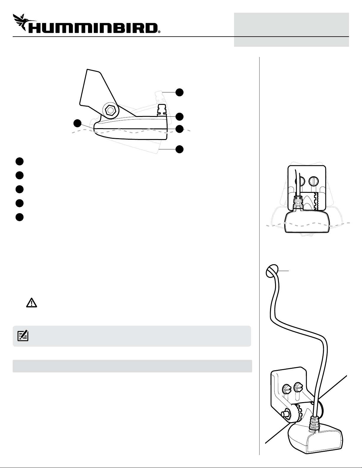
Adjusting the Initial Transducer Angle
2
3
1
Leading edge (the edge closest to the transom of the boat).
1
One click too high: the transducer is tilted out of the water and cannot maintain a sonar signal.
2
Trailing edge (the edge farthest away from the boat).
3
Correctly aligned: the transducer side seam is parallel with the water line.
4
4
5
532310-3_A
Adjusting the Horizontal
Transducer Angle
One click too low: the deeper the transducer is in the water, the more likely that a rooster tail
5
of spray will be generated at high speeds. You also risk the transducer being struck and
damaged by objects in the water, so make sure that the transducer is as high as it can be and
still be submerged in the water.
3. Continue to adjust until the bracket is also level from port to starboard (horizontally level as
you look at the transducer from behind the boat) (see Adjusting the Horizontal Transducer
Angle).
4. Once finalized, mark the correct position on the transom by tracing the silhouette of the
transducer mounting bracket with a pencil or marker.
5. Tighten the pivot bolt, using the pivot screw and nut to lock the assembly. Hand-tighten only!
CAUTION! Do not use a high speed driver on this combination of fasteners. Hand-tighten only.
6. Hand-tighten the two mounting screws.
NOTE: You will drill the third mounting hole and finalize the installation after you route the cable
and test and finish the installation in the following procedures.
Route the Cable
4 |
You can route the cable over the transom or through a hole in the transom above the waterline.
Your boat may have a pre-existing wiring channel or conduit that you can use to route the cable.
Select the routing method that is best for your boat configuration, and purchase any extension
cables, cable clips, clamps, etc. as needed.
Routing the Cable
Fill drill holes with
marine-grade silicone
sealant.
Also, keep in mind the following:
Δ It is best to route the cable to the side of the transducer so the transducer will not damage
the cable during movement.
Δ Allow enough slack in the cable for slight movement at the pivot point.
Δ If you drill any holes, fill them with marine-grade silicone sealant.
5
TRANSDUCER Installation Guide
Δ Excess Cable: If there is excess cable that needs to be gathered at one location, dress the
cable routed from both directions so that a single loop is left extending from the storage
location. Doubling the cable up from this point, form the cable into a coil. Storing excess cable
using this method can reduce electronic interference.
CAUTION! Do not cut or shorten the transducer cable, and try not to damage the cable insulation.
Route the cable as far as possible from any VHF radio antenna cables or tachometer cables to
reduce the possibility of interference. If the cable is too short, extension cables are available to
extend the transducer cable up to a total of 50'. For assistance, contact Humminbird® Technical
Support.
CAUTION! Do NOT mount the cables where the connectors could be submerged in water or flooded.
If cables are installed in a splash-prone area, it may be helpful to apply dielectric grease to the
inside of the connectors to prevent corrosion. Dielectric grease can be purchased separately from
a general hardware or automotive store.
Connect the Cable
5 |
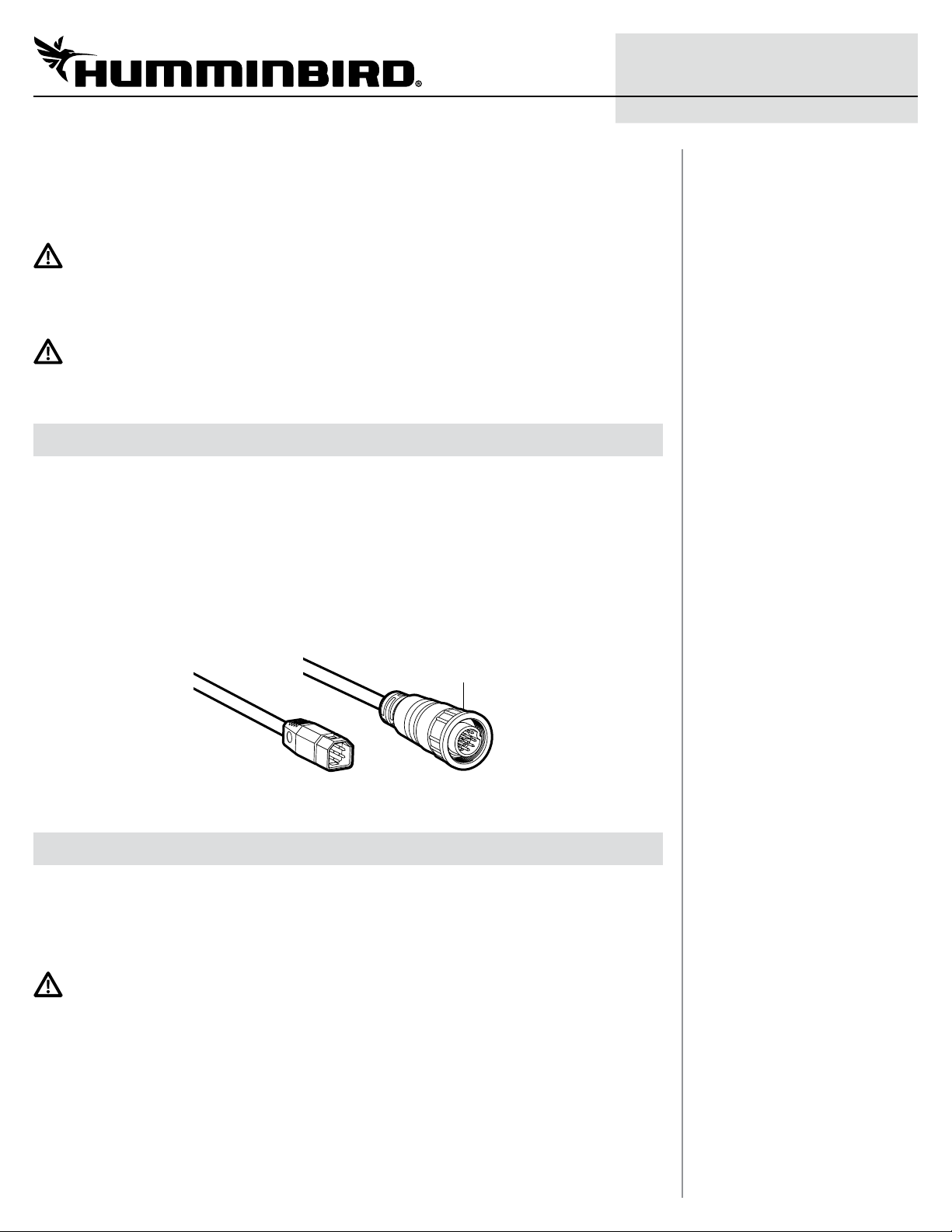
1. Connect the transducer cable to the transducer port on the control head or cable connector
(if applicable).
The connector is keyed to prevent reversed installation, and insertion should be easy. Do not
force the connectors into the ports.
If the cable connector is round, hand-tighten the screw nut to secure the cable connection.
Hand-tighten only!
Refer to your control head installation guide for additional details.
532310-3_A
Transducer Connectors
screw nut
Hexagon-Shaped
Connector
Test and Finish the Installation
6 |
Once you have installed the control head, the transducer, and have routed all the cables, you must
perform a final test before locking the transducer in place.
Testing should be performed with the boat in water deeper than 2 feet. The transducer should be
fully submerged because the sonar signal cannot pass through air.
WARNING! The transducer must be fully submerged in water during operation because the sonar
signal cannot pass through air. Air pinging can damage the transducer.
Test the Transducer Installation on the Control Head
1. Press the POWER key to turn on the control head.
If the transducer is detected, the control head will start Normal mode.
Round
Connector
2. Select a Sonar View to display on-screen.
HELIX®: Press and hold the VIEW key. Select Sonar > Sonar View.
SOLIX®: Press the HOME key. Select a Sonar View.
Other: See your control head operations manual.
 Loading...