

Humminbird TFX160 Operation Manual

TFX1 60
Operations Manual

THANK YOU
Thank you for choosing Teleflex Sonar, manufactured by Techsonic
Industries, for your sonar fishfinder and depthsounder. Techsonic has built
its reputation by designing and manufacturing top-quality, thoroughly
reliable marine equipment. Techsonic has designed your Teleflex Sonar
unit to be trouble free even in the harshest marine environments.
In the unlikely event that your Teleflex Sonar product does require repairs,
Techsonic offers an exclusive Service Guarantee - free of charge during
the first year after purchase, and available at a reasonable rate after the
one-year period. Complete details are included at the end of this manual.
We encourage you to read this operations manual carefully in order to
get full benefit from all the features and uses of your Teleflex Sonar
product. Also, to register your purchase and help us learn more about
you, please fill out the included warranty registration card
WARNING! This device should not be used as a navigational aid to
prevent collision, grounding, boat damage, or personal injury.
When the boat is moving, water depth may change too quickly to
allow time for you to react. Always operate the boat at very slow
speeds if you suspect shallow water or submerged objects.
WARNING:
service personnel. Any modification of the serial number or attempt to repair the original equipment or
accessories by unauthorized individuals will void the warranty.Handling and/or opening this unit may result
in exposure to lead,in the form of solder.
WARNING: This product contains lead, a chemical known to the State of California to
cause cancer and birth defects and other reproductive harm.
Dis-assembly and repair of this electronic unit should only be performed by authorized

TABLE OF CONTENTS
Section 1: INSTALLATION PREPARATION . . . . . . . . . . . . . . . 2
Parts Supplied . . . . . . . . . . . . . . . . . . . . . . . . . . . . . . 2
Accessories . . . . . . . . . . . . . . . . . . . . . . . . . . . . . . . . 2
Installation Overview . . . . . . . . . . . . . . . . . . . . . . . . . 2
Alternative Transducers and Mounting Methods. . . . . . 4
Section 2: USING THE
160
Performance . . . . . . . . . . . . . . . . . . . . . . . . . . . . 5
Simulator and Feature Memory. . . . . . . . . . . . . . . . . . 6
Control Functions . . . . . . . . . . . . . . . . . . . . . . . . . . . . 7
Knobs. . . . . . . . . . . . . . . . . . . . . . . . . . . . . . . . . 7
Real Time Sonar Window . . . . . . . . . . . . . . . . . . . 9
Chart Window. . . . . . . . . . . . . . . . . . . . . . . . . . 10
Modes of Operation. . . . . . . . . . . . . . . . . . . . . . . . . 12
Automatic Mode . . . . . . . . . . . . . . . . . . . . . . . . 12
Bottom Lock Zoom Mode. . . . . . . . . . . . . . . . . . 14
Manual Mode . . . . . . . . . . . . . . . . . . . . . . . . . . 15
Control Panels . . . . . . . . . . . . . . . . . . . . . . . . . . . . . 16
Section 5: MAINTENANCE AND WARRANTY. . . . . . . . . . . 21
Maintenance . . . . . . . . . . . . . . . . . . . . . . . . . . . . . . 21
Troubleshooting . . . . . . . . . . . . . . . . . . . . . . . . . . . . 21
Warranty . . . . . . . . . . . . . . . . . . . . . . . . . . . . . . . . . 25
Service Policy . . . . . . . . . . . . . . . . . . . . . . . . . . . . . . 25
Customer Support . . . . . . . . . . . . . . . . . . . . . . . . . . 26
Specifications. . . . . . . . . . . . . . . . . . . . . . . . . . . . . . 27
160
. . . . . . . . . . . . . . . . . . . . . . . . . 5

INSTALLATION PREPARATION
PARTS SUPPLIED
PARTS SUPPLIED
Before installing your 160, please ensure the following parts are included
in the box:
• 160 fishfinder
• Transducer with 20' (6m) of cable and mounting hardware kit
• Mounting system and mounting hardware kit
• 6' (2m) power cable
• Speed/Temperature Sensor and mounting hardware
• Collector Plug
• Publications kit
If any of these items are missing, call our Customer Support Hotline listed
in the end of this manual.
ACCESSORIES
Techsonic offers a wide assortment of accessories that complement and
expand the capability of your new 160. These accessories are designed
with the same high standards and are backed by the same one-year
warranty. All sonar accessories are available through your full-service
dealer or factory direct through our number listed in the Customer Support
section.
INSTALLATION OVERVIEW
All 160 Series consists of three primary components to install: the control
head, the transducer and the speed/temp sensor.
The control head contains the sonar transmit and receive circuitry, as well
as the user controls and display. It should be installed in a location that
provides access to the controls and visibility while in use. The control head
mounts on a gimbal mounting system that tilts and swivels providing
flexibility for viewing from different locations on the boat. In addition, the
160 can be mounted in the boat console.
2
INSTALLATION PREPARATION
INSTALLATION OVERVIEW
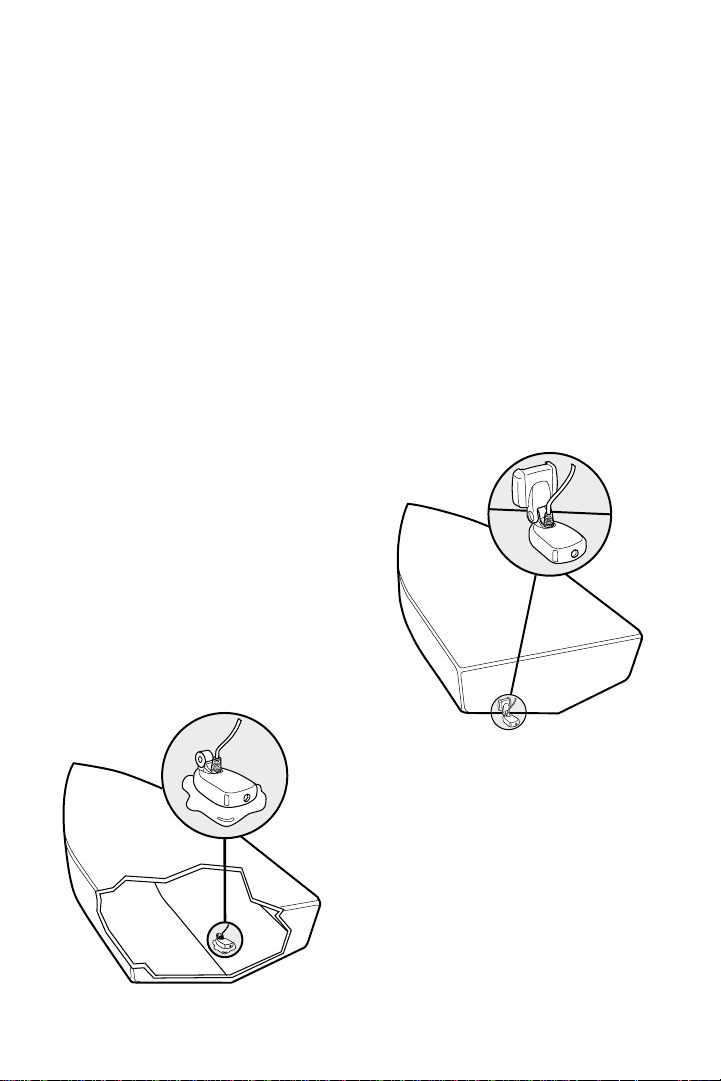
The speed/temperature sensor takes readings from the water at the
surface. It should be installed in contact with the surface of the water in an
area that has smooth water flow - usually on the transom of the boat.
Refer to the speed/temperature installation sheet included.
The transducer converts electrical energy from the transmitter into
mechanical pulses or sound waves. The transducer also receives the
reflected sound waves and converts them back into electrical signals for
display on the control head. It should be installed in contact with the
surface of the water in an area that has smooth water flow - usually on the
transom of the boat. There are several mounting options for the
transducer. Review the following section to determine the method that
works for you and your boat.
Determining How to Mount the
Transducer
The 160 includes a model TZ160H
transducer. This transducer can be
mounted on the transom of the boat,
or bonded to the inside of a fiberglass
hull boat.
Inside the Hull Mounted Transducer
Transom Mounted Transducer
The transom installation, which is the
most widely used, places the transducer
on the outside of the boat hull. This
technique produces the least signal loss,
and provides a way to adjust the
transducer after installation. The
mounting hardware included is
designed to protect both the boat and
the transducer should the boat strike
debris in the water or when trailering.
3

INSTALLATION PREPARATION
ALTERNATE TRANSDUCERS AND MOUNTING METHODS
As an alternative to transom mounting, it is possible on many fiberglass-hulled
boats to glue the transducer on the inside of the boat hull. Since fiberglass has
similar sonar characteristics as water , the sonar signal can pass thr ough the boat
hull with minimal loss. The hull of the boat must be single layer construction (not
double-hulled). Also, any air trapped in the lamination of the fiberglass would
prevent the sonar signal from passing through.
Inside the hull installations require no holes to be drilled into the boat and through
experimentation, high-speed operation comparable to transom mounting can be
achieved. Two part, slow cure epoxy is required to glue the transducer in place.
ALTERNATE TRANSDUCERS AND MOUNTING METHODS
The 160 comes with everything necessary for installation and operation on
most boats. However , ther e are several situations which may r equire a dif ferent
type of transducer. Inboard boats, wood or metal hulls, and sail boats create
unique transducer mounting needs. Alternate transducers and mounting
methods are detailed below.
Trolling Motor Mounting
The standard high-speed transducer can also be adapted to mount on most
trolling motors using part number AD-STM-7. This accessory includes a bracket
and hose clamp that allows mounting the transducer to the body of most
trolling motors.
BEGINNING INSTALLATION
Now that you have determined the transducer mounting method, you can
begin installation of the 160. The fold out installation guide included provides
detailed step by step instructions for installation of the control head, transducer
and speed/temp sensor. For transom mount transducer installations, you will
need the mounting template at the front of this manual.
4

USING THE 160
160 PERFORMANCE
In addition to the parts included you need the following for installation and operation:
• A powered hand drill and various drill bits
• Phillips and flat-head screw drivers
• A ruler or measuring tape
• Pen or pencil
• 12 volt power source (your boat’s battery)
• Silicone sealant (for sealing drilled holes)
• 2-part, slow-cure epoxy (for inside the hull transducer installations)
USING THE 160
160 Performance
The 160 Series represents a new way of thinking about fishing electronics.
Combining state of the art electronics and paper chart recorder sonar
performance, it offers the best of the present and the past. Minimal, easy
to understand knob controls provide access to the most important features.
The 160 eliminates confusion created by too many buttons and menus.
High technology, high performance, with "back to basics" operation
makes the 160 the ideal choice of the serious angler.
The 160 uses sonar to locate and define underwater objects. Sonar
technology is based on sound waves sent into the water in a controlled
"beam" from the transducer. Objects within this beam reflect the sonar
signal back. The 160 very accurately measures the distance to these objects
based on the time it takes for the sonar to return. Each object (bottom, fish
or structure) reflects the sonar uniquely, providing information about its
makeup. The 160 draws this returned information on the display.
The 160 operates in a wide variety of water conditions, from 2’ to 600’.
Actual depth capability depends on many factors such as bottom hardness,
water conditions, and transducer installation. All sonar units typically read
to deeper depths in fresh water than saltwater.
5

USING THE 160
SIMULATOR AND FEATURE MEMORY
POWERING UP THE 160
After installation, turn the 160 on by momentarily pressing the Gain knob.
An audible chirp sounds as the unit turns on. If the unit detects that the
transducer is connected and is in water, the 160 begins to show sonar
information on the display. If the transducer is not detected, the unit starts
up in simulator mode.
To power the unit off at any time, press and hold the Gain knob for several
seconds until the 160 turns off.
Simulator and Feature Memory
The 160contains a simulator that allows you to use the unit as though you are on the
water . The Simulator is an invaluable aid to learning the features and functions of the
160. All controls are operational and settings can be changed to experiment with
various features. When operating in Simulator an indicator appears at the bottom left
of the display .
There are two ways to start the simulator. The method to use depends on whether a
transducer is connected:
If the 160is powered on with no transducer connected, it starts up in simulator mode.
No other steps are needed. In this mode the 160 does not remember any setting
changes that are made.
If the 160 is powered on with the transducer connected, the Simulator must be
manually turned on.
To manually turn the simulator on:
1. Press the Control Panel knob to display the
list of options.
2. Rotate the Control Panel knob to scroll
through the list until Simulator is visible and is
highlighted on the display.
3. Turn the Range knob to turn Simulator from
OFF to ON.
4. Press the Control Panel knob to clear the screen.
6
USING THE 160
CONTROL FUNCTIONS
When operating with the Simulator on and the transducer connected
changes made to Chart Speed, RTS Window, Surface Clutter, Contrast,
White Line, (language in international models,) and the Units Control
Panels are permanently remembered. When a transducer is not connected,
changes are not remembered.
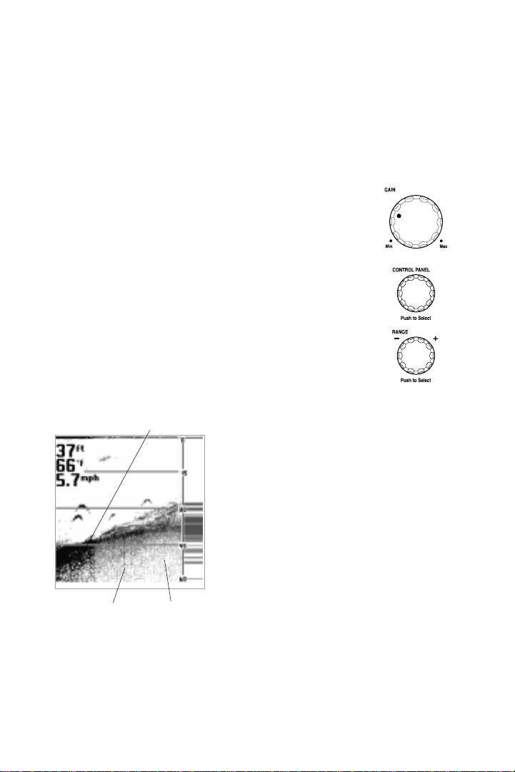
CONTROL FUNCTIONS
Three knobs on the 160 control all user settings: Gain,
Control Panel and Range.
G
AIN KNOB
The GAIN knob controls the gain (sometimes called
sensitivity) of the sonar receiver . G
on or off. When the 160 is off, press G
on. Press and hold G
AIN to turn the unit off.
AIN also powers the unit
AIN to turn the unit
Increasing the gain shows faint sonar returns from small bait fish and
suspended debris in the water, however the
Maximum Gain
display may become too cluttered in some
water conditions. Increased gain is also
beneficial at deeper depths to maintain a
good bottom image and adequately show
sonar returns from deep objects. Decreasing
the gain eliminates the clutter from the
display, however if adjusted too low may not
show many faint sonar returns that could be
fish.
Turn the G
AIN knob clockwise to increase the
gain; turn counterclockwise to decrease the
Medium Gain Low Gain
gain. As you turn the knob, only new sonar
information being graphed shows the affect
of the gain change.
Push ON / OFF
7
 Loading...