

Humminbird TFX100ID Operation Manual

TFX100ID
Operations Manual

Thank you for choosing Teleflex Sonar, manufactured by Techsonic Industries,
for your sonar fishfinder and depthsounder. Techsonic has built its reputation
by designing and manufacturing top-quality, thoroughly reliable marine equip-
ment. Techsonic has designed your Teleflex Sonar unit to be trouble free even
in the harshest marine environments.
In the unlikely event that your Teleflex Sonar product does require repairs,
Techsonic offers an exclusive Service Guarantee - free of charge during the first
year after purchase, and available at a reasonable rate after the one-year
period. Complete details are included at the end of this manual.
We encourage you to read this operations manual carefully in order to get full
benefit from all the features and uses of your Teleflex Sonar product. Also, to
register your purchase and help us learn more about you, please fill out the
included warranty registration card
WARNING! This device should not be used as a navigational aid to
prevent collision, grounding, boat damage, or personal injury. When
the boat is moving, water depth may change too quickly to allow
time for you to react. Always operate the boat at very slow speeds if
you suspect shallow water or submerged objects.
THANK YOU
WARNING:
Dis-assembly and repair of this electronic unit should only be performed by authorized service
personnel. Any modification of the serial number or attempt to repair the original equipment or accessories by
unauthorized individuals will void the warranty. Handling and/or opening this unit may result in exposure to
lead, in the form of solder.
WARNING: This product contains lead, a chemical known to the State of California to cause
cancer and birth defects and other reproductive harm.

TABLE OF CONTENTS
Section One: USING the 100ID Series . . . . . . . . . . . . . . . . . . . . . . . . . .2
How Sonar works . . . . . . . . . . . . . . . . . . . . . . . . . . . . . . . . . . . . . . . . . . . .2
Introduction . . . . . . . . . . . . . . . . . . . . . . . . . . . . . . . . . . . . . . . . . . . . . . . .3
Simulator Operation . . . . . . . . . . . . . . . . . . . . . . . . . . . . . . . . . . . . . . . . . .3
Using Depth Offset . . . . . . . . . . . . . . . . . . . . . . . . . . . . . . . . . . . . . . . . . . .3
What You See On-Screen . . . . . . . . . . . . . . . . . . . . . . . . . . . . . . . . . . . . . .5
Control Functions . . . . . . . . . . . . . . . . . . . . . . . . . . . . . . . . . . . . . . . . . . . .8
Menu Functions . . . . . . . . . . . . . . . . . . . . . . . . . . . . . . . . . . . . . . . . . . . . .9
Section Two: Maintenance and Warranty . . . . . . . . . . . . . . . . . . . . .18
Maintenance . . . . . . . . . . . . . . . . . . . . . . . . . . . . . . . . . . . . . . . . . . . . . .18
Troubleshooting . . . . . . . . . . . . . . . . . . . . . . . . . . . . . . . . . . . . . . . . . .19
One Year Warranty . . . . . . . . . . . . . . . . . . . . . . . . . . . . . . . . . . . . . . . . .20
Service Policy . . . . . . . . . . . . . . . . . . . . . . . . . . . . . . . . . . . . . . . . . . . . . .21
Customer Support . . . . . . . . . . . . . . . . . . . . . . . . . . . . . . . . . . . . . . . . . .22
Specifications . . . . . . . . . . . . . . . . . . . . . . . . . . . . . . . . . . . . . . . . . . . . . .23
Rev 10420E
2
USING THE 100ID SERIES
HOW SONAR WORKS
HOW SONAR WORKS
Your Teleflex Sonar unit uses sonar
to locate and define underwater
objects, define the bottom terrain, as
well as determine distance.
Sonar technology is based on sound
waves. Your sonar unit sends out a
sound wave signal. With this signal it
determines distance by measuring
the time between the transmission
of the sound wave and when the
sound wave is reflected off an
object. Your sonar uses the reflected
signal to interpret location, size and
composition of an object.
Sonar is very fast. A sound wave can travel from the surface to a depth of
600' (185m) and back again in less than
¹⁄₄ of a second. It is unlikely that
your boat can "outrun" this sonar signal.
The
100ID series is a single frequency, single beam unit, and generates a 16°
symmetrical cone of sonar coverage at 200kHz. The 16° coverage shows
excellent bottom detail with a greater depth capability than wider beams.
The sonar return shows the most current information at the right of the
screen and draws a history of the information as it scrolls across to the left.
Actual depth capability depends on factors such as bottom hardness,
water conditions, and transducer installation. Units will typically read to
deeper depths in fresh water than in salt water.

3
INTRODUCTION
The 100ID series is easy to use. Simply press the POWER button, and the
unit will automatically locate the bottom, adjust the depth range and
sensitivity to an appropriate level, and draw a picture of the terrain
beneath your boat. If
POWER is the only button you press, you will benefit from the advanced automatic bottom tracking capability of the unit.
However, if you choose to experiment with the many features and
controls the
100ID offers, you can customize the presentation of informa-
tion to suit your particular needs. The
100ID offers a wide variety of
settings and types of display, to satisfy any sonar need.
SIMULATOR OPERATION
The 100ID contains a simulator which allows you to use the unit as if you
were on the water. This simulator is invaluable for learning how to operate the many features of the
100ID unit.
With the unit turned off, press and hold
POWER until you hear a continu-
ous chirp. This initiates the simulator operation. Your
100ID will simulate
all functions as if it were actually on the water.
To exit the simulator, press
POWER to turn the unit off. Pressing POWER
again will power-up the unit for normal operation.
When in simulator operation, the
100ID unit will respond to control
inputs as if it were in actual operation, so feel free to experiment with
the many features and functions to
customize the
100ID unit for your
particular application.
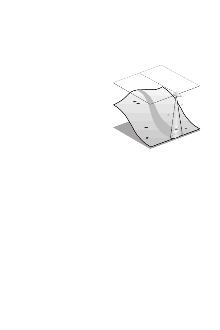
USING DEPTH OFFSET
Depth Offset adjusts the digital
depth readout to show distances
approximated from either the waterline, or the lowest point of the hull.
This is accomplished by selecting an
USING THE 100ID SERIES
INTRODUCTION
Depth Offset at Zero
USING THE 100ID SERIES
USING DEPTH OFFSET
offset value at start up which the unit
adds or subtracts to the sonar depth
measured from the location of the
transducer.
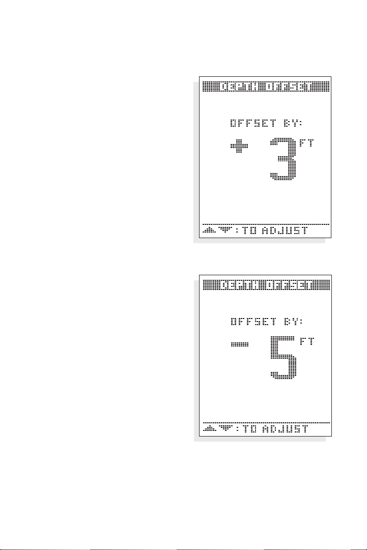
When you turn on the
100ID, the
Depth Offset screen will appear for
several seconds to allow time to select
your depth offset. Use the UP or
DOWN arrows to adjust the setting to
yield the desired depth measurement
as follows.
Selecting a positive number equal to
the vertical distance between the transducer and waterline provides a depth
reading approximated from the waterline. This “true depth” is useful for
comparing to depth soundings plotted
on navigation charts. Use caution when
operating in suspected shallow water
as many factors such as tide and waves
can effect the actual depth.
Selecting a negative number equal to
the vertical distance between the
transducer and lowest point of the hull
will give depth readouts from the
bottom of the hull, or keel.
Leaving the depth offset at zero will
have no effect on the depth readout as
measured from the transducer.
Depth Offset has a range of adjustment of -10 to +10 feet, and must be
set at start-up each time the unit is powered on.
Depth Offset to Waterline
Depth Offset to Keel
4
5
USING THE 100ID SERIES
WHAT YOU SEE ON-SCREEN
WHAT YOU SEE ON-SCREEN
The first thing you may notice about the 100ID unit is the high-resolution
LCD display. The LCD display uses super-twist technology, for maximum
viewability and is ruggedized for tough shock and vibration endurance.
The display can operate at temperatures more extreme than you are likely
to encounter.
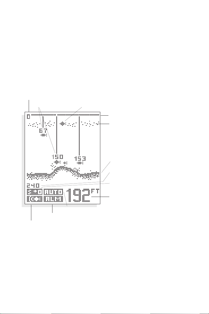
There are two basic screen layouts for the
100ID. Figure A shows the
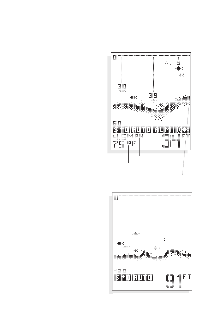
default screen layout which does not include speed and temperature readings. If you have purchased the
Speed and Temperature accessory and it is
installed, the screen layout will be slightly different as shown in Figure B.
The number of vertical pixels (picture elements or dots) in a given depth
range determines the display resolution, or ability to differentiate targets
close to the bottom or other targets. The
100ID is capable of distinguish-
ing between targets only 6" apart, and show fish within 6" of the bottom.
Figure A
Zero Line
Thermocline
Bottom Terrain
Lower Range Limit
Sensitivity Setting
Depth
Range Control Setting
Bottom Alarm Indicator
Fish Alarm Indicator
Upper Range Limit
ID+ Fish Depth Fish Symbol
6
On all screens the horizontal
line at the top of the display is
the “Zero” line. This represents the surface of the water.
The “Zero” line will always
have a gap which moves as
the screen updates. This gap
lets you know that the display
is updating even if the bottom
terrain remains the same or is
not visible on the selected
depth range. The farthest
right column of information is
the most recent information,
and it shows what is directly
under your boat.
At power-up, the
100ID
locates the bottom and
adjusts the depth range to a
setting most appropriate for that
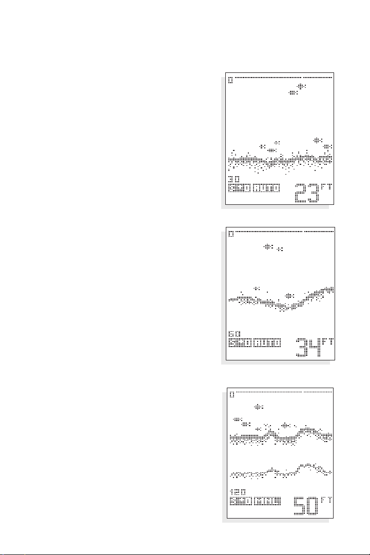
depth. The bottom will be usually
shown about
²⁄₃ of the way down
the display. The Structure ID™
depiction of the bottom will vary in
appearance depending on the
bottom terrain. If the bottom is
very hard and smooth, the bottom
depiction will be narrow and
dense. If the bottom is mud or soft
sand, the bottom depiction will be
thick and less dense. This indicates
that much of the sonar signal is
absorbed by the soft bottom. If the
bottom is rugged and varying, such
as a rocky bottom, the depiction
will be textured and vary in density.
Structure, such as submerged trees
or brush, or other objects are
clearly displayed above the solid bottom return, in varying densities of
USING THE 100ID SERIES
WHAT YOU SEE ON-SCREEN
Figure B
Boat Speed
Water Temperature
Most current information
Hard Smooth Bottom
7
pixelization. This bottom depiction is
useful in locating structure, by comparing
relative density as well as depth.
The transmitted sonar signal travels downward, and is reflected back toward the
surface by the bottom or other objects for
display on-screen. The signal does not stop
there - it is reflected downward again by the
surface of the water, and a weak “second
return” is usually visible if the depth range is
sufficient to see it. A second return is shown
in the figure below. Some users use this
second return as an indicator when setting
the sensitivity bias.
If a target is detected between the surface
and the bottom, it is displayed as a fish
symbol. Depending on the strength of the
signal reflected from the object, one of
three different size symbols is used. These
reflected signals are “normalized” for depth,
so that a small fish does not appear to be a
large fish if it is close to the boat.
Since some species of fish tend to be better
reflectors of sonar than others, the strength
of return is not always an accurate indicator of
fish size, however, typically the larger the
fish, the larger the signal return.
USING THE 100ID SERIES
WHAT YOU SEE ON-SCREEN
Soft Mud
Rocky Bottom
Second Return
 Loading...