

Humminbird Temperature/Speed Specifications
The Temperature/Speed
accessory incorporates a
paddlewheel-type speed sensor
and a water temperature probe in a high-impact plastic
housing. The module is intended for installation on the
transom, and will work well on almost any boat.
Note: If the Temperature/Speed accessory will
not work for your application, you may
exchange it, NEW and UNASSEMBLED, with
mounting hardware included, for an accessory
that is appropriate for your application - often
at very little or no charge depending on the
accessory. Call the Humminbird Customer
Resource Center (334-687-0503) for details and
pricing, or visit www.humminbird.com, Product
Support for more information.
In addition to the parts supplied, you will need a hand drill
with various bits, marine-grade silicone sealant, and a
Phillips head screwdriver.
Locate an area on the transom
of your boat 6"-8" or farther
from the transducer(s). This area
must also maintain contact with the water at high speeds.
Do not mount the module directly in front of the propeller
or outdrive, and make sure that there are no protrusions
such as ribs, rows of rivets, or transducers directly forward
of the mounting location, as these may affect the flow of
water over the paddlewheel.
Align the module on the transom so the lower edge is
flush with the hull of the boat, and mark the hole locations.
If the transom angle is excessive, a faring block may be
needed to level the paddlewheel for proper operation.
On fiberglass hulls, it is best to start with a smaller bit
and use progressively larger drill bits to reduce the chance
of chipping or flaking the outer coating. Drill two
⁹⁄₆₄"
(4 mm) mounting holes approximately
³⁄₄" (19 mm) deep.
Seal the mounting holes with marine-grade silicone
sealant, and attach the module to the transom using the
two washers and two screws provided. Hand tighten only!
INSTALLATIONBEFORE YOU
START
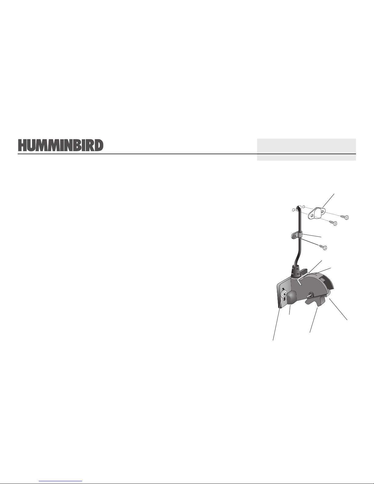
Temperature/Speed Accessory
THANK YOU
Escutcheon
Plate
Cable Clamp
Axial Clip
Wedge
Paddlewheel
Figure 1
Temperature
Probe
Wood screw
and washer
Temp/Speed
Module
pn530523-1r91219F
Thank you for choosing Humminbird, America’s #1 name in depthsounders. Humminbird has built its
reputation by manufacturing top-quality, thoroughly reliable marine equipment. Genuine Humminbird
accessories offer the opportunity to upgrade and expand the capabilities of your Humminbird product.
You may route the cable
over the top of the
transom, or drill a
⁵⁄₈" (16
mm) diameter hole in the transom directly above the
module and above the waterline to route cable
through. Use the cable clamps provided to secure
the cable to the transom of the boat. If a throughhole is used, an escutcheon plate is included to
dress the hole.
Note: On fiberglass hulls, it is best to start with a
smaller bit and use progressively larger drill bits to
reduce the chance of chipping or flaking the outer
coating.
All mounting screws require a
⁵⁄₃₂" pilot hole drilled
approximately
⁵⁄₈" deep. Additionally, seal any hole
drilled in the transom of the boat with marine-grade
silicone sealant (not included).
Route the cable to your Control Head, and install
the connector in the appropriate slot. Use the
connector designated for accessories (labeled A) on
the Control Head.
Note: Refer to your Control Head
installation guide for more information
about the quick disconnect connector
included with your Control Head.
If the connections are correct, the Control Head
will begin displaying water temperature and boat
speed information immediately. If the speed sensor
fails to read properly at high speeds, adjust the
height of the module on the transom.
You should periodically
remove the paddlewheel
from the housing and clean it to remove growth
resulting from the marine environment, as a clean
paddlewheel results in more accurate readings.
Note: This procedure should only be
performed when the boat is not running,
and is normally performed when the boat
is out of the water.
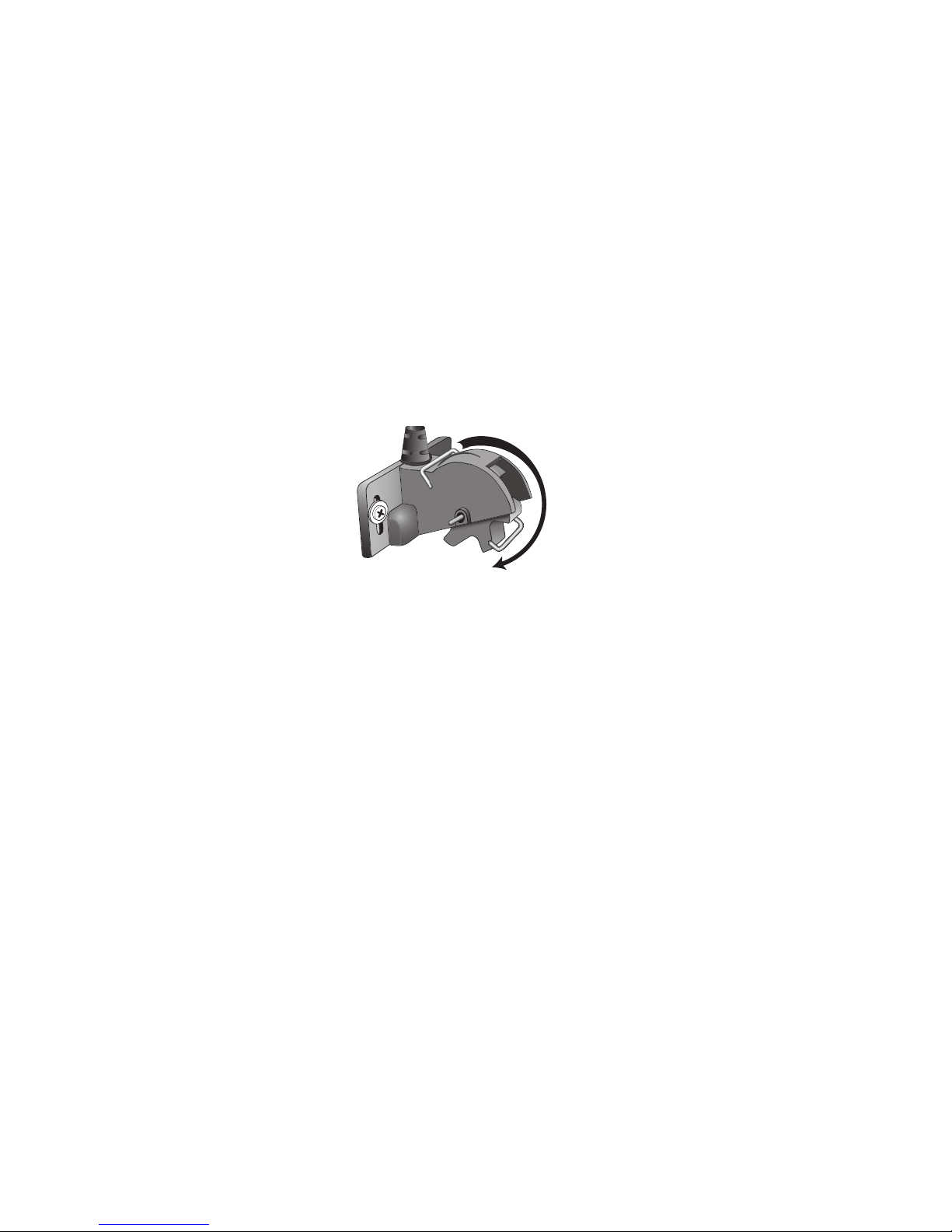
Clean the paddlewheel by disengaging the axial clip
from the housing wedge and rotating it forward.
Once you have rotated the axial clip, remove it from
the housing by sliding it away from the holes in the
housing. The paddlewheel is now removed; clean it
with a mild solution of biodegradable soap or hot
water. Clean the wheel well of debris and/or algae at
this time. Once you have cleaned the paddlewheel
you may reinsert it into the housing. Next, slide the
axial clip back into the holes, then rotate it
backwards to lock it into place with the wedge in the
housing.
Note: The Paddlewheel must be oriented so
that it is scooping the water (see Figure 1).
Your Humminbird accessory
is designed for trouble-free
operation and is backed by
a warranty. Refer to your
Humminbird Warranty Card for the specific details of
this warranty. If you have any questions contact the
Humminbird Customer Resource Center at
www.humminbird.com for Product Support and
troubleshooting guides or call:
334-687-0503
Throughout the U.S. and Canada, hours are Monday
- Friday, 8:00 a.m. to 4:30 p.m. Central Time.
Humminbird
108 Maple Lane
Eufaula, AL 36027
CUSTOMER
RESOURCE
CENTER
CLEANING
ROUTING THE
CABLE
Rotating Retaining Axial Clip to Remove
Paddlewheel.
WARNING:
Disassembly and repair of this electronic unit
should only be performed by authorized service personnel. Any
modification of the serial number or attempt to repair the
original equipment or accessories by unauthorized individuals
will void the warranty. Handling and/or opening this unit may
result in exposure to lead, in the form of solder.
WARNING: This product contains lead, a chemical
known to the State of California to cause cancer and
birth defects and other reproductive harm.
Figure 2
 Loading...