

Page 1

Page 2

TABLE OF CONTENTS
INSTALLATION PREPARATION………………………………………………………. 2
Parts Supplied……………………………………………………………………. 2
Accessories………………………………………………………………………. 2
Installation Overview……………………………………………………………. 2
Alternative Transducers and Mounting Methods…………………………….. 4
Transducer Exchange…………………………………………………………… 5
INSTALLATION………………………………………………………………………….. 6
Transom Installation…………………………………………………………….. 6
Inside the Hull Installation………………………………………………………. 10
Control Head Installation……………………………………………………….. 12
Test the Installation……………………………………………………………… 15
FEATURES AND FUNCTIONS………………………………………………………... 16
USING THE TCR ID-1………………………………………………………………….. 17
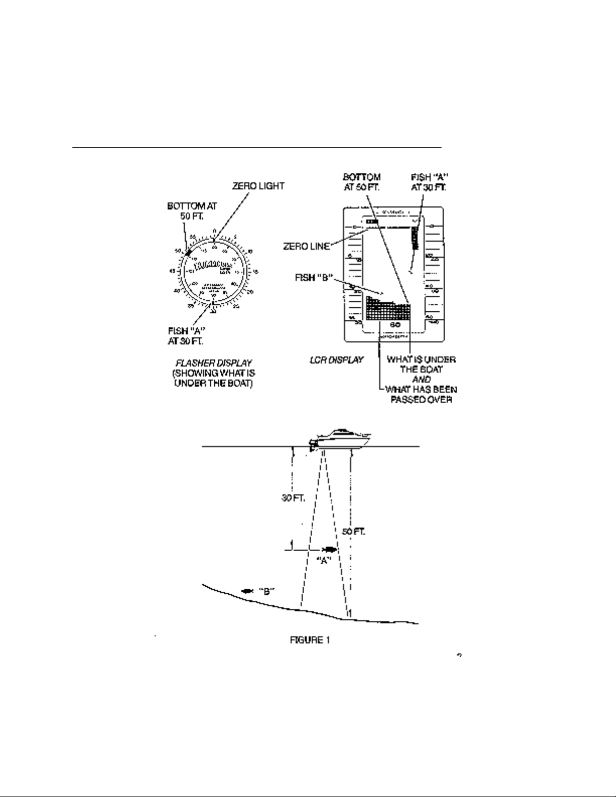
How Sonar Works……………………………………………………………….. 17
Built-In Simulator………………………………………………………………… 19
Reading the TCR ID-1 Screen………………...………………………………. 20
Functions…………………………………………………………………………. 23
SPECIFICATIONS……………………………………………………………………… 27
MAINTENANCE AND WARRANTY………………………………………………….. 28
Maintenance…………………………………………………………………….. 28
Troubleshooting…………………………………………………………………. 29
Warranty…………………………………………………………………………. 32
Service Policy…………………………………………………………………… 33
Customer Support………………………………………………………………. 34
Page 3
TRANSDUCER MOUNTING PROCEDURE
Humminbird’s high -speed transducer is supplied with your LCR. This transducer has
been designed to give good high speed readings on most all boat designs, including
aluminum.
Please carefully consider the following before in stalling your transducer.
TRANSDUCER MOUNTING OPTIONS
A. Transom Mount- The Humminbird high speed transducer allows the transducer
element to be mounted below the bottom of the boat hull keeping the transducer out
of turbulent water and insuring good high speed operation. The transducer will
Page 4
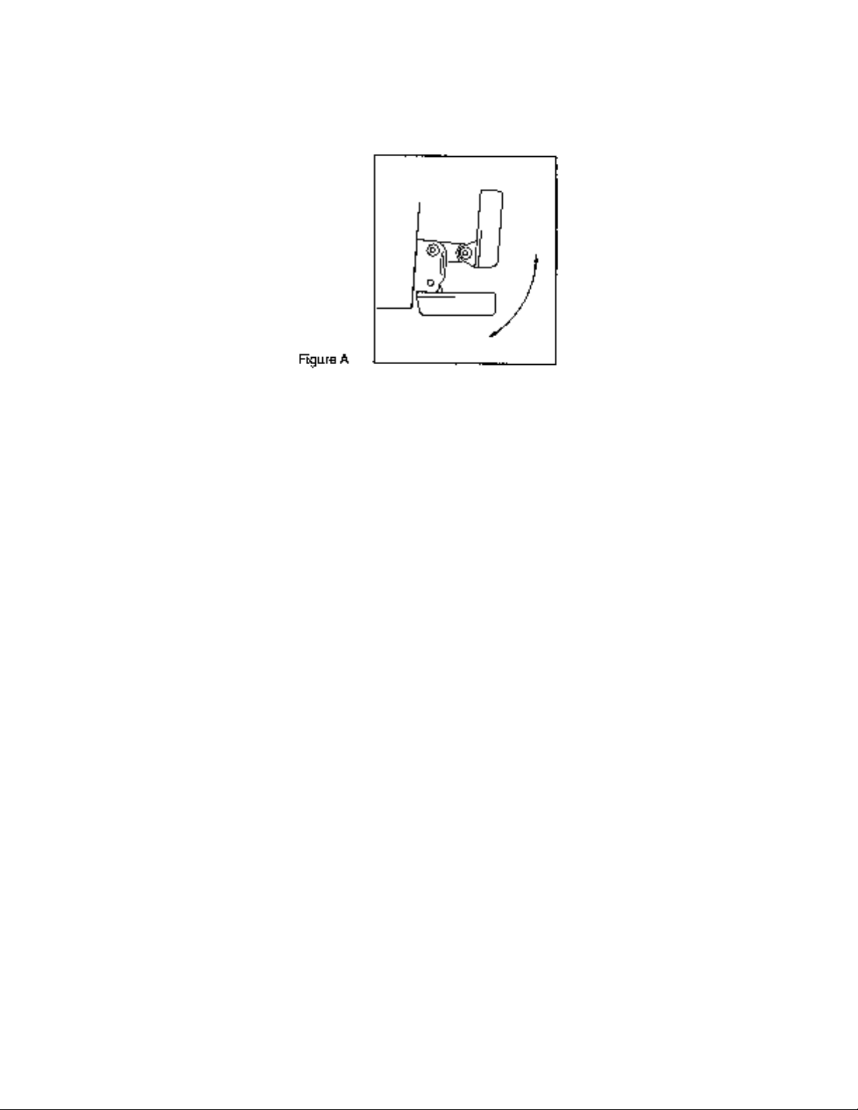
absorb the blow of any obstruction by rotating up out of the metal spring bracket
without harming the transducer, or your boat. The transducer can be re-engaged by
simply rotating the transducer down and snapping it back in place. (See Figure A)
B. Inside Hull Mount- The high speed transducer can be mounted inside the hull
(without pivot assembly) using the proper two-part epoxy, such as Humminbird’s
epoxy kit. Even though there is some loss of signal in shooting through the hull, your
LCR will perform well with this type of installation. You cannot shoot through the hull
of an aluminum boat.
C. Trolling motor Mount- This type of transducer is not supplied with your LCR. It is
designed to mount on the foot of a trolling motor. You may exchange your un-used
high speed transducer for a trolling motor transducer. Call the Humminbird
Customer Service Department.
D. Bronz Thru -Hull Mount- This transducer is not supplied with your LCR but for an
additional cost you may exchange y our un-used high speed transducer for a bronz
thru -hull. The bronz thru-hull transducer has a threaded stem which installs through
a hole drilled in the boat hull, leaving the housing exposed under the boat. This type
of installation must be used for many boats with in -board engines, because there is
no suitable location on the transom away from the noise and turbulence created by
the prop. A bronz thru -hull transducer should be installed by qualified personnel
only.
The LCR will operate well at high speeds with a properly mounted transducer.
Remember, a transducer will not work transmitting through air or through air
bubbles.
1. TRANSOM MOUNTING PROCEDURE
Step 1.
MOUNTING LOCATION- It is important that the transducer be mounted on the transom
where water flow is in constant contact with the transducer. You may wish to observe
the rear of the boat while it is moving through the water to determine the best mounting
location.
Step 2.
BRACKET INSTALLATION (Aluminum Boats)- To install the metal bracket on an
Page 5
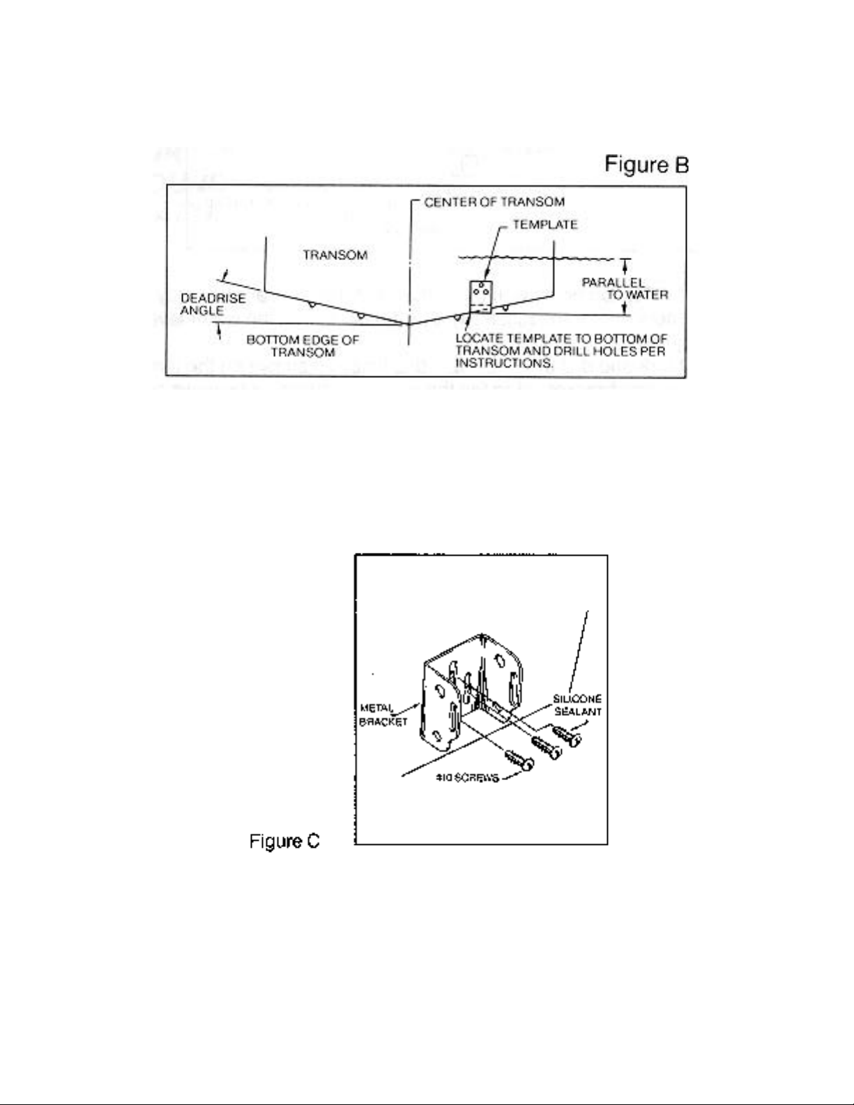
aluminum boat locate the template on the transom between rows of rivets, or ribs that
are on the bottom of the boat. Align the template so that the bottom corner of the
template nearest the center of the transom is on the bottom edge of the transom.
Once the location is determined mark and drill three 7/64” dia.. holes noted on the
template. Attach the metal bracket using three #10 self threading screws supplied. Be
sure to align holes in the center of the
Bracket slots. On some aluminum boats it may be necessary to use a wood back-up
plate. It is important to use a silicone sealant between the screwhead and bracket in
order to prevent leaking. (See Figure C)
Step 2.
BRACKET INSTALLATION (Fiberglass Boats)- If your boat has a stepped transom
located below and under the main transom, the compact transducer design allows
mounting in this area. This mounting location is recommended for good reading at very
high speeds. (See Figure D)
To install the metal bracket on a fiberglass boat, locate the template on the transom in
the same manner as for an aluminum boat. (See Figure C)
Page 6
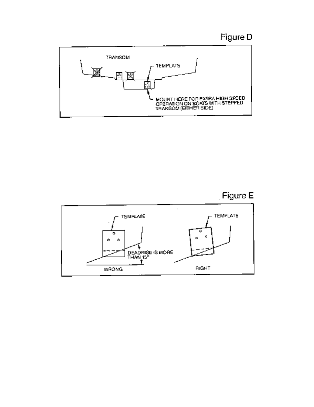
NOTE: On boats with more than 15 degree deadrise angle it may be necessary to
mount the transducer slightly off parallel with the water level. (See Figure E)
Mark and drill the three 9/64” dia. holes as shown on the template. Attach the metal
bracket using the three #10 self threading screws supplied. Be sure to align the holes so
that they are centered vertically in the three slots found in the bracket. It is important to
use a silicone sealant between the screwhead and bracket in order to prevent leaking.
Step 3.
TRANSDUCER PIVOT ASSEMBLY- Assemble the pivot to the transducer main body
using the two ¼”x5/8” allen head screws, two 3/8” tooth washers and two, ¼” square
nuts. Make sure the tooth washers are sandwiched between the transducer main body
and the pivot. The square nuts are trapped inside the pivot and will not rotate as the
allen head screws are tightened. HOWEVER, DO NOT TIGHTEN AT THIS POINT.
(See Figure F)
Page 7
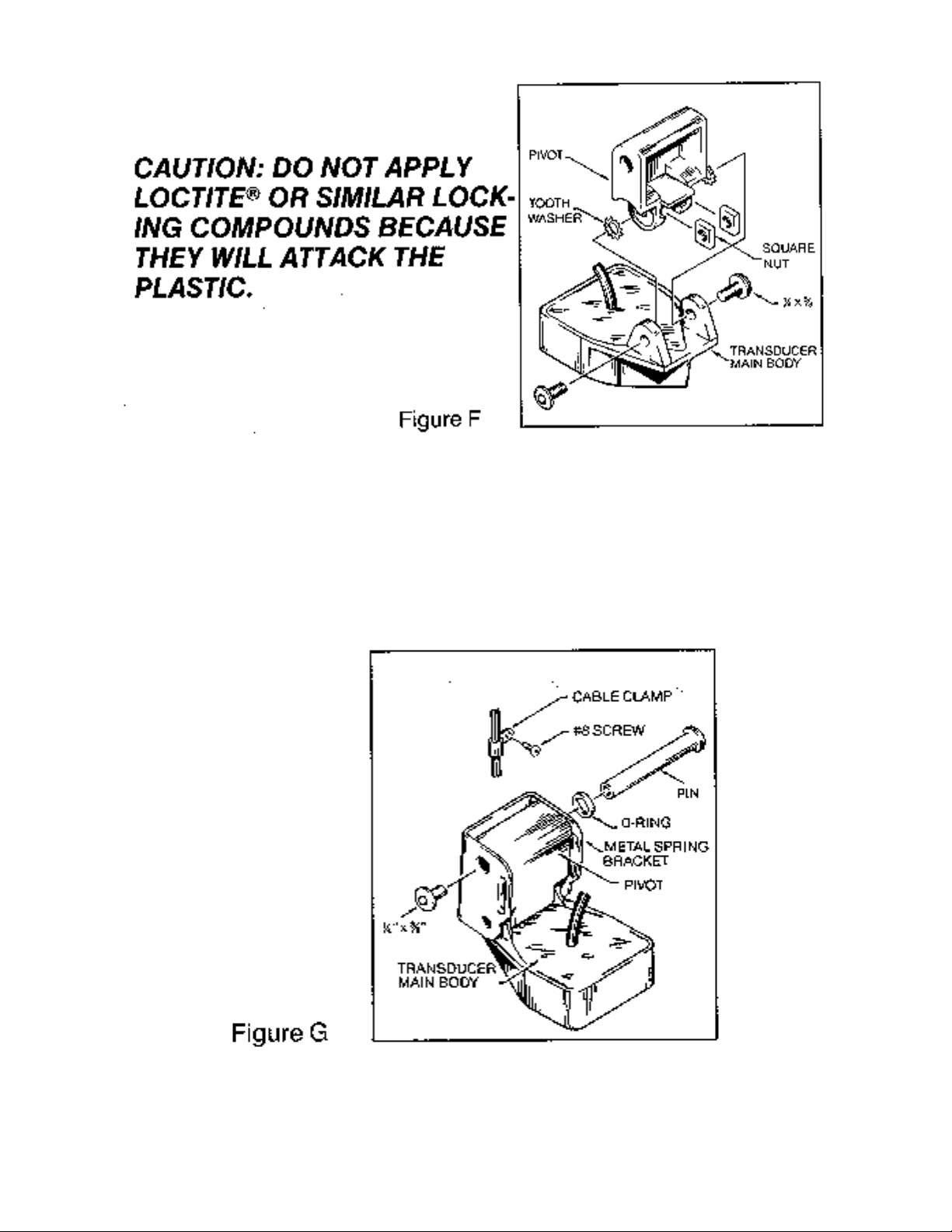
Step 4
TRANSDUCER ASSEMBLY- Insert the transducer assembly into the metal bracket
from the bottom. Push up until the holes in the plastic pivot align with the uppermost
holes in the bracket. Slide the O-ring on to the headed pin and insert it through the two
parts. Assemble by screwing the ¼”x3/8” allen head screw into the end of the pin and
tighten. (See Figure G)
Step 5
ANGLE ALLIGHMENT- Set the transducer angle so that it is parallel with the bottom of
the boat hull. Once proper alignment is achieved, tighten the two allen head screws
Page 8
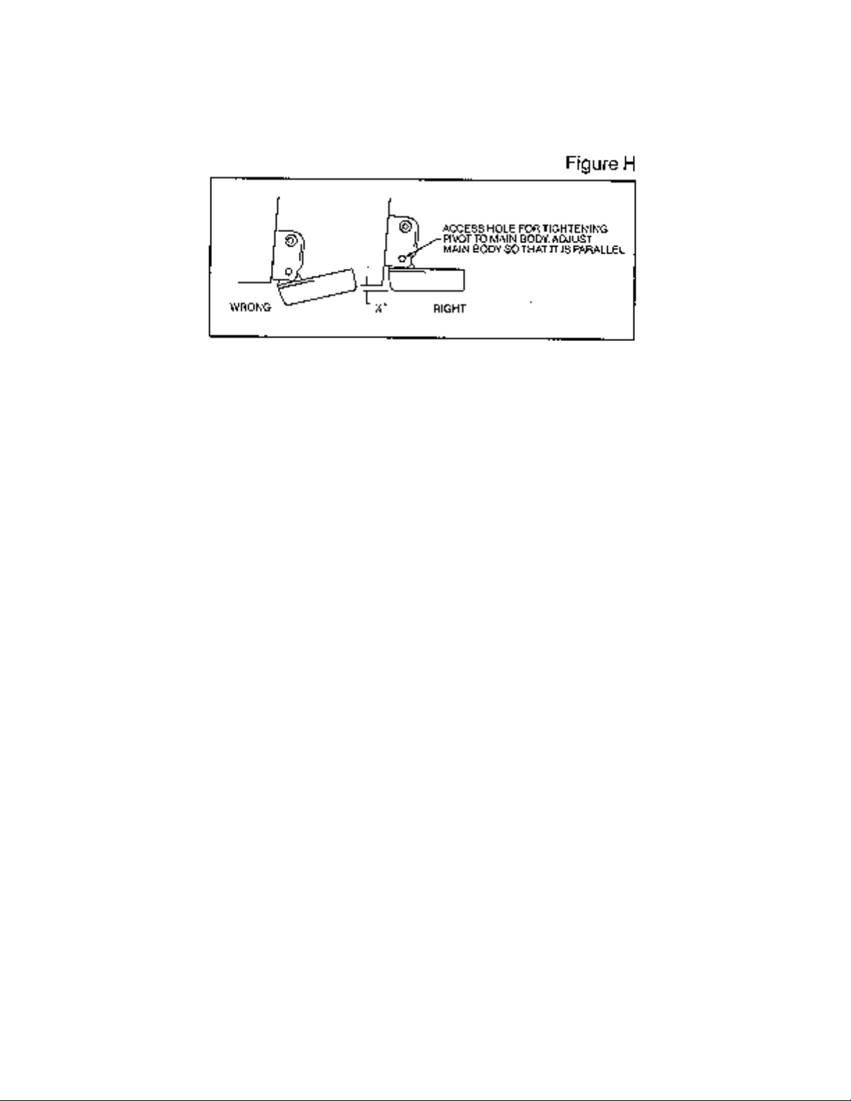
using the 5/32” allen wrench provided. The screws are visible through the access holes
on each side of the metal bracket. Check to make sure the transducer main body is
rigidly fastened to the pivot. (See Figure H)
Step 6
CHECK POSITION OF TRANSDUCER - At this point, check to see that the bottom of
the transducer is a minimum of ¼” below the bottom of the transom. (However, as noted
in STEP 2, the top of the transducer cannot fall below the bottom of the transom). If it is
not, remove the transducer assembly from the metal bracket by removing the pin
installed during STEP 3. Loosen the metal bracket mounting screws, re-position the
bracket utilizing it’s slotted holes, tighten and re-assemble. It may be necessary to
replace the silicone sealant after this adjustment is made.
NOTE: It may be necessary to make several high speed runs to adjust transducer
either UP/DOWN or to re-adjust the angle to achieve optimum results.
Step 7
CABLE CLAMPS- Install cable clamps as necessary by drilling a 1/8” dia. hole for the #
8 screw supplied.
2. INSIDE HULL MOUNTING PROCEDURE
Warning: In order to achieve proper results with this type installation, it is important that
the transducer be mounted by someone familiar with the use of two part epoxy
adhesives. For this reason, Techsonic Industries, Inc. will not be responsible for any
damage due to the mounting of your transducer in this manner.
NOTE: An Epoxy Kit (Part N. EPK) is available from Humminbird. This Epoxy Kit has
been formulated for Inside Hull Transducer Installation.
1. Select as flat an area as possible near the aft end and center of boat where the hull
is thin and not double. If the bottom has a runner down the center of boat, select an
area to one side of the runner, but as close to the runner as possible.
2. Clean the inside of the boat with lacquer thinner in the area transducer is to be
mounted. Outside of boat in this area should also be cleaned. (Not with lacquer
thinner).
3. Put approximately one inch of water in the bottom of the boat.
Page 9

4. Put transducer in the water. The bottom of the transducer should be in a flat area
and should be in good contact with the bottom of the boat.
5. Operate the LCR with the boat operating at high speed. The transducer may have to
be moved in order to find an area where satisfactory operation is observed.
6. When an area is found that produces satisfactory operation, mark the location of the
transducer.
7. Remove the water and transducer and clean the marked area and the bottom of the
transducer thoroughly.
8. Using the Humminbird Epoxy Kit or equivalent, mix an ample amount of epoxy
without causing it to bubble and pour it in the area the transducer is to be mounted.
The puddle should be larger than the bottom of the transducer.
9. Coat the bottom of the transducer with epoxy, then put it in the center of the puddle
and push down on the transducer while moving it around in a circular motion. This
forces out any air bubbles that may be trapped between the bottom of the transducer
and the hull of the boat.
10. Let epoxy cure then the transducer is ready to operate. No water is now required in
the bottom of the boat and gas and oil that is spilled inside of the boat will not
degrade performance as it will if the transducer is placed only in water.
CAUTION: Do not use the silicone seal or any soft adhesive to bond the transducer
to the hull. This will reduce the sensitivity of the unit.
CAUTIONS
1. Occasionally the “eye“ of your transducer may become dirty from storage or from
contact with oils present in boats or marina environments. (Oil will cause the “eye” to
lose the intimate contact with the water which is necessary for efficient operation.)
The “eye” may be cleaned with liquid detergent.
2. Improper installation of the transducer can alter the efficiency and accuracy of the
entire system.
3. If your boat of transducer is out of the water for a period of time, it may take a short
period of time for the transducer to become thoroughly “wetted” when returned to the
water. Also, re-entry may cause turbulence, which will create air bubbles in the “eye”
of the transducer. The bubbles will disappear in a short time or can be removed by
rubbing the transducer “eye” with your fingers while the transducer is in the water.
4. If your instrument should fail to function , be sure to check all the electrical
connections before removing the transducer or calling a serviceman.
5. Inspect your transducer cable and make sure that it has not been cut or damaged to
the point where it will affect the performance of the transducer. A slight nick or cut,
exposing the outer cable, can be repaired by wrapping with electrical tape. A
transducer can be damaged if the inner cable and outer cable are allowed to make
contact. Such a problem can sometimes be corrected by properly splicing the
coaxial cable. This should only be attempted by a qualified service technician.
6. If your LCR is not working properly and you suspect the problem might be in your
transducer, we would recommend you borrow a unit from a friend and try it on your
boat. If the symptoms are the same, you can almost be certain that the problem is in
the transducer.
Page 10
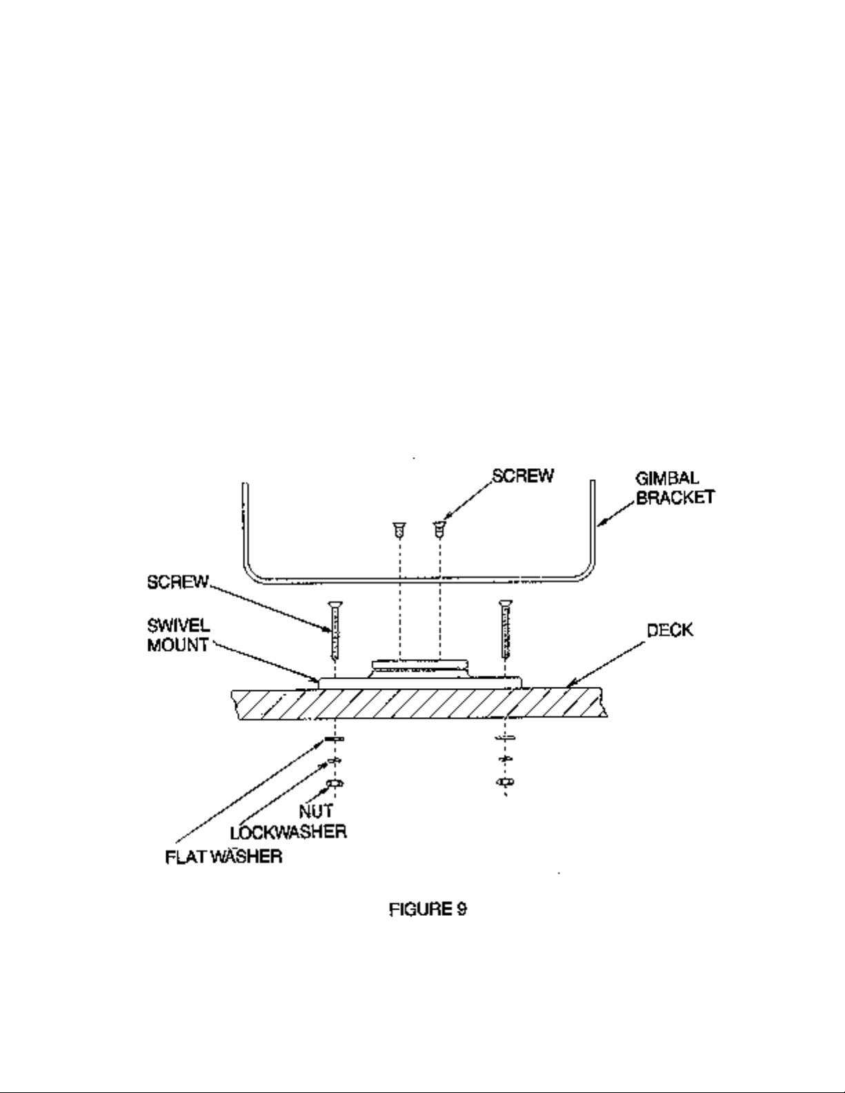
INSTALLING THE LCR
The LCR should be mounted on a flat, solid surface for maximum stability. The low
profile swivel mount has four holes drilled in the base. It is recommended that all four
holes be used.
Position the swivel base and drill four ¼” diameter holes. Note: The LCR hole pattern Is
the same as for all Humminbird flasher units. Use hardware provided to mount this base
to the boat.
Next place the gimbal bracket on the swivel base and attach with four small machine
screws, provided.
Place the LCR in the gimbal mount and make certain the rubber washers provided are
placed between the unit and the gimbal bracket Important: Note which side of the
gimbal faces forward. (Slots on gimbal bracket go towards rear). Also, rubber washer
must be located between the unit and the gimbal bracket.
Install the mounting knobs and tighten snugly. The unit can now be swiveled and tilted
to any desired position.
Page 11

cannot be rotated.
OTHER MOUNTING OPTIONS
1. The LCR gimbal bracket can also be mounted on the SM -4, quick disconnect swivel
mount.
2. The LCR gimbal bracket can also be mounted directly to the dash without the swivel
mount, however, this method is not recommended since the unit
INSTALLING THE CABLES
Your LCR comes equipped with Humminbird’s new Angle-Lock power and transducer
connectors. The power connector is identified with the letter P on the back of the plug.
It plugs into the outlet on the back of the unit marked “Power”. The transducer connector
is identified with the letter T and plugs into the outlet on the back of the unit marked
Page 12

“Transducer”. Note: An adapter (AD-4) is available to allow use of an old waterproof
(BNC) transducer with the LCR, but be sure that the transducer is a 16degree. A 32degree transducer cannot be used.
A 11/8” hole must be drilled to pull through the transducer connector. After drilling the
hole, pull the transducer connector up through the hole. If you are installing two units,
both transducer connectors can be pulled through this 1 1/8” inch hole. Next, push the
power cable wires down through the hole. A hole cover has been provided which will
dress and hold the wires. Install the hole cover after determining the necessary wire
length from the hole.
The power cable has a red lead to the positive (+) post and the black lead to the
negative (-) post. Install a 1 amp fuse between the red cable and positive post of your
12-volt battery.
If a fuse panel is available, we recommend wiring the power cable into the fuse panel.
Note: The LCR must be fused separately from any other accessory.
Your Angle-Lock connectors can only be plugged in one way. Position the connector so
the letter P or T can be read and the 90 degree bend is pointed downward. Push the
connector in as far as it will go. Turn the positive locking ring as far as it will go
clockwise until you feel it lock. Locking ring as far as it will go clockwise until you feel it
lock. Your connector is now locked into place.
Note: For easy access to the connectors, simply loosen the mounting knobs and tilt your
LCR forward. The connectors are now in full view and easy to plug or unplug.
Page 13

INSTALLATION
TEST THE INSTALLATION
TEST THE INSTALLATION
Testing should be performed with the boat in the water, however you can initially
confirm basic operation with the boat trailered.
Press POWER once to turn the unit on. There will be an audible chirp when any button
is pressed to confirm the button press. If the unit does not power-up, ensure the unit is
fully seated on the mount and that power is available.
The first screen provides four options: Start-up, Options, Simulator, and Diagnostic. A
message at the bottom of the screen indicates the transducer connection. If no
transducer is detected (or one is not connected), the message will indicate this and the
unit will go into simulator after the initial screen times out.
Note: the transducer must be submerged in water for reliable transducer
detection.
If a transducer is detected, the unit will enter “Start Up” or normal operation unless you
choose another option. If you do not press any button before the timer reaches “0”, the
normal operation screen is displayed. If the boat is in water, sonar data appears.
If the bottom is visible on screen with a digital depth readout, the unit is working
properly. Ensure the boat is in water greater than 2’ but less than the depth
capability of the unit and the transducer is fully submerged. Remember the sonar signal
cannot pass through air.
If the unit is working properly gradually increase the boat speed to test high -speed
performance. If the unit -functions well at low speeds but begins to skip or miss the
bottom at higher speeds, the transducer requires adjustment. Refer to the appropriate
transducer installation section for more detail.
Note: it is often necessary to make several incremental transducer adjustments
before optimum high-speed performance is achieved.
Important: For Transom Mount transducer installations, install the third mounting screw
after the final transducer adjustments.
Humminbird • 3 Humminbird Lane • Eufaula, Alabama 36027
Page 14

USING THE TCR ID-1
FEATURES AND FUNCTIONS
Page 15

USING THE TCR ID-1
HOW SONAR WORKS
HOW SONAR WORKS
Humminbird depth sounders work on the basic principles of sonar. An electronic signal
generated in the unit is changed to an ultrasonic signal by the transducer or Sensor,
which sends the signal toward the bottom. The signal travels downward until it strikes
either the bottom or an object above the bottom. Then, signals or echoes bounce back
to the Sensor, which receives them and changes them back to electronic signals that
can be displayed on the unit’s screen.
Why 455KHz?
Deepwater depth sounders have long used 50KHz for best deepwater performance, but
they suffer with poor definition. Shallow -water units use a higher frequeney 200KHz
system for better target separation and detail. But TCR technology takes high definition
to a new level with its exclusive 455KHz operation.
What does that mean to the fisherman? TCRs have twice the frequency, three times the
power (1600 watts, peak to peak) and twice the detail of other units. You can clearly
separate fish from the bottom and from structure, and you can see individual fish in a
way that ordinary depth sounders just can’t show them. Quite simply you see more fish
with more detail!
WHAT IS A HIGH-DEFINITION DEPTH SOUNDER?
The TCR ID-I features our exclusive 455KHz high -definition performance system - twice
the frequency, three times the power (1600 walls peak to peak) and twice the detail of
other units.
Page 16

USING THE TCR ID-1
HOW SONAR WORKS
Compact, High-Definition Sensor.
To send and receive this higher-frequency signal, we developed a new High -Definition
Sensor. You can immediately see the difference between our 455KHz Sensor and older
200KHz transducers. This unique new Sensor makes bulky low -definition transducers a
thing of the past.
Our new Sensor is so compact, it’s a snap to install. It’s designed for superior high speed performance, and because of its small size you'll have less problem with drag,
turbulence, or rooster-tails. This new Sensor is actually less likely to be damaged by
debris, yet performs with all the accuracy you expect from Humminbird.
Page 17

USING THE TCR ID-1
BUILT-IN SIMULATOR
BUILT-IN SIMULATOR
To help you learn to use your new unit, Humminbird has built a simulator into the TCR
ID-1.The simulator will display a typical underwater scene, and allow you to use the
controls for practice.
Activating the simulator is easy - with the unit turned off, hold down the power button for
about 2 seconds, until a chirping sound begins. When you release the button, the builtin simulat or will be on and ready for your practice session. Turning your unit off and
back on again will disengage the simulator, for operating the TCR ID-1 in actual
conditions.
NOTE: The built-in simulator will allow you to practice adjusting the sensitivity,
but your adjustments will not change the readings being displayed on the screen.
Page 18

USING THE TCR ID-1
READING THE TCR ID-1 SCREEN
READING THE TCR ID-1 SCREEN
Your TCR has a liquid crystal display, or LCD. The liquid crystal material in the display
aligns it self to either block light or let light pass through. This blocking of light creates
images on the screen. Since the display depends on light to form its images, increasing
the light source makes it easier to see. This is why your TCR can be seen so well in
bright, direct sunlight.
You will also notice that the display can be seen better at certain angles. The TCR
mounting system has been designed for tilting and pivoting so that you can easily
maintain a good angle for viewing. Another characteristic of the display is that some
polarized glasses can affect your view by causing a rainbow or prism to appear. This
can be im proved by slightly tilting the unit.
Fish Identification
The TCR ID-1 uses Humminbird’s exclusive double-layer LCD. Ordinary LCD unit s have
2 colors - black and white. But the TCR ID-1 adds a third color - red - by using a second
layer on the display. This double-layer display gives you more information than ordinary
black and white units:
1. Objects close to the bottom are displayed in red. The bottom and any structure
attached to it are displayed in black. The microcomputer within the TCR ID-1 will detect
objects close to the bottom and display them in red no matter what depth range you're
in. This is especially helpful if you're bottom-fishing
2. Stronger signals are displayed as a black dot behind a red dot. The TCR ID-1's
microcomputer also helps you identify stronger signals, such as those from larger fish,
because they are displayed as a black dot behind a red dot. It's easy to separate them
from the weaker returns displayed in red only.
Page 19

USING THE TCR ID-1
READING THE TCR ID-1 SCREEN
Total Screen Update
Humminbird’s exclusive Total Screen Update instantly updates the entire TCR screen to
include new information each time a function is changed no waiting for the changes to
“march” onto the screen. This feature is valuable in 2 ways:
1. Changing depth ranges. When the depth range changes to a deeper or shallower
scale, the entire screen changes to display the new depth scale. For ex ample, if you’re
in the 0-60’ scale and it changes to the 0-30’ scale, the entire screen will look as if you
had been in the 0-30’ range all along.
2. Using zoom and bottom-lock. Through Pixel Memory Capacity, the memory in the
TCR ID-1 stores readings in much finer detail than is displayed in the “regular” mode.
So when you activate the zoom or bottom-lock functions, the entire screen changes to
display the up-close detail that is stored in memory. Then when you turn on the zoom or
bottom-lock, the whole screen will change back to the full depth scale.
Page 20

USING THE TCR ID-1
READING THE TCR ID-1 SCREEN
Of course, the best way to learn to read your TCR ID-1 is to use it, especially in familiar
locations. If you know what's underwater and can see it display ed on the screen, then
you're on your way to being an experienced TCR user.
Page 21

USING THE TCR ID-1
OPERATING THE TCR ID-1
OPERATING THE TCR ID-1
Your new TCR ID-1 offers unique automatic features, as well as many adjustable ones.
If you're learning to operate the TCR ID-1 with its simulator, follow the directions listed
at “Built-In Simulator” on page 16, and then come back to this page. If you’re learning to
use your TCR ID-1 using actual on -the-water readings, proceed with the following
instructions.
Power:
Pressing this button once turns the TCR ID-1 on. Pressing it once again
turns it off. When the unit is turned off, holding this button down for about 2
seconds activates the built-in simulator.
Stop:
By pressing this button once, you can stop or “freeze” the display. Pressing
the button once again re-starts the display at its previous speed setting.
Light:
The TCR ID-1 features a 2-level backlight that evenly lights up the display
from behind the screen. Pressing the “light” button once gives you a soft
glow that is ideal for night fishing because it won’t interfere with your night
vision. Press the button again for a brighter light, making the display easy to
read at dusk when it can be harder to see. Pressing the button a third time
turns off the backIight.
Select System:
The TCR ID-1 Select System commands an amazing number of functions with only four
buttons: Select, Up and Down arrows, and On/Off.
When you press the Select button, each function appears in a block on the screen with
easy-to-understand instructions for using the function. You use the Up and Down
arrows and the On/Off button to adjust the functions. Then, the Instructions disappear,
returning the display to its full screen reading.
Select System functions are “active”; that is, the last function displayed on the screen
can be adjusted without pressing the select button again. This is valuable in 2 ways.
Example 1: Readjusting a function.
If bottom alarm was the last function used, you can adjust it again by pressing one of
the arrow buttons or the On/Off button.
Page 22

USING THE TCR ID-1
OPERATING THE TCR ID-1
Example 2: Often-used function.
If you think you'll be using zoom often, you can go to the zoom function, let the
instructions disappear, and then activate the zoom when you need it simply by pressing
On/Off.
The following describes the functions and how to use them,
in order of appearance after you turn the unit on.
1. Sensitivity
Automatic setting: on, "0" or normal
As conditions change, the computer will automatically in -
crease or decrease the sensitivity setting. You can man ually
increase or decrease the automatic setting from a range of
“+5” to “-5.” This level will maintain itself as long as you
have the unit on, automatically, as a result of the TCR's
Sensitivity Bias feature. For example, if you set the
sensitivity at “+2,” the sensitivity will remain 2 settings
higher than the normal automatic settings until you turn the
TCR off.
2. Bottom Alarm
Automatic setting: off
Use the On/Off button to activate the alarm, and the alarm
cursor appears on the screen. Then use the arrow keys to
adjust the depth at which the alarm will sound. You'll hear a
continuous chirping sound when the bottom is within the
area that you've defined with the alarm cursor. This is a
great feature to use to alert you to shallow
water, or to maintain your position over structure.
3. Fish Alarm
Automatic setting: off
The fish alarm is easily activated by pressing the On/Off button. This 2-level alarm can
be set to sound for all fish, or to ign ore weaker signals and alarm only for stronger
signals, such as those from larger fish. You can also adjust the volume of the fish alarm.
The controls for this function are a little different. Pressing the Up arrow lets you switch
between alarms for all fish and large fish. The Down arrow controls volume of the alarm.
Page 23

USING THE TCR ID-1
OPERATING THE TCR ID-1
Once the instructions have disappeared from the screen, it's easy to tell which alarm
you have activated - the alarm for all fish shows both small and large fish symbols at the
bottom of the screen, while the “large only” alarm displays only a large fish symbol.
4. Zoom
Automatic setting: off
When zoom is activated by pressing On/Off, it creates a “window” of expanded, up-
close information. This win dow is marked by a cursor at the right of the screen and can
be moved up or down with the arrow buttons. The exact depths of the upper and lower
limits of the window are displayed as depth scales while you are in zoom.
The size of the zoom window changes as the depth range changes. The window
displays 7½ feet of up-close readings in the 15’ and 30’ ranges, and 15 feet in the 60'
and 120’ ranges. Keep in mind that, using your arrow buttons,
you can move the zoom window while the zoom is activated,
without having to press Select again.
5. Bottom-Lock
Automatic setting: off
You can easily turn on the bottom-lock with the On/Off button.
When on, this function shows up-close zoom readings in
reference to the bottom. The size of the zoom window
depends on the depth range - 7½ feet in the 15' and 30'
ranges, and 15 feet in the 60’ and 120' ranges. The zoom
window will automatically move up or down to stay on the
bottom, with the cursor showing you the portion of the total
depth range that is being displayed. This is an ideal feature for
finding structure or locating fish near the bottom.
6. Display Speed
Automatic setting: one setting less than highest speed
The speed at which the TCR display moves depends on the
display speed setting, and it is easily changed by pressing the
Up arrow for a faster setting and the Down arrow for a slower
setting. Generally speaking, the higher speed settings allow
faster updates while slower display speeds provide more
information.
Page 24

USING THE TCR ID-1
OPERATING THE TCR ID-1
7. Depth Range
Automatic setting: on
The TCR automatically finds the bottom and then sets and displays the ideal depth
range when you turn the unit on. If you choose to leave the auto range change on, the
bottom will remain "blacked in" for easy -to-understand readings, and the depth ranges
will change automatically.
Or, you can turn the auto change off, allowing you to change the depth range manually.
In this mode, the bot tom is not blacked in. This lets you see a double bottom echo,
which is preferred by some fishermen because the width of the second echo can
indicate bottom texture (see “Reading The TCR ID-I Screen” for details on using the
double echo).
Page 25

SPECIFICATIONS
Operating Frequency 455KHz
Power Requirement 12 volts
Power Cable Length 11½’
Sensor (standard) SHS-6-16 High -Definition, high-speed
Sensor Cone Angle 16 degrees
Sensor Cable Length 20’
Depth Ranges 0-15’, 0-30’, 0-60’, 0-120’
Zoom Ranges 7½’, 15’
Mounting (standard) All-in-One Mounting & Connector System
Unit Construction High-impact polycarbonate case
Dimensions 6 ½” W X 6 ¾”H X 1 ½”D
Display liquid crystal
Viewing Area 3” W X 4" H
Matrix Configuration 48 x 75 pixels
Page 26

MAINTENANCE AND WARRANTY
MAINTENANCE
MAINTENANCE
Your Humminbird fishfinder is designed to provide years of trouble free operation with
virtually no maintenance. Follow these simple procedures to ensure your Humminbird
continues to deliver top performance.
• If the unit comes into contact with salt spray simply wipe the affected surfaces with a
cloth dampened in fresh water. Do not use a chemical glass cleaner on the lens.
Chemicals in the solution may cause cracking in the lens of the unit.
• When cleaning the LCD protective lens, use a chamois and non -abrasive, mild
cleaner. Do not wipe while dirt or grease is on the lens. Be careful to avoid
scratching the lens.
• If your boat remains in the water for long periods of time, algae and other marine
growth can reduce the effectiveness of the transducer. Periodically clean the face of
the transducer with liquid detergen t. Pivoting the transducer up in the bracket may
allow better access for inspection or cleaning.
• If your boat remains out of the water for a long period of time, it may take some time
to wet the transducer when returned to the water. Small air bubbles can climb to the
surface of the transducer and interfere with proper operation. These bubbles
dissipate with time, or you can wipe the face of the transducer with your fingers after
the transducer is in the water.
• Never leave the fishfinder in a closed car or trunk - the extremely high temperatures
generated in hot weather can damage the electronics.
Page 27

MAINTENANCE AND WARRANTY
TROUBLESHOOTING
TROUBLESHOOTING
Do not attempt to repair the fishfinder yourself. There are no user serviceable parts
inside, and special tools and techniques are required for reassembly to ensure the
waterproof integrity of the housing. Repairs should be performed only by authorized
Humminbird technicians.
Many requests for repair received by Humminbird involve units that do not actually reed
repair. These units are returned “no problem found.” If you have a problem with your
Humminbird, use the following troubleshooting guide before calling Customer Support
or sending your unit in for repair. Your Humminbird fishfinder contains several tools that
can aid in determining if there is a problem and how to isolate and repair the problem in
many cases.
1. Nothing happens when I turn the unit on.
Check the power cable connection at both ends. Be sure the cable is connected
correctly to a reliable power source - red lead to positive, black lead to negative or
ground. Ensure the power available at the mount is between 10 and 20 VDC. If the unit
is wired through a fuse panel, ensure the panel is powered. Often accessory fuse
panels are controlled by a separate switch or the ignition switch. Also, often a fuse can
appear to be good when in fact it is not. Check the fuse with a tester or replace it with a
fuse known to be good.
Check the power connection to the unit. It is possible to force the pow er cable connector
into the cable holder incorrectly. If the connector is reversed, the unit will not work.
Examine the contacts on the back of the unit to ensure there is no corrosion. Finally,
ensure the unit is firmly seated on the mount. The electrical contacts are not made until
the unit is fully seated.
Ensure the metal cable retainer is properly installed in the mount. If not, the power
connected may push out when the unit is put on the mount.
2. There is no transducer detected.
Most Humminbird fishfinders have the ability to detect and identify that a transducer is
connected. If at power up, a message indicates "transducer not connected,” only
simulator operation is possible. First, ensure that an appropriate transducer connector is
positioned correctly in the connector holder, and that the unit is fully seated on the
mount. Your Humminbird fishfinder will work only with an appropriate transducer; check
the accessory guide for compatibility.
Page 28

MAINTENANCE AND WARRANTY
TROUBLESHOOTING
Second, inspect the transducer cable from end to end for breaks, kinks, or cuts in the
outer casing of the cable. Also ensure the transducer is fully submerged in water. If the
transducer is connected to the unit through a switch, temporarily connect it directly to
the unit and try again. If none of these items identifies an obvious problem, the
transducer itself is probably the problem. Be sure to include the transducer if returning
the unit for repair.
3. There is no bottom reading visible on the display.
There are a number of possible causes for this condition. If the loss of bottom
information occurs only at high boat speeds, the transducer needs adjusting. If the
digital depth readout is working but there is no bottom visible on -screen, it is possible
the depth range has been adjusted manually to a range lower than what is needed to
display the bottom. Also, in very deep water, it may be necessary to manually increase
the sensitivity setting to maintain a graphic depiction of the bottom.
If you are using a transducer sw itch to connect two transducers to the unit, ensure the
switch is in the correct position to connect a transducer that is in water. (If a trolling
motor transducer is selected and the trolling motor is out of water, no sonar information
appears.)
It none of the above solve the problem, inspect the transducer cable from end to end for
breaks, kinks, or cuts in the outer casing of the cable. If the transducer is connected to
the unit through a switch, temporarily connect it directly to the unit and try again . If none
of these items identifies an obvious problem, the transducer itself may be the problem.
Be sure to include the transducer if returning the unit for repair.
4. When in very shallow water, I get gaps in the bottom reading and inconsistent
digital dep th indication.
Your Humminbird fishfinder will work reliably in water 2’ (.6m) or deeper. The depth is
measured from the transducer, not necessarily from the surface.
Page 29

MAINTENANCE AND WARRANTY
TROUBLESHOOTING
5. The unit comes on before I press POWER, and won't turn off.
Check the transducer cable. If the outer jacket of the cable has been cut and the cable
is in contact with bare metal, you need to repair the cut with electrical tape. If there is no
problem with the cable, disconnect the transducer from the unit and see if the problem
is corrected, to confirm the source of the problem.
6. I get gaps in the reading at high speeds.
Your transducer needs adjusting. If the transducer is transom-mounted, there are two
adjustments available to you - height and ru nning angle. Make small adjustments and
run the boat at high speeds to determine the effect. It may take several tries to optimize
high speed operation. This can also be a result of air or turbulence in the transducer
location caused by rivets, ribs, etc.
7. My unit loses power at high speeds.
Most Humminbird fishfinders have over-voltage protection that turns the unit off when
input voltage exceeds 20 VDC. Some outboard motors do not effectively regulate the
power output of the engine's alternator and can produce voltage in excess of 20 volts
when running at high RPMs. Your fishfinder displays input voltage in the Diagnostic
screen. Use this readout to determine if the voltage exceeds 20 VDC.
8. The screen begins to fadeout. Images are not as sharp as normal.
Check the input voltage using Diagnostic. The fishfinder will not operate on input
voltages below 10 VDC.
9. The display shows many black dots at high speeds and high sensitivity
settings.
You are seeing noise or interference caused by one of several sources. Noise can be
caused by other electronic devices. Turn off any nearby electronics and see if the
problem goes away. Noise can also be caused by the engine. If engine noise is causing
the interference, the problem will intensify at higher RPMs. Increase the engine speed
with the boat stationary to isolate this cause. Propeller cavitation can appear as noise
on-screen. If the transducer is mounted too close to the propeller, the turbulence
generated can interfere with the sonar signal. Ensure that the tran sducer is mounted at
least 15" (38cm) from the prop.
Page 30

MAINTENANCE AND WARRANTY
WARRANTY
HUMMINBIRD ONE YEAR FULL WARRANTY
First year repairs (from original date of purchase) on your Humminbird fishfinder are
absolutely free. This does not include physical damage to the unit or its accessory
items. Any modification or attempt to repair the original equipment or accessories by
unauthorized individuals will void the warranty. Return the warranty registration card
and retain your bill of sale for warranty verification. Accessories not manufactured under
the Humminbird trade name are not covered by our warranty. The customer is
responsible for shipping charges to Humminbird. Humminbird will provide ground
UPS or Parcel Post shipping back to the customer free of charge. This warranty applies
to the original purchaser only.
This warranty is in lieu of all other warranties expressed or implied and no
representatives or persons are authorized to provide for any other liability in connection
with the sale of our products. Humminbird reserves the right to perform modifications or
improvement on its products without incurring the obligation to install the changes on
units previously manufactured, sold, delivered, or serviced.
THIS IS A FULL WARRANTY AS DEFINED BY THE FEDERAL WARRANTY ACT
EFFECTIVE JULY 4 1975.
Page 31

MAINTENANCE AND WARRANTY
SERVICE POLICY
SERVICE POLICY
This Service Policy is valid in the United States only. This applies to Humminbird units
returned to our factory in Eufaula, Alabama, and is subject to change without notice.
All repair work is performed by factory -trained technicians to meet exacting factory
specifications. Factory serviced units go through the same rigorous testing and quality
control inspection as new production units.
Even though you'll probably never need to take advantage of our incredible service
guarantee, it’s good to know that we back our unit this well. We do it because you
deserve the best. We will make every effort to repair your unit within three working days
from the receipt of your unit. This does not include shipping time to and from our factory.
Units received on Friday are usually shipped by Wednesday, units received Monday are
usually shipped by Thursday, etc.
We reserve the right to deem any product unserviceable when replacement parts are no
longer reasonably available or impossible to obtain.
After the original warranty period, a standard flat rate service charge will be assessed
for each repair (physical damage and missing parts are not included). Please call our
Customer Support Department to verify the service charge for your unit.
The standard service charge includes UPS or Parcel Post freight only. If charges are
not prepaid, the unit will be returned COD. If you are experiencing problems related to
bottom or depth readings please send your transducer along with your unit when
sending for repair.
Page 32

MAINTENANCE AND WARRANTY
CUSTOMER SUPPORT
CUSTOMER SUPPORT
If you have any questions, call our
Humminbird Customer Support Hotline: 1-334-687-0503
Throughout the U.S. and Canada, hours are Monday -Friday, 8:00 a.m. to 5:00 p.m.
Central time.
If after reading “Troubleshooting” you determine your unit needs factory service, please
attach a description of the problem and send it with the unit to the address below.
If y ou are including a check please attach it to the unit.
Humminbird
Service Department
Three Humminbird Lane
Eufaula, AL 36027
USA
 Loading...