

Page 1
1
ETHERNET BLACK BOX SONAR Installation Guide
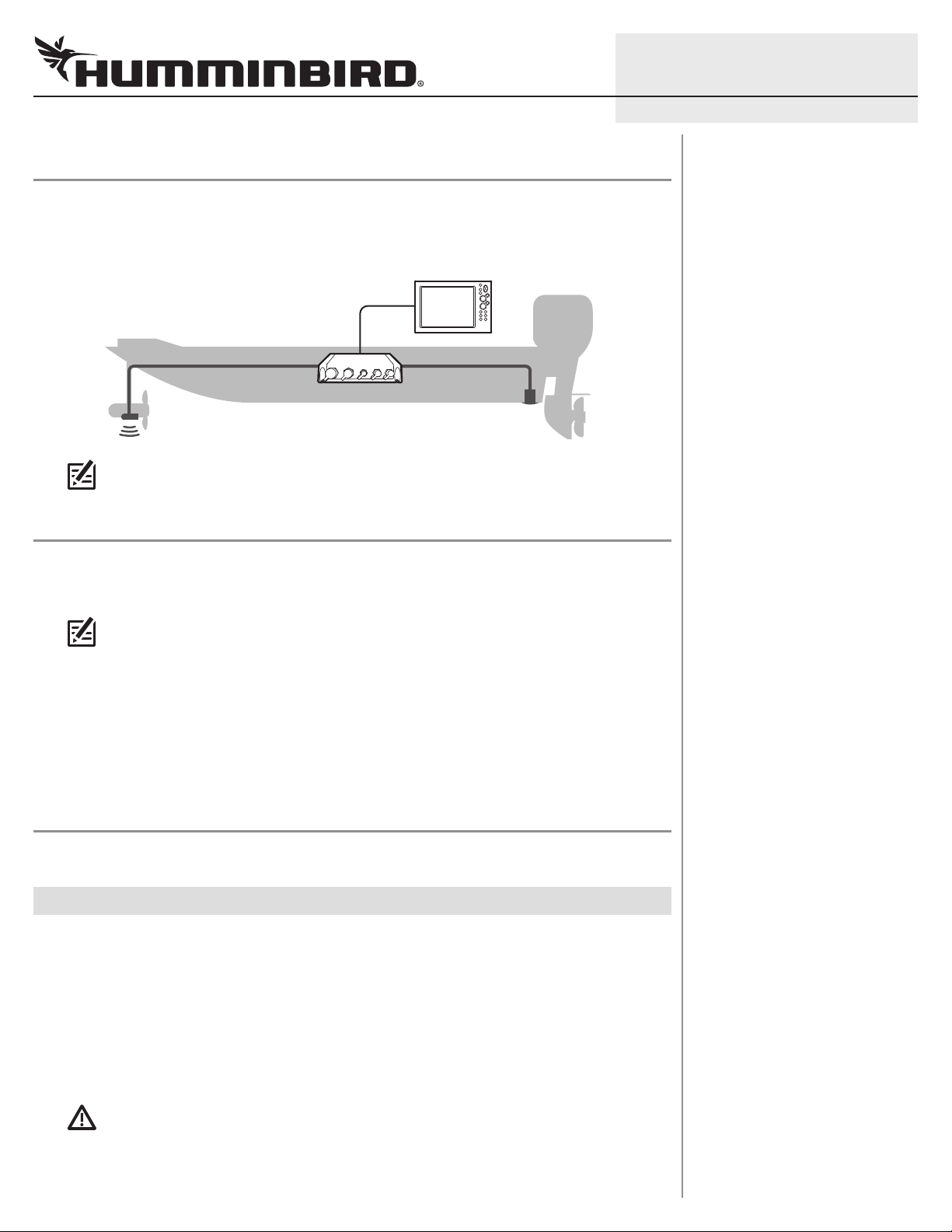
OVERVIEW
The Ethernet Black Box Sonar allows you to connect select transducers and accessories to your
SOLIX®, ONIX®, or ION® control head. Connect up to two Black Box Sonars on your Ethernet network.
Example of a Black Box Sonar Configuration
NOTE: To review and/or purchase compatible accessories for your control head
configuration, visit our Web site at humminbird.com or contact Customer Service.
PREPARATION
Following are instructions for the installation of this accessory. Before you start the installation, we
encourage you to read these instructions carefully in order to get the full benefit from your
Humminbird® accessory.
531812-1_B
NOTE: The illustrations in this manual may not look the same as your product, but your
unit will function in the same way.
Customer Service: If you find that any items are missing from your installation kit, visit our Web site
at humminbird.com or call Customer Service at 1-800-633-1468.
Supplies: In addition to the hardware supplied with your installation kit, you will need a powered hand
a 1/8" drill bit,
drill,
Humminbird Ethernet cable (separate purchase required). You may also need an adapter cable
(separate purchase required) if you plan to connect a previously installed transducer.
a Phillips screwdriver, a level, a pencil, tape or heat-shrink insulation, and a
INSTALLATION
Perform the procedures in the following sections to install the Black Box Sonar on your boat.
|
Determine the Mounting Location
1
The Black Box Sonar is designed to mount on any flat, level surface of your boat. Prior to installation,
you must first determine where to mount the Black Box Sonar.
1. Use a level to locate a suitable, flat area to mount the Black Box Sonar.
2. Place the Black Box Sonar in the chosen mounting location and test the length of the cables
(transducer, temp/speed, and power) to confirm that each cable will reach the Black Box Sonar.
3. Test the length of the Ethernet cable (separate purchase required) from the Black Box Sonar
to confirm it will reach the control head.
CAUTION! Do NOT mount the cables where the connectors could be submerged in water or
flooded. If cables are installed in a splash-prone area, it may be helpful to apply dielectric
grease to the inside of the connectors to prevent corrosion. Dielectric grease can be
purchased separately from a general hardware or automotive store.
Page 2
2
GROUNDGROUND
POSITIVEPOSITIVE
ETHERNET BLACK BOX SONAR Installation Guide
|
Install the Black Box Sonar
2
Once you have determined the mounting location, perform the following procedures to install the
Black Box Sonar on your boat.
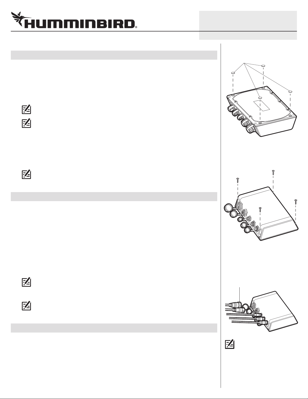
. Set the Black Box Sonar in place on the mounting surface. Mark the four mounting screw
1
locations with a pencil.
2. Set the Black Box Sonar aside, and drill the four mounting holes using a 1/8" drill bit.
NOTE: On fiberglass hulls, it is best to use progressively larger drill bits to reduce the
chance of chipping or flaking the outer coating.
NOTE: If the mounting surface is thin or made of a lightweight material, you may need to add
reinforcing material below the mounting surface in order to support the Black Box Sonar.
3. Insert the rubber feet (included), with the adhesive side facing down, into the four circular
recesses on the bottom of the Black Box Sonar. See the illustration Inserting the Rubber Feet.
4. Place the Black Box Sonar on the mounting surface and align the screw holes with the drilled
mounting holes. Insert the four #10 screws (included) through the screw holes and into the
drilled mounting holes, and hand-tighten using a Phillips screwdriver. Hand-tighten only!
NOTE: Apply marine-grade silicone caulk or sealant (separate purchase required) to both
screws and drilled holes as needed to protect your boat from water damage.
531812-1_B
Inserting the Rubber Feet
rubber feet
Installing the Black Box Sona r
|
Connect the Ethernet Cable
3
The Ethernet cable can be connected directly to the control head or to an additional Black Box Sonar
or Ethernet Switch on your network. Refer to your Ethernet Networking manual and the control head
installation guide for more information.
1. Unscrew the Ethernet port cover on the Black Box Sonar. Connect the Ethernet cable connector
to the port. Hand-tighten the screw nut to secure the cable connection.
2. Control Head: Connect the Ethernet cable connector to the Ethernet port on the back of the
control head.
Black Box Sonar: Connect the Ethernet cable connector to the Ethernet port.
Ethernet Switch: Connect the Ethernet cable connector to an Ethernet port.
NOTE: See the Ethernet Switch installation guide for more details.
3. Hand-tighten the screw nut to secure the cable connection.
NOTE: Make sure the port covers are tightly fastened over any unused connector ports.
Connectors that are left exposed may corrode.
|
Connect the Airmar® Temp/Speed Cable
4
If you have the Airmar Speed and Temperature Paddlewheel Accessory, see the instructions below to
connect the cable to the Black Box Sonar. Also, see the installation guide included with the accessory.
1. Unscrew the Speed/Temp port cover on the Black Box Sonar.
2. Connect the Speed/Temp cable connector to the Speed/Temp port. Hand-tighten the screw nut
to secure the cable connection.
Connecting Cables
to the Black B ox Sonar
(SM 3000 displayed below)
screw nut
NOTE: The connector ports are
keyed to prevent reversed
installation, so be careful not
to force the connector into the
port.
Page 3

3
GROUNDGROUND
POSITIVEPOSITIVE
ETHERNET BLACK BOX SONAR Installation Guide
|
Connect Transducer Cables
5
NOTE: Some Airmar and previously installed Humminbird transducers may require an
adapter cable to connect to the Black Box Sonar. For more information, visit our Web site
at humminbird.com or Airmar’s Web site at airmartechnology.com.
1. See the table below to determine the port connection(s) for your transducer type(s) and Black
Box Sonar model.
Transducer Type
Airmar 2D Sonar
Humminbird 2D Sonar
Humminbird Side Imaging®
or Down Imaging®*
Airmar CHIRP**
*MEGA Imaging™ transducers can be connected to the Black Box Sonar, but MEGA Imaging frequencies
are not supported.
**The Airmar CHIRP transducer requires an adapter cable to connect to the Black Box Sonar. See the
instructions in the next section to connect the adapter cable and CHIRP transducer cable to the Black
Box Sonar.
SM 1000
Port Connection
2D Sonar 2D Sonar Broadband
— SI/DI/2D Sonar SI/DI/2D Sonar
— SI/DI/2D Sonar SI/DI/2D Sonar
— — Broadband
SM 2000
Port Connection
SM 3000
Port Connection
531812-1_B
2. Unscrew the port cover on the Black Box Sonar.
3. Connect the transducer cable connector to the port.
4. Hand-tighten the screw nut to secure the cable connection.
|
Connect the CHIRP Transducer Adapter Cable (SM 3000 only)
6
If you plan to connect an Airmar CHIRP transducer, use the following instructions to connect it to the
CHIRP adapter cable (included with the SM 3000). Also, see the installation guide included with the
Airmar CHIRP transducer.
WARNING! Turn off power for all related equipment before you start the installation.
1. Turn off the power for the Humminbird control head and each connected accessory.
2. See the installation guide included with the Airmar CHIRP transducer to confirm the wiring and
that the bare wire colors match those shown in the following table.
WARNING! Your CHIRP transducer may have different wiring. It is important to refer to the
guide included with your transducer to confirm the wiring and cable connections.
3. Connect the adapter cable wires to the CHIRP transducer cable wires as shown in the following
table. Tape or apply heat-shrink insulation to each connection to prevent shorting the wiring.
NOTE: To protect the wire connections, use a junction or break-out box (separate purchase
required).
Page 4

4
ETHERNET BLACK BOX SONAR Installation Guide
CHIRP Adapter Cable Wires Airmar CHIRP Transducer Cable Wires Functionality
Orange
Orange & White
Brown
Brown & White
Green Orange XID
Green & White White Temperature
Drain (unshielded wires) Drain & Brown Ground/Drain
NOTE: Items labeled as High Frequency Pair refer to the higher of two given frequencies.
Items labeled as Low Frequency Pair refer to the lower of two given frequencies. For
example, a Low & Medium Frequency CHIRP transducer would use the medium frequencies
as the High Frequency Pair and the low frequencies as the Low Frequency Pair.
4. Unscrew the Broadband port cover on the Black Box Sonar.
5. Connect the adapter cable connector to the port. Hand-tighten the screw nut to secure the
cable connection.
Blue
High Frequency Pair
Black
Blue & White
Low Frequency Pair
Black & White
531812-1_B
|
Connect the Power Cable
7
The Black Box Sonar power cable (included) can be connected to the electrical system of the boat at
two locations: a fuse panel (usually located near the console) or directly to the battery.
CAUTION! Make sure that the power cable is disconnected from the Black Box Sonar at the
beginning of this procedure.
NOTE: Humminbird is not responsible for over-voltage or over-current failures. The Black
Box Sonar must have adequate protection through the proper selection and installation of
a 5 amp fuse (separate purchase required).
1. Refer to the table, Determine Your Voltage Requirement, to confirm the voltage requirement
for your Fishing System.
2a. If a fuse terminal is available, use crimp-on type electrical connectors (not included) that match
the terminal on the fuse panel. Depending on your control head model, attach the black wire to
ground (-) and the red wire to positive (+) 12 VDC or 24 VDC power (see Determine Your Voltage
Requirement). Install a 5 amp fuse (not included) for the protection of the accessory.
Humminbird is not responsible for over-voltage or over-current failures.
or...
2b. If you need to wire the power cable directly to a battery, obtain and install an inline fuse holder
and a 5 amp fuse (not included) for the protection of the accessory. Attach the black wire to
ground (-) and the red wire to positive (+). Humminbird is not responsible for over-voltage or
over-current failures.
Determine Your Voltage Requirement
Mo del Vo ltage
SOLIX
ONIX
ION
Connecting the Power Cable
GROUNDGROUND
12 VDC
12 VDC
12 VDC or 24 VDC
POSITIVEPOSITIVE
3. Connect the power cable connector to the port labeled POWER on the Black Box Sonar. The ports
are keyed to prevent reversed installation, so be careful not to force the connector into the
connector port. Hand-tighten the screw nut to secure the cable connection.
4. Install cable ties (separate purchase required) to prevent the cables from moving and pulling,
which could stress and potentially damage the cable connectors.
Proceed to the Set up Transducers and Select Sonar Sources section to set up your transducer source
on the control head.
Page 5

5
ETHERNET BLACK BOX SONAR Installation Guide
SET UP TRANSDUCERS AND SELECT SONAR SOURCES (OPTIONAL)
Transducers with ID or XID (Airmar transducers) are configured automatically in the system, and the
control head will automatically select the best sonar source based on transducer capabilities. Sonar
source information is available in your control head operations manual.
OTE: To set up a transducer manually (Initial Setup), change sonar sources, or troubleshoot
N
sonar sources, download the Transducer Setup Guide from our Web site at humminbird.com.
Open the Sonar Source Menu
Use the following instructions to open the Sonar Source Menu, where you can select sonar sources,
set the max depth and depth offset, and select other sonar settings for your connected transducers.
1. Press the HOME key.
2. Select Settings.
3. Select Sonar to access Noise Filter and individual Beam Select.
4. Select Sonar Source to set up transducers and choose sonar sources.
SET AIRMAR CHIRP SETTINGS (OPTIONAL)
Use the following instructions to set up transmit mode, sweep, frequency range, and other operation
preferences. The menus in this section are determined by the type of CHIRP transducer installed.
531812-1_B
1. Press the HOME key.
2. Select Settings.
3. Select Sonar.
4. Scroll to the CHIRP SONAR section to adjust the following menu settings:
Select Spectrum Sweep to transmit the transducer beams in a
sweeping range. To set the sweep range see Low/Medium/High
Frequency Spectrum.
Transmit Mode
Select Single Frequency to transmit the transducer beams at a
frequency set to your preference. To change the frequency, see
Low/Medium/High Frequency.
Beam Select
Low/Medium/High
Frequency
Low/Medium/High
Frequency Spectrum
If the selected sonar source includes more than one beam, you can
select which beams will be displayed in the sonar view.
The control head will automatically select a frequency for each
transducer beam. Use the Frequency Menus to adjust each frequency
higher or lower. Transmit Mode must be set to Single Frequency to
access these menus.
For each sweep range, set the start frequency and the end frequency.
Transmit Mode must be set to Spectrum Sweep to access these
menus.
Noise Filter
Use Noise Filter to limit interference on the sonar view from sources
such as your boat engine, turbulence, or other sonar devices.
Page 6

6
ETHERNET BLACK BOX SONAR Installation Guide
CONTACT HUMMINBIRD
eb site humminbird.com
W
E-mail service@humminbird.com
Telephone 1-800-633-1468
Direct Shipping Humminbird
Service Department
678 Humminbird Lane
Eufaula, AL 36027 USA
WARNING! This device should not be used as a navigational aid
to prevent collision, grounding, boat damage, or personal injury.
When the boat is moving, water depth may change too quickly
to allow time for you to react. Always operate the boat at very
slow speeds if you suspect shallow water or submerged objects.
WARNING! Disassembly and repair of this electronic unit should
only be performed by authorized service personnel. Any
modification of the serial number or attempt to repair the
original equipment or accessories by unauthorized individuals
will void the warranty.
531812-1_B
Environmental Compliance Statement: It is the intention of Johnson
Outdoors Marine Electronics, Inc. to be a responsible corporate citizen,
perating in compliance with known and applicable environmental
o
regulations, and a good neighbor in the communities where we make
or sell our products.
WEEE Directive : EU Directive 2002/96/EC “Waste of Electrical and
Electronic Equipment Directive (WEEE)” impacts most distributors,
sellers, and manufacturers of consumer electronics in the European
Union. The WEEE Directive requires the producer of consumer
electronics to take responsibility for the management of waste from
their products to achieve environmentally responsible disposal during
the product life cycle.
WEEE compliance may not be required in your location for electrical &
electronic equipment (EEE), nor may it be required for EEE designed
and intended as fixed or temporary installation in transportation
vehicles such as automobiles, aircraft, and boats. In some European
Union member states, these vehicles are considered outside of the
scope of the Directive, and EEE for those applications can be
considered excluded from the WEEE Directive requirement.
This symbol (WEEE wheelie bin) on product indicates the
product must not be disposed of with other household refuse. It
must be disposed of and collected for recycling and recovery of
waste EEE. Johnson Outdoors Marine Electronics, Inc. will mark
all EEE products in accordance with the WEEE Directive. It is our goal to
comply in the collection, treatment, recovery, and environmentally
sound disposal of those products; however, these requirements do vary
within European Union member states. For more information about
where you should dispose of your waste equipment for recycling and
recovery and/or your European Union member state requirements,
please contact your dealer or distributor from which your product was
purchased.
Airmar is a registered trademark of Airmar Technology Corp.
Down Imaging, Humminbird, ION, MEGA Imaging, ONIX, Side Imaging, and
SOLIX are trademarked by or registered trademarks of Johnson Outdoors
Marine Electronics, Inc.
© 2018 Johnson Outdoors Marine Electronics, Inc. All rights reserved.
 Loading...