

Humminbird SM 2000, SM 1000, SM 3000 Installation Manual
1
ETHERNET BLACK BOX SONAR Installation Guide
OVERVIEW
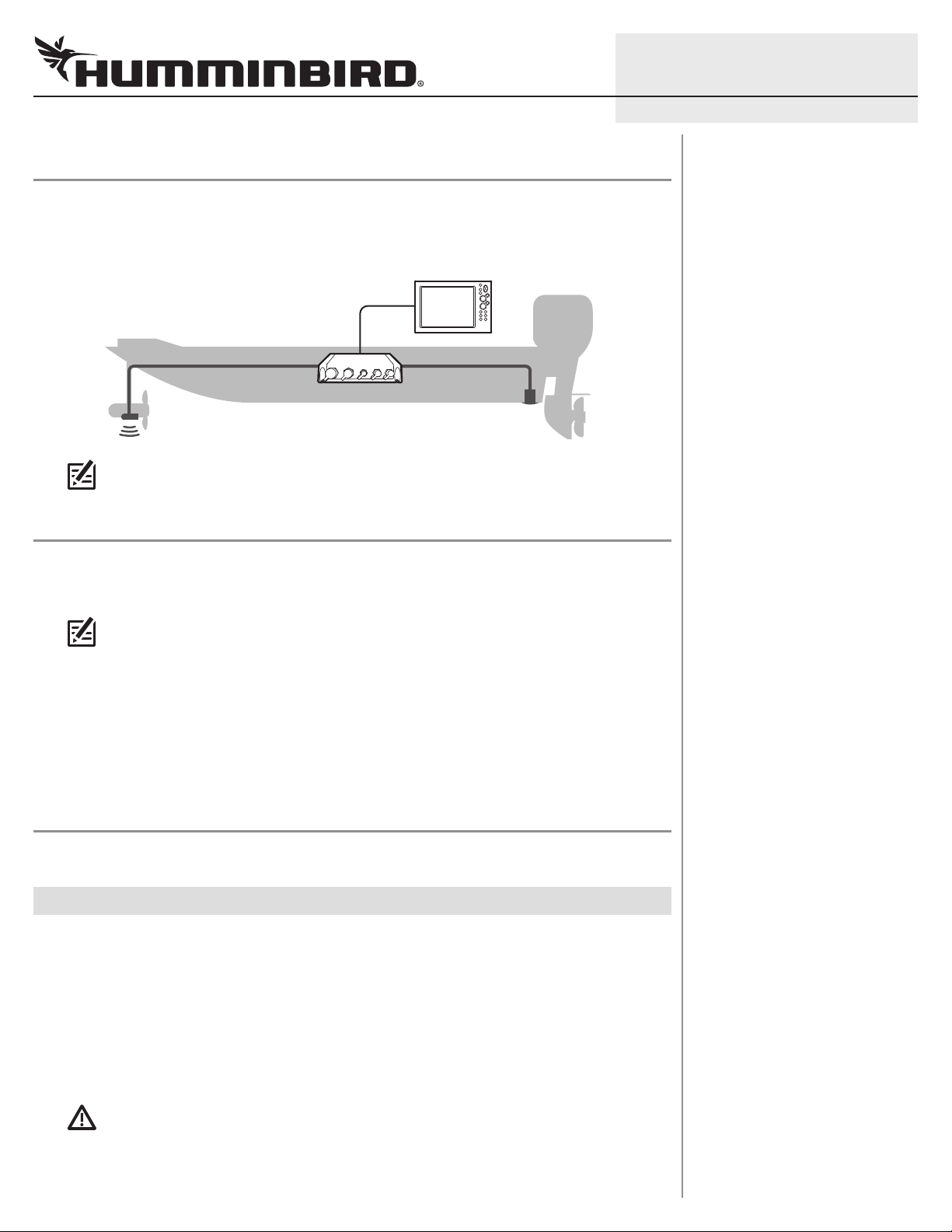
The Ethernet Black Box Sonar allows you to connect select transducers and accessories to your
SOLIX®, ONIX®, or ION® control head. Connect up to two Black Box Sonars on your Ethernet network.
Example of a Black Box Sonar Configuration
NOTE: To review and/or purchase compatible accessories for your control head
configuration, visit our Web site at humminbird.com or contact Customer Service.
PREPARATION
Following are instructions for the installation of this accessory. Before you start the installation, we
encourage you to read these instructions carefully in order to get the full benefit from your
Humminbird® accessory.
531812-1_B
NOTE: The illustrations in this manual may not look the same as your product, but your
unit will function in the same way.
Customer Service: If you find that any items are missing from your installation kit, visit our Web site
at humminbird.com or call Customer Service at 1-800-633-1468.
Supplies: In addition to the hardware supplied with your installation kit, you will need a powered hand
a 1/8" drill bit,
drill,
Humminbird Ethernet cable (separate purchase required). You may also need an adapter cable
(separate purchase required) if you plan to connect a previously installed transducer.
a Phillips screwdriver, a level, a pencil, tape or heat-shrink insulation, and a
INSTALLATION
Perform the procedures in the following sections to install the Black Box Sonar on your boat.
|
Determine the Mounting Location
1
The Black Box Sonar is designed to mount on any flat, level surface of your boat. Prior to installation,
you must first determine where to mount the Black Box Sonar.
1. Use a level to locate a suitable, flat area to mount the Black Box Sonar.
2. Place the Black Box Sonar in the chosen mounting location and test the length of the cables
(transducer, temp/speed, and power) to confirm that each cable will reach the Black Box Sonar.
3. Test the length of the Ethernet cable (separate purchase required) from the Black Box Sonar
to confirm it will reach the control head.
CAUTION! Do NOT mount the cables where the connectors could be submerged in water or
flooded. If cables are installed in a splash-prone area, it may be helpful to apply dielectric
grease to the inside of the connectors to prevent corrosion. Dielectric grease can be
purchased separately from a general hardware or automotive store.
2
GROUNDGROUND
POSITIVEPOSITIVE
ETHERNET BLACK BOX SONAR Installation Guide
|
Install the Black Box Sonar
2
Once you have determined the mounting location, perform the following procedures to install the
Black Box Sonar on your boat.
. Set the Black Box Sonar in place on the mounting surface. Mark the four mounting screw
1
locations with a pencil.
2. Set the Black Box Sonar aside, and drill the four mounting holes using a 1/8" drill bit.
NOTE: On fiberglass hulls, it is best to use progressively larger drill bits to reduce the
chance of chipping or flaking the outer coating.
NOTE: If the mounting surface is thin or made of a lightweight material, you may need to add
reinforcing material below the mounting surface in order to support the Black Box Sonar.
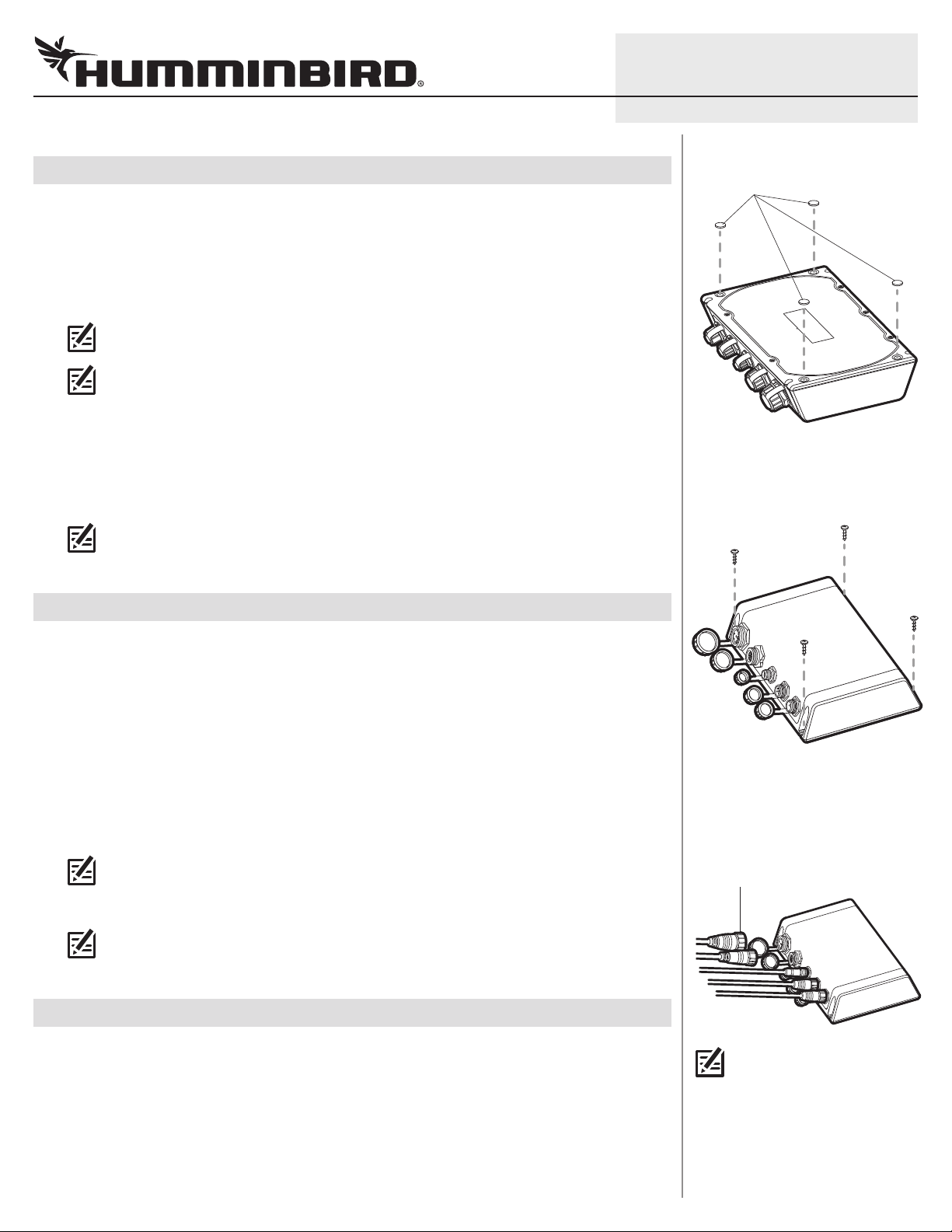
3. Insert the rubber feet (included), with the adhesive side facing down, into the four circular
recesses on the bottom of the Black Box Sonar. See the illustration Inserting the Rubber Feet.
4. Place the Black Box Sonar on the mounting surface and align the screw holes with the drilled
mounting holes. Insert the four #10 screws (included) through the screw holes and into the
drilled mounting holes, and hand-tighten using a Phillips screwdriver. Hand-tighten only!
NOTE: Apply marine-grade silicone caulk or sealant (separate purchase required) to both
screws and drilled holes as needed to protect your boat from water damage.
531812-1_B
Inserting the Rubber Feet
rubber feet
Installing the Black Box Sona r
|
Connect the Ethernet Cable
3
The Ethernet cable can be connected directly to the control head or to an additional Black Box Sonar
or Ethernet Switch on your network. Refer to your Ethernet Networking manual and the control head
installation guide for more information.
1. Unscrew the Ethernet port cover on the Black Box Sonar. Connect the Ethernet cable connector
to the port. Hand-tighten the screw nut to secure the cable connection.
2. Control Head: Connect the Ethernet cable connector to the Ethernet port on the back of the
control head.
Black Box Sonar: Connect the Ethernet cable connector to the Ethernet port.
Ethernet Switch: Connect the Ethernet cable connector to an Ethernet port.
NOTE: See the Ethernet Switch installation guide for more details.
3. Hand-tighten the screw nut to secure the cable connection.
NOTE: Make sure the port covers are tightly fastened over any unused connector ports.
Connectors that are left exposed may corrode.
|
Connect the Airmar® Temp/Speed Cable
4
If you have the Airmar Speed and Temperature Paddlewheel Accessory, see the instructions below to
connect the cable to the Black Box Sonar. Also, see the installation guide included with the accessory.
1. Unscrew the Speed/Temp port cover on the Black Box Sonar.
2. Connect the Speed/Temp cable connector to the Speed/Temp port. Hand-tighten the screw nut
to secure the cable connection.
Connecting Cables
to the Black B ox Sonar
(SM 3000 displayed below)
screw nut
NOTE: The connector ports are
keyed to prevent reversed
installation, so be careful not
to force the connector into the
port.
 Loading...