

Page 1
1
Side Imaging® Transducer
Thank You
Thank you for choosing Humminbird®, the #1 name in marine electronics. Humminbird has built its
reputation by designing and manufacturing top-quality, thoroughly reliable marine equipment. Genuine
Humminbird accessories offer the opportunity to upgrade and expand the capabilities of your Humminbird
product.
NOTE: Your transducer may not look exactly like the transducer shown in the illustrations, but it will mount in
exactly the same way.
Your Humminbird is designed for trouble-free use in even the harshest marine environment. In the unlikely
event that your Humminbird does require repairs, we offer an exclusive Service Policy - free of charge during
the first year after purchase, and available at a reasonable rate after the one-year period. For complete
details, see the Warranty section included in this manual.
Contact our Customer Service at 1-800-633-1468 or visit our Web site at humminbird.com.
Installation Overview
Following are instructions for the installation of this accessory. Before you start the installation, we
encourage you to read these instructions carefully in order to get the full benefit from your Humminbird
accessory.
Customer Service: If you find that any items are missing from your installation kit, visit our Web site at
humminbird.com or call our Customer Service at 1-800-633-1468.
531390-1_H
Transom Mounted Transducer
Areas of Possible Turbulence
Supplies: In addition to the hardware supplied with your transducer, you will need a powered hand drill and
various drill bits, various hand tools, including a ruler or measuring tape, level, pen or pencil, safety glasses
and dust mask, and marine-grade silicone sealant.
Installation
There are a number of ways to install a transducer on your boat. The transom mount installation provides
the least loss of signal since the transducer is mounted outside the boat hull. This installation also allows
adjustment of both running angle and depth after the transducer is mounted, which enables you to tune the
installation for best results. Also, the mounting hardware is designed to pivot the transducer body out of the
way should the boat strike debris in the water, or when trailering.
1.Locating the Transducer Mounting Position
Turbulence: You must first determine the best location on the transom to install the transducer. It is very
important to locate the transducer in an area which is relatively free of turbulent water. Consider the
following to find the best location with the least amount of turbulence:
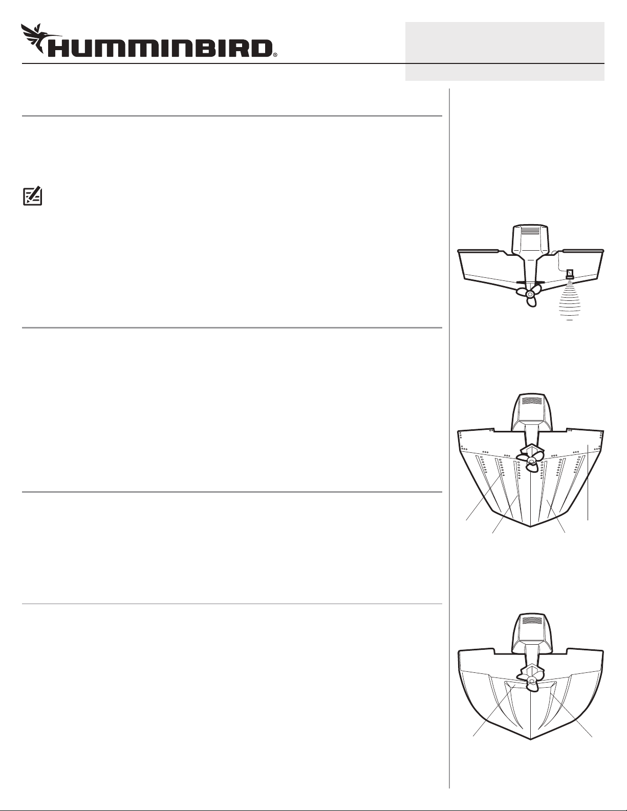
• As the boat moves through the water, turbulence is generated by the weight of the boat and the thrust
of the propeller(s) - either clockwise or counter-clockwise. This turbulent water is normally confined to
areas immediately aft of ribs, strakes or rows of rivets on the bottom of the boat, and in the immed iate
area of the propeller(s). Clockwise propellers create more turbulence on the port side. On outboard or
inboard/outboard boats, it is best to locate the transducer at least 15" to the side of the propeller(s).
rivets transom
strakes hull
Stepped Hull
• The best way to locate turbulence-free water is to view the transom while the boat is moving. This
method is recommended if maximum high-speed operation is a high priority. If this is not possible,
select a location on the transom where the hull forward of this location is smooth, flat and free of
protrusions or ribs.
step
rib
Page 2
2
L
evel
Side Imaging® Transducer
• On boats with stepped hulls, it may be possible to mount the trans ducer on the step. Do not mount the
transducer on the transom behind a step to avoid popping the transducer out of the water at higher
speeds. The transducer must remain in the water for the control head to maintain the sonar signal.
• If the transom is behind the propeller(s), it may be impossible to find an area clear from turbulence, and a
different mounting technique or transducer type should be considered. See the FAQ (Frequently Asked
Questions) section of our Web site at humminbird.com or call Customer Service at 1-800-633-1468.
• If you plan to trailer your boat, do not mount the transducer too close to trailer bunks or rollers to avoid
moving or damaging the transducer during loading and unloading of the boat.
Find a turbulence-free location at least 15" from the propeller(s) and not in line with trailer bunks or rollers.
531390-1_H
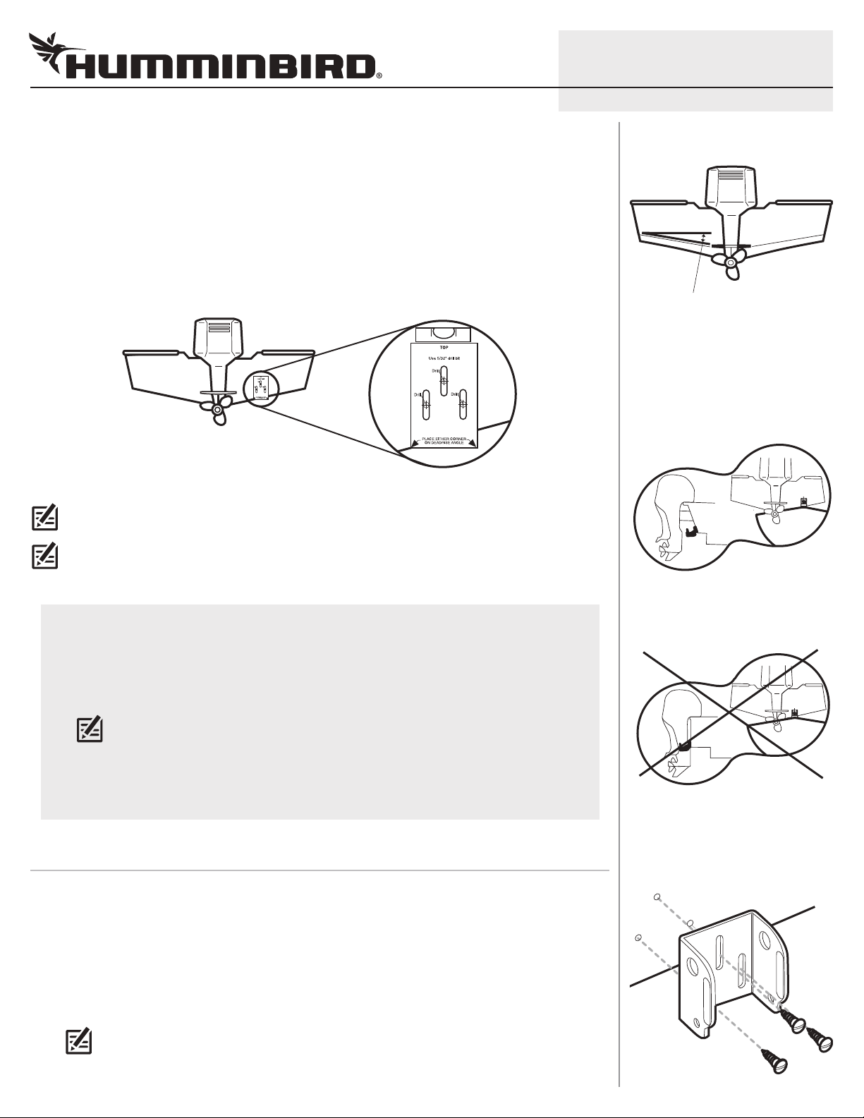
Deadrise
deadrise angle
Transducer Mount Position
Unobstructed View: The jack plate gives the transducer
safe distance from the motor and turbulence. The Side
Imaging has a clear view side-to-side.
NOTE: The hydrodynamic shape of your transducer allows it to point straight down without deadrise adjustment.
NOTE: If you cannot find a transom mount location that will work for your high-speed application, a different
mounting technique or transducer type should be considered. See the FAQ (Frequently Asked Questions) section of
our Web site at humminbird.com or call Customer Service at 1-800-633-1468.
Side Imaging: The Side Imaging transducer has some special requirements because of its side viewing
capabilities:
• The Side Imaging transducer must NOT have anything obstructing the ‘view’ of the side looking
beams; for example, nothing can be in the line of sight of these beams (not a hull, motor, or other
transducer, etc.)
NOTE: You may need to tilt the motor up and out of the way when using the side looking beams.
• In order for the side beams to be displayed accurately, the transducer must be mounted parallel
with the waterline. This positioning allows the beam elements to point straight down without
deadrise adjustment (see the illustration Deadrise).
2.Mounting the Bracket
In this procedure you will mount the bracket, using the mounting template provided as a guide. This
template allows you to mark where the mounting holes should be drilled.
Obstructed View: The transducer is too close to motor
turbulence, and the Side Imaging view is blocked by the
motor. The view cannot extend from side-to-side.
Attaching the Bracket
1. Cut out the transducer mounting template from this sheet. Match the mounting bracket screw slots to
the template screw slots.
2. Hold the template on the transom of the boat in the location you have selected. Align the template
vertically, matching the lower edge of the transom with the bottom corner of the template.
NOTE: If your propeller moves clockwise as the boat moves forward (as you're facing the stern of the boat
from behind), mount the transducer on the starboard side, and use the bottom left corner of the template. If
your propeller moves counter-clockwise as the boat moves forward (as you're facing the stern of the boat from
behind), mount the transducer on the port side, and use the bottom right corner of the template.
Page 3
3
Side Imaging® Transducer
3. Continue to hold the template on the transom of the boat, and use a pencil or punch to mark where to
drill the three mounting holes shown on the template.
4. Using a 5/32" bit, drill the three holes only to a depth of approximately 1".
NOTE: On fiberglass hulls, it is best to use progressively larger drill bits to reduce the chance of chipping or
flaking the outer coating.
5. Use a marine-grade silicone sealant to fill the drilled holes, especially if the holes penetrated the
transom wall.
6. Align the metal mounting bracket with the mounting holes. The center slot of your mounting bracket
should be above the two outer slots. This bracket and all other hardware supplied is top quality stainless
steel for maximum strength and corrosion protection. Insert the three 1" flat head wood screws into the
drilled holes, but do not completely tighten.
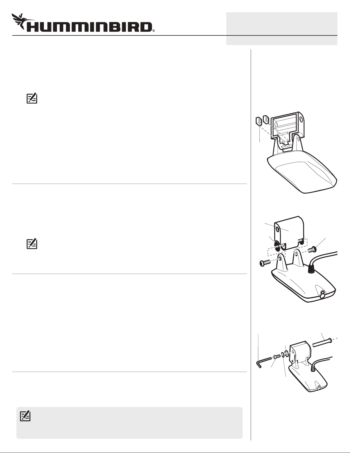
3.Assembling the Transducer
In this procedure you will attach the pivot to the transducer using the hardware provided.
1. Attach the pivot to the transducer body as shown in the illustration using the square nuts, toothed
washers, and two 1/4–20 x 5/8" machine screws. The square nuts will be prevented from rotating by the
pocket in the back of the pivot. The toothed washers must fit on the inside of the transducer ears,
between the pivot and the ears.
NOTE: An Allen wrench is provided which fits all of the 1/4–20 screws, but do not fully tighten the screws at
this time.
Inserting the Square Nuts
square
nuts
Attaching the Pivot
pivot
toothed
washer
531390-1_H
machine
screw
4.Attaching the Transducer to the Bracket
1. Slide the assembled transducer into the metal bracket from the bottom, aligning the large hole at the
top of the bracket with the hole in the pivot.
2. Insert the headed pin through the pivot holes in the bracket and pivot. The headed pin can be inserted
from either side of the bracket.
3. Place the nylon washer over the opposite end of the headed pin. Place the stainless washer over the
1/4–20 x 5/8" screw threads, then insert into the opposite end of the headed pin and finger tighten only.
The screw has a thread locking compound on the threads to prevent loosening, and should NOT be fully
tightened until all adjustments are made.
5.Running Position Adjustment
The running position of the transducer is now completely adjustable. Subsequent adjustment may be
necessary to tweak the installation after high speed testing. The mounting bracket allows height and tilt
adjustment; the pivot screws allow angle adjustment.
NOTE: Side Imaging is best performed at boat speeds from 2 to 6 mph. If the boat is stationary, the same
information is displayed over and over. If the boat is moving too quickly, there will be gaps between the strips
of information. The best boat speed to use will depend on the side range selected. Slower speeds are good for
longer ranges, while faster speeds can be used at shorter ranges.
Attaching the Transducer to the Bracket
allen wrench
nylon washer
(fits over headed pin)
screw
stainless washer
(fits over screw threads)
headed pin
Page 4

4
Side Imaging® Transducer
1. Adjust the angle of the transducer body first, so it is parallel with the hull of the boat, and fully tighten
the two pivot screws using the supplied Allen wrench. Access to the pivot screws is provided by the
lower holes in the side of the mounting bracket.
2. Next, adjust the height of the assembly so the face of the transducer is 1/8" to 1/4" beneath the bottom
of the transom, and fully tighten the three mounting screws. In order to gain access to the mounting
screws, the transducer assembly must be pivoted up into the bracket as shown.
CAUTION! Be careful not to alter the running angle, as some force is necessary to pivot the assembly.
3. If access to the top mounting hole is not possible due to the selected height of the transducer, fully
tighten the two lower screws. Remove the headed pivot pin and the transducer assembly, tighten the
top screw, and then reassemble.
4. Confirm that the pivot angle has not changed and that all mounting screws are fully tightened.
6.Routing the Cable
The transducer cable has a low profile connector which must be routed to the point where the control head
is mounted. There are several ways to route the transducer cable to the area where the control head is
installed. The most common procedure routes the cable through the transom into the boat.
531390-1_H
Tightening the Pivot Screw
allen wrench
Tightening the Mounting Screws
NOTE: Your boat may have a pre-existing wiring channel or conduit that you can use for the transducer cable.
1. Unplug the other end of the transducer cable from the control head. Make sure that the cable is long
enough to accommodate the planned route by running the cable over the transom.
CAUTION! Do not cut or shorten the transducer cable, and try not to damage the cable insulation. Route the
cable as far as possible from any VHF radio antenna cables or tachometer cables to reduce the possibility of
interference. If the cable is too short, extension cables are available to extend the transducer cable up to a total of
50'. For assistance, contact Customer Service at humminbird.com or call 1-800-633-1468 for more information.
CAUTION! Do NOT mount the cables where the connectors could be submerged in water or flooded. If cables
are installed in a splash-prone area, it may be helpful to apply dielectric grease to the inside of the connectors to
prevent corrosion. Dielectric grease can be purchased separately from a general hardware or automotive store.
NOTE: The transducer can pivot up to 90 degrees in the bracket. Allow enough slack in the cable for this
movement. It is best to route the cable to the side of the transducer so the transducer will not damage the
cable during movement.
2a. If you are routing the cable over the transom of the boat, secure the cable by attaching the cable clamp
to the transom, drilling 9/64" diameter holes for #8 x 5/8" wood screw(s), go directly to procedure 7,
Connecting the Cable.
or...
2b. If you will be routing the cable through a hole in the transom, drill a 5/8" diameter hole above the
waterline. Route the cable through this hole, then fill the hole with marine-grade silicone sealant and
proceed to the next step immediately.
Routing the Cable
escutcheon
plate
5/8" hole
cable
clamp
3. Place the escutcheon plate over the cable hole and use it as a guide to mark the two escutcheon plate
mounting holes. Remove the plate, drill two 9/64" diameter x 5/8" deep holes, and then fill both holes
with marine-grade silicone sealant. Place the escutcheon plate over the cable hole and attach with two
#8 x 5/8" wood screws. Hand tighten only!
4. Route and secure the cable by attaching the cable clamp to the transom. Drill one 9/64" diameter x 5/8"
deep hole, then fill the hole with marine-grade silicone sealant, then attach the cable clamp using a
#8 x 5/8" screw. Hand tighten only!
Page 5

5
Side Imaging® Transducer
NOTE: If there is excess cable that needs to be gathered at one location, dress the cable routed from both
directions so that a single loop is left extending from the storage location. Doubling the cable up from this
oint, form the cable into a coil. Storing excess cable using this method can reduce electronic interference.
p
7.Connecting the Cable
1. Insert the transducer cable into the appropriate terminal slot. The cable connectors are labeled, and
there are corresponding labels on the cable holder on the rear of the fishfinder. The slots are keyed to
prevent reversed installation, so be careful not to force the connector into the holder.
8.Test and Finish the Installation
Once you have installed both the control head and the transom transducer, and have routed all the cables,
you must perform a final test before locking the transducer in place. Testing should be performed with the
boat in the water.
1. Press POWER once to turn on the control head. If the unit does not power-up, make sure that the
connector holder is fully seated in the receptacle and that power is available.
2. If all connections are correct and power is available, the Humminbird control head will enter Normal
operation.
531390-1_H
Storing Excess Cable
3. If the bottom is visible on-screen with a digital depth readout, the unit is working properly. Make sure
that the boat is in water greater than 2' but less than the depth capability of the unit, and that the
transducer is fully submerged, since the sonar signal cannot pass through air.
NOTE: The transducer must be submerged in water for reliable transducer detection.
4. If the unit is working properly, gradually increase the boat speed to test high-speed performance. If the
unit functions well at low speeds, but begins to skip or miss the bottom at higher speeds, the transducer
requires adjustment.
5. If you have the correct angle set on the transducer, yet lose a bottom reading at high speed, adjust the
transducer to a lower depth in the water. If you reach the top of the screw slots and continue to lack
high speed performance, increase the angle of the transducer by lowering the back of the transducer in
increments of 1/8".
NOTE: It is often necessary to make several incremental transducer adjustments before optimum high speed
performance is achieved. Due to the wide variety of boat hulls, however, it is not always possible to obtain high
speed depth readings.
NOTE: The deeper the transducer is in the water, the more likely that a rooster tail of spray will be generated
at high speeds, so make sure that the transducer is as high as it can be and still be submerged in the water.
6. Once you have reached a consistently good sonar signal at the desired speeds, fully tighten your
assembly to lock it into place.
Page 6

6
Side Imaging® Transducer
Maintenance
If your boat remains in the water for long periods of time, algae and
other marine growth can reduce the effectiveness of the transducer.
Periodically clean the face of the transducer with a mild, marine-safe
and plastic-safe soap or solution.
NOTE: To clean the transducer, you may need to pivot the transducer up
in the bracket.
If your boat remains out of the water for a long period of time, it may
take some time to wet the transducer after it is returned to the water.
Small air bubbles can cling to the surface of the transducer and
interfere with proper operation. These bubbles will dissipate with time,
or you may wipe the face of the transducer with your fingers after the
transducer is in the water.
531390-1_H
1-Year Limited Warranty
We warrant the original retail purchaser that products made by Humminbird
have been manufactured free from defects in materials and workmanship.
his warranty is effective for one year from the date of original retail
T
purchase. Humminbird products found to be defective and covered by this
warranty will be repaired or replaced free of charge at Humminbird's option
an d ret urned t o th e cus tomer f reight prepaid. Hummi nbird's sole
responsibility under this warranty is limited to the repair or replacement of a
product that has been deemed defective by Humminbird. Humminbird is not
responsible for charges connected with the removal of such product or
reinstallation of replaced or repaired parts; or shipping charges to the
factory or authorized service center (if outside the U.S.).
This warranty does not apply to a product that has been:
• Improperly installed;
• Used in an installation other than that recom mended in the product
installation and operation instructions;
• Damaged or has failed because of an accident or abnormal operation;
• Repaired or modified by entities other than Humminbird.
Please retain your original receipt as a proof of the purchase date. This will
be required for in-warranty service.
THIS WARRANTY IS EXPRESSLY IN LIEU OF ANY OTHER WARRANTIES,
OBLIGATIONS OR LIABILITIES ON THE PART OF HUMMINBIRD AND WILL
BE THE CUSTOMER'S EXCLUSIVE REMEDY, EXCEPT FOR ANY APPLICABLE
IMPLIED WARRANTIES UNDER STATE LAW WHICH ARE HEREBY LIMITED
IN DURATION TO ONE YEAR FROM THE DATE OF ORIGINAL PURCHASE. IN
NO EVENT WILL HUMMINBIRD BE LIABLE FOR ANY INCIDENTAL OR
CONSEQUENTIAL DAMAGES FOR BREACH OF ANY EXPRESS OR IMPLIED
WARRANTY RELATING TO THE PRODUCTS.
Some states do not allow limitations on an implied warranty, or the
exclusion of incidental or consequential damages, so the above exclusions
may not apply to you. You may also have other rights, which vary from state
to state.
Page 7

7
Side Imaging® Transducer
Humminbird Service Policy
Even though you'll probably never need to take advantage of our incredible
service policy, it's good to know that we back our products this confidently.
e do it because you deserve the best. We will make every effort to repair
W
your unit within three business days from the receipt of your unit at our
factory. This does not include shipping time to and from our factory. Units
received on Friday are typically shipped by the following Wednesday, units
received Monday are typically shipped by Thursday, etc.
All repair work is performed by factory-trained technicians to meet exacting
factory specifications. Factory-serviced units go through the same rigorous
testing and quality control inspections as new production units.
After the original warranty period, a standard flat rate service charge will be
assessed for each repair (physical damage and missing parts are not
included). Any repairs made after the original warranty will be warranted
for an additional 90 days after service has been performed by our factory
technicians. You can contact Customer Service or visit our Web site to
verify the flat rate repair fee for your product (visit the Product Support
section):
http://www.humminbird.com
We reserve the right to deem any product unserviceable when replacement
parts are no longer available or impossible to obtain. This Service Policy is
valid in the United States only. This applies only to Humminbird products
returned to our factory in Eufaula, Alabama. This Service Policy is subject
to change without notice.
531390-1_H
Returning Your Unit for Service
Before sending your unit in for repair, please contact the factory, either by
phone or by email, to obtain a Repair Authorization Number for your unit.
NOTE: Please do not return your Humminbird to the store for service.
Please have your product model name and serial number available
before calling the factory. If you contact the factory by e-mail, please
include your product model name and serial number in the e-mail, and
use Request for Repair Authorization Number for your e-mail subject
header. You should include your Repair Authorization Number in all
subsequent communications about your unit.
For IN-WARRANTY service, complete the following steps
• Obtain a Repair Authorization Number from Humminbird Customer
Service.
• Tag product with your name, street address, phone number and
your assigned Repair Authorization Number.
• Include a brief written description of the problem.
• Include a copy of your receipt (to show proof and date of purchase).
• Return product freight prepaid to Humminbird, using an insured
carrier with delivery confirmation.
:
DOMESTIC (USA) CUSTOMERS:
PLEASE DO NOT RETURN THIS PRODUCT TO STORE FOR SERVICE
For all technical issues please call 1-800-633-1468
or visit humminbird.com, click SUPPORT.
Please reference product serial number and
model number when contacting Humminbird.
For OUT-OF-WARRANTY service, complete the following steps:
• Obtain a Repair Authorization Number from Humminbird Customer
Service.
• Include payment in the form of credit card number and expiration
date, or a money order. Please do not send cash.
• Tag product with your name, street address, phone number and
your assigned Repair Authorization Number.
• Include a brief written description of the problem.
• Return product freight prepaid to Humminbird, using an insured
carrier with delivery confirmation.
Page 8

8
Drill
Drill
Drill
Use 5/32”
drill bit.
TOP
PLACE EITHER CORNER
ON DEADRISE ANGLE
Remove and use for
Transducer Installation
Side Imaging® Transducer
Contact Humminbird
Web site humminbird.com
E-mail service@humminbird.com
Telephone 1-800-633-1468
Direct Shipping Humminbird
Service Department
678 Humminbird Lane
Eufaula, AL 36027 USA
WARN ING! This device should not be used as a navigational aid to
prevent collision, grounding, boat damage, or personal injury. When the
boat is moving, water depth may change too quickly to allow time for you to
react. Always operate the boat at very slow speeds if you suspect shallow
water or submerged objects.
WARNING! Disassembly and repair of this electronic unit should only be
performed by authorized service personnel. Any modification of the serial
number or attempt to repair the original equipment or accessories by
unauthorized individuals will void the warranty.
531390-1_H
Mounting Template
ENVIRONMENTAL COMPLIANCE STATEMENT: It is the intention
of Johnson Outdoors Marine Electronics, Inc. to be a responsible corporate citizen,
operating in compliance with known and applicable environmental regulations, and
a good neighbor in the communities where we make or sell our products.
WE E E DI R ECT I V E: EU Directive 2002/96/EC “Waste of Electrical and
Electronic Equipment Directive (WEEE)” impacts most distributors, sellers, and
manufacturers of consumer electronics in the European Union. The WEEE Directive
requires the producer of consumer electronics to take responsibility for the
management of waste from their products to achieve environmentally responsible
disposal during the product life cycle.
WEEE compliance may not be required in your location for electrical & electronic
equipment (EEE), nor may it be required for EEE designed and intended as fixed or
temporary installation in transportation vehicles such as automobiles, aircraft, and
boats. In some European Union member states, these vehicles are considered
outside of the scope of the Directive, and EEE for those applications can be
considered excluded from the WEEE Directive requirement.
This symbol (WEEE wheelie bin) on product indicates the product must not
be disposed of with other household refuse. It must be disposed of and
collected for recycling and recovery of waste EEE. Johnson Outdoors Marine
Electronics, Inc. will mark all EEE products in accordance with the WEEE
Directive. It is our goal to comply in the collection, treatment, recovery, and
environmentally sound disposal of those products; however, these requirements do
vary within European Union member states. For more information about where you
should dispose of your waste equipment for recycling and recovery and/or your
European Union member state requirements, please contact your dealer or
distributor from which your product was purchased.
© 2017 Johnson Outdoors Marine Electronics, Inc. All rights reserved.
 Loading...